


Instructions for Use
021774/07/14
Weather Station Compact WSC11
4.9056.10.00x
2 - 40 021774/07/14
Safety Instructions
Before operating with or at the device/product, read through the operating instructions.
This manual contains instructions which should be followed on mounting, start-up, and operation.
A non-observance might cause:
- failure of important functions
- endangerment of persons by electrical or mechanical effect
- damage to objects
Mounting, electrical connection and wiring of the device/product must be carried out only by a qualified
technician who is familiar with and observes the engineering regulations, provisions and standards applicable in
each case.
Repairs and maintenance may only be carried out by trained staff or Adolf Thies GmbH & Co. KG. Only
components and spare parts supplied and/or recommended by Adolf Thies GmbH & Co. KG should be used
for repairs.
Electrical devices/products must be mounted and wired only in a voltage-free state.
Adolf Thies GmbH & Co KG guarantees proper functioning of the device/products provided that no
modifications have been made to the mechanics, electronics or software, and that the following points are
observed:
All information, warnings and instructions for use included in these operating instructions must be taken into
account and observed as this is essential to ensure trouble-free operation and a safe condition of the measuring
system / device / product.
The device / product is designed for a specific application as described in these operating instructions.
The device / product should be operated with the accessories and consumables supplied and/or recommended
by Adolf Thies GmbH & Co KG .
Recommendation: As it is possible that each measuring system / device / product may, under certain conditions,
and in rare cases, may also output erroneous measuring values, it is recommended using redundant systems
with plausibility checks for security-relevant applications.
Environment
As a longstanding manufacturer of sensors Adolf Thies GmbH & Co KG is committed to the
objectives of environmental protection and is therefore willing to take back all supplied
products governed by the provisions of "ElektroG" (German Electrical and Electronic
Equipment Act) and to perform environmentally compatible disposal and recycling. We are
prepared to take back all Thies products concerned free of charge if returned to Thies by our
customers carriage-paid.
Make sure you retain packaging for storage or transport of products. Should packaging
however no longer be required, please arrange for recycling as the packaging materials are
designed to be recycled.
Documentation
© Copyright Adolf Thies GmbH & Co KG, Göttingen / Germany
Although these operating instruction has been drawn up with due care, Adolf Thies GmbH & Co KG can accept
no liability whatsoever for any technical and typographical errors or omissions in this document that might
remain.
We can accept no liability whatsoever for any losses arising from the information contained in this document.
Subject to modification in terms of content.
The device / product should not be passed on without the/these operating instructions.

3 - 40 021774/07/14
Contents
1 Device version ........................................................................................................................... 5
2 Application ................................................................................................................................. 5
3 Structure / Mode of operation .................................................................................................... 6
4 Installation of COMPACT WSC11 Weather Station ................................................................... 8
4.1 Selection of installation site ................................................................................................. 8
4.2 Mechanical installation ................................................................ ........................................ 9
4.2.1 Alignment to north....................................................................................................... 10
4.3 Electrical installation .......................................................................................................... 11
4.3.1 Cable, cable preparation, connector installation .......................................................... 11
4.3.2 Diagram of connections .............................................................................................. 12
4.3.3 Connection using cable 509 584 / 509 585 (optional accessory)................................. 12
5 Maintenance ............................................................................................................................ 13
6 Interface .................................................................................................................................. 14
6.1 Command interpreter THIES ................................................................ ............................. 14
6.1.1 Data telegrams ........................................................................................................... 15
6.2 Command interpreter MODBUS RTU ................................................................................ 19
6.2.1 Measuring values (Input Register) .............................................................................. 20
6.2.2 Commands (Holding Register) .................................................................................... 24
6.3 Commands and description ............................................................................................... 25
6.3.1 Command AI ............................................................................................................... 25
6.3.2 Command BR ............................................................................................................. 26
6.3.3 Command CI .............................................................................................................. 26
6.3.4 Command DC ............................................................................................................. 27
6.3.5 Command DO ................................................................................................ ............. 27
6.3.6 Command FB ............................................................................................................. 27
6.3.7 Command ID .............................................................................................................. 27
6.3.8 Command KY ............................................................................................................. 28
6.3.9 Command LC ............................................................................................................. 28
6.3.10 Command RS ................................................................................................ .......... 29
6.3.11 Command SH ................................................................................................ .......... 29
6.3.12 Command SV .......................................................................................................... 30
6.3.13 Command TR .......................................................................................................... 30
6.3.14 Command TT .......................................................................................................... 31
6.3.15 Command TZ .......................................................................................................... 31
7 LED signals ............................................................................................................................. 32
8 Technical data ......................................................................................................................... 33
9 Dimension drawing [in mm] ..................................................................................................... 36
10 Accessories (optional) .......................................................................................................... 37

4 - 40 021774/07/14
11 EC-Declaration of Conformity ............................................................................................... 38
Tables
Table 1 : Status word ..................................................................................................................... 16
Table 2 : Measured value telegram ................................................................................................ 18
Table 3 : Sensor data telegram ...................................................................................................... 19
Table 4 : MODBUS Frame ............................................................................................................. 19
Table 5: MODBUS Exceptions ....................................................................................................... 20
Table 6 : MODBUS Input Register .................................................................................................. 23
Table 7 : List of commands ............................................................................................................ 25
Figures
Figure 1 : LEDs .............................................................................................................................. 32
Figure 2 : Spectrum of brightness sensors ..................................................................................... 35
Figure 3 : Directional characteristics of brightness sensors ............................................................ 35
Figure 4 : Spectrum for global irradiance sensor ............................................................................ 36
Instructions for use
These instructions for use describe all application and adjustment options for the device.
These detailed instructions allow users to modify the factory settings to their needs via the serial
interface of the Weather Station Compact WSC11.
Scope of supply
1 Weather Station Compact WSC11.
1 Copy of the instructions for uses.
For assisting the parameter settings and/or special configurations there is our cost-free Device Utility
Tool art.-no. 9.1700.81.000 available for you for download.
Please send a short e-mail to info@thiesclima.com, keyword “Utility Tool WSC 11” in the subject
heading, as well as your sender information and our order number / invoice number.
We will then let you have your log-in for the download.

5 - 40 021774/07/14
1 Device version
Designation
Order No.
Output
terminal
Data format
Operating voltage
WEATHER STATION
COMPACT WSC11
4.9056.10.000
1 x RS485
Data in ASCII format
(command interpreter:
THIES)
18...30V DC
18...28V AC
WETTERSTATION
COMPACT WSC11
4.9056.10.001
1 x RS485
Data in binary format
(command interpreter:
MODBUS RTU)
18...30V DC
18...28V AC
2 Application
The WEATHER STATION COMPACT WSC11 is designed for use in building services automation
systems (e.g. shade protection control). The WSC11 features the following measured variables:
Wind speed.
Wind direction.
4 x brightness (north / east / south / west).
Twilight.
Global irradiance.
Precipitation.
Air temperature.
Absolute air pressure.
Relative air pressure.
Time / date.
Geostationary data (local altitude, longitude and latitude).
Position of the sun (elevation / azimuth).
Relative air humidity.
Absolute humidity.
Dew-point temperature.
Inside temperature of housing.
The interface to the device is digital and consists of an RS485 interface in half-duplex mode. Together
with ID-based communications the interface allows the Weather Station to be operated in a bus. Two
data protocols are available:
ASCII (THIES- format).
Binary (MODBUS RTU).

6 - 40 021774/07/14
3 Structure / Mode of operation
Wind speed / wind direction:
Wind measurement is based on the hot wire principle. The underside of the housing is equipped with a
heated cylindrical sensor. A PID controller adjusts the temperature of the cylinder to a temperature that
is constantly increased in relation to the environment. The supplied heat energy is a measure of wind
speed.
The metal cylinder contains four temperature-measuring resistors. These resistors are thermally
coupled with the cylinder and positioned according to the 4 points of the compass. When an incident
flow affects the cylinder as a function of the wind direction, this is accompanied by a temperature
gradient which is registered by the measuring resistors. The relationships between the 4 temperature
values are used to calculate the wind direction.
In case the wind direction cannot be determined because the wind velocity is 0m/s, the value is set to
0. Wind from the north is displayed with 360°.
Brightness:
The brightness measurement is carried out via 4 Silicium photo sensors, which are aligned to the 4
cardinal directions in the mean elevation angle (40°).
Twilight:
Twilight means the light diffusion in the atmosphere, which arises with the smooth transition between
day and night before the beginning or after the end of day.
i.e., the solar disc is not visible.
The twilight is direction-independent.
It is calculated from the sum of the 4 measuring values of the direction-independent brightness
sensors.
A change to the mean value from the 4 brightness values is possible by command.
Global irradiance:
A silicon PIN photodiode is used to measure global irradiance. The sensor is positioned horizontally
and registers the diurnal values of the solar irradiation intensity.
Precipitation:
The detection of precipitation is based on capacitance measurement, i.e. the capacity of the sensor
surface varies when wet. The sensor is installed in the housing cover. An integrated heating system
adjusts the sensor area to an overtemperature in relation to the ambient temperature. This
overtemperature (approx. 2K) prevents bedewing of the sensor surface. The thermal output is
increased with precipitation. This accelerates drying of the sensor, allowing the time at which
precipitation ended to be identified more accurately.

7 - 40 021774/07/14
Air temperature:
A PT1000 measuring resistor is used to measure the air temperature. The sensor is mounted on a
flexible printed board and positioned in the lower section of the housing.
Air pressure:
Absolute air pressure is measured with a piezoresistive MEMS sensor.
To make a meaningful comparison between air pressure values simultaneously measured at different
locations, they need to be converted to a common datum (height above sea level). The calculation is
referred to the height above sea level (QNH) according to the international altitude formula (DIN
ISO2533).
Ph = air pressure at local altitude
Pb = air pressure at height above sea level
= -0065K/m
gn = 9.80665m/s
2
R = 287.05287m2/K/s2
Tb = 288.15K
The station height, required for the calculation, can be entered manually by the Command SH, or can
be determined automatically by GPS.
If you want to achieve an accuracy of 0.1hPa, referred to sea level, the local altitude (altitude of the
baro transmitter) must be given up to an accuracy of 0.8m.
Time / date and geostationary data:
The Weather Station has a GPS receiver with a built-in RTC. This allows it to receive the position of
the Weather Station (degree of longitude/latitude, local altitude) time (UTC) and date. The GPS
receiver does not need alignment.
The built-in RTC (Real Time Clock) is buffered with a backup capacitor and retains its data without a
voltage supply for a period of minimum 3 days.
Position of the sun (elevation / azimuth):
On the basis of the GPS data the current sun position is calculated every second.
Humidity measurement:
A built-in hygro-thermosensor is used to measure humidity levels. The sensor has a small air exchange
volume thanks to its compact design and responds to changes in humidity in seconds.
A software module uses the relative humidity and air temperature to calculate absolute humidity and
the dew-point temperature.
R
g
T
b
n
b
hphp
)1()(

8 - 40 021774/07/14
Inside temperature of housing:
A silicon temperature sensor measures the temperature inside the housing.
GPS-Receiver:
The weather station has a GPS receiver with integrated RTC (Real Time Clock) for receiving the
position of the weather station, and time + date (UTC).
An alignment of the GPS receiver is not necessary.
The integrated RTC is buffered for a period of 3 days.
General information:
After activation of the WSC11 the first satellite data are available after approx. 2.5min.
When receiving the signals from one satellite: time with an accuracy of < 1µs.
When receiving the signals from three satellites: position with an accuracy of < 20m
When receiving the signals from four satellites: altitude, referred to the WGS84-
ellipsoid, with an accuracy < 30m
4 Installation of COMPACT WSC11 Weather Station
Please note:
The working position of the COMPACT WSC11 Weather Station is
horizontal (plug connection underneath).
During installation, de-installation, transport or maintenance of the
COMPACT WSC11 Weather Station make sure that no water gets
into the device and connector.
4.1 Selection of installation site
An exposed position should be selected for this site. Measurement properties should not be influenced
by light reflections, cast shadows or the device being positioned in the lee of the wind. Protection
against lightning and overvoltages should also be provided by the customer.

9 - 40 021774/07/14
4.2 Mechanical installation
The intended installation of the Weather Station WSC11 requires the use of a pipe socket / pipe
with an outside diameter of ≤25mm. The inside diameter must be ≥19mm to admit the
connector and cable.
Tool:
Hexagon socket wrench SW2mm
(socket wrench).
Procedure:
1. Push cable/plug connection
through the bore hole of the mast,
tube, bracket etc.
2. Put WSC11 on mast, tube.
3. Align WSC11 to “north”.
(Procedure see chapter 4.2.1).
4. Secure WSC11 by the M4hexagon socket screw.
Attention:
The hexagon
socket screw
is to be
tightened by
max. 0.6Nm.
When using the
mounting angel article no. 509276 (see
chapter accessories) the guide angles
must be removed, see fig.
The mounting angle is not included in
delivery.
Remark: Tube and mounting angle are not included in delivery.
10 - 40 021774/07/14
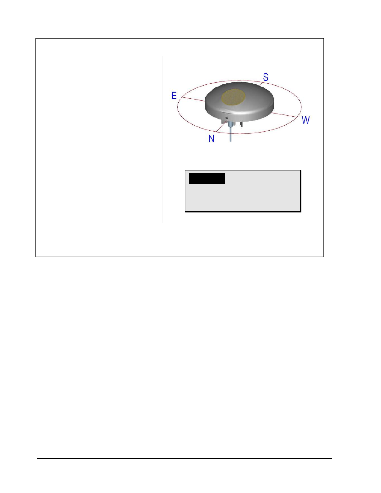
4.2.1 Alignment to north
For the exact determination of wind- and brightness direction the WEATHER STATION COMPACT
WSC11 must be mounted in north alignment (geographic north).
The hexagon socket screw serves as
north marking (N)
Tool:
Hexagon socket wrench SW2mm
(socket wrench).
Procedure:
1. Detect a prominent object in the
surrounding area (tree, building
etc.) in north direction by means of
a compass.
2. Via the north marking (N) and an
imaginary north-south axis the
weather station is to be located on
the prominent object.
3. Align weather station.
The north marking must indicate to
the geographic north.
4. In case of match the weather
station is to be secured by an M4hexagon socket screw.
Attention:
The hexagon socket
screw is to be tightened
by max. 0.6Nm.
Remark:
With the north alignment by means of a compass, the local variation (deviation in direction of a
compass needle from the true north direction) by interfering magnetic fields, and magnetic field
influences by hardware and electric cable are to be considered.
11 - 40 021774/07/14
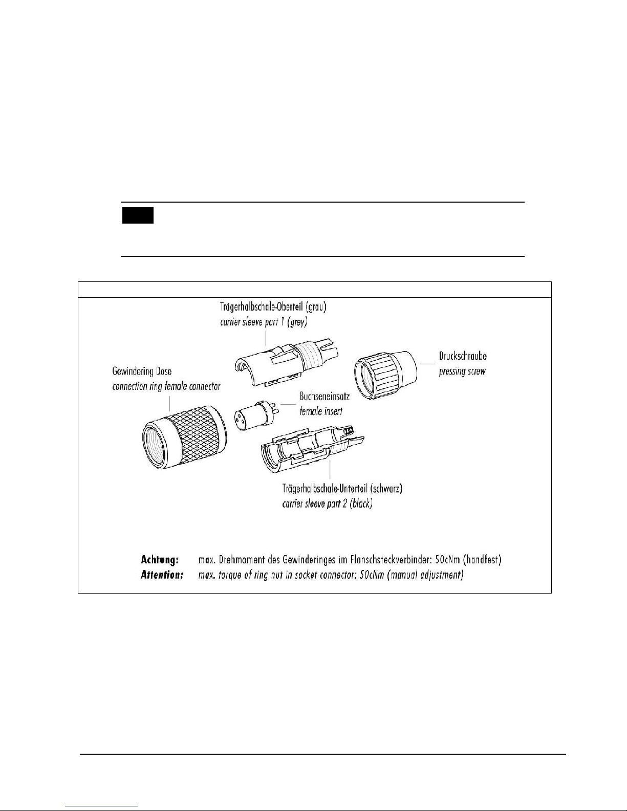
4.3 Electrical installation
The COMPACT WSC11 Weather Station is equipped with a 7-pin plug for electrical connection. A
cable socket (mating connector) is included in the scope of supply.
4.3.1 Cable, cable preparation, connector installation
The cable to be used for connection should have the following properties:
5 cores, core cross-section max. 0.14mm², cable diameter max. 5.0mm, resistant to ultraviolet rays,
overall shielding.
Note:
A prepared connecting cable is available for the COMPACT WSC11 Weather Station
as an optional accessory.
Cable socket, type: Binder, series 711
12 - 40 021774/07/14
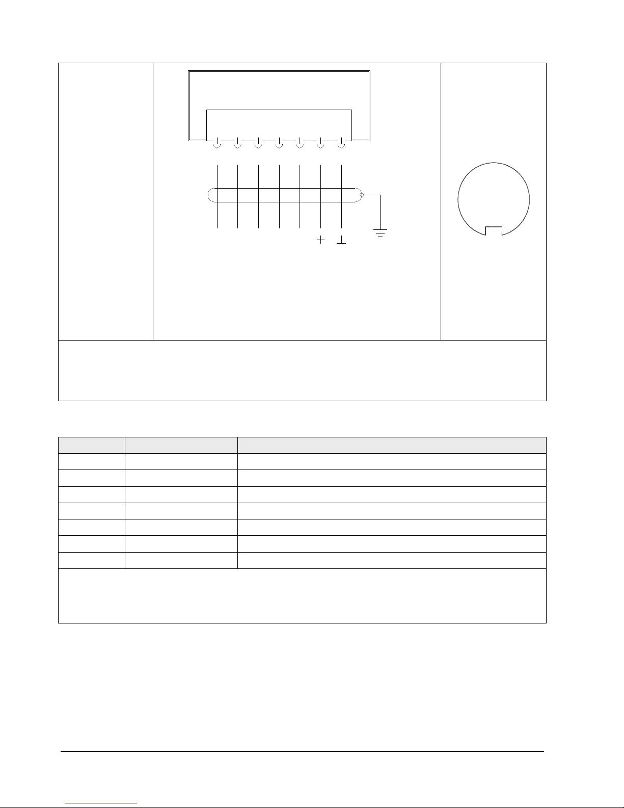
4.3.2 Diagram of connections
Order No.
4.9056.10.00x
View of
solder terminal
of mating connector
(cable socket)
2
4 6 3
5
1
7
* With long transmission paths connection to the GND of data acquisition may reduce their susceptibility to
interference.
Important:
* Do not connect DATA_GND to the supply voltage-GND.
4.3.3 Connection using cable 509 584 / 509 585 (optional accessory)
PIN
Core colour
Function
1
WHITE
NC 2 BROWN
* DATA _ GND
3
GREEN
DATA + 4 YELLOW
DATA -
5
GREY
NC
6
PINK
+ power 18...30V DC / 18...28V AC
7
BLUE
- power 18...30V DC / 18...28V AC
* With long transmission paths connection to the GND of data acquisition may reduce their susceptibility to
interference.
Important:
* Do not connect DATA_GND to the supply voltage-GND.
7 pol. Binder Steckverb. / Plug
7
Erde
Versorgung
DATA +
Earth
* DATA _ GND
Schirm / Shield
Power
18 ... 30 VDC
18 ... 28 VAC
DATA -
~
~
NC
NC
1 2 3 4 5 6

13 - 40 021774/07/14
5 Maintenance
As the device does not have any moving parts, i.e. is not subject to wear during operation, only
minimal servicing is required.
Depending on the location the instrument might pollute. The cleaning should be carried out by means
of water and a soft cloth. Aggressive cleaning agents must not be used.
Please note:
During storage, installation, de-installation, transport or
maintenance of the COMPACT WSC11 Weather Station make sure
that no water gets into the device or connector.

14 - 40 021774/07/14
6 Interface
The interface to the Weather Station consists of a RS485 link (half-duplex mode), with the following
data format:
9600baud (the baud rate can be selected with the Command BR).
8data bits.
No parity.
1stop bit.
Data in ASCII format (command interpreter: THIES).
Data in binary format (command interpreter: MODBUS RTU).
The behavior (configuration) of the Weather Station can be changed using the available commands
(see Commands and description). For the command interpreter Thies-type the query of the
measuring values is carried out by the Command TR or resp. by the Command TT.
When the Weather Station starts up, the character string "Weather Station", software version,
hardware version and serial number is output:
Weather Station
v03.04
508990 v11-11
12030123
6.1 Command interpreter THIES
The Weather Station is equipped with a command interpreter of THIES-type, which can be used to
change the behaviour of the device. This allows you for example to adjust the averaging periods for
wind speed and wind direction. Commands basically have the following structure:
<id><command><CR> (No parameter: used to interrogate the selected
parameter).
<id><command><parameter><CR> (With parameter: used to set a new parameter).
id: identification number ("00" to "99")
command: command encompassing 2 characters (see list of commands)
parameter: parameter value with between 1 to 10 positions (decimal value in ASCII format)
<CR>: carriage return (13
dec
; 0x0D)
The 'id' identification number allows several devices to be operated together in a bus system. Every
device is assigned its own 'id' (see Command ID), and automatic telegram output is switched off (see
Command TT).
A transmitted command is acknowledged with an echo telegram. The echo telegram starts with a "!"
followed by the id, command and value selected. It ends with the characters "carriage return" and "new
line".
Commands can be transmitted with or without a parameter. If no parameter is specified, the set value
will be output.
Example: 00BR<CR>
!00BR00005<CR>

15 - 40 021774/07/14
If a command is transmitted with a parameter, the parameter is verified. If it is valid, it will be saved and
specified in the echo telegram. If the parameter is invalid, it will be disregarded and the set value
output in the echo telegram.
Examples:
00BR00005<CR> transmission command
!00BR00005<CR> echo telegram (parameter valid and password OK)
00BR00004<CR> transmission command
!00BR00005<CR> echo telegram (parameter valid but key incorrect)
Note:
The values measured by the sensor can be queried with the command
TR.
In this case the Weather Station does not respond with the echo
telegram, but with the requested data telegram!
To avoid any unintentional change in parameters, some commands (see list of commands) are
protected with a password. This password must be transmitted before the actual command.
Example: Change baud rate
00KY234<CR> Release commands of user level
00BR4<CR> Set baud rate to 4800
!00BR00004<CR> Baud rate set to 4800
The Weather Station supports 3 different password levels.
User level (password: "234").
Calibration data level.
Administrator level.
Please note:
Password-protected commands are released as long as one of the
following conditions is satisfied:
- the supply voltage is switched
- command 00KY0<CR> is transmitted
- no new command is transmitted for min. 120s.
6.1.1 Data telegrams
Data output takes place in response to a request with the command TR. You can chose between the
following telegrams:
Measured value telegram (parameter=1).
Sensor data telegram (parameter=2).
Calculation of the checksum, the composition of the status word and the control characters/separators
used in the telegrams are described below.

16 - 40 021774/07/14
Control characters:
CR – Carriage return (13
dec
; 0x0D)
LF – Line feed (10
dec
; 0x0A)
STX – Start of text (2
dec
; 0x02)
ETX – End of text (3
dec
; 0x03)
Separators:
The semicolon ';' is used as the separator between the individual measured values in the string.
The checksum separator is the multiplication sign '*'.
Checksum:
The checksum is the XOR link of all characters between <STX> and the byte <*>.
The asterisk acts as the separator from the checksum and is no longer included in the checksum.
Status:
The Weather Station includes a status word (32-bit) which supplies information about the status of the
Weather Station. The measured values undergo a plausibility check and are shown in the status word.
Bit number
Function
Description
Bit 0
Precipitation sensor
=1, bedewing protection active.
Bit 1
Precipitation sensor
=1, drying phase of sensor surface.
Bit 2
GPS data
=1, no valid RMC telegram received.
Bit 3
RTC data from GPS
receiver
=1, time from GPS receiver invalid.
Bit 4
ADC values
=1, values from analog-digital-converter invalid.
Bit 5
Air pressure
=1, measured value from air pressure sensor invalid.
Bit 6
Brightness north
=1, measured value from brightness sensor north invalid.
Bit 7
Brightness east
=1, measured value from brightness sensor east invalid.
Bit 8
Brightness south
=1, measured value from brightness sensor south invalid.
Bit 9
Brightness west
=1, measured value from brightness sensor west invalid.
Bit 10
Twilight
=1, measured value for twilight invalid.
Bit 11
Global irradiance
=1, measured value from global irradiance sensor invalid.
Bit 12
Air temperature
=1, measured value from air temperature sensor invalid.
Bit 13
Precipitation
=1, measured value from precipitation sensor invalid.
Bit 14
Wind speed
=1, measured value from wind speed sensor invalid.
Bit 15
Wind direction
=1, measured value from wind direction sensor is invalid.
Bit 16
Humidity sensor
=1, Readings from the humidity sensor invalid (relative humidity,
absolute humidity, dew point temperature).
Bit 17
Watchdog Reset
=1, letzter Neustart durch Watchdog-Reset.
Bit 18
EEPROM Parameters
=1, internal EEPROM parameters invalid.
Bit 19
EEPROM Parameters
=1, internal EEPROM parameters contain the Standard-values.
Bit 20
New FW
=1, last restart was carried out with new firmware.
Table 1 : Status word

17 - 40 021774/07/14
6.1.1.1 Measured value telegram
The Weather Station responds to the command "00TR1\r" with the measured value telegram. The
telegram structure is given in the following table:
Position
Length
Example
Description
1 1 <STX>
Start of text characters (0x02).
2 3 WSC
Designates theWSC11 weather station.
5 1 ;
Semicolon.
6 2 ##
Identification number of weather station.
8 1 ;
Semicolon.
9
19
dd.mm.yyyy
hh:mm:ss
Date and time separated with a blank character
dd: day, mm: month, yyyy: year, hh: hour, mm: minute, ss: second.
28 1 ;
Semicolon.
29 6 ######
Specifies time format:
UTC
CEST
CET
UTC+xh
35 1 ;
Semicolon.
36 5 ###.#
Brightness north (kLux).
41 1 ;
Semicolon.
42 5 ###.#
Brightness east (kLux).
47 1 ;
Semicolon.
48 5 ###.#
Brightness south (kLux).
53 1 ;
Semicolon.
54 5 ###.#
Brightness west (kLux).
59 1 ;
Semicolon.
60 3 ###
Twilight (Lux).
63 1 ;
Semicolon.
64 4 ####
Global irradiance (W/m2).
68 1 ;
Semicolon.
69 5 ###.#
Air temperature (°C).
74 1 ;
Semicolon.
75 1 #
Precipitation status (0: no precipitation, 1: precipitation).
76 1 ;
Semicolon.
77 4 ##.#
Average1 wind speed (m/s).
81 1 ;
Semicolon.
82 3 ###
Average1 wind direction (°).
85 1 ;
Semicolon.
86 6 ####.#
Absolute air pressure (hPa).
92 1 ;
Semicolon.
93 6 ####.#
Relative air pressure (hPa), referred to height above sea level.
99 1 ;
Semicolon.
100 5 ###.#
Inside temperature of housing (°C).
105 1 ;
Semicolon.
106 5 ###.#
Relative humidity (% r.h.).
111 1 ;
Semicolon.
112 6 ###.##
Absolute humidity (g/m³).
118 1 ;
Semicolon.
119 5 ###.#
Dew-point temperature (°C).
124 1 ;
Semicolon.

18 - 40 021774/07/14
125
11
####.######
Degree of longitude (°) (GPS position)
Positive sign for longitude in eastern direction.
Negative sign for longitude in western direction.
135 1 ;
Semicolon.
136 1 ##.######
Degree of latitude (°) (GPS position).
137
10
###.######
Latitude (°) (GPS position).
Positive sign for latitude in northern direction.
Negative sign for latitude in southern direction.
147 1 ;
Semicolon.
148 5 ###.#
Position of the sun, elevation or resp. elevation angle (°).
On sunrise and sunset elevation equals 0°.
Between these distinctive points (i.e. intraday) the elevation takes
positive values.
153 1 ;
Semicolon.
154 5 ###.#
Position of the sun, azimuth or resp. geographic direction (°).
The azimuth is counted positively from the north to the south.
0° = north ; 180° = south.
159 1 ;
Semicolon.
160 8 ########
32-bit sensor status in hexadecimal format (0000 – FFFFFFFF).
168 1 *
Asterisk as separator for checksum.
169 2 ##
8-bit checksum in hexadecimal format (00 – FF). The checksum is
calculated from the exclusive OR link of all characters after STX to the
character before "*".
171 1 <ETX>
End of text characters (0x03).
172 1 <CR>
Carriage return (0x0D).
173 1 <LF>
Line feed (0x0A).
Table 2 : Measured value telegram
1
: The averaging interval is selected with the Command AI.
Measured values
The measured values are 1-second average values, with the exception of wind speed and wind
direction.
If the specified measuring range is exceeded (see Technical data), the measured value is limited to
the maximum (terminal value of measuring range) and the relevant bit set in the status (see table 1:
Status world).
Bit 16
Humidity sensor
=1, Readings from the humidity sensor invalid (relative humidity,
absolute humidity, dew point temperature).
Bit 17
Watchdog Reset
=1, letzter Neustart durch Watchdog-Reset.
Bit 18
EEPROM Parameters
=1, internal EEPROM parameters invalid.
Bit 19
EEPROM Parameters
=1, internal EEPROM parameters contain the Standard-values.
Bit 20
New FW
=1, last restart was carried out with new firmware.
Table 1 : Status word

19 - 40 021774/07/14
6.1.1.2 Sensor data telegram
The Weather Station responds to the command "00TR2\r" with the sensor data telegram. The telegram
structure is given in the following table:
Position
Length
Example
Description
1 1 <STX> 0x02
Start of text characters.
2
10
##########
Serial number.
12 1 ;
Semicolon.
13 5 ##-##
HW version (e.g. 06-11).
18 1 ;
Semicolon.
19 5 ##.##
SW version (e.g. 01.00).
24 1 ;
Semicolon.
25 6 ####.#
Height of Weather Station referred to height above sea level in
metres, derived from the GPS data (Geoid Model).
31 1 *
Asterisk as separator for the checksum.
32 2 ##
8-bit checksum in hexadecimal format (00 – FF). The checksum is
calculated from the exclusive OR link of all characters after STX to
the character before "*".
34 1 <ETX> 0x03
End of text characters.
35 1 <CR> 0x0D
Carriage return.
36 1 <LF> 0x0A
Line feed.
Table 3 : Sensor data telegram
6.2 Command interpreter MODBUS RTU
Once the command interpreter is selected the transmitted bytes are interpreted according to the
MODBUS specification (http://www.modbus.org/). Here, the weather station WSC11 is representing a
MODBUS Slave.
The data transmission is carried out in packages, so-called frames, of maximum 256 bytes. Each
package contains a 16bit CRC checksum (initial value: 0xffff).
Slave-Address
Function code
Data
CRC
1byte
1byte
0...252byte(s)
2bytes
CRC low-byte
CRC high-byte
Table 4 : MODBUS Frame
The following MODBUS functions are supported:
- 0x04 (Read Input Register).
- 0x03 (Read Holding Registers).
- 0x06 (Write Single Register).
- 0x10 (Write Multiple Registers).
The weather station WSC11 supports a write access for the slave-address 0 (“Broadcast”).
All received MODBUS request are checked for validity before carrying out. In error case the weather
station responds with one of the following exceptions (MODBUS Exception Responses).

20 - 40 021774/07/14
Code
Name
Signification
0x01
ILLEGAL FUNCTION
The function code in the request is not allowed for the
register address.
0x02
ILLEGAL DATA ADDRESS
The register address in the request is not valid.
0x03
ILLEGAL DATA VALUE
The stated data in the request are not allowed.
Table 5: MODBUS Exceptions
6.2.1 Measuring values (Input Register)
All measuring values of the weather station WSC11 consume 32Bit, i.e. 2 MODBUS register
addresses. The following table shows the allocation of measuring value to register address, while the
measuring values are sorted as follows:
- By measuring value type (30001 to 34999).
- In unbroken sequence (35001 to 39999).
Register
address
Parameter Name
Unit
Multiplicator
Explanation
Data
type
30001
Wind speed
m/s
10
value / 10
(1 decimal place, e.g. 101=10.1m/s)
U32
30003
Mean value
Wind speed
m/s
10
value / 10
(1 decimal place, e.g.. 101=10.1m/s)
U32 30201
Wind direction
°
10
value/ 10
(1 decimal place, e.g. 1010=101.0°)
U32
30203
Mean value
Wind direction
°
10
value / 10
(1 decimal place, e.g. 1010=101.0°)
U32
30401
Air temperature
°C
10
value / 10
(1 decimal place, e.g.
255=25.5°C)
S32
30403
Interior temperature of
housing
°C
10
value / 10
(1 decimal place, e.g.
355=35.5°C)
S32
30601
relative humidity
%r.h.
10
value/ 10
(1 decimal place, e.g. 355=35.5°r.F.)
U32
30603
absolute humidity
g/m³
100
value / 100
(2 decimal places, e.g.
923=9.23g/m^3)
U32
30605
Dew point temperature
°C
10
value / 10
(1 decimal place, e.g.
115=11.5°C)
S32
30801
Absolute air pressure
hPa
100
value / 100
(2 decimal places, e.g.
105000=1050.00hPa)
U32
30803
Relative air pressure
relating to NHN
hPa
100
value / 100
(2 decimal places, e.g.
105000=1050.00hPa)
U32

21 - 40 021774/07/14
31001
Global radiation
W/m²
10
value / 10
(1 decimal place, e.g
10000=1000.0W/m^2)
S32
31201
Brightness north
kLux
10
value / 10
(1 decimal place, e.g.
1200=120.0kLux)
U32
31203
Brightness east
kLux
10
value / 10
(1 decimal place, e.g.
1200=120.0kLux)
U32
31205
Brightness south
kLux
10
value / 10
(1 decimal place, e.g,
1200=120.0kLux)
U32
31207
Brightness west
kLux
10
value / 10
(1 decimal place, e.g.
1200=120.0kLux)
U32
31209
Twilight
Lux 1 value
(no decimal place, e.g. 500=500Lux)
U32
31401
Precipitation status
1 value
(no decimal place, (0=no
precipitation, 1=precipitation)
U32
34601
Date
1 value
(no decimal place,
JJJJMMTT, e.g.
20121210=10.12.2012)
U32
34603
Time
1 value
(no decimal place,
HHMMSS, e.g. 121035=12:10:35)
U32
34605
Time format
h 1 value
(no decimal place, offset to UTC in
hours, e.g. 60=UTC+1h)
S32
34801
Longitude
°
1000000
value / 1000000
(6 decimal places, e.g. )
S32
34803
Latitude
°
1000000
value/ 1000000
(6 decimal places, e.g. )
S32
34805
Sun position Elevation
°
10
value / 10
(1 decimal place, e.g. 900=90.0°)
S32
34807
Sun position Azimuth
°
10
value / 10
(1 decimal place, e.g. 1800=180.0° /
0°=north, 180°=south, clockwise
0…360°)
S32
34809
Height above sea level
m 1 value
(no decimal place, e.g. 240=240m
above sea level)
U32
34811
Sensor status
1 value
(no decimal place, bit coded, dep. of
sensor)
U32
34813
Main loop cycles per 1s
1/s 1 Value
(no decimal place, for ex.
2550=2550 1/s)
U32
34815
Operating time
s 1 Value
(no decimal place, for ex. 255=255s)
U32
34817
Mean value of the height
over MSL, received via
GPS.
m
10
Value
(1 decimal place, e.g.
240=24.0m above MSL)
U32

22 - 40 021774/07/14
35001
Wind speed
(30001)1
m/s
10
value / 10
(1 decimal place, e.g. 101=10.1m/s)
U32
35003
Mean value Wind speed
(30003) 1
m/s
10
value / 10
(1 decimal place, e.g. 101=10.1m/s)
U32
35005
Wind direction
(30201) 1
°
10
value/ 10
(1 decimal place, e.g. 1010=101.0°)
U32
35007
Mean value wind direction
(30203) 1
°
10
value / 10
(1 decimal place, e.g. 1010=101.0°)
U32
35009
Air temperature
(30401) 1
°C
10
value / 10
(1 decimal place, e.g. 255=25.5°C)
S32
35011
Interior temperature of
housing
(30403) 1
°C
10
Value / 10
(1 decimal place, e.g. 355=35.5°C)
S32
35013
Dew point temperature
(30605) 1
°C
10
value/ 10
(1 decimal place, e.g. 115=11.5°C)
S32
35015
Rel. humidity
(30601) 1
%r.h.
10
value / 10
(1 decimal place, e.g. 355=35.5°r.h.)
U32
35017
Abs. humidity
(30603) 1
g/m^3
100
value / 100
(2 decimal places, e.g.
923=9.23g/m^3)
U32
35019
Absolute air pressure
(30801) 1
hPa
100
value / 100
(2 decimal places, e.g.
105000=1050.00hPa)
U32
35021
Rel. air pressure relating
to sea level (30803) 1
hPa
100
value / 100
(2 decimal places, e.g.
105000=1050.00hPa)
U32
35023
Global radiation
(31001) 1
W/m^2
10
value / 10
(1 decimal place, e.g.
10000=1000.0W/m^2)
S32
35025
Brightness north
(31201) 1
kLux
10
value / 10
(1 decimal place, e.g.
1200=120.0kLux)
U32
35027
Brightness east
(31203) 1
kLux
10
value / 10
(1 decimal place, e.g.
1200=120.0kLux)
U32
35029
Brightness south
(31205) 1
kLux
10
value / 10
(1 decimal place, e.g.
1200=120.0kLux)
U32
35031
Brightness west
(31207) 1
kLux
10
value / 10
(1 decimal place, e.g.
1200=120.0kLux)
U32
35033
Twilight
(31209) 1
Lux 1 value
(no decimal place, e.g. 500=500Lux)
U32
35035
Precipitation status
(31401) 1
1 value
(no decimal place, (0=no
precipitation, 1=precipitation)
U32
35037
Date
(34601) 1
1 value
(no decimal place,
JJJJMMTT, e.g.
20121210=10.12.2012)
U32
35039
Time
(34603) 1
1 value
(no decimal place,
HHMMSS, e.g. 121035=12:10:35)
U32
35041
Time format
(34605) 1
h 1 value
(no decimal place, Offset to UTC in
hours, e.g. 60=UTC+1h)
S32
35043
Longitude
°
1000000
value / 1000000
S32

23 - 40 021774/07/14
(34801) 1
(6 decimal places, e.g. )
35045
Latitude
(34803) 1
°
1000000
value / 1000000
(6 decimal place, e.g. )
S32
35047
Sun position Elevation
(34805) 1
°
10
value / 10
(1 decimal place, e.g.
900=90.0°)
S32
35049
Sun position Azimuth
(34807) 1
°
10
value / 10
(1 decimal place, e.g.
1800=180.0° / 0°=north, 180°=south,
clockwise 0…360°)
S32
35051
Height above sea level
(34809) 1
m 1 Wert
(no decimal place, e.g.
240=240m above sea level)
U32
35053
Sensor status
(34811) 1
1 value
(no decimal place, bit coded, dep. of
sensor)
U32
35055
Main loop cycles
1/s 1 value
(no decimal place, number cycles
per 1s)
U32
35057
SHT2x temperature
°C
10
value / 10
(1 decimal place, e.g.
255=25.5°C)
S32
35059
NTC temperature
°C
10
value / 10
(1 decimal place, e.g.
255=25.5°C)
S32
35061
Operating time
s 1 Value
(no decimal place, for ex.
24000=24000s since last reset)
U32
35063
Mean value of the height
over MSL (34817)1,
received via GPS.
m
10
Value
(1 decimal place, e.g.
240=24.0m above MSL)
U32
Table 6 : MODBUS Input Register
1
: The numbers in parentheses describe the register addresses, which mean the same measuring value. Thus, the wind speed for ex. is
situated at address 30001 and at address 35001.
Remark:
Due to the unbroken sequence of the measuring values, starting
from address 35001, the MODBUS master can read-out all
measuring values by one request!

24 - 40 021774/07/14
6.2.2 Commands (Holding Register)
All commands of the weather station WSC11 consume 32Bit, i.e. 2 MODBUS register addresses, and
are representing unsigned integral numbers. The following example shows the changing of the baud
rate to 19200baud.
1. Set password for the user level (KY=234)
Slave
address
Function
code
Starting
address
Number
Registers
Number
byte(s)
Data
CRC
0x01
0x10
0x9C 49
0x00 02
0x04
0x00 00 00 EA
0x4F 7C
CRC
lowByte
CRC
high-Byte
2. Set command baud rate to 19200 baud (BR=6)
Slave
address
Function
code
Starting
address
Number
Registers
Number
byte(s)
Data
CRC
0x01
0x10
0x9C 45
0x00 02
0x04
0x00 00 00 06
0x4E A4
CRC
lowByte
CRC
high-Byte

25 - 40 021774/07/14
6.3 Commands and description
The following table lists the available commands and the associated passwords for read / write:
Command
Initial value
factory
setting
MODBUS
register-
address
Description
Password
Read1 / Write2
Command AI
10
40069
Averaging interval for wind speed and
wind direction.
None
User
Command BR
96
40005
Select baud rate.
None
User
Command CI
0
40013
Command interpreter.
None
User
Command DC
0
40081
Mode of calculation for twilight.
None
User
Command DO
0
40037
North correction of wind direction.
None
User
Command FB
1
40001
Quick-start mode.
None
User
Command ID
0 (THIES)
1 (MODBUS)
40003
Identification number resp. slave
address.
None
User
Command KY
0
40009
Set key / password.
None
None
Command LC
0
40045
LED control.
None
None
Command RS
-
40029
Reset.
None
User
Command SH
0
40071
Station height.
None
User
Command SV
-
45005
SW-Version.
None
-
Command TR
-
-
Telegram output.
None
None
Command TT
0
-
Automatic telegram output.
None
None
Command TZ
0
40073
Time zone.
None
User
Table 7 : List of commands
1
: Command without parameter (used to read selected parameter).
2
: Command with parameter (used to write a new parameter).
6.3.1 Command AI
<id>AI<parameter><CR> Averaging interval for wind speed and wind direction
Access: Read / write
Description: The command AI is used to specify the averaging interval for the wind
speed and wind direction in minutes.
The averaging of the wind velocity is scalar, and the averaging of the
wind direction vectorial.
If the parameter is 0, the averaging is deactivated, and the mean values
correspond to the instantaneous values. Here, the wind direction is reset
(to 0°) during calm (< 0.6m/s).
Wind from the North is displayed with 360°.
Parameter description: AI = 0 averaging disabled
AI = 1 averaging interval = 1 minute
Value range: 0...10
Initial value: 10

26 - 40 021774/07/14
6.3.2 Command BR
<id>BR<parameter><CR> Select baud rate
Access: Read / write
Description: The command BR is used to select the required baud rate.
Parameter description:
Parameter
Description
12
1200baud (8n1)
24
2400baud (8n1)
48
4800baud (8n1)
96
9600baud (8n1)
192
19200baud (8n1)
384
38400baud (8n1)
576
57600baud (8n1)
1152
115200baud (8n1)
Value range: 12 / 24 / 48 / 96 / 192 / 384 / 576 / 1152
Initial value: 96
6.3.3 Command CI
<id>CI<parameter><CR> Selection of command interpreter
Access: Read / write
Description: The requested command interpreter is set by command CL.
Remark:
If the identification number (ID) is > 98, it is set to 0 automatically
with the change-over to the THIES interpreter!
Remark:
If the identification number (ID) equals 0, a change-over to the
MODBUS-RTU-interpreter is not possible!
Parameter description:
Parameter
Description
0
THIES
1
MODBUS RTU
Value range: 0 to 1
Initial value: 0

27 - 40 021774/07/14
6.3.4 Command DC
<id>DC<parameter><CR> Mode of calculation for twilight
Access: Read/ write
Description: The mode of calculation for twilight is stated by command DC. The
twilight is calculated from the 4 brightness values, depending on direction.
Here, one can select between sum and mean value.
Parameter description: 0: Twilight corresponds to the sum of the 4 brightness values
1: Twilight corresponds to the mean value of the 4 brightness values
value rang: 0...1
Initial value: 0
6.3.5 Command DO
<id>DO<parameter><CR> North correction of wind direction
Access: Read / write
Description: The command DO is used to specify an offset for the wind direction
in °. This brings about correction to the north for the Weather Station.
Value range: 0…360
Initial value: 0
6.3.6 Command FB
<id>FB<parameter><CR> Quick-start mode
Access: Read / write
Description: The command FB is used to select quick-start mode.
Parameter description: 0: quick-start mode disabled
1: quick-start mode enabled
Value range: 0...1
Initial value: 1
6.3.7 Command ID
<id>ID<parameter><CR> Identification number
Access: Read / write
Description: This command is used to specify the identification number (THIES
interpreter) resp. the slave address (MODBUS RTU Interpreter). A
response telegram will only be transmitted if the 'id' in the command
matches the one set in the Weather Station. An exception here is the
generic 'id' that causes all weather stations to respond. Once the 'id' has
been changed, the device will immediately respond with the new 'id'.

28 - 40 021774/07/14
Parameter description: 99 generic 'id' (THIES interpreter)
0 Broadcast slave address (MODBUS RTU Interpreter)
Value range: 0 to 99 (THIES interpreter)
1 to 247 (MODBUS RTU interpreter)
Initial value: 0 (THIES Interpreter)
1 (MODBUS RTU Interpreter)
6.3.8 Command KY
<id>KY<parameter><CR> Key/password
Access: Read / write
Description: Through of the command “KY” the value for the key (password) is set. For
the change of parameters the required password must be used.
Parameter description: 0 no password
234 password for user level
Value range: 0 / 234
Initial value: 0
6.3.9 Command LC
<id>LC<parameter><CR> LED control
Access: Read / write
Description: The command LC is used to specify the mode for control of the blue LED.
Parameter description:
Parameter
Description
0
LED (blue) indicates wind speed
1
LED (blue) is dark
Examples:
LED dark blue: "00LC1\r"
LED blue indicates wind speed: "00LC0\r"
Value range: 0 / 1
Initial value: 0

29 - 40 021774/07/14
6.3.10 Command RS
<id>RS<parameter><CR> Reset
Access: Read / write
Description: Through the command RS a reset of the microcontroller is carried out.
The cause for the last reset is output without stating a parameter. Here,
the output occurs in the form of strings (see the following table), which are
lined up in a row, separated by spaces.
String
Description
PORF
Power On Reset Flag.
EXTRF
External Reset Flag.
BORF
Brownout Reset Flag.
WDRF
Watchdog Reset Flag.
PDIRF
Programming/Debug Interface Reset Flag.
SRF
Software Reset Flag.
SDRF
Spike Detector Reset Flag.
Parameter description: 1 Watchdog reset
2 Software reset
Value range: 1 / 2
Initial value: -
6.3.11 Command SH
<id>SH<parameter><CR> Station height
Access: Read / write
Description: The command is used to select the altitude at the location where the
Weather Station is installed.
This value is used to calculate the relative air pressure.
Height is specified in metres.
If the set parameter is 3001, the relative air pressure with elevation is
calculated from the GPS data.
Parameter description: Height above MSL in metres
0...3000: Station height in metres (the basis for calculation of the
relative air pressure)
3001: The parameter SH is disregarded (calculation of the
relative air pressure is based on the height from the GPS
data)
Value range: 0...3001

30 - 40 021774/07/14
Initial value: 0
Remark: GPS determines ellipsoidal heights above the reference ellipsoid
(==> World Geodetic System WGS84). From 36m (in Western
Pomerania) up to 50m (in the Black Forest and in the Alps) the ellipsoidal
heights in Germany are higher than the heavy-related heights (NN, HN,
NHN).
That means, there are regional elevation errors which can be avoided by
manual entry.
Moreover, it must be considered that the GPS altitude values can be
subject to a change of up to 30m (referred to the WGS8 ellipsoid)
6.3.12 Command SV
<id>SV<CR> SW-Version
Access: Read
Description: The software version can be read by means of command SV.
Parameter description: Response telegram: Value range: Initial value: -
6.3.13 Command TR
<id>TR<parameter><CR> Telegram output
Access: Read / write
Description: This command initiates one-off transmission of a telegram. The
parameter specifies the type of telegram.
Parameter description: 1 Measured value telegram.
2 Sensor data telegram.
Response telegram: See section 6.1.1
Value range: 1...2
Initial value: -

31 - 40 021774/07/14
6.3.14 Command TT
<id>TT <parameter><CR> Automatic telegram output
Access: Read / write
Description: The command TT is used to select the automatic output of telegrams
(interval = 1 second).
Automatic telegram output remains switched off for the first 10
seconds after start-up of the Weather Station. During this time the
user has the opportunity of changing the parameter TT.
Parameter description: 0 Automatic telegram output switched off.
1 Measured value telegram.
2 Sensor data telegram.
Response telegram: See section 6.1.1
Value range: 0...2
Initial value: 0
6.3.15 Command TZ
<id>TZ <parameter><CR> Time zone
Access: Read / write
Description: The command TZ is used to change the output of date/time.
Parameter description:: 0 UTC
23: UTC-Zeit – 1 hours
24: UTC-Zeit
25: UTC-Zeit + 1 hours
48: CEST or CET
The change between summer- and winter time occurs
independently.
TZ
Signification
0
UTC
1
UTC – 23 hours
...
...
24
UTC
...
-1
47
UTC + 23 hours
48
CEST or CET
Response telegram: Value range: 0...48
Initial value: 0

32 - 40 021774/07/14
7 LED signals
On the underside of the COMPACT WSC11 Weather Station there are 2 LEDs which are externally
visible through the housing.
Figure 1 : LEDs
If the Weather Station does not receive a command to query measured values for 3 seconds or longer,
the green LED flashes at a frequency of 1Hz and signals its readiness for operation. If automatic
telegram output is enabled (see Command TT), the green LED remains dark.
The flash frequency of the blue LED indicates the current wind speed (see Command LC). The
correlation between the flash frequency and wind speed is shown in the following figure:
0
5
10
15
20
25
30
35
40
0 5 10 15 20 25 30 35 40
Frequency [Hz]
WV [m/s]
Flash frequency of blue LED as a function of wind velocity
f = 0,9759*WG +
green LED
blue LED

33 - 40 021774/07/14
8 Technical data
Wind speed
Type
Thermal anemometer
Measuring range
0…40m/s
Resolution
0.1m/s
Accuracy
to 10m/s:
1m/s (rms - mean over 360°)
from 10m/s:
± 5 % (rms - mean over 360°)
Wind direction
Type
Thermal anemometer
Measuring range
1 … 360°
Resolution
1°
Accuracy with laminar incident
flow
± 10°
Brightness
Type
Silicon sensor
(north, east, south, west)
Measuring range
0…150kLux
Resolution
0.1kLux
Accuracy
± 3% (± 4.5kLux)
Spectral range
475...650nm
Twilight
Type
Silicon sensor
Measuring range
0…999Lux
Resolution
1Lux
Accuracy
± 10Lux
Global irradiance
Type
Silicon sensor
Measuring range
0…1300W/m
2
Resolution
1W/m2
Accuracy
± 10% (± 130W/m²)
Spectral range
350...1100nm
Precipitation
Type
Ceramics, capacitive value measurement,
sensor area heated
Measuring range
1 / 0 (precipitation yes/no)
Thermal output, sensor dry,
bedewing protection
0.1W
Thermal output, sensor wet
drying phase
1.1W
Temperature
Type
PT1000
Measuring range
-30 … +60°C
Resolution
0.1°C
Accuracy with wind speed >2m/s
± 1°C (-5°C…+25°C)

34 - 40 021774/07/14
Air pressure sensor
Type
Piezoresistive
Measuring range
300…1100hPa
Resolution
0.01hPa
Accuracy
± 0.5hPa at 20°C
Long-term stability
± 0.1hPa / year
Humidity sensor
Type
CMOS capacitive
Relative humidity
Measuring range
0…100% rel. humidity
Resolution
0.1% rel. humidity
Accuracy with wind speed >2m/s
± 10% rel. humidity at 20°C
Absolute humidity
measuring range
0...400g/m3
Resolution
0.01g/m3
Dew-point temperature
Measuring range
-30...+60°C
Resolution
0.1°C
Inside temperature of housing
Type
Silicon sensor
Measuring range
-30 … +60°C
Resolution
0.1°C
Accuracy
± 2°C
Digital interface
Type
RS485
Mode
Half-duplex mode
Baud rate
1200, 2400, 4800, 9600, 19200, 38400,
57600, 115200
Data format
- ASCII (command interpreter: THIES)
- Binary (command interpreter: MODBUS
RTU)
General
Operating voltage
18...30VDC, 18...28VAC
Power consumption
< 300mA at 24VDC
Ambient conditions
Temperature range
-30... +60 °C
Humidity range
Non-condensing
GPS reception
GPS receiver with low power
consumption, built-in RTC and
antenna
Holding time of RTC (without
voltage supply)
Approx. 3 days
Housing
Material
Polycarbonate
Dimensions
See Dimension drawing
Weight
0.22kg
Type of protection
IP65 in working position
Type of connection
7-pin plug connector

35 - 40 021774/07/14
Figure 2 : Spectrum of brightness sensors
(Source: data sheet for component SFH5711 / OSRAM)
Figure 3 : Directional characteristics of brightness sensors
(Source: data sheet for component SFH5711 / OSRAM)

36 - 40 021774/07/14
Figure 4 : Spectrum for global irradiance sensor
(Source: data sheet for component TEMD5080X01 / VISHAY)
9 Dimension drawing [in mm]
Srew M4
Allen key size 2 mm
Plug connection
Mast holder

37 - 40 021774/07/14
10 Accessories (optional)
Cable
Prepared connecting cable for
COMPACT WSC11 Weather
Station.
Features:
Cable with cable socket on
device side and open ends on
reception side.
Article No. 509 584
Article No. 509 585
Length: 5m
Length: 10m
Device Utility Tool
Article No. 9.1700.81.000
Cost-free tool for parameter settings
and/or special configurations.
Please send a short e-mail to
info@thiesclima.com, keyword “Utility
Tool WSC 11” in the subject heading,
as well as your sender information
and our order number / invoice
number.We will then let you have
your log-in for the download.
Installation support
Used for lateral attachment of
COMPACT WSC11 Weather
Station to a vertical surface.
Article No. 509564
Length: 250mm
Width: 60mm
Material: Stainless steel 1.4301

38 - 40 021774/07/14
11 EC-Declaration of Conformity
Document-No.: 002002 Month: 07 Year: 14
Manufacturer: A D O L F T H I E S G m b H & C o. K G
Hauptstr. 76
D-37083 Göttingen
Tel.: (0551) 79001-0
Fax: (0551) 79001-65
email: Info@ThiesClima.com
Description of Product: Weatherstation, Weatherstation Compact WSC11
Article No.
4.9055.00.000
4.9056.00.000
4.9056.00.001
4.9056.10.000
4.9056.10.001
specified technical data in the document:
021704/08/13; 021773/07/14
The indicated products correspond to the essential requirement of the following European Directives and Regulations:
2004/108/EC DIRECTIVE 2004/108/EC OF THE EUROPEAN PARLIAMENT AND OF THE COUNCIL
of 15 December 2004 on the approximation of the laws of the Member States relating to electromagnetic
compatibility and repealing Directive 89/336/EEC
2006/95/EC DIRECTIVE 2006/95/EC OF THE EUROPEAN PARLIAMENT AND OF THE COUNCIL
of 12 December 2006 on the harmonisation of the laws of Member States relating to electrical equipment
designed for use within certain voltage limits
552/2004/EC Regulation (EC) No 552/2004 of the European Parliament and the Council of 10 March 2004
on the interoperability of the European Air Traffic Management network (the interoperability Regulation)
2011/65/EU DIRECTIVE 2011/65/EU OF THE EUROPEAN PARLIAMENT AND OF THE COUNCIL
of 8 June 2011 on the restriction of the use of certain hazardous substances in electrical
and electronic equipment
The indicated products comply with the regulations of the directives. This is proved by the compliance with the following
standards:
Reference number
Specification
IEC 61000-6-2: 2005
Electromagnetic compatibility
Immunity for industrial environment
IEC 61000-6-3: 2006
Electromagnetic compatibility
Emission standard for residential, commercial and light industrial environments
IEC 61010-1: 2010
Safety requirements for electrical equipment for measurement, control, and
laboratory use. Part 1: General requirements
Place: Göttingen Date: 21.07.2014
This declaration certificates the compliance with the mentioned directives, however does not include any warranty of characteristics.
Please pay attention to the security advises of the provided instructions for use.

39 - 40 021774/07/14

40 - 40 021774/07/14
Official BeNeLux distributor: www.catec.nl
- Alterations reserved -
 Loading...