

catec 7.1414.60.000, 7.1414.60.040, 7.1414.60.041, 7.1414.61.000, 7.1414.61.040 Instructions For Use Manual
...
Instruction for use
021505/04/11
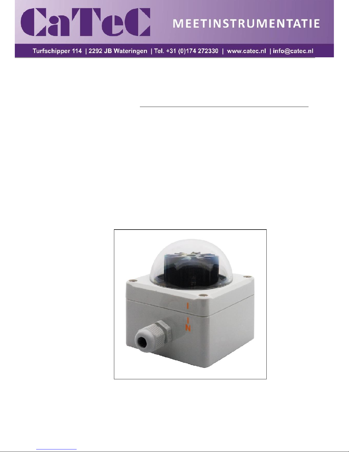
Brightness Transmitter
7.1414.6x.0xx

2 - 14 021505/04/11
Contents
1 Models ....................................................................................................................................... 3
2 Application ................................................................................................................................. 3
3 Mode of Operation ..................................................................................................................... 3
4 Installation ................................................................................................................................. 6
4.1 Mechanical Mounting ........................................................................................................... 6
4.1.1 Examples for Mounting Alternatives .............................................................................. 7
4.2 Electrical Mounting .............................................................................................................. 8
4.3 Setting of the Heating Device .............................................................................................. 8
5 Maintenance .............................................................................................................................. 8
6 Connecting Diagrams ................................................................................................................ 9
7 Technical Data ......................................................................................................................... 10
8 Dimensional Drawing ............................................................................................................... 11
9 Diagram – Heating ................................................................................................................... 11
10 EC-Declaration of Conformity ............................................................................................... 12
Figures
Figure 1: Horizontal (Azimuth) direction-dependency of the brightness with model 7.1414.60.0xx ... 5
Figure 2: Horizontal (Azimuth) direction-dependency of the brightness with model 7.1414.61.0xx ... 5
Figure 3: North marking ................................................................................................................... 6
3 - 14 021505/04/11
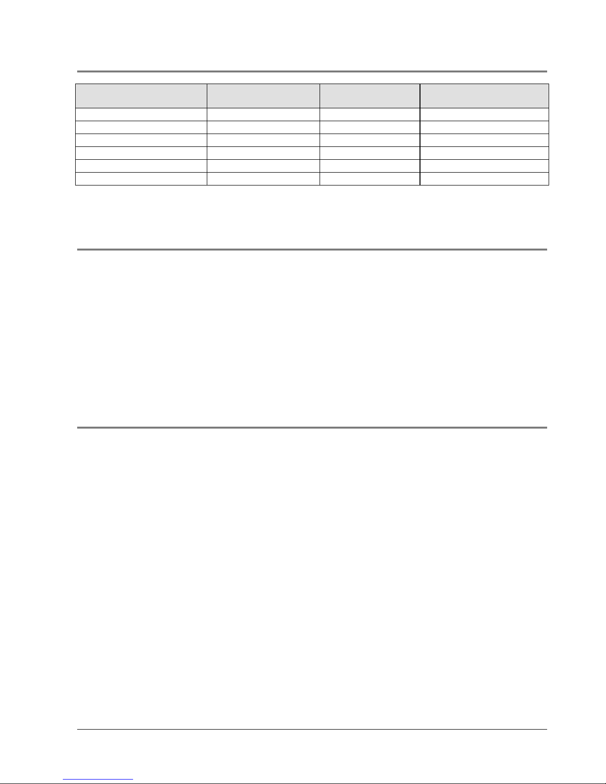
1 Models
Order-No.
Meas. Range
Elect. -Output
Numbers of Sectors
and Outputs
7.1414.60.000
0...100 000 Lux
0...10 V 8 7.1414.60.040
0...100 000 Lux
0…20 mA
8
7.1414.60.041
0...100 000 Lux
4…20 mA
8
7.1414.61.000
0...100 000 Lux
0...10 V 3 7.1414.61.040
0...100 000 Lux
0...20 mA 3 7.1414.61.041
0...100 000 Lux
4...20 mA
3
2 Application
The brightness transmitter serves for the acquisition of sun position-dependent intensities of the
daylights. The physical measuring values are output as light-proportional voltages or currents, and are
used, for ex. for sun position-dependent control of shading devices, heating- and irrigation plants.
The measuring value “brightness” of the model 7.1414.60.0xx is acquired by eight independent
sensors (photo diodes) which are arranged in 45°-segments (North, NE, East, SE, South, SW,
West, NW).
The measuring value “brightness” of the model 7.1414.61.0xx is acquired by three independent
sensors (photo diodes) which are arranged in 90°-segments (East, South, West).
3 Mode of Operation
Brightness Transmitter 7.1414.60.0xx :
By means of eight sensors (photo diodes), and the connected electronics the incident light is
transformed into eight proportional output values, which are linear to the brightness. Each electrical
output corresponds to a sector of 45° degrees. The sectors are centrally related to the directions.
1. Sector: North = 337,5° - 22,5°
2. Sector: NE = 22,5° - 67,5°
3. Sector: East = 67,5° - 112,5°
4. Sector: SE = 112,5° - 157,5°
5. Sector: South = 157,5° - 202,5°
6. Sector: SW = 202,5° - 247,5°
7. Sector: West = 247,5° - 292,5°
8. Sector: NW = 292,5° - 337,5°

4 - 14 021505/04/11
Brightness Transmitter 7.1414.61.0xx :
By means of three sensors (photo diodes), and the connected electronics the incident light is
transformed into eight proportional output values, which are linear to the brightness. Each electrical
output corresponds to a sector of 90° degrees. The sectors are centrally related to the directions
1. Sector: East = 45° - 135°
2. Sector: South = 135° - 225°
3. Sector: West = 225° - 315°
Remark:
The sensors (photodiodes) acquire the brightness related to a vertical surface.
In order to avoid a possible dewing the brightness transmitters are equipped with a
heating device.
Note: for Brightness Transmitter with voltage output 7.1414.6x.000 :
A parallel connection of the outputs is possible. Thereby, free selectable acquisition
ranges can be generated by more than one direction elements (for ex. monitoring
ranges from N+NE+E). The highest value is delivered at the shared output.

5 - 14 021505/04/11
Figure 1: Horizontal (Azimuth) direction-dependency of the brightness with model 7.1414.60.0xx
Figure 2: Horizontal (Azimuth) direction-dependency of the brightness with model 7.1414.61.0xx
North
West
South
East
East
0
0,1
0,2
0,3
0,4
0,5
0,6
0,7
0,8
0,9
1
0°
10°
20°
30°
40°
50°
60°
70°
80°
90°
100°
110°
120°
130°
140°
150°
160°
170°
180°
190°
200°
210°
220°
230°
240°
250°
260°
270°
280°
290°
300°
310°
320°
330°
340°
350°
North
South
West

6 - 14 021505/04/11
4 Installation
Remark:
When mounting the instrument, please take into consideration that the sensor
valuates also reflected light, and accumulates it to the direct incident sun light. At
locations with reflecting surfaces the measuring values are considerably higher than
they would be in the free field, or in front of a hardly reflecting surface.
The instrument must not be installed in the shades of buildings, parts of buildings,
masts, antennas, trees, bushes etc., as otherwise the proper ambient brightness or
the direct sun radiation is not acquired correctly.
Attention:
The electrical connection must be carried out only by a qualified
expert.
The instrument must be opened only in dry conditions.
The uncovered electronics must not be damaged.
4.1 Mechanical Mounting
The brightness transmitter is designed to be mounted to a horizontal surface out-of-doors. It is
recommended to carefully choose a location which is free of shades and reflections.
For installation please unscrew and remove the housing cover. Through the now accessible mounting
boreholes the instrument is fastened by the respective screws.
For the optimum acquisition of the sun position the brightness transmitter is aligned by means of a
compass, so that the side of the housing with the north marking indicates to the (geographical)
Northern direction.
Figure 3: North marking

7 - 14 021505/04/11
4.1.1 Examples for Mounting Alternatives
Mounting of the brightness transmitter at a mast top through holder, and adaptor.
Mounting of the brightness transmitter below a mast top through traverse and adaptor.
In order to minimize reflections it is recommended to blacken the mast, above the traverse,
acc. to the length of the traverse.
Remark:
Mast, holder, traverse, and adapter are not included in delivery
Adapter
Order-No.. 506345
Brightness Transmitter
Order-No. 7.1414.6x.0xx
Mast
Holder –compact
Order-No. 506347
45°
Mast
Traverse –compact
Order-No.4.3171.40.000
Adapter
Order-No. 506345
Brightness Transmitter
Order-No. 7.1414.6x.0xx
North direction

8 - 14 021505/04/11
4.2 Electrical Mounting
Use a shielded LiYCY 12 x 0,25 mm² (6 x 0,25 mm²) cable to connect the instrument electrically. Lead
the cable through the screwed cable gland and place it on the terminal strip as shown in the
connecting diagram. Ground the shielding.
After wiring of the instrument the nut of the cable gland, and screws of the housing cover are to be
screwed tightly together with the base part of the housing.
4.3 Setting of the Heating Device
On status of delivery the heating is activated. In case a deactivation should be carried out please
unscrew and remove the housing cover. Open the bridge P4 on the pc-board which is now visible.
5 Maintenance
Clean the light dome at regular intervals – depending on the extent of soiling – with a soft cloth and
pure water (no additives).
+Vers.
GND
Ost
NO
GND
IN
OUT
Nord
SüdWest SOSWNWGND
OUT
P4
65
4
321
~~
78910
1112
Nordseite
Lötbrücke für
Heizung ON

9 - 14 021505/04/11
6 Connecting Diagrams
Order-No.
7.1414.60.000
7.1414.60.040
7.1414.60.041
Versorgung
12 ... 28 V DC
24V AC
Power
1 2 3 4 5 6
2 x 6 pin Klemmleiste / Clamp connector
Brücke / Bridge
NNENOEO GND
8 x Ausgang / Output 0 ... 10 V ; 0/4 ... 20 mA
8 x Helligkeit / Brightness 0 ... 100 k Lux
Leiterplatte / PC board
M16x1,5
Ø 4,5 - 9 mm
Kabel / Cable
Helligkeitsgeber , 8 Sektoren
Brightness Transmitter , 8 Sectors
N = Nord / North
NO = Nord-Ost / North-East
O = Ost / East
SO = Süd-Ost / South-East
S = Süd / South
SW = Süd-West / South-West
W = West
NW = Nord-West / North-West
7 8 9 10 11 12
SW
W S
SE
SO
NW
GND
Erde
Earth
Order-No.
7.1414.61.000
7.1414.61.040
7.1414.61.041
Versorgung
12 ... 28 V DC
24V AC
Power
1 2 3 4 5 6
6 pin Klemmleiste / Clamp connector
O SEW GND
3 x Ausgang / Output 0 ... 10 V ; 0/4 ... 20 mA
3 x Helligkeit / Brightness 0 ... 100 k Lux
Leiterplatte / PC board
M16x1,5
Ø 4,5 - 9 mm
Kabel / Cable
Helligkeitsgeber , 3 Sektoren
Brightness Transmitter , 3 Sectors
O = Ost / East
S = Süd / South
W = West
Erde
Earth

10 - 14 021505/04/11
7 Technical Data
Measuring range
0 ... 100 kLux
Sensor
SFH 206 K
Spectral range
400... 1100 nm
Accuracy
2% of measuring range with vertical light incidence on
the photodiode
Acquisition angel with 7.1414.60.000
Elevation
Azimuth
0... 90°
8 x ± 22,5°
Acquisition angel with 7.1414.61.000
Elevation
Azimuth
0... 90°
3 x ± 45°
Electrical output
7.1414.6x.000
7.1414.6x.040
7.1414.6x.041
The outputs are shortcut-safe. The outputs can be
connected in parallel
0...10 V per Sector; voltage- limited to < 10,5 V
0...20 mA per Sector; current limited to < 20,5 mA
4...20 mA per Sector; current limited to < 20,5 mA
Operating voltage
12...28 VDC / 24VAC
Load resistance 7.1414.6x.000
Load 7.1414.6x.04x
≥ 1000 Ω
< 350 Ω
Operating current 7.1414.6x.000
7.1414.60.04x
7.1414.61.04x
ca. 10 mA w/o heating (w/o signal currents)
max. 250 mA with heating
< 170 mA w/o heating (= 10 mA + 8x Iout)
< 400 mA with heating
< 70 mA w/o heating (= 10 mA + 3x Iout)
< 300 mA with heating
Ambient temperature
- 30...+ 70° C
Protection
IP 65
Weight
150g
Connection
Screwed cable gland and clamp connector

11 - 14 021505/04/11
8 Dimensional Drawing
96
50
80
70
82
55
Montagebohrungen Ø 4 mm
Kabelverschraubung M16 x 1,5
für Kabeldurchmesser 4,5...10 mm
9 Diagram – Heating
0,0
2,0
4,0
6,0
8,0
10,0
12,0
14,0
16,0
-30 -20 -10 0 10 20 30
outside air temperature [ °C ]
temperature rise inside [ K ]
Inside - outside – difference
temperature by using the heating.
When the outside temperature
is falling the heating capacity
raises.
At a power supply of 24 V the
heating current is flowing as
follows
+30°C approx. 20 mA
–30 °C approx. 140 mA
The raised inside temperature
prevents the light dome from
being moistened by dew.
Mounting bore hole 4 mm
Cable gland M16 x 1.5 , 4,5-10

12 - 14 021505/04/11
10 EC-Declaration of Conformity
Document-No.: 000318 Month: 04 Year: 11
Manufacturer: A D O L F T H I E S G m b H & C o. K G
Hauptstr. 76
D-37083 Göttingen
Tel.: (0551) 79001-0
Fax: (0551) 79001-65
email: Info@ThiesClima.com
Description of Product: Brightness Transmitter
Article No.
7.1414.10.003
7.1414.10.040
7.1414.10.041
7.1414.10.061
7.1414.10.541
7.1414.10.561
7.1414.10.941
7.1414.12.040
7.1414.12.041
7.1414.12.061
7.1414.15.040
7.1414.15.041
7.1414.15.061
7.1414.22.040
7.1414.22.041
7.1414.22.061
7.1414.25.040
7.1414.25.041
7.1414.25.061
7.1414.40.002
7.1414.40.102
7.1414.40.103
7.1414.40.112
7.1414.40.141
7.1414.40.152
7.1414.51.150
7.1414.51.550
7.1414.60.000
7.1414.60.040
7.1414.60.041
7.1414.60.500
7.1414.61.000
7.1414.61.040
7.1414.61.041
specified technical data in the document:
020923/05/07; 021316/05/07; 021327/05/10; 021524/05/07;
021458/04/11; 021601/12/09; 021630/02/10
The indicated products correspond to the essential requirement of the following European Directives and Regulations:
2004/108/EC DIRECTIVE 2004/108/EC OF THE EUROPEAN PARLIAMENT AND OF THE COUNCIL
of 15 December 2004 on the approximation of the laws of the Member States relating to electromagnetic
compatibility and repealing Directive 89/336/EEC
2006/95/EC DIRECTIVE 2006/95/EC OF THE EUROPEAN PARLIAMENT AND OF THE COUNCIL
of 12 December 2006 on the harmonisation of the laws of Member States relating to electrical equipment
designed for use within certain voltage limits
552/2004/EC Regulation (EC) No 552/2004 of the European Parliament and the Council of 10 March 2004
on the interoperability of the European Air Traffic Management network
(the interoperability Regulation)
The indicated products comply with the regulations of the directives. This is proved by the compliance with the following
standards:
Reference number
Specification
IEC 61000-6-2: 2005
Electromagnetic compatibility
Immunity for industrial environment
IEC 61000-6-3: 2006
Electromagnetic compatibility
Emission standard for residential, commercial and light industrial environments
IEC 61010-1: 2001
Safety requirements for electrical equipment for measurement, control and
laboratory use. Part 1: General requirements
Place: Göttingen Date: 21.04.2011
This declaration certificates the compliance with the mentioned directives, however does not include any warranty of characteristics.
Please pay attention to the security advises of the provided instructions for use.

13 - 14 021505/04/11
Official BeNeLux distributor: www.catec.nl
- Alterations reserved -
 Loading...