

catec 7.1414.60.000, 7.1414.60.040, 7.1414.60.041, 7.1414.61.000, 7.1414.61.040 Instructions For Use Manual
...
Instruction for use
021505/04/11
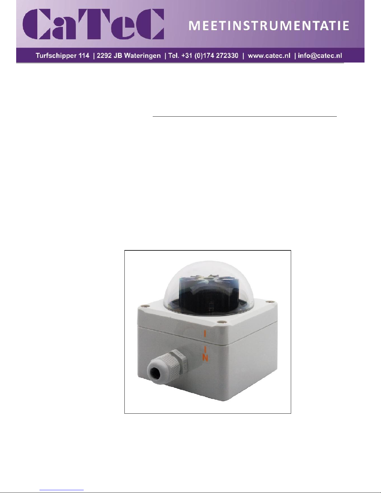
Brightness Transmitter
7.1414.6x.0xx

2 - 14 021505/04/11
Contents
1 Models ....................................................................................................................................... 3
2 Application ................................................................................................................................. 3
3 Mode of Operation ..................................................................................................................... 3
4 Installation ................................................................................................................................. 6
4.1 Mechanical Mounting ........................................................................................................... 6
4.1.1 Examples for Mounting Alternatives .............................................................................. 7
4.2 Electrical Mounting .............................................................................................................. 8
4.3 Setting of the Heating Device .............................................................................................. 8
5 Maintenance .............................................................................................................................. 8
6 Connecting Diagrams ................................................................................................................ 9
7 Technical Data ......................................................................................................................... 10
8 Dimensional Drawing ............................................................................................................... 11
9 Diagram – Heating ................................................................................................................... 11
10 EC-Declaration of Conformity ............................................................................................... 12
Figures
Figure 1: Horizontal (Azimuth) direction-dependency of the brightness with model 7.1414.60.0xx ... 5
Figure 2: Horizontal (Azimuth) direction-dependency of the brightness with model 7.1414.61.0xx ... 5
Figure 3: North marking ................................................................................................................... 6

3 - 14 021505/04/11
1 Models
Order-No.
Meas. Range
Elect. -Output
Numbers of Sectors
and Outputs
7.1414.60.000
0...100 000 Lux
0...10 V 8 7.1414.60.040
0...100 000 Lux
0…20 mA
8
7.1414.60.041
0...100 000 Lux
4…20 mA
8
7.1414.61.000
0...100 000 Lux
0...10 V 3 7.1414.61.040
0...100 000 Lux
0...20 mA 3 7.1414.61.041
0...100 000 Lux
4...20 mA
3
2 Application
The brightness transmitter serves for the acquisition of sun position-dependent intensities of the
daylights. The physical measuring values are output as light-proportional voltages or currents, and are
used, for ex. for sun position-dependent control of shading devices, heating- and irrigation plants.
The measuring value “brightness” of the model 7.1414.60.0xx is acquired by eight independent
sensors (photo diodes) which are arranged in 45°-segments (North, NE, East, SE, South, SW,
West, NW).
The measuring value “brightness” of the model 7.1414.61.0xx is acquired by three independent
sensors (photo diodes) which are arranged in 90°-segments (East, South, West).
3 Mode of Operation
Brightness Transmitter 7.1414.60.0xx :
By means of eight sensors (photo diodes), and the connected electronics the incident light is
transformed into eight proportional output values, which are linear to the brightness. Each electrical
output corresponds to a sector of 45° degrees. The sectors are centrally related to the directions.
1. Sector: North = 337,5° - 22,5°
2. Sector: NE = 22,5° - 67,5°
3. Sector: East = 67,5° - 112,5°
4. Sector: SE = 112,5° - 157,5°
5. Sector: South = 157,5° - 202,5°
6. Sector: SW = 202,5° - 247,5°
7. Sector: West = 247,5° - 292,5°
8. Sector: NW = 292,5° - 337,5°

4 - 14 021505/04/11
Brightness Transmitter 7.1414.61.0xx :
By means of three sensors (photo diodes), and the connected electronics the incident light is
transformed into eight proportional output values, which are linear to the brightness. Each electrical
output corresponds to a sector of 90° degrees. The sectors are centrally related to the directions
1. Sector: East = 45° - 135°
2. Sector: South = 135° - 225°
3. Sector: West = 225° - 315°
Remark:
The sensors (photodiodes) acquire the brightness related to a vertical surface.
In order to avoid a possible dewing the brightness transmitters are equipped with a
heating device.
Note: for Brightness Transmitter with voltage output 7.1414.6x.000 :
A parallel connection of the outputs is possible. Thereby, free selectable acquisition
ranges can be generated by more than one direction elements (for ex. monitoring
ranges from N+NE+E). The highest value is delivered at the shared output.
 Loading...