

Page 1
查询CAT5259JI-00TE13供应商
CAT5259
Quad Digitally Programmable Potentiometers (DPP™)
with 256 Taps and 2-wire Interface
FEATURES
N
E
G
F
O
R
L
A
H
L
E
A
E
E
E
E
TM
R
D
F
■ Four linear taper digitally programmable
potentiometers
■ 256 resistor taps per potentiometer
■ End to end resistance 50k
ΩΩ
Ω or 100k
ΩΩ
ΩΩ
Ω
ΩΩ
■ Potentiometer control and memory access via
2-wire interface (I2C like)
■ Low wiper resistance, typically 100
■ Nonvolatile memory storage for up to four
ΩΩ
Ω
ΩΩ
wiper settings for each potentiometer
DESCRIPTION
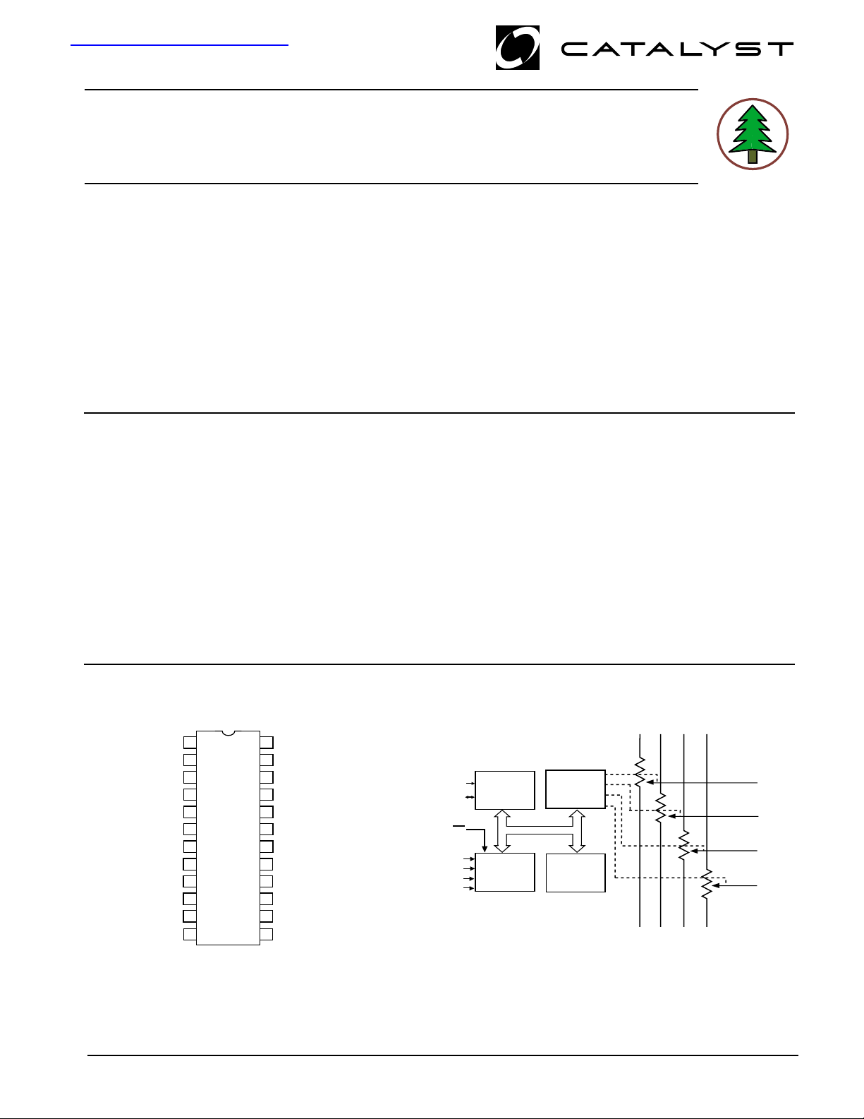
The CAT5259 is four digitally programmable
potentiometers (DPPs™) integrated with control logic
and 16 bytes of NVRAM memory. Each DPP consists of
a series of resistive elements connected between two
externally accessible end points. The tap points between
each resistive element are connected to the wiper outputs
with CMOS switches. A separate 8-bit control register
(WCR) independently controls the wiper tap switches for
each DPP. Associated with each wiper control register
are four 8-bit non-volatile memory data registers (DR)
used for storing up to four wiper settings. Writing to the
wiper control register or any of the non-volatile data
■ Automatic recall of saved wiper settings at
power up
■ 2.5 to 6.0 volt operation
■ Standby current less than 1 µA
■ 1,000,000 nonvolatile WRITE cycles
■ 100 year nonvolatile memory data retention
■ 24-lead SOIC and 24-lead TSSOP packages
■ Industrial temperature range
registers is via a 2-wire serial bus. On power-up, the
contents of the first data register (DR0) for each of the
four potentiometers is automatically loaded into its
respective wiper control registers.
The CAT5259 can be used as a potentiometer or as a
two terminal, variable resistor. It is intended for circuit
level or system level adjustments in a wide variety of
applications. It is available in the 0˚C to 70˚C commercial
and -40˚C to 85˚C industrial operating temperature
ranges and offered in a 24-lead SOIC and TSSOP
package.
PIN CONFIGURATION
SOIC/TSSOP Package (J, W/U, Y)
CAT
5259
24
23
22
21
20
19
18
17
16
15
14
13
1
NC
2
A0
W3
H3
L3
NC
CC
L0
H0
W0
A2
WP
3
4
5
6
7
8
9
10
11
12
R
R
R
V
R
R
R
© 2004 by Catalyst Semiconductor, Inc.
Characteristics subject to change without notice
A3
SCL
RL2
RH2
R
W2
NC
GND
R
W1
R
H1
R
L1
A1
SDA
FUNCTIONAL DIAGRAM
SCL
2-WIRE BUS
INTERFACE
SDA
WP
A0
CONTROL
A1
LOGIC
A2
A3
1
WIPER
CONTROL
REGISTERS
NONVOLATILE
DATA
REGISTERS
R
H0
R
L0
R
R
R
H2
H1
R
L1
H3
R
R
L2
L3
Document No. 2000, Rev. F
R
W0
R
W1
R
W2
R
W3
Page 2
CAT5259
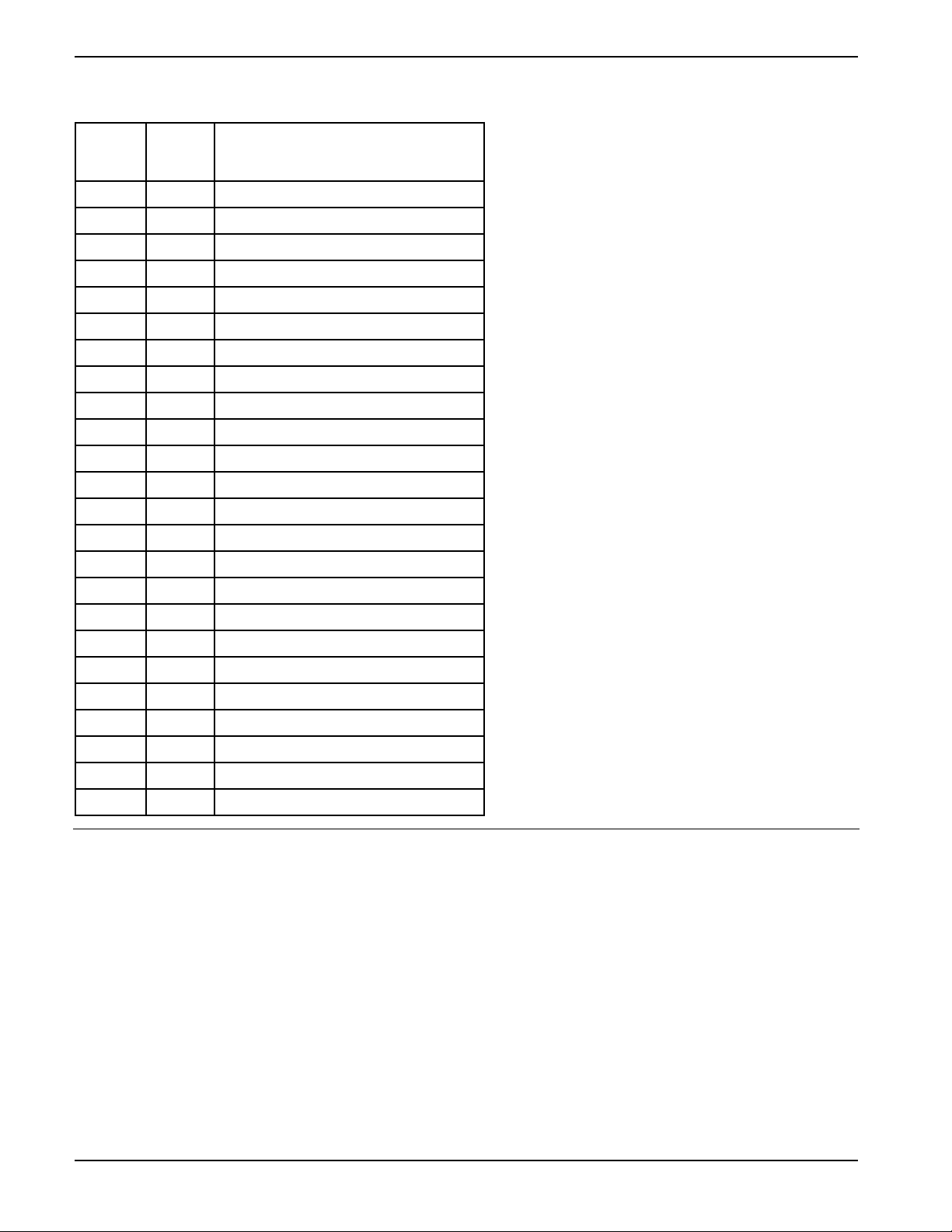
PIN DESCRIPTION
niP
/CIOS(
)POSST
1CNtcennoCoN
20ABSL,sserddAeciveD
33WR3retemoitnetoProflanimreTrepiW
43HR3retemoitnetoProflanimreTecnerefeRhgiH
53LR3retemoitnetoProflanimreTecnerefeRwoL
6CNtcennoCoN
7CCVegatloVylppuS
80LR0retemoitnetoProflanimreTecnerefeRwoL
90HR0retemoitnetoProflanimreTecnerefeRhgiH
010WR0retemoitnetoProflanimreTrepiW
112AsserddAeciveD
21
31ADStuptuO/tupnIataDlaireS
411AsserddAeciveD
511LR1retemoitnetoProflanimreTecnerefeRwoL
611HR1retemoitnetoProflanimreTecnerefeRhgiH
711WR1retemoitnetoProflanimreTrepiW
81DNGdnuorG
91CNtcennoCoN
022WR2retemoitnetoProflanimreTrepiW
122HR2retemoitnetoProflanimreTecnerefeRhgiH
222LR2retemoitnetoProflanimreTecnerefeRwoL
32LCSkcolClaireSsuB
423AsserddAeciveD
emaNnoitcnuF
PW
PIN DESCRIPTIONS
SCL: Serial Clock
The CAT5259 serial clock input pin is used to
clock all data transfers into or out of the device.
SDA: Serial Data
The CAT5259 bidirectional serial data pin is
used to transfer data into and out of the device.
The SDA pin is an open drain output and can be
wire-Ored with the other open drain or open
collector I/Os.
A0, A1, A2, A3:Device Address Inputs
These inputs set the device address when
addressing multiple devices. A total of sixteen
devices can be addressed on a single bus. A
match in the slave address must be made with
the address input in order to initiate communication with the CAT5259.
noitcetorPetirW
RH, RL: Resistor End Points
The four sets of RH and RL pins are equivalent
to the terminal connections on a mechanical
potentiometer.
RW: Wiper
The four RW pins are equivalent to the wiper
terminal of a mechanical potentiometer.
WPWP
WP: Write Protect Input
WPWP
The WP pin when tied low prevents non-volatile
writes to the device (change of wiper control
register is allowed) and when tied high or left
floating normal read/write operations are
allowed. See Write Protection on page 6 for
more details.
DEVICE OPERATION
The CAT5259 is four resistor arrays integrated with a 2-wire serial interface logic, four 8-bit wiper control registers and
sixteen 8-bit, non-volatile memory data registers. Each resistor array contains 255 separate resistive elements
connected in series. The physical ends of each array are equivalent to the fixed terminals of a mechanical
potentiometer (RH and RL). The tap positions between and at the ends of the series resistors are connected to the
output wiper terminals (RW) by a CMOS transistor switch. Only one tap point for each potentiometer is connected to
its wiper terminal at a time and is determined by the value of the wiper control register. Data can be read or written
to the wiper control registers or the non-volatile memory data registers via the 2-wire bus. Additional instructions allow
data to be transferred between the wiper control registers and each respective potentiometer's non-volatile data
registers. Also, the device can be instructed to operate in an "increment/decrement" mode.
Document No. 2000, Rev. F
2
Page 3
CAT5259
ABSOLUTE MAXIMUM RATINGS*
Temperature Under Bias ................. –55°C to +125°C
Storage Temperature....................... –65°C to +150°C
Voltage on any Pin with
Respect toV
with Respect to Ground ............... –2.0V to +7.0V
V
CC
Package Power Dissipation
Capability (Ta = 25°C)................................... 1.0W
Lead Soldering Temperature (10 secs)............ 300°C
Wiper Current....................................................
Note:
(1) The minimum DC input voltage is –0.5V. During transitions, inputs may undershoot to –2.0V for periods of less than 20 ns.
Maximum DC voltage on output pins is VCC +0.5V, which may overshoot to VCC +2.0V for periods of less than 20 ns.
(2) Latch-up protection is provided for stresses up to 100 mA on address and data pins from –1V to VCC +1V.
(1)(2)
................ –2.0V to +VCC +2.0V
SS
+6mA
*COMMENT
Stresses above those listed under “Absolute Maximum Ratings”
may cause permanent damage to the device. These are stress
ratings only, and functional operation of the device at these or any
other conditions outside of those listed in the operational sections
of this specification is not implied. Exposure to any absolute
maximum rating for extended periods may affect device performance and reliability.
Recommended Operating Conditions:
V
= +2.5V to +6.0V
CC
Temperature Min Max
Industrial -40°C85°C
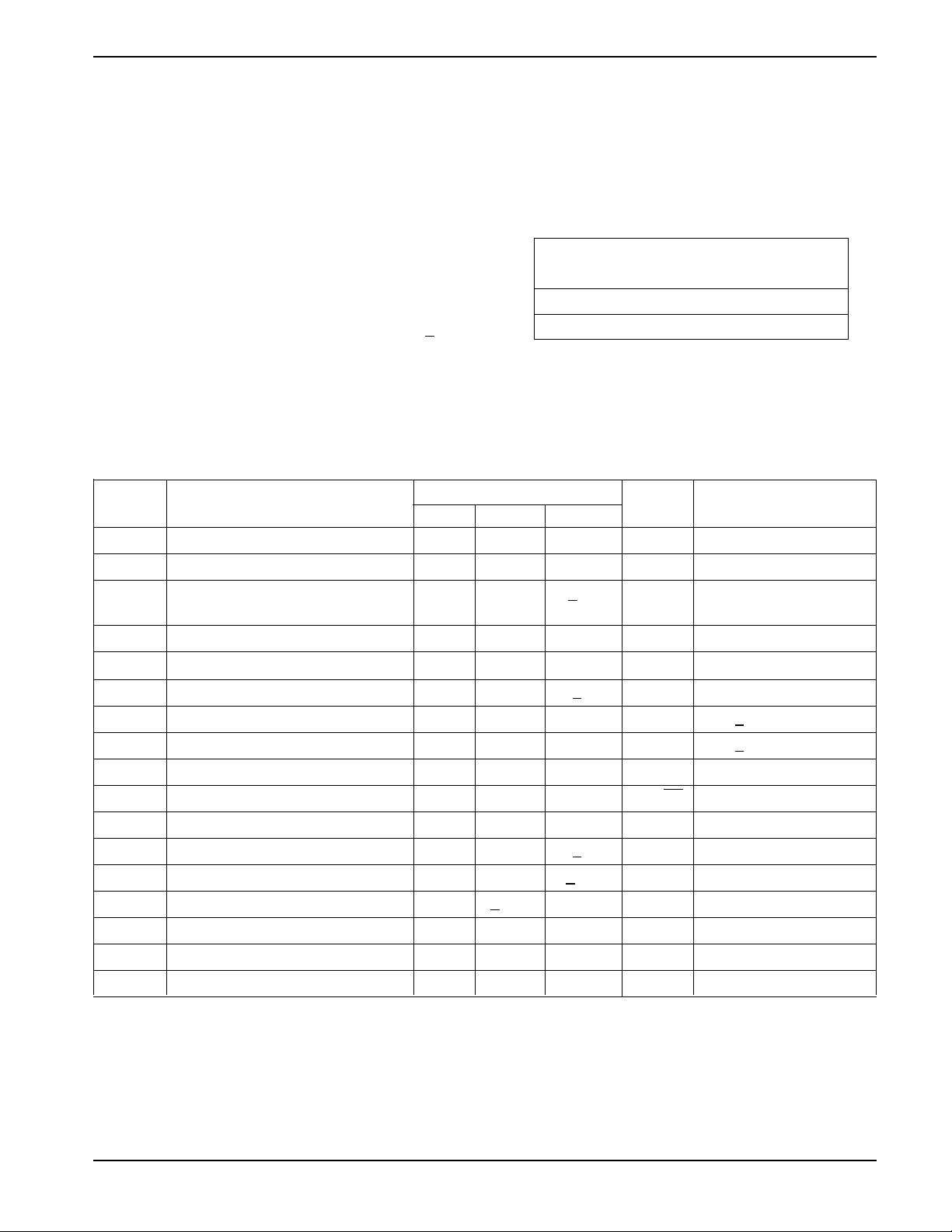
POTENTIOMETER CHARACTERISTICS
(Over recommended operating conditions unless otherwise stated.)
Limits
Symbol Parameter Min. Typ. Max. Units Test Conditions
R
R
Potentiometer Resistance (100KΩ) 100 kΩ
POT
POT
Potentiometer Resistance (50KΩ) 50 kΩ
Potentiometer Resistance +20 %
Tolerance
R
Matching 1 %
POT
Power Rating 50 mW 25°C, each pot
V
I
W
R
W
R
W
TERM
V
N
Voltage on any RH or RL Pin V
Wiper Current +3 mA
Wiper Resistance 200 300 Ω IW = +3mA @ VCC = 3V
Wiper Resistance 100 150 Ω IW = +3mA @ VCC = 5V
SS
V
CC
VV
SS
= 0V
Noise nV/√Hz (1)
Resolution 0.4 %
(3)
(2)
POT
+1 LSB
+0.2 LSB
+300 ppm/˚C (1)
TC
RPOT
TC
RATIO
CH/CL/C
Absolute Linearity
Relative Linearity
Temperature Coefficient of R
Ratiometric Temp. Coefficient 20 ppm/˚C (1)
Potentiometer Capacitances 10/10/25 pF (1)
W
fc Frequency Response 0.4 MHz R
(4)
R
w(n)(actual)-R(n)(expected)
(4)
R
w(n+1)
POT
-[R
w(n)+LSB
= 50KΩ
(1)
(5)
(5)
]
Note:
(1) This parameter is tested initially and after a design or process change that affects the parameter.
(2) Absolute linearity is utilitzed to determine actual wiper voltage versus expected voltage as determined by wiper position when used
as a potentiometer.
(3) Relative linearity is utilized to determine the actual change in voltage between two successive tap positions when used as a
potentiometer. It is a measure of the error in step size.
(4) LSB = R
(5) n = 0, 1, 2, ..., 255
/ 255 or (RH - RL) / 255, single pot
TOT
3
Document No. 2000, Rev. F
Page 4
CAT5259
D.C. OPERATING CHARACTERISTICS
VCC = +2.5V to +6.0V, unless otherwise specified.
Symbol Parameter Min Max Units Test Conditions
I
CC1
Power Supply Current 1 mA f
= 400 KHz, SDA = Open
SCL
VCC = 6 V, Inputs = GND
I
CC2
Power Supply Current 5 mA f
= 400 KHz, SDA Open
SCK
Non-volatile WRITE VCC = 6 V, Input = GND
I
SB
I
LI
I
LO
V
IL
V
IH
V
OL1
Standby Current (VCC = 5.0V) 5 µAVIN = GND or VCC, SDA = Open
Input Leakage Current 10 µAV
Output Leakage Current 10 µAV
= GND to V
IN
= GND to V
OUT
Input Low Voltage -1 VCC x 0.3 V
Input High Voltage VCC x 0.7 V
+ 1.0 V
CC
Output Low Voltage (VCC = 3.0V) 0.4 V IOL = 3 mA
CAPACITANCE
TA = 25˚C, f = 1.0 MHz, VCC = 5V
Symbol Test Max. Units Conditions
(1)
C
C
Input/Output Capacitance (SDA) 8 pF V
I/O
(1)
Input Capacitance (A0, A1, A2, A3, SCL, WP)6 pF VIN = 0V
IN
I/O
= 0V
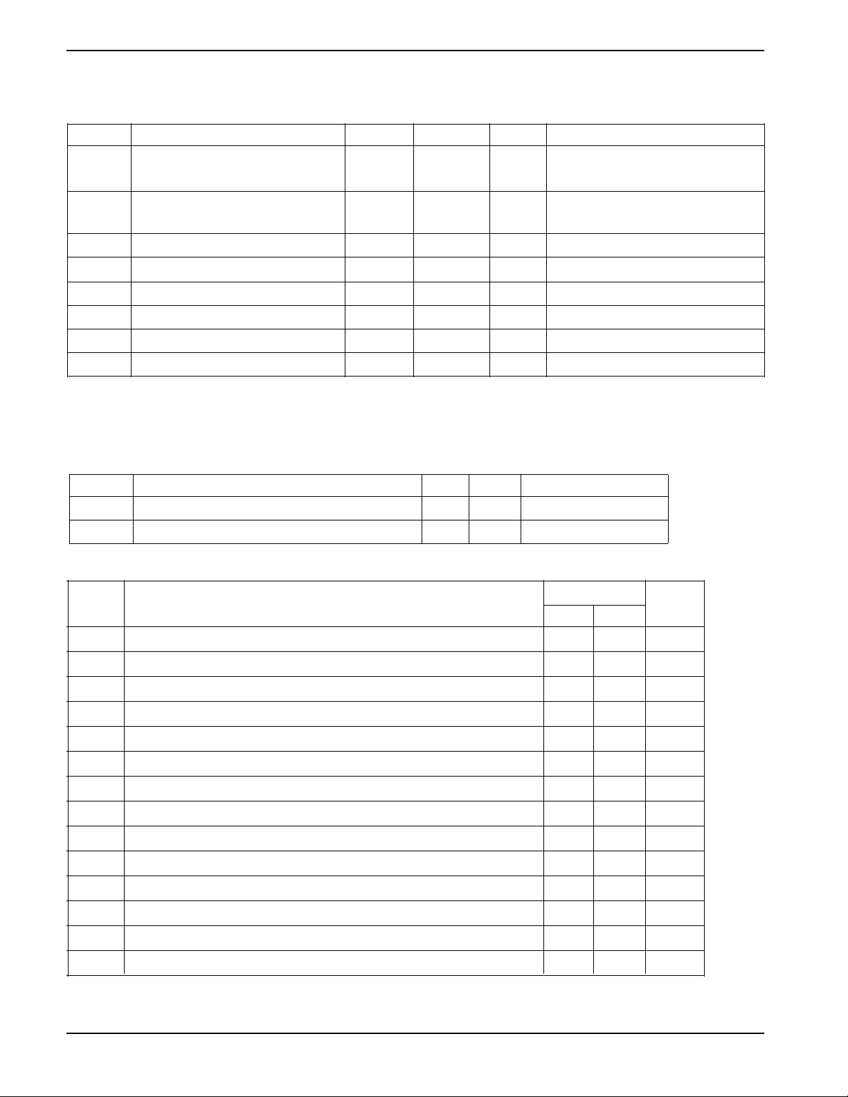
A.C. CHARACTERISTICS
2.5V-6.0V
Symbol Parameter Min. Max. Units
f
SCL
T
(1)
I
Clock Frequency 400 kHz
Noise Suppression Time Constant at SCL, SDA Inputs 200 ns
CC
CC
t
AA
(1)
t
BUF
t
HD:STA
t
LOW
t
HIGH
t
SU:STA
t
HD:DAT
t
SU:DAT
(1)
t
R
(1)
t
F
t
SU:STO
t
DH
Note:
(1) This parameter is tested initially and after a design or process change that affects the parameter.
Document No. 2000, Rev. F
SLC Low to SDA Data Out and ACK Out 1 µs
Time the bus must be free before a new transmission can start 1.2 µs
Start Condition Hold Time 0.6 µs
Clock Low Period 1.2 µs
Clock High Period 0.6 µs
Start Condition SetupTime (for a Repeated Start Condition) 0.6 µs
Data in Hold Time 0 ns
Data in Setup Time 50 ns
SDA and SCL Rise Time 0.3 µs
SDA and SCL Fall Time 300 ns
Stop Condition Setup Time 0.6 µs
Data Out Hold Time 100 ns
4
Page 5
CAT5259
POWER UP TIMING
(1)(2)
Symbol Parameter Max Units
t
PUR
t
PUW
Note:
(1) This parameter is tested initially and after a design or process change that affects the parameter.
(2) t
PUR
and t
Power-up to Read Operation 1 ms
Power-up to Write Operation 1 ms
are delays required from the time VCC is stable until the specified operation can be initiated.
PUW
XDCP TIMING
Symbol Parameter Min Max Units
t
WRPO
t
WRL
Wiper Response Time After Power Supply Stable 5 10 µs
Wiper Response Time After Instruction Issued 5 10 µs
WRITE CYCLE LIMITS
Symbol Parameter Max Units
t
WR
Write Cycle Time 5 ms
The write cycle is the time from a valid stop condition of a write sequence to the end of the internal program/erase
cycle. During the write cycle, the bus interface circuits are disabled, SDA is allowed to remain high, and the device
does not respond to its slave address.
RELIABILITY CHARACTERISTICS
Symbol Parameter Min Max Units Reference Test Method
(1)
N
END
(1)
T
DR
(1)
V
ZAP
(1)
I
LTH
Note:
(1) This parameter is tested initially and after a design or process change that affects the parameter.
Endurance 1,000,000 Cycles/Byte MIL-STD-883, Test Method 1033
Data Retention 100 Years MIL-STD-883, Test Method 1008
ESD Susceptibility 2000 Volts MIL-STD-883, Test Method 3015
Latch-Up 100 mA JEDEC Standard 17
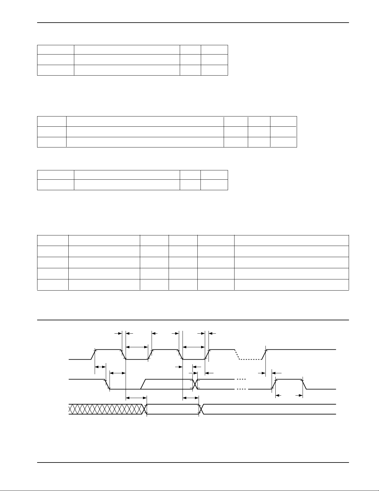
Figure 1. Bus Timing
SCL
SDA IN
SDA OUT
t
SU:STA
t
AA
t
HIGH
t
HD:DAT
t
LOW
t
F
t
LOW
t
HD:STA
t
DH
t
R
t
SU:DAT
t
SU:STO
t
BUF
5
Document No. 2000, Rev. F
Page 6

CAT5259
SERIAL BUS PROTOCOL
The following defines the features of the 2-wire bus
protocol:
(1) Data transfer may be initiated only when the bus
is not busy.
(2) During a data transfer, the data line must remain
stable whenever the clock line is high. Any
changes in the data line while the clock is high will
be interpreted as a START or STOP condition.
The device controlling the transfer is a master,
typically a processor or controller, and the device
being controlled is the slave. The master will always
initiate data transfers and provide the clock for both
transmit and receive operations. Therefore, the
CAT5259 will be considered a slave device in all
applications.
START Condition
The START Condition precedes all commands to the
device, and is defined as a HIGH to LOW transition of
SDA when SCL is HIGH. The CAT5259 monitors the
SDA and SCL lines and will not respond until this
condition is met.
STOP Condition
A LOW to HIGH transition of SDA when SCL is HIGH
determines the STOP condition. All operations must end
with a STOP condition.
DEVICE ADDRESSING
The bus Master begins a transmission by sending a
START condition. The Master then sends the address of
the particular slave device it is requesting. The four most
significant bits of the 8-bit slave address are fixed as
0101 for the CAT5259 (see Figure 5). The next four
significant bits (A3, A2, A1, A0) are the device address
bits and define which device the Master is accessing. Up
to sixteen devices may be individually addressed by the
system. Typically, +5V and ground are hard-wired to
these pins to establish the device's address.
After the Master sends a START condition and the slave
address byte, the CAT5259 monitors the bus and
responds with an acknowledge (on the SDA line) when
its address matches the transmitted slave address.
Acknowledge
After a successful data transfer, each receiving device is
required to generate an acknowledge. The
Acknowledging device pulls down the SDA line during
the ninth clock cycle, signaling that it received the 8 bits
of data.
The CAT5259 responds with an acknowledge after
receiving a START condition and its slave address. If the
device has been selected along with a write operation,
it responds with an acknowledge after receiving each
8-bit byte.
When the CAT5259 is in a READ mode it transmits 8 bits
of data, releases the SDA line, and monitors the line for
an acknowledge. Once it receives this acknowledge, the
CAT5259 will continue to transmit data. If no
acknowledge is sent by the Master, the device terminates
data transmission and waits for a STOP condition.
WRITE OPERATIONS
In the Write mode, the Master device sends the START
condition and the slave address information to the Slave
device. After the Slave generates an acknowledge, the
Master sends the instruction byte that defines the
requested operation of CAT5259. The instruction byte
consist of a four-bit opcode followed by two register
selection bits and two pot selection bits. After receiving
another acknowledge from the Slave, the Master device
transmits the data to be written into the selected register.
The CAT5259 acknowledges once more and the Master
generates the STOP condition, at which time if a nonvolatile data register is being selected, the device begins
an internal programming cycle to non-volatile memory.
While this internal cycle is in progress, the device will not
respond to any request from the Master device.
Acknowledge Polling
The disabling of the inputs can be used to take advantage
of the typical write cycle time. Once the stop condition is
issued to indicate the end of the host's write operation,
the CAT5259 initiates the internal write cycle. ACK
polling can be initiated immediately. This involves issuing
the start condition followed by the slave address. If the
CAT5259 is still busy with the write operation, no ACK
will be returned. If the CAT5259 has completed the write
operation, an ACK will be returned and the host can then
proceed with the next instruction operation.
WRITE PROTECTION
The Write Protection feature allows the user to protect
against inadvertent programming of the non-volatile
data registers. If the WP pin is tied to LOW, the data
registers are protected and become read only. Similarly,
the WP pin is going low after start will interrupt nonvolatile write to data registers, while WP pin going low
after an internal write cycle has started will have no effect
on any write operation. The CAT5259 will accept both
slave addresses and instructions, but the data registers
are protected from programming by the device’s failure
to send an acknowledge after data is received.
Document No. 2000, Rev. F
6
Page 7
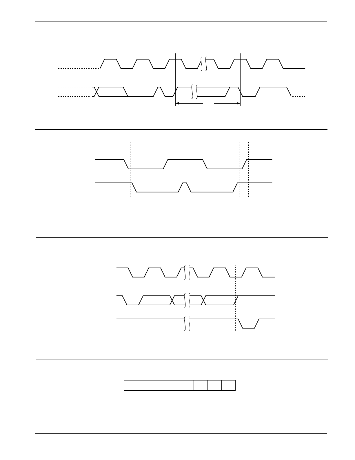
Figure 2. Write Cycle Timing
SCL
CAT5259
SDA
BYTE n
Figure 3. Start/Stop Condition
SDA
SCL
START CONDITION
Figure 4. Acknowledge Condition
ACK8TH BIT
t
WR
STOP
CONDITION
START
CONDITION
STOP CONDITION
ADDRESS
SCL FROM
MASTER
DATA OUTPUT
FROM TRANSMITTER
DATA OUTPUT
FROM RECEIVER
START
1
Figure 5. Slave Address Bits
CAT5259
* A0, A1, A2 and A3 correspond to pin A0, A1, A2 and A3 of the device.
** A0, A1, A2 and A3 must compare to its corresponding hard wired input pins.
0 1 0 1 A3A2A1A0
7
89
ACKNOWLEDGE
Document No. 2000, Rev. F
Page 8
CAT5259
INSTRUCTION AND REGISTER
DESCRIPTION
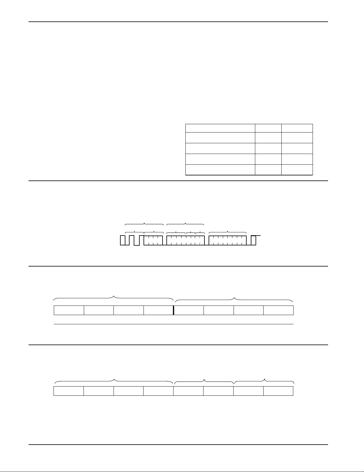
SLAVE ADDRESS BYTE
The first byte sent to the CAT5259 from the master/
processor is called the Slave/DPP Address Byte. The
most significant four bits of the slave address are a
device type identifier. These bits for the CAT5259 are
fixed at 0101[B] (refer to Table 1).
The next four bits, A3 - A0, are the internal slave address
and must match the physical device address which is
defined by the state of the A3 - A0 input pins for the
CAT5259 to successfully continue the command
sequence. Only the device which slave address matches
the incoming device address sent by the master executes
the instruction. The A3 - A0 inputs can be actively driven
by CMOS input signals or tied to V
Figure 6. Write Timing
or VSS.
CC
INSTRUCTION BYTE
The next byte sent to the CAT5259 contains the instruction
and register pointer information. The four most significant
bits used provide the instruction opcode I3 - I0. The R1
and R0 bits point to one of the four data registers of each
associated potentiometer. The least two significant bits
point to one of four Wiper Control Registers. The format
is shown in Table 2.
Data Register Selection
Data Register Selected R1 R0
DR0 0 0
DR1 0 1
DR2 1 0
DR3 1 1
S
T
BUS ACTIVITY :
MASTER
SDA LINE
A
R
T
Table 1. Identification Byte Format
Device Type
Identifier
ID3 ID2 ID1 ID0 A3 A2 A1 A0
0101
(MSB) (LSB)
Table 2. Instruction Byte Format
Instruction
Opcode
SLAVE/DPP
ADDRESS
Fixed Variable op code
S
INSTRUCTION
BYTE
A
C
K
Register
Pot1 WCR
Address
Address
Data Register
Selection
DR1 WCRDATA
A
C
K
Slave Address
S
T
O
P
P
A
C
5020 FHD F08
K
WCR/Pot Selection
I3 I2 I1 I0 R1 R0 P1 P0
(MSB) (LSB)
Document No. 2000, Rev. F
8
Page 9

CAT5259
WIPER CONTROL AND DATA REGISTERS
Wiper Control Register (WCR)
The CAT5259 contains four 8-bit Wiper Control Registers,
one for each potentiometer. The Wiper Control Register
output is decoded to select one of 256 switches along its
resistor array. The contents of the WCR can be altered
in four ways: it may be written by the host via Write Wiper
Control Register instruction; it may be written by
transferring the contents of one of four associated Data
Registers via the XFR Data Register instruction, it can be
modified one step at a time by the Increment/decrement
instruction (see Instruction section for more details).
Finally, it is loaded with the content of its data register
zero (DR0) upon power-up.
The Wiper Control Register is a volatile register that
loses its contents when the CAT5259 is powered-down.
Although the register is automatically loaded with the
value in DR0 upon power-up, this may be different from
the value present at power-down.
Data Registers (DR)
Each potentiometer has four 8-bit non-volatile Data
Registers. These can be read or written directly by the
host. Data can also be transferred between any of the
four Data Registers and the associated Wiper Control
Register. Any data changes in one of the Data Registers
is a non-volatile operation and will take a maximum of
10ms.
If the application does not require storage of multiple
settings for the potentiometer, the Data Registers can be
used as standard memory locations for system
parameters or user preference data.
INSTRUCTIONS
Four of the nine instructions are three bytes in length.
These instructions are:
—Read Wiper Control Register - read the current
wiper position of the selected potentiometer in the WCR
—Write Wiper Control Register - change current
wiper position in the WCR of the selected potentiometer
—Read Data Register - read the contents of the
selected Data Register
—Write Data Register - write a new value to the
selected Data Register
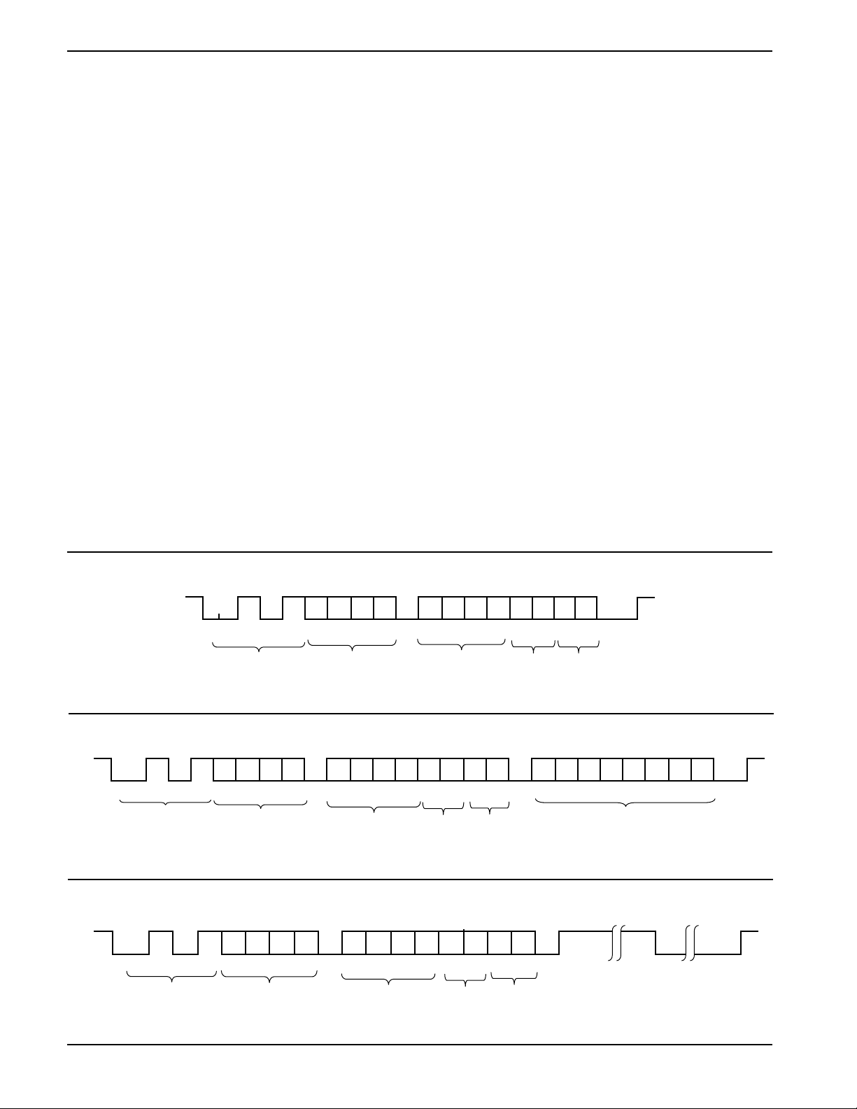
The basic sequence of the three byte instructions is
illustrated in Figure 8. These three-byte instructions
Table 3. Instruction Set
Instruction Set
P1
WCR0/
P0
Operation
Register pointed to by P1-P0
Register pointed to by P1-P0
pointed to by P1-P0 and R1-R0
pointed to by P1-P0 and R1-R0
pointed to by P1-P0 and R1-R0 to its
associated Wiper Control Register
Register pointed to by P1-P0 to the Data
Register pointed to by R1-R0
pointed to by R1-R0 of all four pots to their
respective Wiper Control Registers
Registers to their respective data Registers
pointed to by R1-R0 of all four pots
Latch pointed to by P1-P0
Instruction
Read Wiper Control
Register
Write Wiper Control Register 101000 1/0 1/0Write new value to the Wiper Control
Read Data Register 10111/01/01/0 1/0Read the contents of the Data Register
Write Data Register 11001/01/01/0 1/0Write new value to the Data Register
XFR Data Register to Wiper
Control Register
XFR Wiper Control Register
to Data Register
Gang XFR Data
to Wiper Control Registers
Gang XFR Wiper Control
Registers to Data Register
Increment/Decrement Wiper
Control Register
Note: 1/0 = data is one or zero
Registers
I3 I2 I1 I0 R1 R0
100100 1/0 1/0Read the contents of the Wiper Control
11011/01/01/0 1/0Transfer the contents of the Data Register
11101/01/01/0 1/0Transfer the contents of the Wiper Control
00011/01/0 0 0 Transfer the contents of the Data Registers
10001/01/0 0 0 Transfer the contents of both Wiper Control
001000 1/0 1/0Enable Increment/decrement of the Control
WCR1/
9
Document No. 2000, Rev. F
Page 10
CAT5259
exchange data between the WCR and one of the Data
Registers. The WCR controls the position of the wiper.
The response of the wiper to this action will be delayed
by tWR. A transfer from the WCR (current wiper position),
to a Data Register is a write to non-volatile memory and
takes a minimum of tWR to complete. The transfer can
occur between one of the four potentiometers and one
of its associated registers; or the transfer can occur
between all potentiometers and one associated register.
Four instructions require a two-byte sequence to
complete, as illustrated in Figure 7. These instructions
transfer data between the host/processor and the
CAT5259; either between the host and one of the data
registers or directly between the host and the Wiper
Control Register. These instructions are:
—XFR Data Register to Wiper Control Register
This transfers the contents of one specified Data
Register to the associated Wiper Control Register.
—XFR Wiper Control Register to Data Register
This transfers the contents of the specified Wiper
Control Register to the specified associated
Data Register.
—Gang XFR Data Register to Wiper
Control Register
This transfers the contents of all specified Data
Registers to the associated Wiper Control
Registers.
—Gang XFR Wiper Counter Register to
Data Register
This transfers the contents of all Wiper Control
Registers to the specified associated Data
Registers.
INCREMENT/DECREMENT COMMAND
The final command is Increment/Decrement (Figure 9
and 10). The Increment/Decrement command is different from the other commands. Once the command is
issued and the CAT5259 has responded with an acknowledge, the master can clock the selected wiper up
and/or down in one segment steps; thereby providing a
fine tuning capability to the host. For each SCL clock
pulse (t
) while SDA is HIGH, the selected wiper will
HIGH
move one resistor segment towards the RH terminal.
Similarly, for each SCL clock pulse while SDA is LOW,
the selected wiper will move one resistor segment
towards the RL terminal.
Figure 7. Two-Byte Instruction Sequence
SDA
0101
ID3 ID2 ID1 ID0
S
T
A
R
T
Device ID
A3
A1
A2 A0
Internal
Address
A
C
K
Figure 8. Three-Byte Instruction Sequence
SDA
0101
S
ID3 ID2
T
A
Device ID
R
T
ID1
ID0
A3
A2 A1 A0
Internal
Address
A
C
K
I3
Instruction
Opcode
I1
I2
I0
Figure 9. Increment/Decrement Instruction Sequence
See Instructions format for more detail.
I2 I1
I3
Instruction
Opcode
R1 R0
Data
Register
Address
I0
P1 P0 A
Pot/WCR
Address
R1 R0 P1
Register
Address
C
K
P0
A
C
K
Pot/WCR
Address
D7 D6 D5 D4 D3 D2 D1 D0
WCR[7:0]
Data Register D[7:0]
or
S
T
O
P
S
A
T
C
O
K
P
SDA
Document No. 2000, Rev. F
0101
ID3 ID2 ID1ID0
S
T
A
Device ID
R
T
A3
A2 A1 A0
Internal
Address
A
C
K
I3 I2
Instruction
Opcode
I1
I0
R1
R0 P1 P0
Data
Register
Address
Pot/WCR
Address
A
I
C
K
I
N
N
C
C
1
2
D
I
E
N
C
C
1
n
S
D
T
E
O
C
P
n
10
Page 11
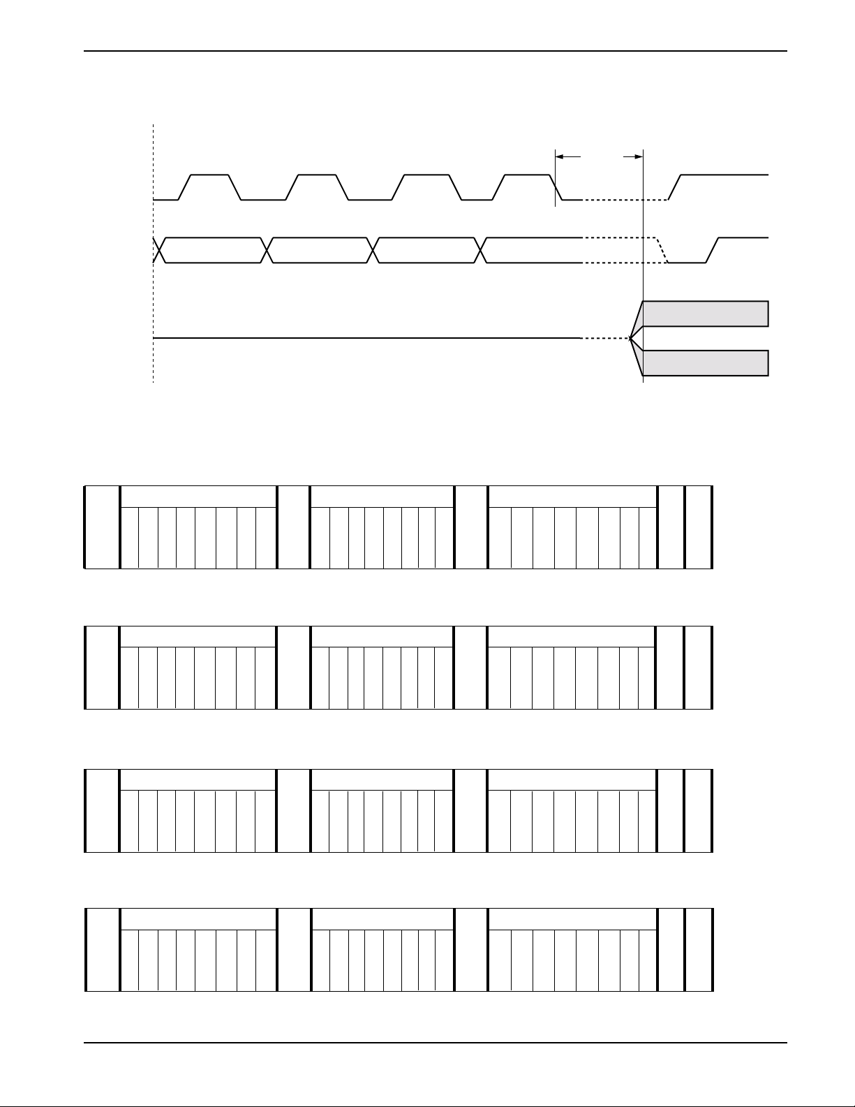
Figure 10. Increment/Decrement Timing Limits
INC/DEC
Command
Issued
SCL
SDA
t
WRL
CAT5259
R
W
Voltage Out
INSTRUCTION FORMAT
Read Wiper Control Register (WCR)
S
DEVICE ADDRESSES INSTRUCTION DATA
T
0 101AAAA 100100PP 76 5 4 3 210
A
R
3210 10
A
C
K
T
Write Wiper Control Register (WCR)
S
DEVICE ADDRESS INSTRUCTION DATA
T
0101AAAA 101000PP 76 5 43 210
A
R
3210 10
A
C
K
T
A
C
K
A
C
K
S
A
T
C
O
K
P
S
A
T
C
O
K
P
Read Data Register (DR)
S
DEVICE ADDRESS INSTRUCTION DATA
T
0 101A AAA 10 11RRPP 76 5 4 3 210
A
R
3210 1010
A
C
K
A
C
K
T
Write Data Register (DR)
S
DEVICE ADDRESS INSTRUCTION DATA
T
0101AAAA 1100RRPP 76 5 43 210
A
R
3210 1010
A
C
K
A
C
K
T
11
S
A
T
C
O
K
P
S
A
T
C
O
K
P
Document No. 2000, Rev. F
Page 12
CAT5259
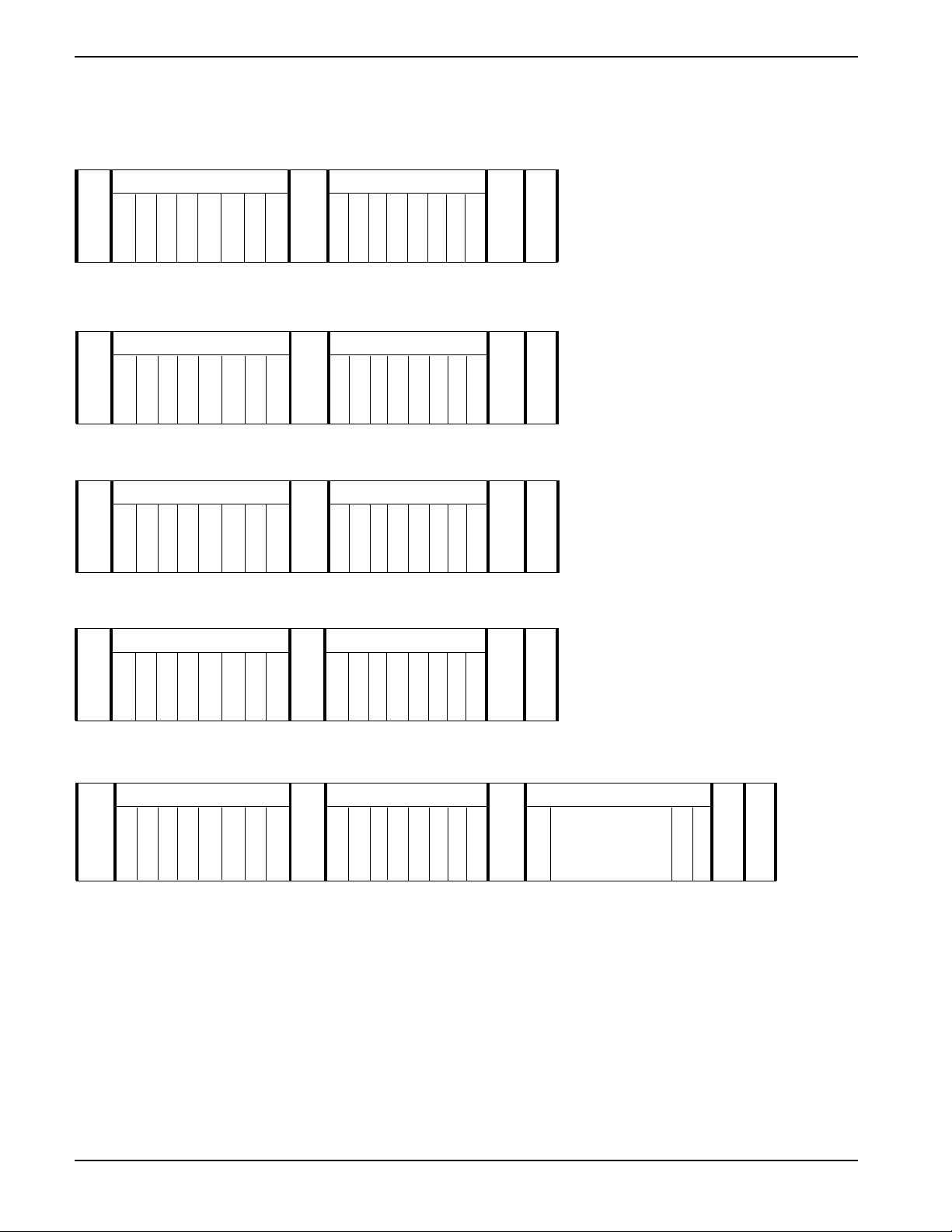
INSTRUCTION FORMAT (continued)
Gang Transfer Data Register (DR) to Wiper Control Register (WCR)
S
S
DEVICE ADDRESS INSTRUCTION
T
0101AAAA 0001RR00
A
R
3210 10
A
C
K
T
Gang Transfer Wiper Control Register (WCR) to Data Register (DR)
S
DEVICE ADDRESS INSTRUCTION
T
0 101AAAA 1000RR00
A
R
3210 10
A
C
K
T
Transfer Wiper Control Register (WCR) to Data Register (DR)
S
DEVICE ADDRESS INSTRUCTION
T
0101AAAA 1110RRPP
A
R
3210 1010
A
C
K
T
A
T
C
O
K
P
S
A
T
C
O
K
P
S
A
T
C
O
K
P
Transfer Data Register (DR) to Wiper Control Register (WCR)
S
S
DEVICE ADDRESS INSTRUCTION
T
0101AAAA 1101RRPP
A
R
3210 1010
A
C
K
A
T
C
O
K
P
T
Increment (I)/Decrement (D) Wiper Control Register (WCR)
S
DEVICE ADDRESS INSTRUCTION DATA
T
0101AAAA 001000PP II II
A
R
3210 10 // //
A
C
K
T
Notes:
(1) Any write or transfer to the Non-volatile Data Registers is followed by a high voltage cycle after a STOP has been issued.
A
C
K
• • •
DD DD
A
C
K
S
T
O
P
Document No. 2000, Rev. F
12
Page 13
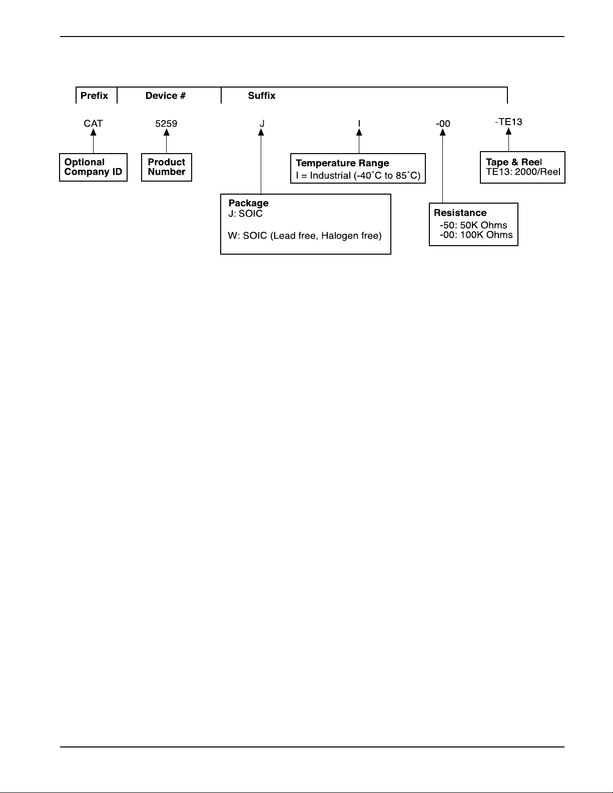
ORDERING INFORMATION
U: TSSOP
Y: TSSOP (Lead free, Halogen free)
Notes:
(1) The device used in the above example is a CAT5259JI00-TE13 (SOIC, Industrial Temperature, 100K Ohm, Tape & Reel)
CAT5259
13
Document No. 2000, Rev. F
Page 14
CAT5259
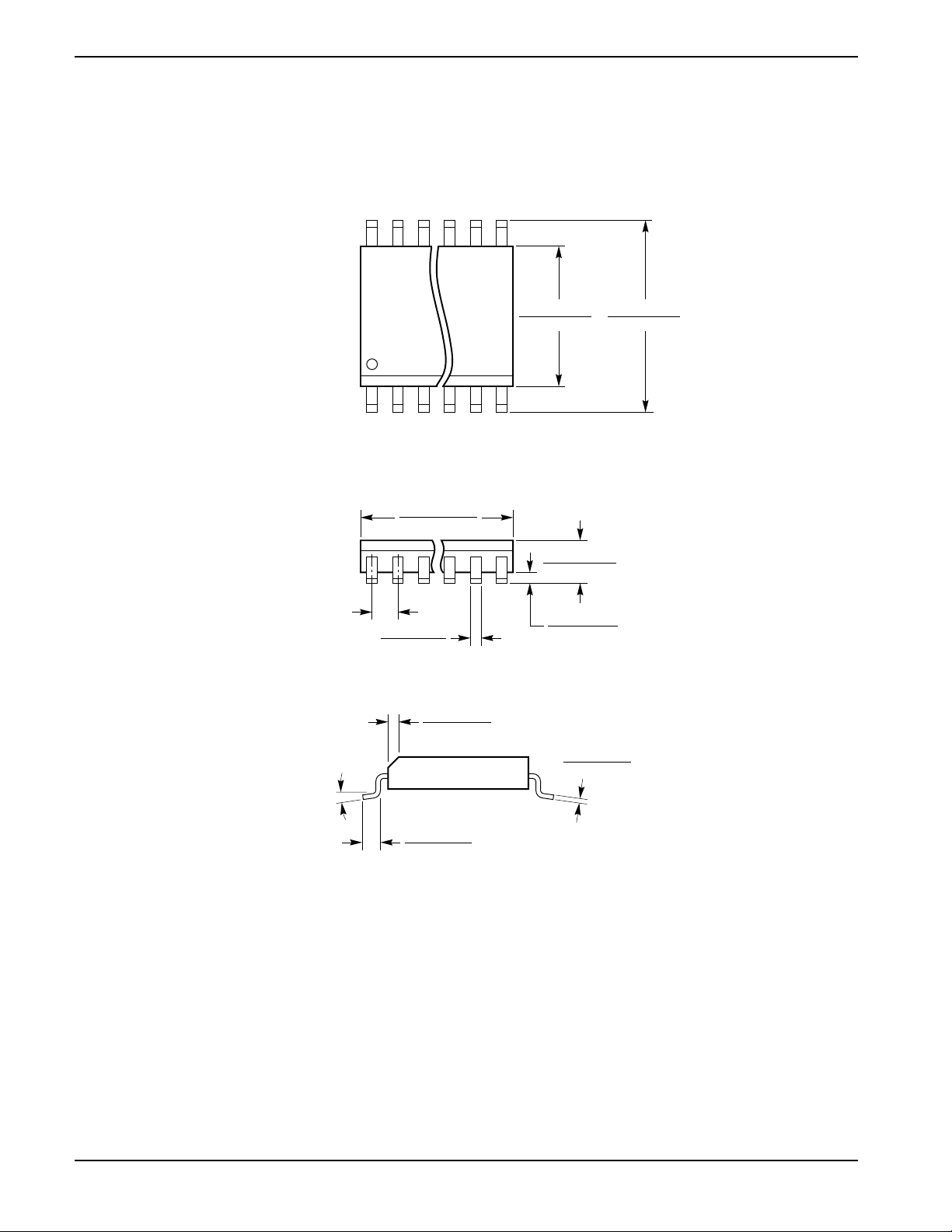
PACKAGING INFORMATION
24-LEAD 300 MIL WIDE SOIC (J, W)
0.050 (1.27) BSC
0.5985 (15.20)
0.6141 (15.60)
0.013 (0.33)
0.020 (0.51)
0.010 (0.25)
0.029 (0.75)
0.2914 (7.40)
0.2992 (7.60)
X 45
0.394 (10.00)
0.419 (10.65)
0.0926 (2.35)
0.1043 (2.65)
0.0040 (0.10)
0.0118 (0.30)
0.0091 (0.23)
0.0125 (0.32)
0 —8
0.016 (0.40)
0.050 (1.27)
Note: Package information shown in Inches (mm).
Document No. 2000, Rev. F
14
Page 15
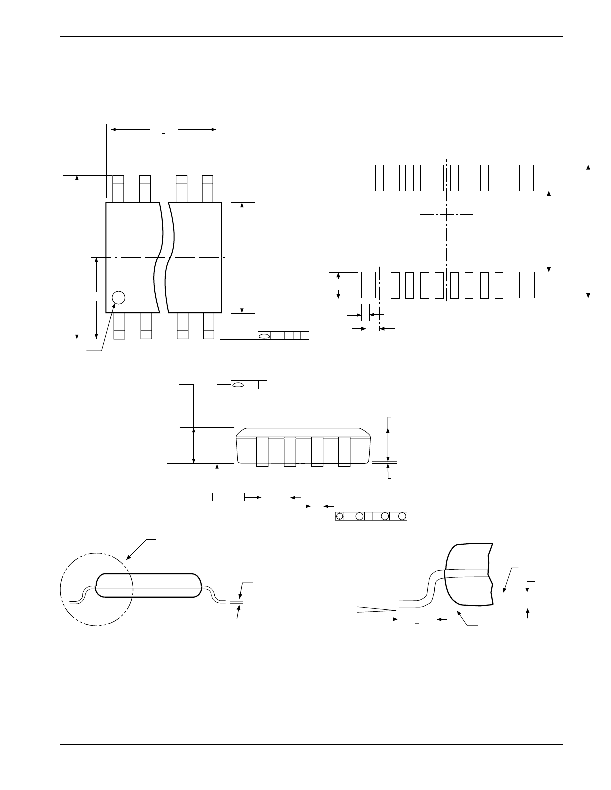
PACKAGING INFORMATION
24-LEAD TSSOP (U, Y)
7.8 + 0.1
-A-
CAT5259
7.72 TYP
6.4
PIN #1 INDENT.
3.2
1.1 MAX TYP
-C-
4.4 + 0.1
0.65 TYP
-B-
ALL LEAD TIPS
0.1 C
ALL LEAD TIPS
0.2 C B A
4.16 TYP
(1.78 TYP)
0.42 TYP
0.65 TYP
LAND PATTERN RECOMMENDATION
(0.9)
0.10 + 0.05 TYP
0.19 - 0.30 TYP
0.3 M A B S C S
SEE DETAIL A
Note: Package information shown in mm.
0.09 - 0.20 TYP
15
0o- 8
GAGE PLANE
0.25
o
0.6+0.1
SEATING PLANE
DETAIL A
Document No. 2000, Rev. F
Page 16
REVISION HISTORY
Date Rev. Reason
11/12/2003 C Eliminated BGA package in all areas
Eliminated Commercial temperature range
Added "Green" package marking
3/18/04 D Added TSSOP package in all areas
5/7/2004 E Updated Functional Diagram
Updated Pin Descriptions
Updated notes in Absolute Max Ratings
Updated Potentiometer Characteristics table
Updated DC Characteristics table
Added XDCP table
Updated Write Protection text
Changed Figure 3 drawing to Start/Stop Condition from
Start/Stop Timing
Changed Figure 4 title from Acknowledge Timing to Acknowledge Condition
Corrected Instruction Format for Gang Transfer Data Register (DR)
to Wiper Control Register (WCR)
9/21/2004 F Updated DC Operating Characteristics table
Copyrights, Trademarks and Patents
Trademarks and registered trademarks of Catalyst Semiconductor include each of the following:
DPP ™ AE2 ™
Catalyst Semiconductor has been issued U.S. and foreign patents and has patent applications pending that protect its products. For a complete list of patents
issued to Catalyst Semiconductor contact the Company’s corporate office at 408.542.1000.
CATALYST SEMICONDUCTOR MAKES NO WARRANTY, REPRESENTATION OR GUARANTEE, EXPRESS OR IMPLIED, REGARDING THE SUITABILITY OF ITS
PRODUCTS FOR ANY PARTICULAR PURPOSE, NOR THAT THE USE OF ITS PRODUCTS WILL NOT INFRINGE ITS INTELLECTUAL PROPERTY RIGHTS OR THE
RIGHTS OF THIRD PARTIES WITH RESPECT TO ANY PARTICULAR USE OR APPLICATION AND SPECIFICALLY DISCLAIMS ANY AND ALL LIABILITY ARISING
OUT OF ANY SUCH USE OR APPLICATION, INCLUDING BUT NOT LIMITED TO, CONSEQUENTIAL OR INCIDENTAL DAMAGES.
Catalyst Semiconductor products are not designed, intended, or authorized for use as components in systems intended for surgical implant into the body, or
other applications intended to support or sustain life, or for any other application in which the failure of the Catalyst Semiconductor product could create a
situation where personal injury or death may occur.
Catalyst Semiconductor reserves the right to make changes to or discontinue any product or service described herein without notice. Products with data sheets
labeled "Advance Information" or "Preliminary" and other products described herein may not be in production or offered for sale.
Catalyst Semiconductor advises customers to obtain the current version of the relevant product information before placing orders. Circuit diagrams illustrate
typical semiconductor applications and may not be complete.
Catalyst Semiconductor, Inc.
Corporate Headquarters
1250 Borregas Avenue
Sunnyvale, CA 94089
Phone: 408.542.1000
Fax: 408.542.1200
www.catalyst-semiconductor.com
Publication #: 2000
Revison: F
Issue date: 9/21/04
 Loading...