

Page 1
OPERATING MANUAL:
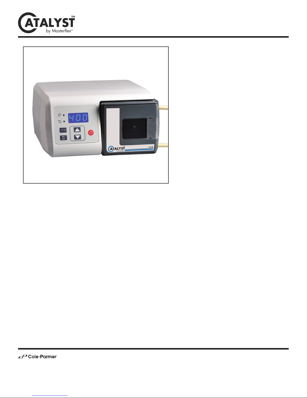
FH100 PRECISION
VARIABLE-SPEED
PERISTALTIC PUMP
SYSTEM
Model 77722-00
Model Nos.
77722-00
77722-02
A-1299-7292
Edition 01
(US & Canada only) Toll Free 1-800-MASTERFLEX • 1-800-637-3739
(Outside US & Canada) 1-847-549-7600 • 1-847-381-7050
E-mail: [email protected]
www.masterflex.com • www.coleparmer.com
Page 2

Cole-Parmer
Preface
FH100 Precision Variable-Speed Peristaltic Pump System Operating Manual ii
Preface
© 2014 Cole-Parmer Instrument Company LLC. All rights reserved.
NORPRENE, PHARMED and TYGON – Reg TM Saint-Gobain Performance Plastics Corp.
Trademarks bearing the ®symbol in this publication are registered in the U.S. and in other countries.
A-1299-7292
01 19714 2014-10-29 First Edition SR
REV ECR/ECN DATE DESCRIPTION By
Page 3
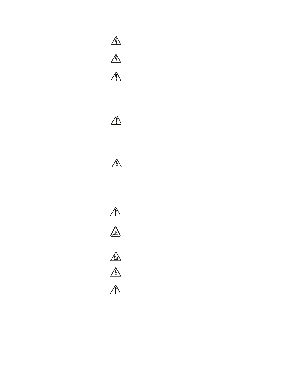
DANGER: Remove power from the pump before any
cleaning operation is started.
WARNING: Remove power from the pump before attempting
any maintenance.
WARNINGS: Tubing breakage may result in fluid being sprayed
from pump. Use appropriate measures to protect operator and
equipment.
Turn Pump System off before removing or installing tubing.
Fingers or loose clothing could get caught in drive mechanism.
CAUTIONS: When changing flow direction, allow the pump to
come to a complete stop before starting again. Failure to do so
could cause permanent damage to the motor.
Replace the fuse only with one of the same type and rating.
The fuse rating and type are stated on the rear panel.
CAUTION: To avoid electrical shock, the power cord
protective grounding conductor must be connected to ground.
Not for operation in wet locations as defined by EN61010-1.
If the product is not used in a manner specified in the
instructions, the protection provided by the equipment may
be impaired.
CAUTION: Risk of Danger. Consult Operator’s manual for nature
of hazard and corrective actions.
CAUTION: Risk of crushing. Keep fingers away from rotor
while pump is in operation. Stop pump before loading or
unloading tubing.
CAUTION: Hot Surface. Do not touch.
CAUTION: Risk of electric shock. Consult Operator’s manual
for nature of hazard and corrective actions.
This product is not designed for, nor intended for use in patient
connected applications; including, but not limited to, medical
and dental use, and accordingly has not been
submitted for FDA approval.
This product is not designed for, nor intended for use in
hazardous duty areas as defined by ATEX or the NEC (National
Electrical Code); including, but not limited to use with
flammable liquids. Consult the factory for products suitable
for these types of applications.
Cole-Parmer FH100 Precision Variable-Speed Peristaltic Pump System Operating Manual iii
Preface
Safety Precautions
SAFETY
PRECAUTIONS
Explanation of
Symbols
WARNING:
Product Use
Limitation
Page 4

1. Read instructions before operating the unit.
2. Observe safety precautions at all times, especially when pumping
dangerous liquids. Always have the clear plastic cover properly
mounted on the Pump Head and, in general, protect the pump area
from accidental spillage of liquid.
3. If the pump runs unusually noisily or if bunching of the tubing in the
pump can be observed, make sure the tubing is clamped down tightly
and/or replace it with a new piece of tubing.
4. The FH100 Pump System must be well-grounded at all times.
5. The FH100 Pump System is equipped with a current-limiting circuit
that will slow the motor down if any of the following conditions exist:
a. Tubing that is too hard is loaded in the pump.
b. Incorrect tubing size or wall thickness is loaded in the pump.
c. Tubing is improperly loaded into the Pump Head.
6. The unit is fused and grounded to protect the operator in the event of
short circuits that could be caused by liquid entering the case.
CAUTION: Replace the fuse only with one of the same type
and rating. The fuse rating and type are stated on the
rear panel.
7. The Pump System should not be used in outdoor or hazardous
locations.
Safety
Cole-Parmeriv FH100 Precision Variable-Speed Peristaltic Pump System Operating Manual
Preface
Page 5

FH100 Precision Variable-Speed Peristaltic Pump System Operating Manual vCole-Parmer
Table of Contents
Page
INTRODUCTION . . . . . . . . . . . . . . . . . . . . . . . . . . . . . . . . . . . . . . . . . . . . . .1-1
General Description . . . . . . . . . . . . . . . . . . . . . . . . . . . . . . . . . . . . . . . . . . . . .1-1
Controls, Indicators and Connectors . . . . . . . . . . . . . . . . . . . . . . . . . . . . . . . .1-2
INSTALLATION AND SETUP . . . . . . . . . . . . . . . . . . . . . . . . . . . . . . . . . . .2-1
Tubing Size Selection . . . . . . . . . . . . . . . . . . . . . . . . . . . . . . . . . . . . . . . . . . .2-1
OPERATION . . . . . . . . . . . . . . . . . . . . . . . . . . . . . . . . . . . . . . . . . . . . . . . . .3-1
Inserting Tubing . . . . . . . . . . . . . . . . . . . . . . . . . . . . . . . . . . . . . . . . . . . . . . . .3-1
Tubing Inspection and Replacement . . . . . . . . . . . . . . . . . . . . . . . . . . . . . . .3-2
Pump Controls . . . . . . . . . . . . . . . . . . . . . . . . . . . . . . . . . . . . . . . . . . . . . . . .3-2
External Operation . . . . . . . . . . . . . . . . . . . . . . . . . . . . . . . . . . . . . . . . . . . . . .3-3
External Inputs . . . . . . . . . . . . . . . . . . . . . . . . . . . . . . . . . . . . . . . . . . . . . . . . .3-4
MAINTENANCE . . . . . . . . . . . . . . . . . . . . . . . . . . . . . . . . . . . . . . . . . . . . . .4-1
Cleaning . . . . . . . . . . . . . . . . . . . . . . . . . . . . . . . . . . . . . . . . . . . . . . . . . . . . . .4-1
TROUBLESHOOTING . . . . . . . . . . . . . . . . . . . . . . . . . . . . . . . . . . . . . . . . . .5-1
Troubleshooting Chart . . . . . . . . . . . . . . . . . . . . . . . . . . . . . . . . . . . . . . . . . . .5-1
REPLACEMENT PARTS and ACCESSORIES . . . . . . . . . . . . . . . . . . . . . .6-1
Replacement Parts . . . . . . . . . . . . . . . . . . . . . . . . . . . . . . . . . . . . . . . . . . . . .6-1
Accessories . . . . . . . . . . . . . . . . . . . . . . . . . . . . . . . . . . . . . . . . . . . . . . . . . . .6-1
SPECIFICATIONS . . . . . . . . . . . . . . . . . . . . . . . . . . . . . . . . . . . . . . . . . . . . .7-1
WARRANTY, PRODUCT RETURN and TECHNICAL ASSISTANCE . . . .8-1
Warranty . . . . . . . . . . . . . . . . . . . . . . . . . . . . . . . . . . . . . . . . . . . . . . . . . . . . .8-1
Product Return . . . . . . . . . . . . . . . . . . . . . . . . . . . . . . . . . . . . . . . . . . . . . . . . .8-2
Technical Assistance . . . . . . . . . . . . . . . . . . . . . . . . . . . . . . . . . . . . . . . . . . . .8-2
Section 1
Section 2
Section 3
Section 6
Section 8
Section 7
Section 4
Section 5
Page 6

Page 7

Figures
Page
Controls, Indicators and Connectors . . . . . . . . . . . . . . . . . . . . . . . . . . . . . . . .1-2
Tube Loading Upper Retainer . . . . . . . . . . . . . . . . . . . . . . . . . . . . . . . . . . . . .3-1
Tube Loading Lower Retainer . . . . . . . . . . . . . . . . . . . . . . . . . . . . . . . . . . . . .3-2
DB9 Pin Configuration with Wiring Scheme . . . . . . . . . . . . . . . . . . . . . . . . .3-3
FH100 Precision Variable-Speed Peristaltic Pump System Operating Manual viiCole-Parmer
Figures
Page 8

Page 9

FH100 Precision Variable-Speed Peristaltic Pump System Operating Manual 1-1Cole-Parmer
Section 1 Introduction
The FH100 Precision Variable-Speed Peristaltic Pump System provides
continuous pumping of fluids while power is supplied.
These Pump Systems are ETL and CE certified. The pump speed range
for both models is 4-400 rpm.
General Description
Page 10
1-2 FH100 Precision Variable-Speed Peristaltic Pump System Operating Manual Cole-Parmer
Section 1
Introduction
Controls, Indicators
and Connectors
Rear View
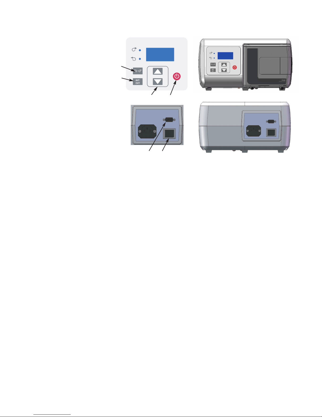
Figure 1-1. Controls, Indicators and Connectors
A
B
E
C
D
A. POWER (ON/OFF) SWITCH: Turns the unit ON or OFF.
B. SPEED KEYS: Sets the speed of the pump. The higher the number,
the faster the speed of the pump. When setting the displayed values,
units change first, then tens, etc. at an increasing rate.
C. FLOW DIRECTION KEY: Sets the direction of the rotation of the
pump Clockwise/Counterclockwise. An LED annunciator shows the
active direction. The motor is brought to a controlled stop before
reversing direction.
D. INTERNAL/EXTERNAL KEY: This key changes the mode of
operation for the drive. Internal (Local) operation throught the front
panel keypad is designated by “INT” while external (Remote)
operation is designated by “EXT”. In INT mode, START/STOP,
FLOW DIRECTION, and SPEED keys on the front panel
determine operating state. Pressing and releasing this key will toggle
between the two operating states.
E. START/STOP KEY: When depressed, this key toggles the motor on
and off when in INT mode. This key will not normally start the drive
if in EXT mode. If pressed while running in EXT mode (stop
desired), the button will always stop the drive and a toggle of the
EXT Start/Stop is required to restart the drive.
F. EXTERNAL/REMOTE CONNECTOR: Used to connect wiring for
remote control operation using a DB9 connector.
F
Front View
Page 11

FH100 Precision Variable-Speed Peristaltic Pump System Operating Manual 2-1Cole-Parmer
Section 2 Installation and Setup
Unpack the pump and retain all packing material until proper product
operation has been verified. Select the tubing according to the flow
desired, while considering chemical compatibility and tubing life.
Flow rate is determined by the size of the tubing in the Pump Head.
When tubing links are used, best performance will be achieved when input
and output tubing connected to the link are the same ID as the link.
77722-00 Pump Systems accept tubing ID sizes of 0.8 mm to 8.0 mm
(1/32 in to 5/16 in ) by 1.6 mm (1/16 in) wall.
77722-02 Pump Systems accept tubing ID sizes of 4.8 mm to 9.5 mm
(3/16 in to 3/8 in) by 2.4 mm (3/32 in) wall.
For best results, select a tubing size with a mid-range at the desired flow
rate to be pumped.
Tubing Size Selection
Page 12

Page 13
FH100 Precision Variable-Speed Peristaltic Pump System Operating Manual 3-1Cole-Parmer
Inserting Tubing
Section 3 Operation
WARNINGS: Tubing breakage may result in fluid being sprayed
from pump. Use appropriate measures to protect operator and
equipment.
Turn Pump System off before removing or installing tubing.
Fingers or loose clothing could be caught in the pump
mechanism.
CAUTION: To avoid electrical shock, the power cord protective
grounding conductor must be connected to ground. Not for
operation in wet locations as defined by EN61010-1.
If the product is not used in a manner specified in the
instructions, the protection provided by the equipment
may be impaired.
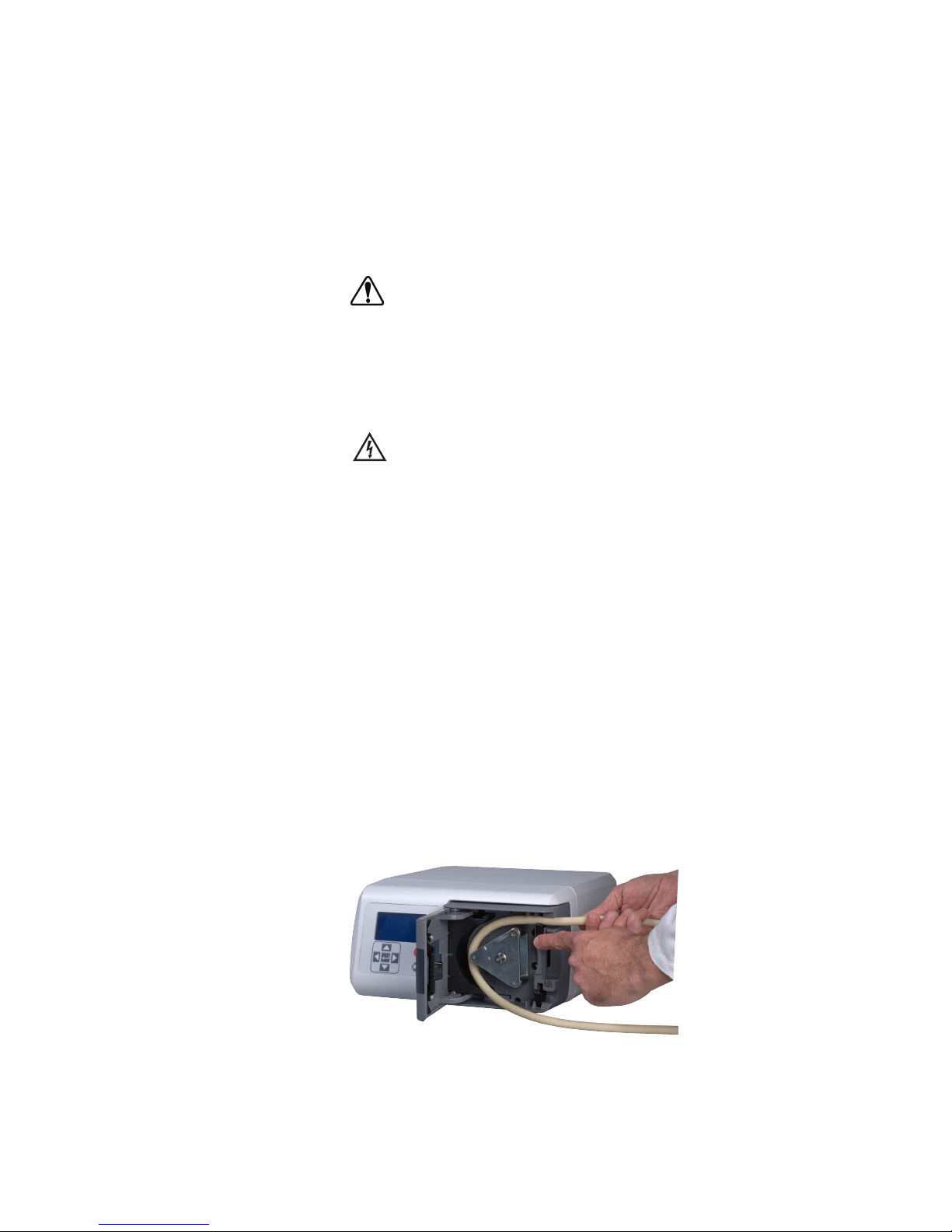
The Pump Head has two tubing retainers, which hold tubing in place.
The occlusion bed retracts when you open the pump door and moves
forward when the door is closed.
To load tubing into the Pump Head do the following:
1. Make sure that the power switch is turned OFF.
2. Open the Pump Head door using the side latch.
3. Install any tube fittings, inserts or clamps before loading the tubing.
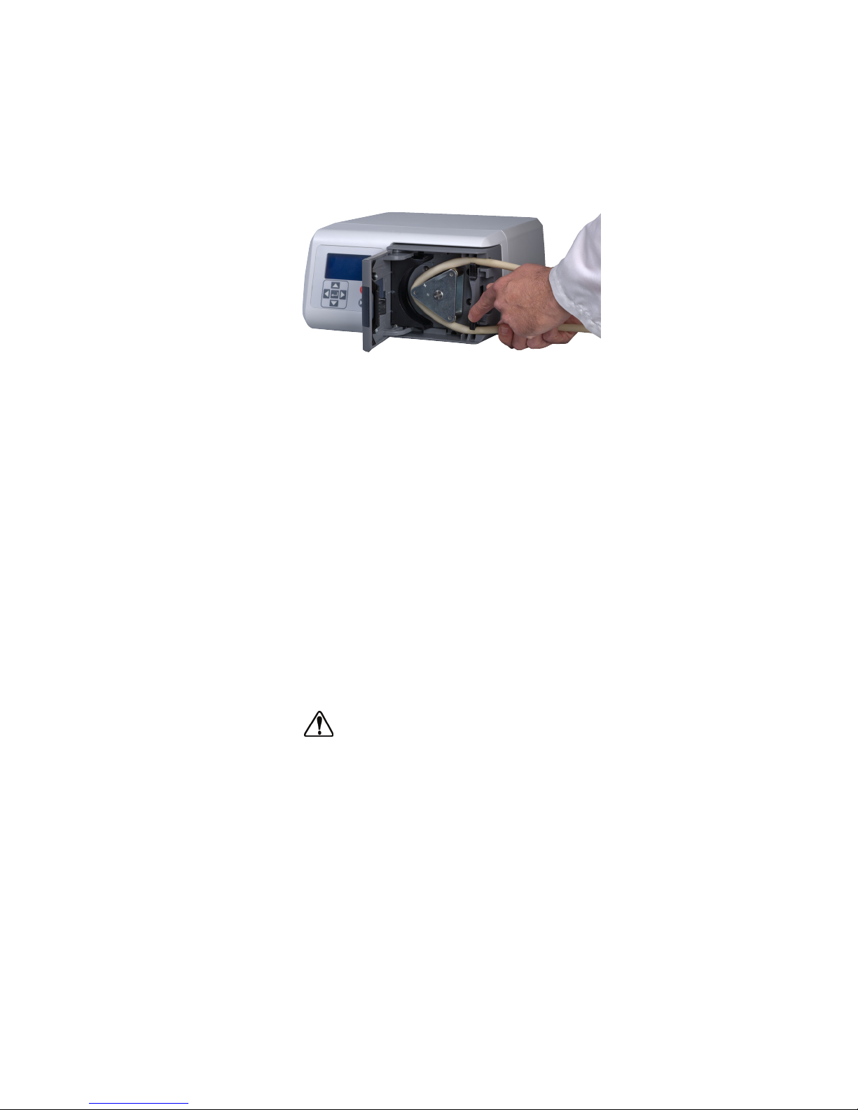
4. Open the top tubing retainer by using just one finger to open the
retainer, install tubing and release the retainer.
Figure 3-1. Tube Loading Upper Retainer
Page 14
3-2 FH100 Precision Variable-Speed Peristaltic Pump System Operating Manual Cole-Parmer
Section 3
Operation
5. Install the tubing around the rotor, going with the natural curve or lay
of the tubing and center the tubing on the rollers.
6. Open the lower retainer by using just one finger to open the retainer
and insert the tube and release the retainer.
Figure 3-2. Tube Loading Lower Retainer
7. The tubing should be snug against the rotor, but not tight.
8. Close the Pump Head door. Verify that the door is securely shut or the
pump will not spin.
Tubing should be inspected periodically and checked for tears, cracks, cut
marks, abrasions, inability to hold pressure, bubbles in the flow stream and
reduction or loss of flow.
Tubing life may be extended by periodically moving the worn tubing
inside the occlusion bed of the pump to the outside of the occlusion bed
to the suction side of the pump. This will avoid excessive tubing wear at
any specific point.
Always move the worn tubing to the suction side of the pump.
CAUTION: When changing flow direction, allow the pump to
come to a complete stop before starting again. Failure to do so
could cause permanent damage to the motor.
1. Make sure the speed is set to the minimum setting.
2. Turn the power switch ON. Increase the speed to start the pump
action. The higher the rpm, the faster the speed of the pump.
3. The Pump Systems are self-priming. To begin pumping, select a flow
direction with the flow direction button, insert the intake and output
tubing into a reservoir, and turn the unit ON. Prime the tubing for
at least 5 minutes. If accurate flow control is important, allow the
pump to prime for approximately 20 minutes for more stable
flow conditions.
Inserting Tubing
(continued)
Tubing Inspection and
Replacement
Pump Controls
Page 15
FH100 Precision Variable-Speed Peristaltic Pump System Operating Manual 3-3Cole-Parmer
Section 3
Operation
External Operation
Models are equipped with inputs that can be controlled by external signals
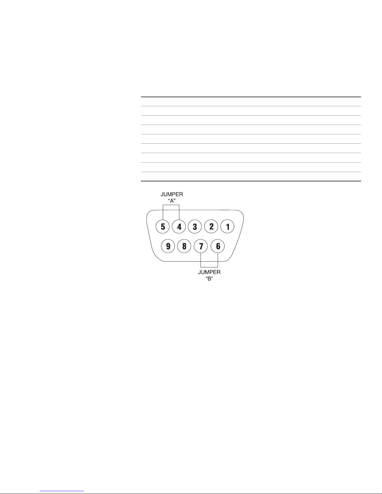
connected at the rear panel 9-pin “D” shell connector. The External inputs
permit control of the pump by remote equipment or accessories. Figure 3-3
shows the signal locations of the connector.
Pin No. Description
1 Speed Control Voltage Input (0–10V) (+) input
2 Speed Control Current Input (4–20 mA) (+) input
3 Speed Control Input Reference Common
4 Local/Remote Speed Control
5 Local/Remote Speed Control Reference
6 Start/Stop and CW/CCW Reference
7 Start/Stop (+) Control
8 CW/CCW
9 Chassis (Earth) Ground
Figure 3-3. DB9 Pin Configuration with Wiring Scheme
Page 16

3-4 FH100 Precision Variable-Speed Peristaltic Pump System Operating Manual Cole-Parmer
Section 3
Operation
External Inputs
The FRONT INT/EXT key enables external functions. Switching to INT
on the display disables the external functions, allowing the front panel
controls to operate the pump.
When the INT/EXT key is in the EXT position, starting and stopping the
pump is controlled by an external contact closure between pins 6 and 7
(Jumper B), and the pump speed is determined by an externally supplied
0–10V or 4–20 mA source. Connection must be made between pins 6 and
7 and a control voltage greater than 0V or a control current greater than 4
mA must be applied for the pump to run.
If setting the speed from the front panel is desired with external Start/Stop
contact operation, the INT/EXT key must again be in the EXT position.
In addition, Jumper A should be in place. Jumper A connects pin 4 of the
“D” shell connector (Local/Remote) to pin 5 (Local/Remote Reference).
Start/Stop will then be controlled from the rear panel (Jumper B), and the
pump speed will be controlled from the front panel. The accessory
Footswitch (part no. 07595-40) and Dispenser Wand (part no.
77722-80) are connected internally in this way.
NOTE: The signal common for the speed control voltage and current
inputs is referenced to earth ground.
The START/STOP (pin 7) input, CW/CCW (pin 8) and Local/Remote
(pin 4) are digital inputs. They are internally pulled up to +5 V with
respect to logic common (RETURNS). They can alternately be driven
with open collector logic. For increased noise immunity, use of contact
closures is recommended.
Page 17
FH100 Precision Variable-Speed Peristaltic Pump System Operating Manual 4-1Cole-Parmer
Section 4 Maintenance
WARNING: Remove power from the pump before
attempting any maintenance.
The speed control circuit has solid-state components that do not require
service. An excessive load on the system may, however, cause the fuse to
blow. An indication of an excessive load is a switch that does not light
with power applied to the pump and when the ON-OFF switch is in the
ON position. If this condition occurs, remove power from the unit and
remove the fuse from the fuse holder located on the rear of the pump.
Replace the fuse with a fuse of the same type and rating. This information
is printed on the rear of the unit.
CAUTION: Replace the fuse only with one of the same
type and rating. The fuse rating and type are stated on
the rear panel.
DANGER: Remove power from the pump before any cleaning
operation is started.
Keep the pump enclosure clean by using a mild detergent solution. Never
immerse nor use excessive fluid when cleaning the pump.
Cleaning
Page 18

Page 19

FH100 Precision Variable-Speed Peristaltic Pump System Operating Manual 5-1Cole-Parmer
Section 5 Troubleshooting
Symptom Remedy
Unit will not turn on Verify that the unit is plugged into a functioning outlet.
Verify that the power cord is firmly attached to the unit.
Verify that the fuse for the incoming voltage is not
blown (located in the slot next to the power cord).
Verify that the pump head door is securely shut.
Check the tubing. Tubing should be snug, but not tight,
against the rollers.
Verify that the mode EXT/INT is set correctly.
Error XX is displayed on the screen Err's 3 & 7, check pump for obstructions, all other Errs
return unit for repair.
Unit will turn on but display would Verify that the incoming voltage meets the required
dim and pump will not spin minimum of 90Vrms.
Unit vibrates excessively when Check that the tubing was loaded properly.
pump is running
Troubleshooting Chart
Unit will turn on
but pump will not spin
Page 20

Page 21

FH100 Precision Variable-Speed Peristaltic Pump System Operating Manual 6-1Cole-Parmer
Section 6 Replacement Parts and Accessories
Description Part Number Qty.
Rubber Foot (pkg. of 6) A-1390-0004-CR 1
Fuse (T3.15A, 250V, 5 x 20 mm) 77500-25 1
Pump Replacement (for model 77722-00) 112616-CR 1
Pump Replacement (for model 77722-02) 112617-CR 1
Ferrite, Line Cord Snap-on, (CE Required) B-3689-CR 1
Line Cord, Australia 50001-60 1
Line Cord, Denmark 50001-62 1
Line Cord, India 50001-64 1
Line Cord (115V), United States 50001-68 1
Line Cord, Israel 50001-69 1
Line Cord, Europe 50001-70 1
Line Cord, England 50001-72 1
Line Cord, Switzerland 50001-74 1
Line Cord, Italy 50001-76 1
Line Cord (230V), United States 50001-78 1
Description Part Number
Footswitch 07595-40
Dispenser Wand 77722-80
DB-9 External Control Connector 07595-45
PTFE Sinkers — keep intake tube at bottom of reservoir:
Small: 1/16 in to 1/8 in (1.6 mm to 3.2 mm) ID tubing; Large: 3/16 in to 5/16 in (4.8 mm to 8.0 mm)
Sinkers, (1 Small and 1 Large) 77310-03
Small Sinkers 1/16 in – 1/8 in (1.6 mm – 3.2 mm) 78226-81
Large Sinkers 3/16 in – 1/4 in (4.8 mm – 6.4 mm) each 78226-82
Replacement Parts
Accessories
Page 22

Page 23

Section 7 Specifications
Output:
Speed: 4 - 400 rpm
Torque: 168 in-oz (12.1 kg•cm)
Input:
Operating Voltage/Frequency: 90-260Vrms, 50/60 Hz, 1.6A @ 115Vrms,
1.9A @ 230 Vrms
External Inputs:
START/STOP, CW/CCW, Contact closure
Remote/Local Speed Control
Voltage input 0–10V DC @ 10 kohm,
Accuracy: ±0.5% Full Scale
Current input 4–20 mA @ 250 ohm,
Accuracy: ±0.5% Full Scale
Environment:
Operating Temperature: 32 to 104°F (0 to 40°C)
Storage Temperature: -13 to 149°F (-25 to 65°C)
Humidity: 10% to 90% non-condensing
Altitude: Less than 6562 ft (2000 m)
Pollution Degree: Pollution degree 2 (indoor use–lab, office)
Construction:
Dimensions (L × W × H): 12.5 in × 11 in × 6 in
(31.8 cm × 27.9 cm × 15.2 cm)
Weight: 5.67 kgs (12.5lbs)
Color: Light Grey (5% Black)
Material: Aluminum, ABS plastic and vinyl
Enclosure Rating: IP31 per IEC-60529
Compliance: UL 61010-1, CAN/CSA-C22.2 No. 61010-1
This product has been tested to the requirements of
CAN/CSA-C22.2 No. 61010-1, second edition,
including Amendment 1, or a later version of the
same standard incorporating the same level of
testing requirements.
(For CE Mark):
EN61010-1: (EU Low Voltage Directive) and
EN61326: (EU EMC Directive)
FH100 Precision Variable-Speed Peristaltic Pump System Operating Manual 7-1Cole-Parmer
Page 24

Page 25

Section 8 Warranty, Product Return and
Technical Assistance
This product is warranted against defects in material or workmanship, and
at the option of the manufacturer or distributor, any defective product will
be repaired or replaced at no charge, or the purchase price will be refunded
to the purchaser, provided that: (a) the warranty claim is made in writing
within the period of time specified on the warranty card, (b) proof of
purchase by bill of sale or receipted invoice is submitted concurrently with
the claim and shows that the product is within the applicable warranty
period, and (c) the purchaser complies with procedures for returns set
forth in the general terms and conditions contained in the manufacturer's
or distributor's most recent catalog.
This warranty shall not apply to: (a) defects or damage resulting from: (i)
misuse of the product, (ii) use of the product in other than its normal and
customary manner, (iii) accident or neglect, (iv) improper testing,
operation, maintenance, service, repair, installation, or storage, (v)
unauthorized alteration or modification, or (b) post-expiration dated
materials.
THIS WARRANTY IS THE EXCLUSIVE REMEDY OF THE
PURCHASER, AND THE MANUFACTURER AND DISTRIBUTOR
DISCLAIM ALL OTHER WARRANTIES, WHETHER EXPRESS,
IMPLIED, OR STATUTORY, INCLUDING WITHOUT
LIMITATION, WARRANTIES OF MERCHANTABILITY AND
FITNESS FOR A PARTICULAR PURPOSE. NO EMPLOYEE,
AGENT, OR REPRESENTATIVE OF THE MANUFACTURER OR
DISTRIBUTOR IS AUTHORIZED TO BIND THE
MANUFACTURER OR DISTRIBUTOR TO ANY OTHER
WARRANTY. IN NO EVENT SHALL THE MANUFACTURER OR
DISTRIBUTOR BE LIABLE FOR INCIDENTAL, INDIRECT,
SPECIAL OR CONSEQUENTIAL DAMAGES.
The warranty period for this product is one (1) year from date of purchase.
FH100 Precision Variable-Speed Peristaltic Pump System Operating Manual 8-1Cole-Parmer
Warranty
Page 26

8-2 FH100 Precision Variable-Speed Peristaltic Pump System Operating Manual Cole-Parmer
Section 8
Warranty, Product Return and
Technical Assistance
To limit charges and delays, contact the seller or Manufacturer for
authorization and shipping instructions before returning the product, either
within or outside of the warranty period. When returning the product, please
state the reason for the return. For your protection, pack the product
carefully and insure it against possible damage or loss. Any damages resulting
from improper packaging are your responsibility.
If you have any questions about the use of this product, contact the
Manufacturer or authorized seller.
Product Return
Technical Assistance
Page 27

Page 28

Printed in U.S.A.
(US & Canada only) Toll Free 1-800-MASTERFLEX • 1-800-637-3739
(Outside US & Canada) 1-847-549-7600 • 1-847-381-7050
www.masterflex.com • www.coleparmer.com
E-mail: [email protected]
*EN809 manufactured by:
Cole-Parmer Instrument Company LLC
28W092 Commercial Avenue
Barrington, IL 60010
 Loading...