

Page 1

C O N T E N T S
01 – BILL OF MATERIAL
02 – REQUIRED TOOLS
03 – BUILD PREPARATION
04 – ASSEMBLY PROCESS
05 – OPTIONAL HD CAMERA MOUNT INSTALL
06 – LIPO INSTALLATION
Page 2
SECTION 01
BILL OF MATERIAL
Page 3

QUANTITY PART DESCRIPTION
1 Top Fuselage Plate (1.5mm CF)
1 Main Frame Plate (3mm CF)
1 FPV Camera Cage Top Plate (3mm CF)
2 FPV Camera Cage, Side Plate (1.5mm CF)
1 PDB Bay Cover Plate (1.5mm CF)
1 PDB Bay Guard (Black 3D Printed ABS Plastic)
1Antenna Mount (Black 3D Printed TPU)
2 Antenna Tubes (Blue Plastic 1/8” Diameter)
1FPV Camera Adjustment Mount (Black 3D Printed ABS Plastic)
2 Standoff (Black aluminum M3 thread x 32mm long)
4 Standoff (Black aluminum M3 thread x 18mm long)
4 Standoff (Black aluminum M3 thread x 12.5mm long)
1 XT60 Passthrough Grommet (Black Rubber)
1 Velcro Lipo Strap – Catalyst Machineworks
1 FPV PRO Power Distribution Board – Catalyst Machineworks *If purchased your frame with PDB*
4 Flight Controller Hex Standoff (Black plastic M3 thread x 10mm long)
4 Flight Controller Nut (Black plastic M3 thread)
4 Flight Controller/FC Mount Screw (Black plastic M3 thread x 10mm long)
4 PDB Spacer (Black plastic M3 hole)
4 PDB Guard Inserts (Silver Aluminum M3 Hole x 4.5mm OD x 6mm long)
2 Antenna Mount Inserts (Silver Aluminum M3 Hole x 4.5mm OD x 5mm long)
2 FPV Camera Mount Adjustment Screw (Phillips head #4 x 3/8” long x stainless steel)
2 FPV Camera Mount Screws (Phillips head #2 x 3/8” long x stainless steel)
20 Washer (M3 x aluminum)
4 Socket Head Screw (M3 x 10mm long x blue 7075 aluminum)
Page 4

8 Socket Head Screw (M3 x 8mm long x blue 7075 aluminum)
4 Socket Head Screw (M3 x 16mm long x blue 7075 aluminum)
2 Button Head Screw (M3 x 6mm long x blue 7075 aluminum)
2 Socket Head Screw (M3 x 12mm long x blue 7075 aluminum)
16 Socket Head Screw (M3 x 6mm long x blue 7075 aluminum)
4Nut (M3 x blue 7075 aluminum)
2 Set Screw (M3 x 10mm long x steel)
1 GoPro Camera Mount (Black 3D Printed TPU) *Optional - Not Included. Sold separately*
1 Xiaomi Yi Camera Mount (Black 3D Printed TPU) *Optional - Not Included. Sold separately*
1 Mobius / Runcam Camera Mount (Black 3D Printed TPU) *Optional - Not Included. Sold separately*
Page 5
SECTION 02
REQUIRED TOOLS
Page 6

QUANTITY TOOL DESCRIPTION
1 File (not required but suggested)
1 Sandpaper (not required but suggested)
1 2mm allen driver or allen wrench
1 2.5mm allen driver or allen wrench
1 5.5mm socket driver
1 Small phillips head screw driver
1 Needle Nose Pliers
1 Open face wrenches (5.5mm) and (6.5mm), or adjustable
1 Loctite
3 Adult beverage of choice or apple juice if you are under 21
Page 7
SECTION 03
BUILD PREPARATION
Page 8
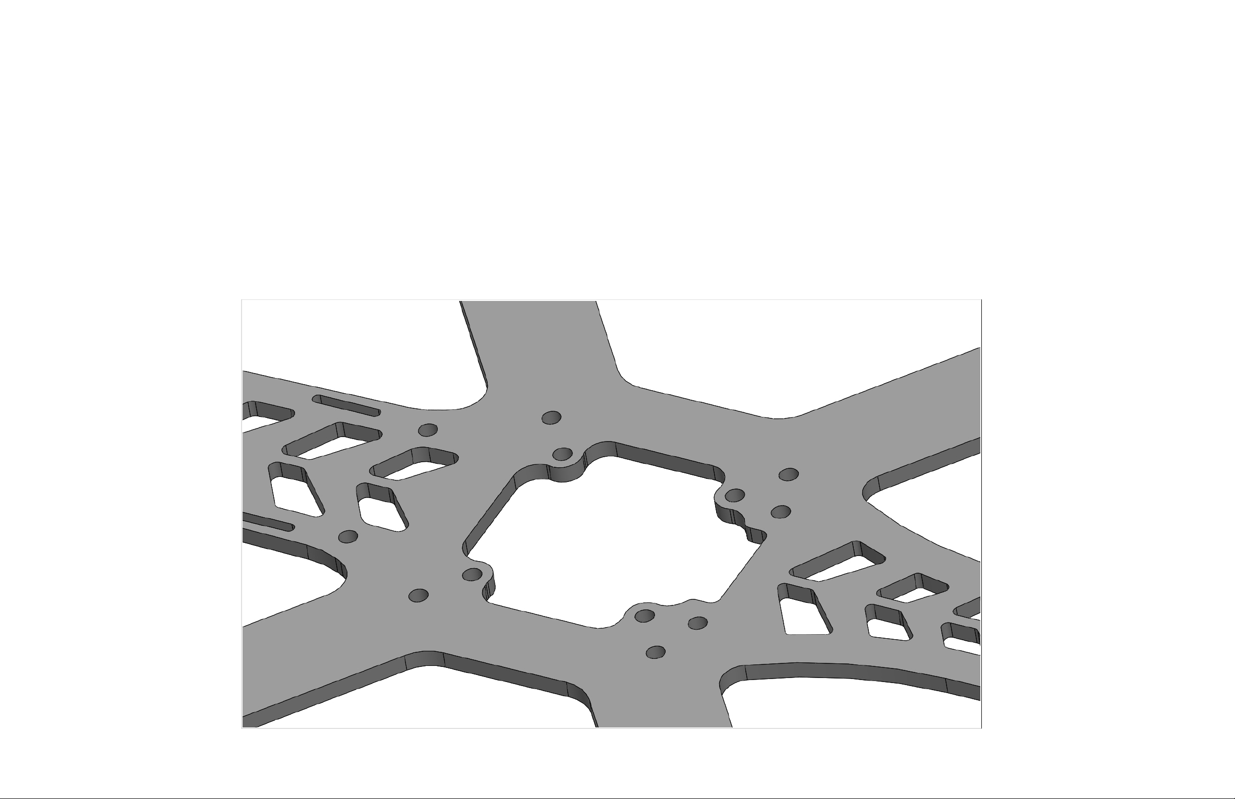
Build preparation involves rounding off the corners of the large interior 'PDB hole' in the main frame plate. This is not absolutely necessary to fly your
Speed Addict 210-R or 180-R, but it is highly recommended and standard practice among top builders and racers. Catalyst Machineworks carbon
fiber plate parts are cut by state of the art CNC machines. Cutting the raw material could leave a sharp edge on parts and it is possible this sharp
edge could rub against wiring insulation, resulting in wiring shorts against the frame. Rounding the edges is quite easy to do, but does take some time
as the process must be done with caution. Take your time and do it right, scratches on the flat surface will show. Keep that carbon fiber looking
good!
To round the edge of the carbon fiber simply take a file or sanding block and hold the sanding edge at a 45º angle to the sharp edge. Work the
sanding surface along the edge of the part until the sharp edge is gone. You want a smooth, rounded edge along the entire interior perimeter of
the hole. Below is a picture of the PDB hole.
Page 9
SECTION 4
ASSEMBLY PROCESS
Page 10

Note: This assembly manual applies to both the Speed Addict 210-R and 180-R. The 180-R has shorter arms and a
slightly shorter fuselage. Assembly steps will be identical.
STEP 1
Parts Required:
1 X Main Frame Plate (3mm CF)
8 X Socket Head Screw (M3 x 8mm long x blue 7075 aluminum)
2 X Standoff (Black aluminum M3 thread x 32mm long)
4 X Standoff (Black aluminum M3 thread x 18mm long)
2 X Standoff (Black aluminum M3 thread x 12.5mm long)
Assembly Process:
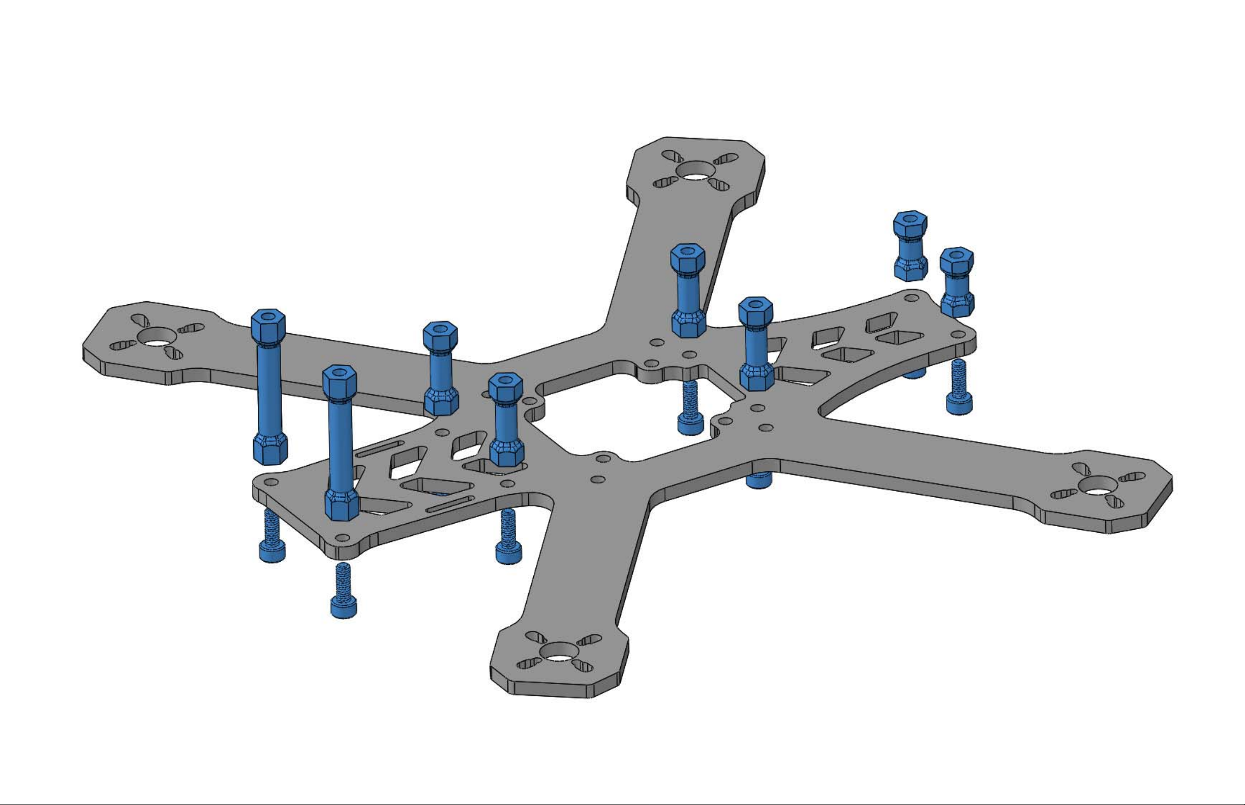
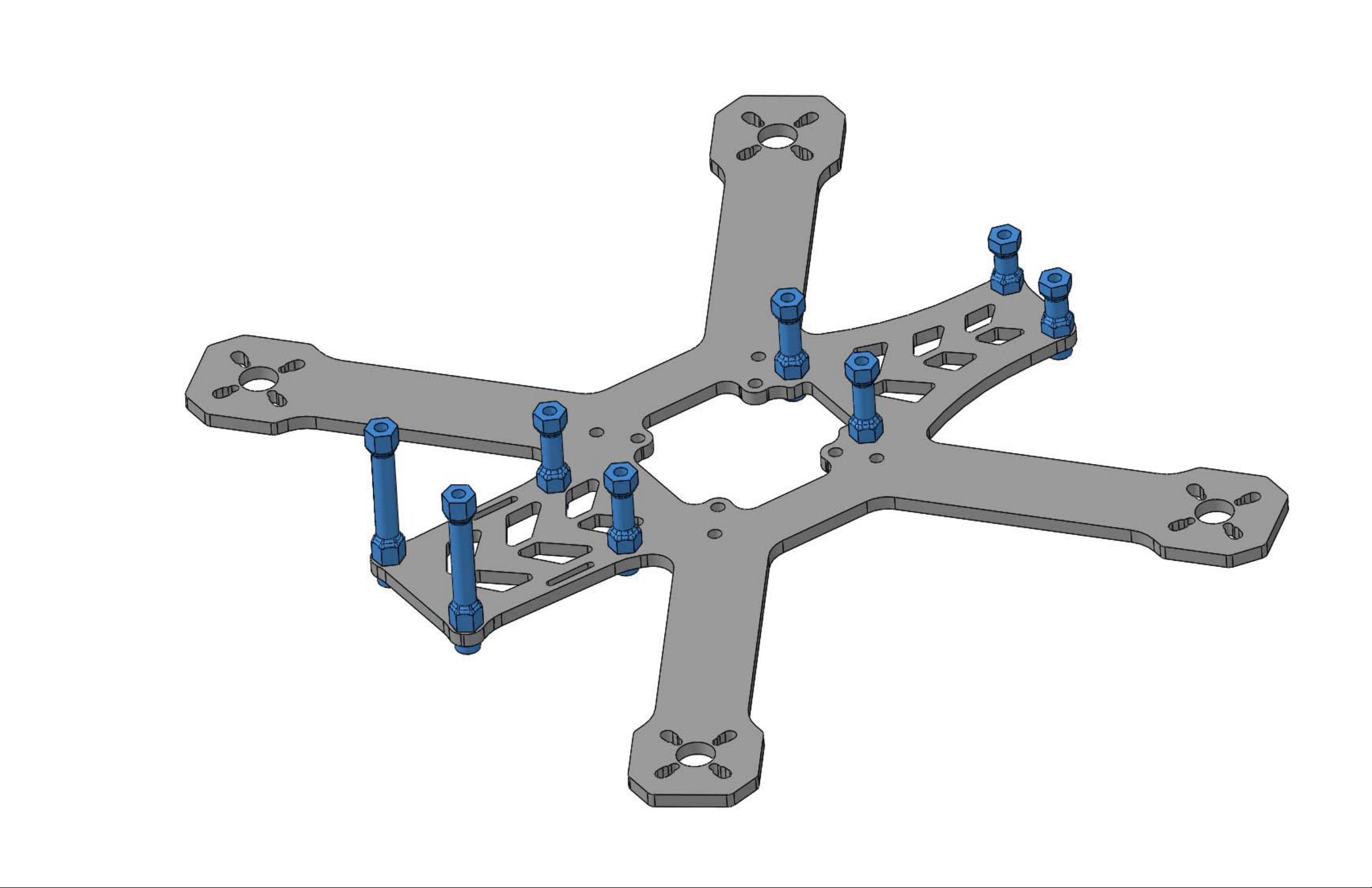
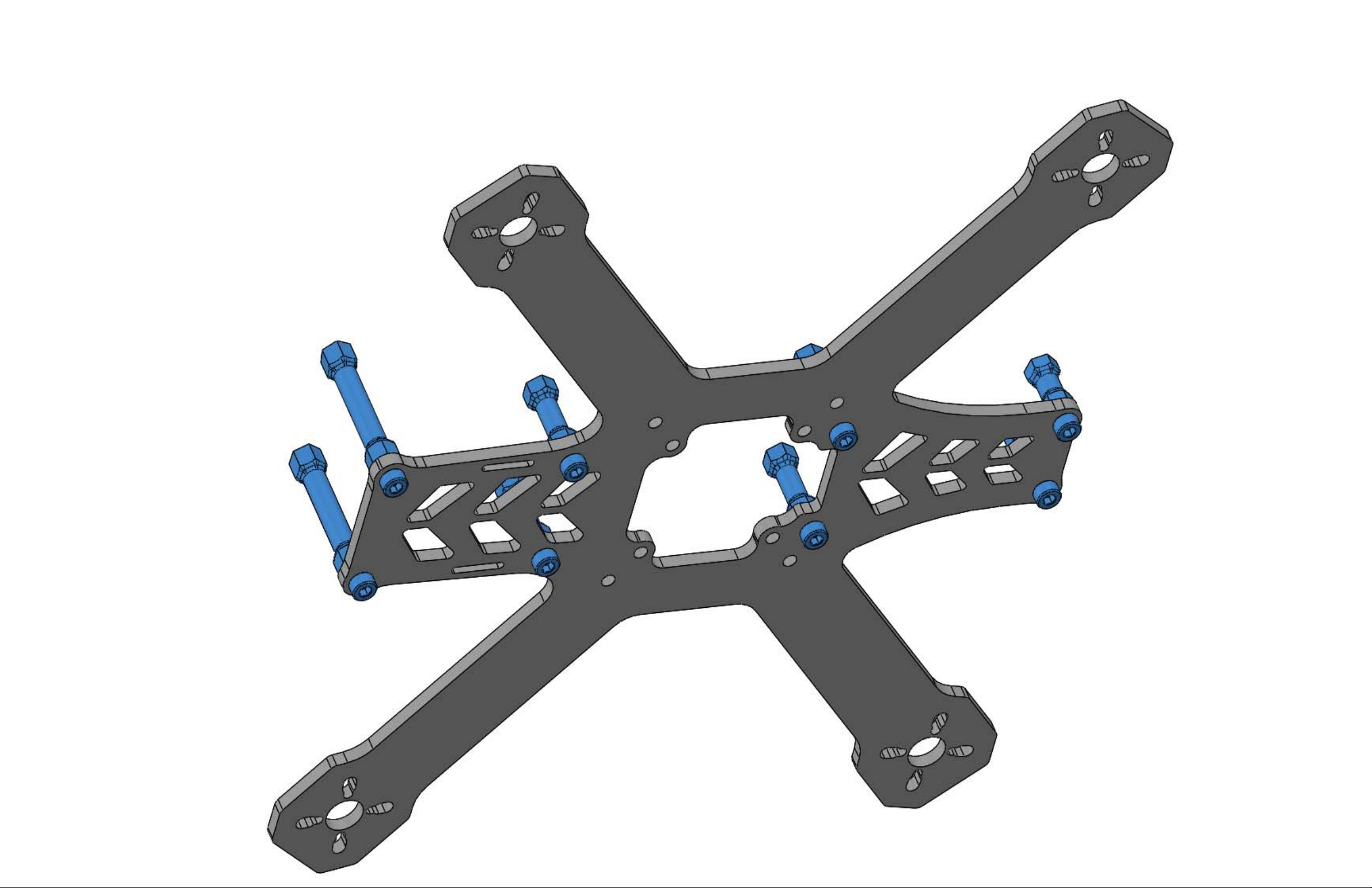
Join the standoffs to the Main Frame Plate as shown below. Use one screw per standoff.
Page 11
Page 12
Page 13
Page 14

STEP 2
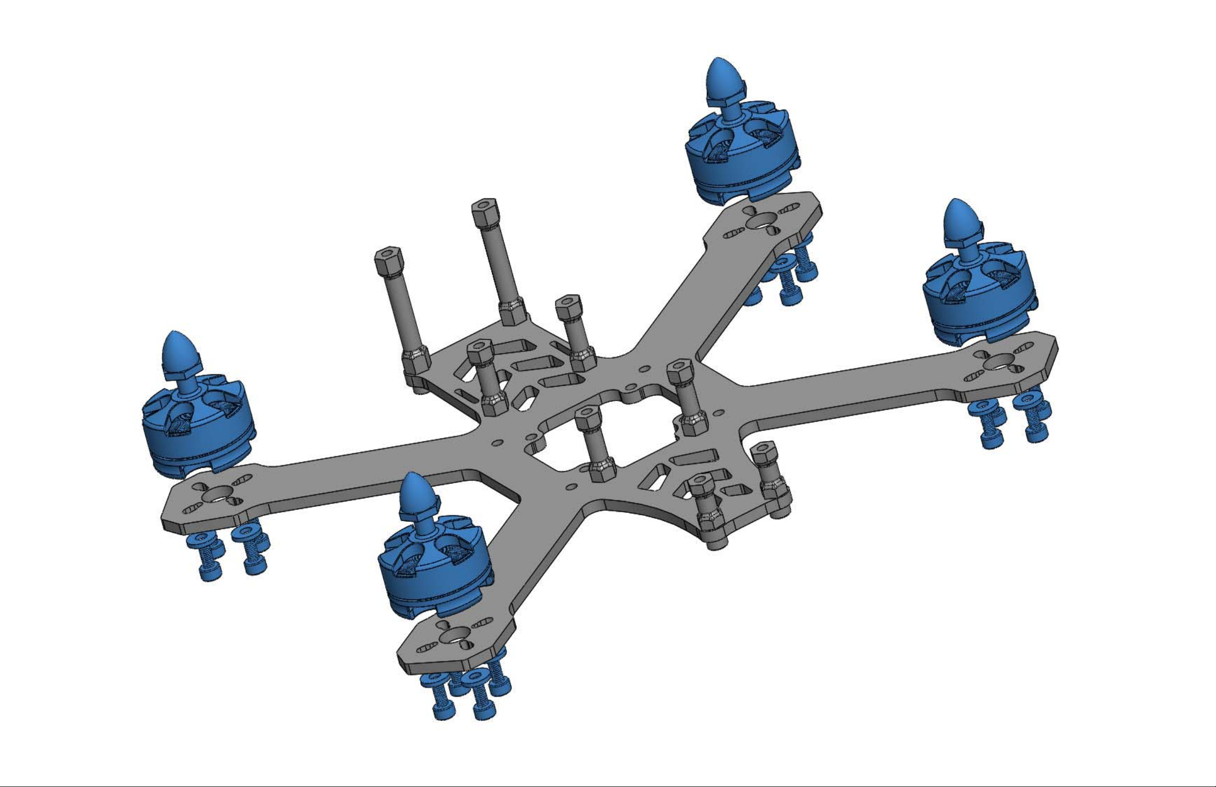
Parts Required:
4 X Outrunner Brushless Motor (Sold Separately)
16 X Socket Head Screw (M3 x 6mm long x blue 7075 aluminum)
16 X Washer (M3 x aluminum)
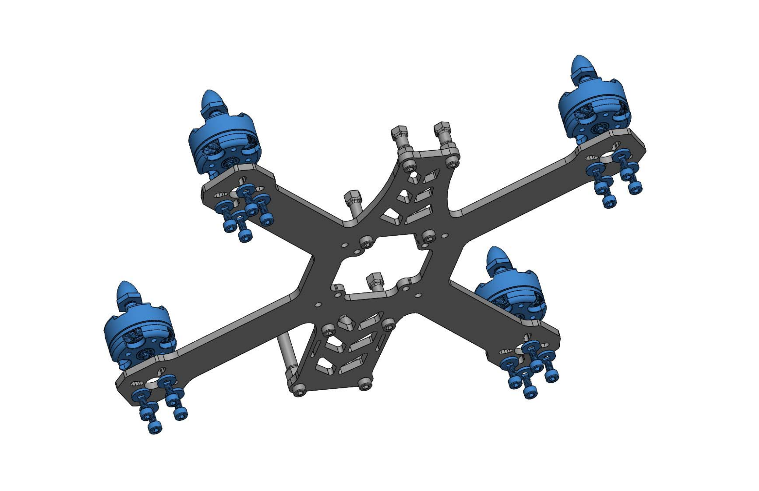
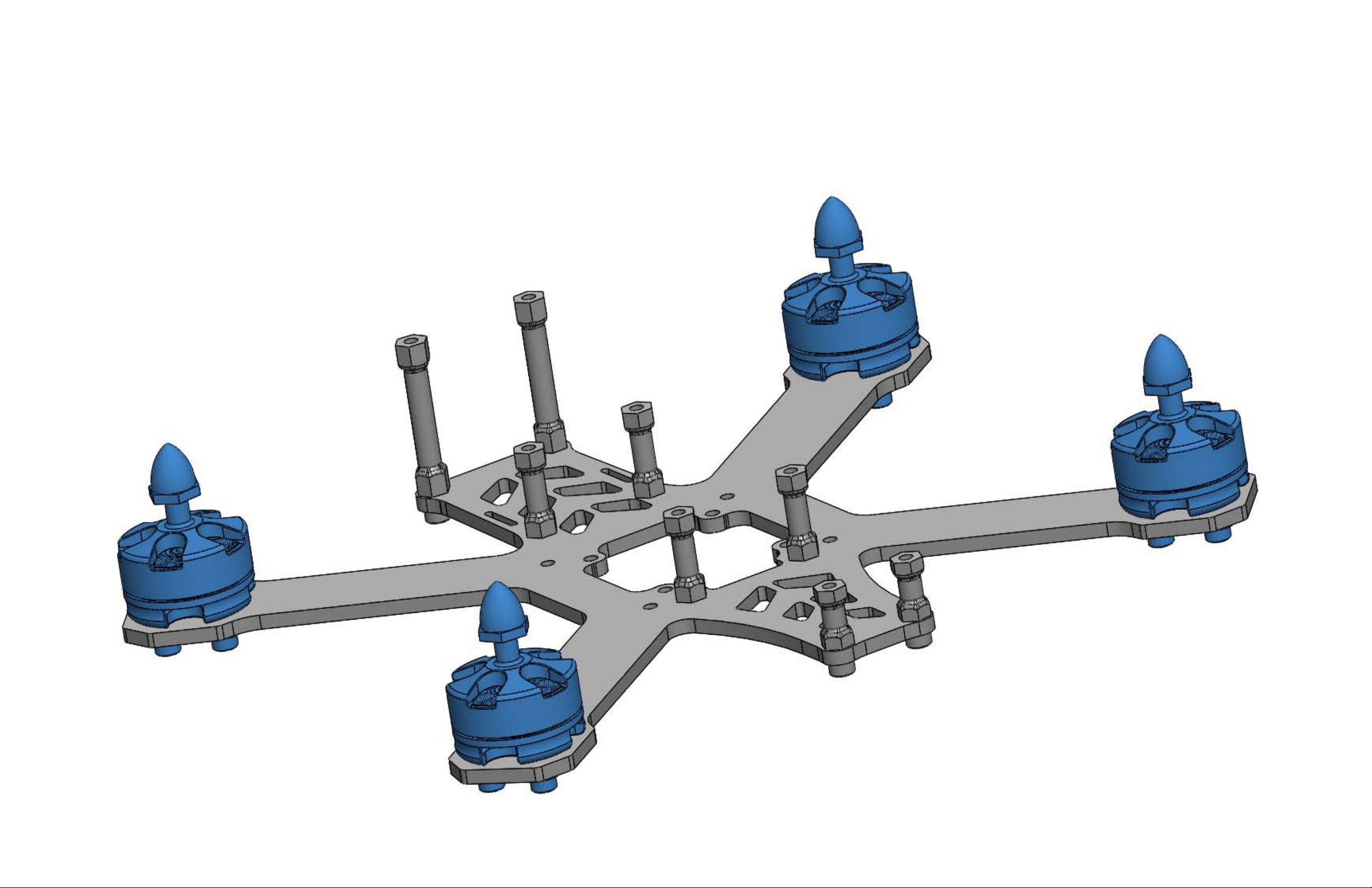
Assembly Process:
Join your motors to the Main Frame Plate as shown below. Use 4 screws and 4 washers per motor. Included in your kit
are M3 screws for this purpose. But, the main frame plate will accept M2 screws for use on smaller 1806 or similar sized
motors. We do not include this size motor mount screw in your kit. You will need to source these on your own. Orient the
motor such that it's wire lead runs straight down the arm.
Page 15
Page 16
Page 17
Page 18

STEP 3
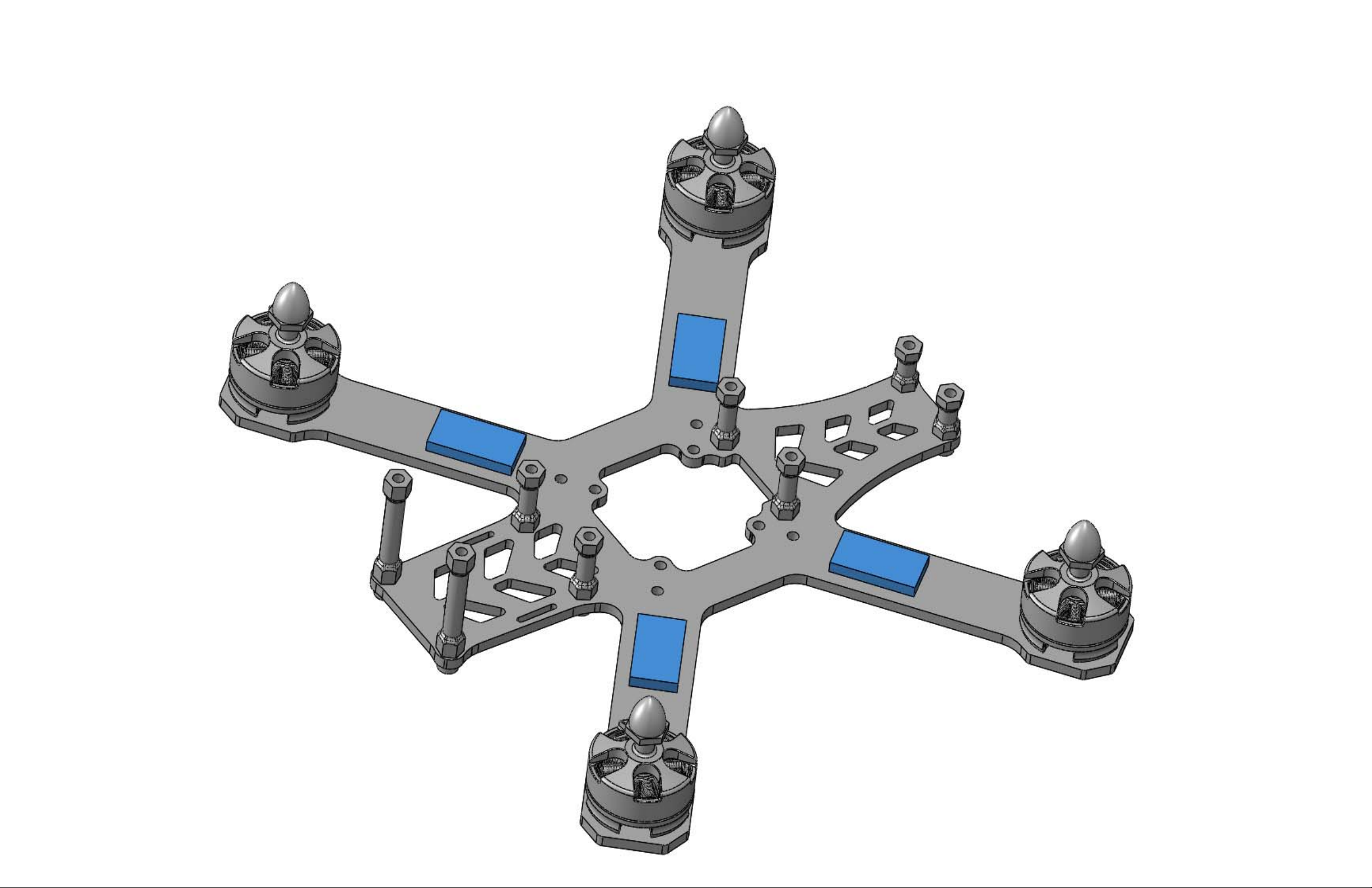
Parts Required:
4 X Electronic Speed Controller (Sold Separately)
Assembly Process:
Please note the ESC's are represented below by the blue rectangles. See our product page for ESC selection
requirements or email us for more information as to what ESC type is best for your 210-R/180-R build. Mount the ESC's
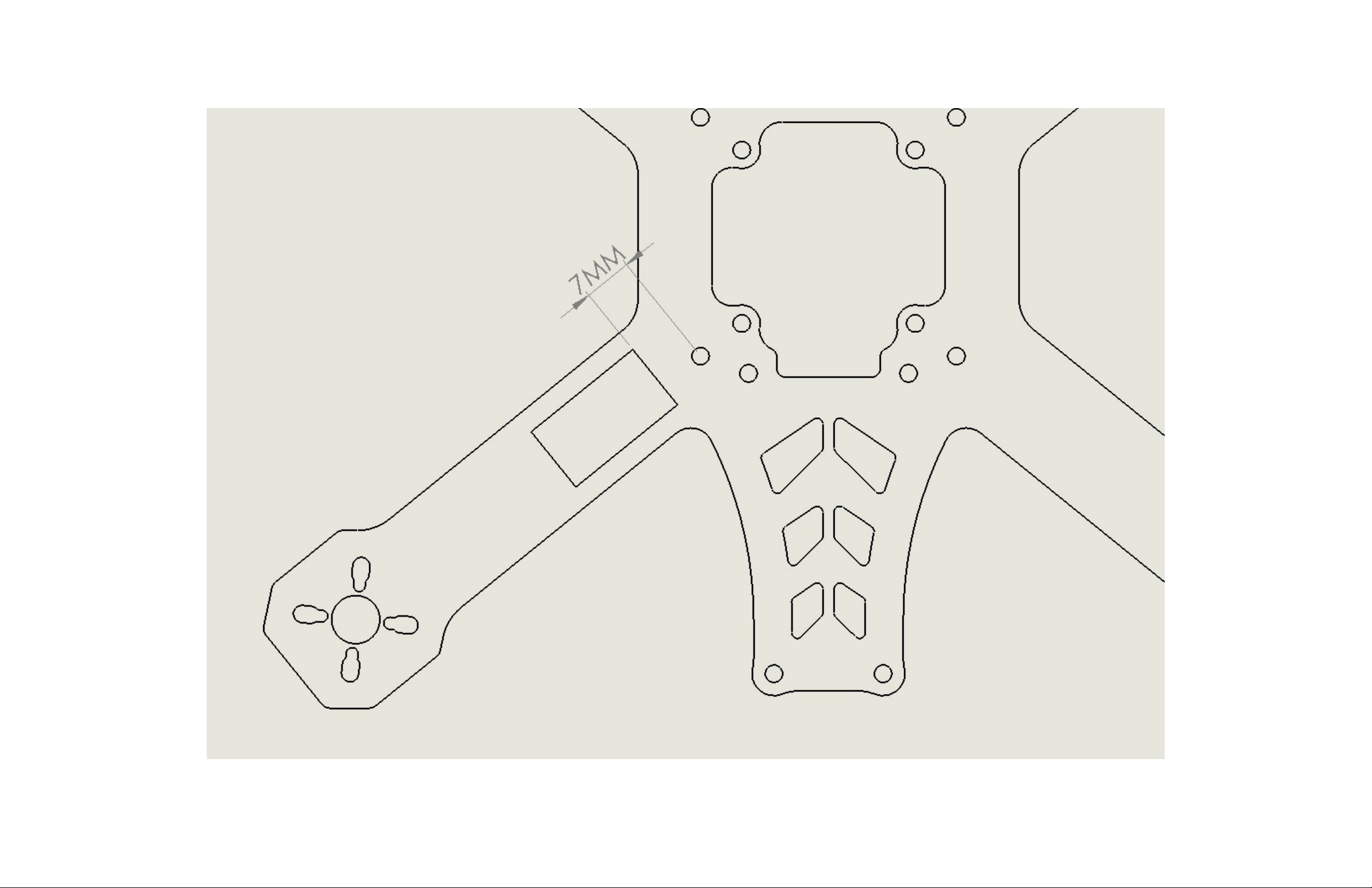
using double sized stick tape. Locate the ESC's so their interior edge is 7mm from the hole shown below. Soldier the
motor to the ESC. But, leave the positive and negative power leads uncut and unsoldiered at this step.
Page 19
Page 20
Page 21

STEP 4
Parts Required:
1 X Catalyst Machineworks FPV PRO Power Distribution Board
1 X 90° Pin Header Set (included with your PDB)
Assembly Process:
We sell the 210-R and 180-R with or without PDB. This assembly step only applies to the included PDB. If you use another
PDB other than our brand you are on your own. If you are using the included Catalyst Machineworks PDB, reference
the manual on our website at:
http://www.catalystmachineworks.com/collections/fpv-racing-equipment/products/catalyst-machineworks-fpvracing-pdb
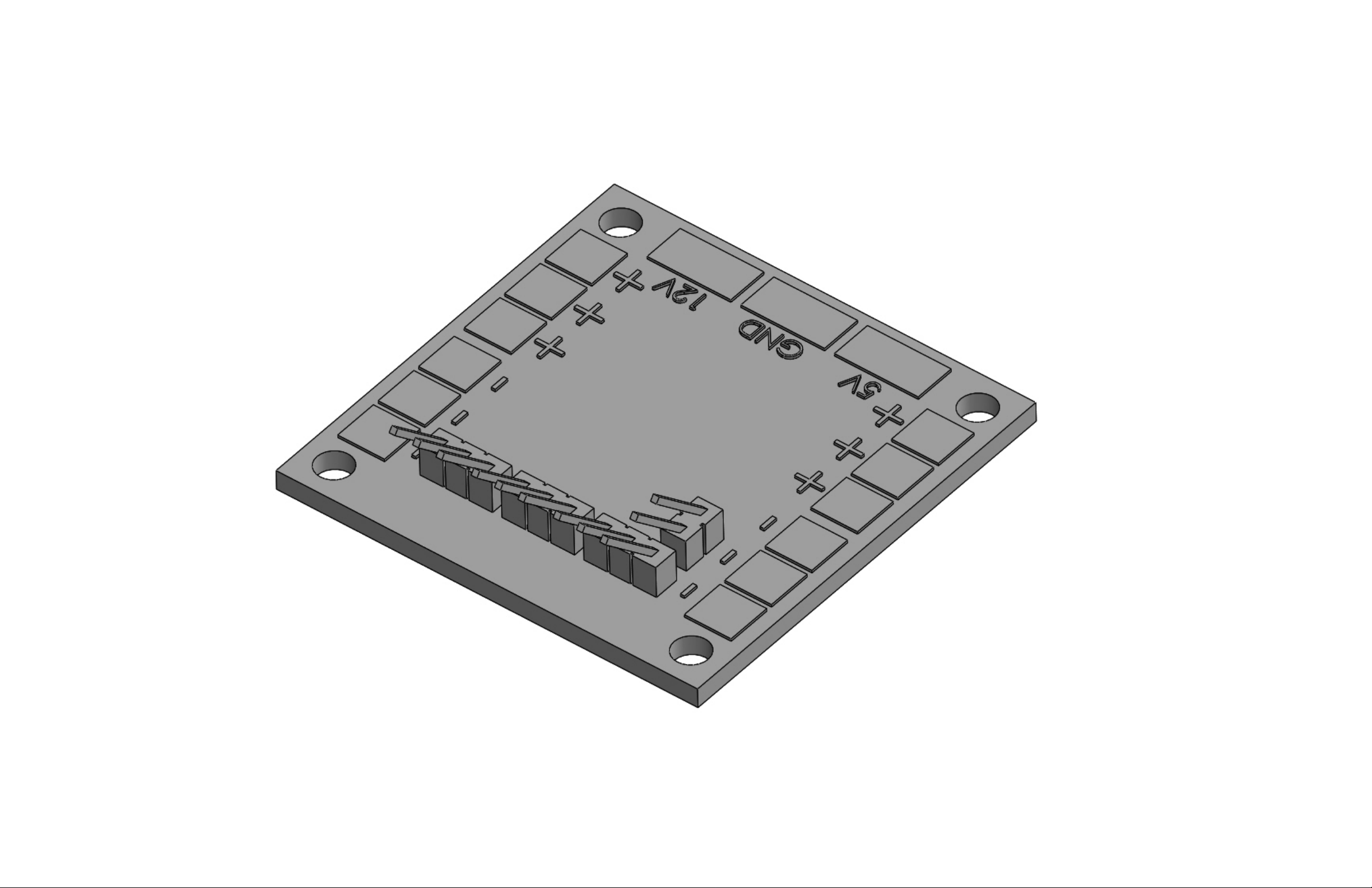
After you have soldiered the pin headers per the PDB manual it will be necessary to bend them slightly upwards as
shown in the graphic below. You can use some needle nose pliers to bend each header up by 20 degrees or so. This
will aid in wire management later in the build.
Page 22
Page 23

STEP 5
Parts Required:
1 X Lipo Pigtail and XT60 Connector (Sold Separately)
1 X Grommet for XT60
Assembly Process:
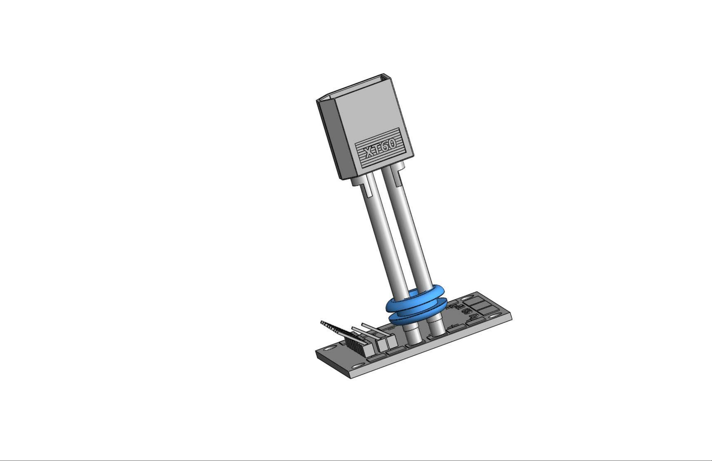
Soldier your lipo battery pigtail (positive and negative wire leads) to the PDB board positive and negative pads. Be sure
to install the XT60 grommet over your wires as shown below prior to soldiering on your XT60 connector. Make sure the
pigtail is located on the right side of the board as shown in the graphic below. You should use 14 gage wires. The wires
should be cut to 60mm. Your wire ends should come straight off the PDB pads, pointing straight up. It may be
necessary to install some extra shrink tubing around the base of the wires to protect them from any sharp edges in the
main frame plate.
Page 24
Page 25

STEP 6
Parts Required:
1 X Assembled PDB (from previous step)
1 X Assembled Main Frame Plate (from step 1)
4 X Flight Controller/FC Mount Screw (Black plastic M3 thread x 10mm long)
4 X PDB Spacer (Black plastic M3 hole)
4 X Flight Controller Hex Standoff (Black plastic M3 thread x 10mm long)
Assembly Process:
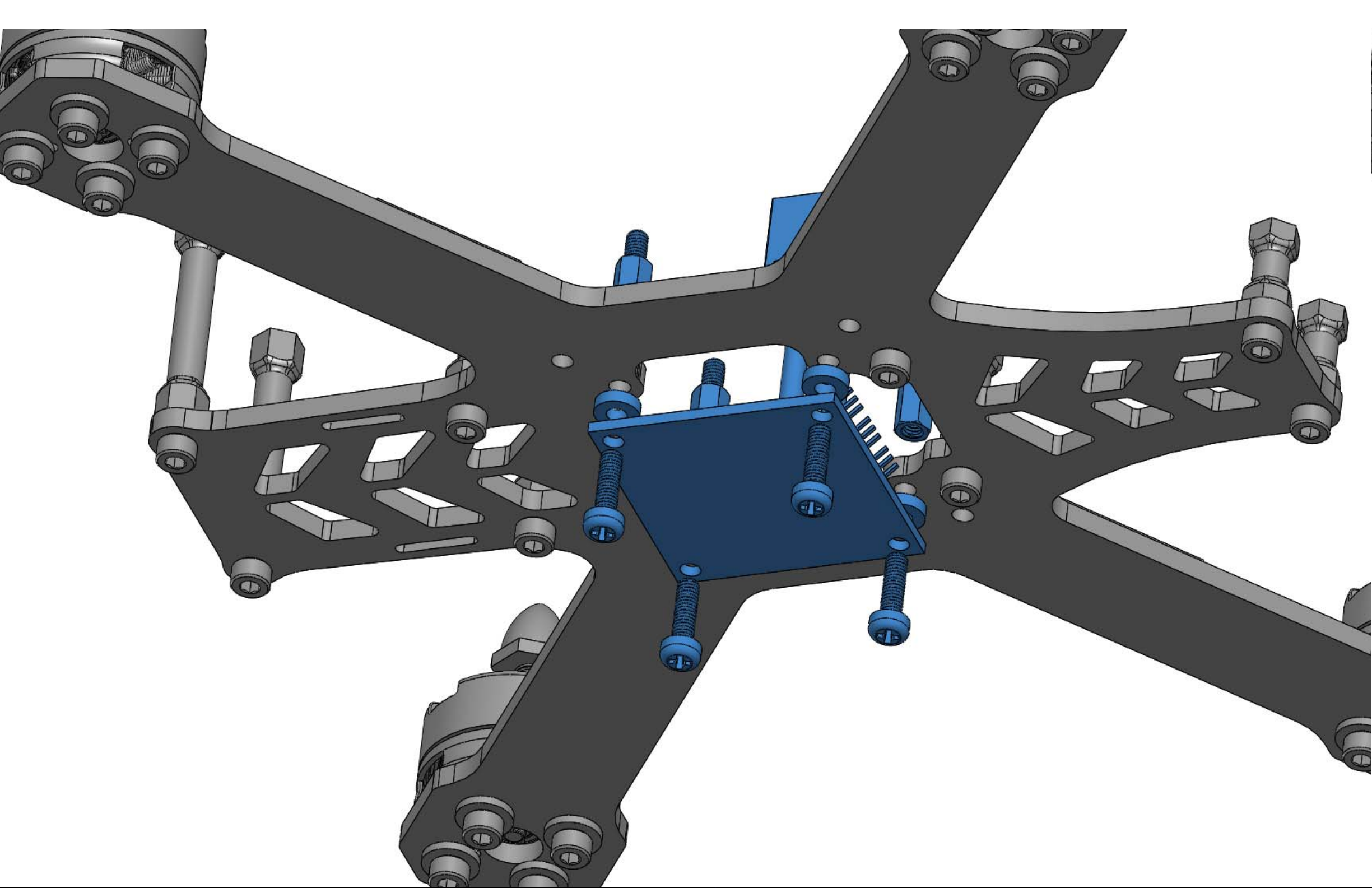
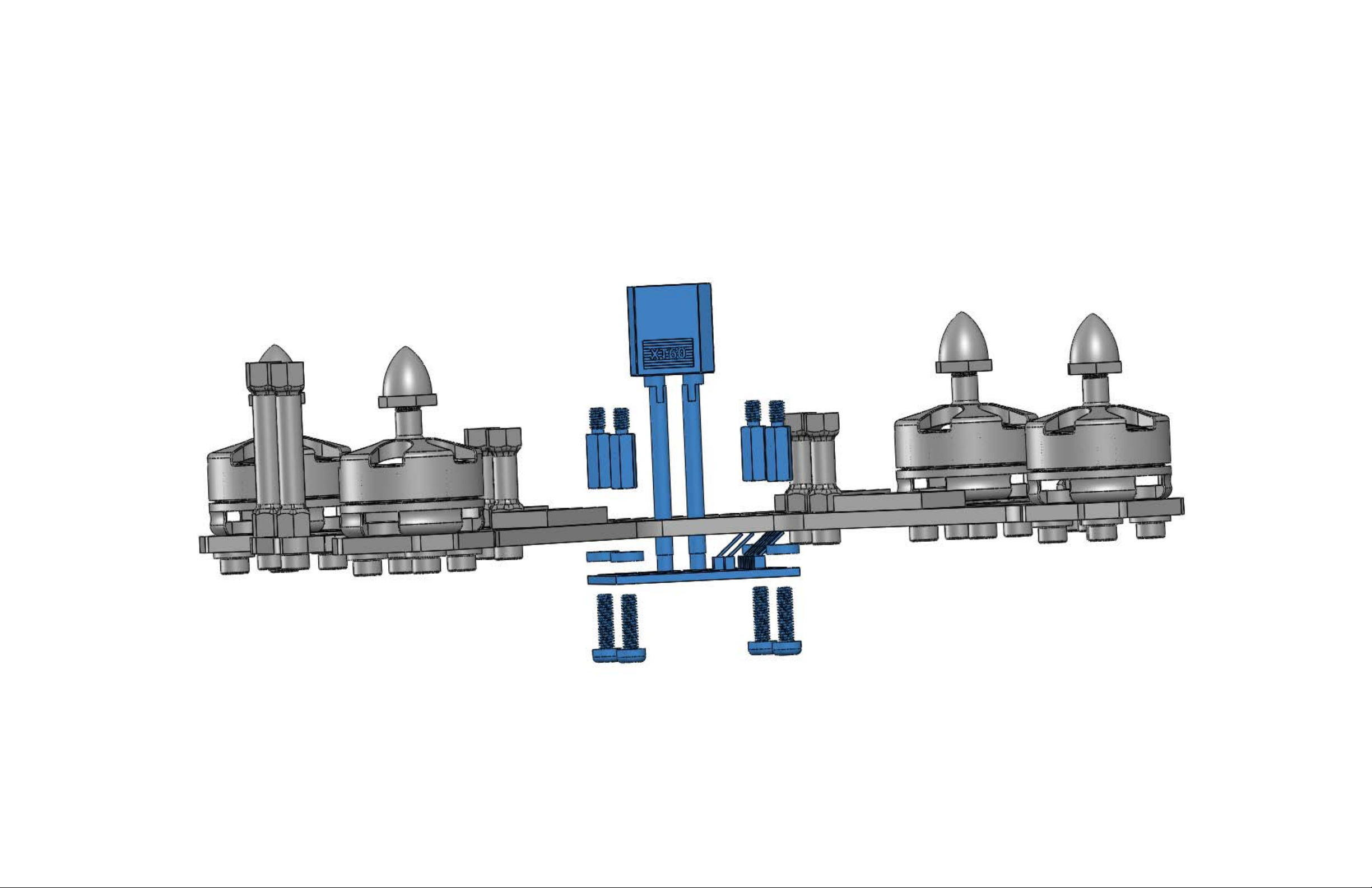
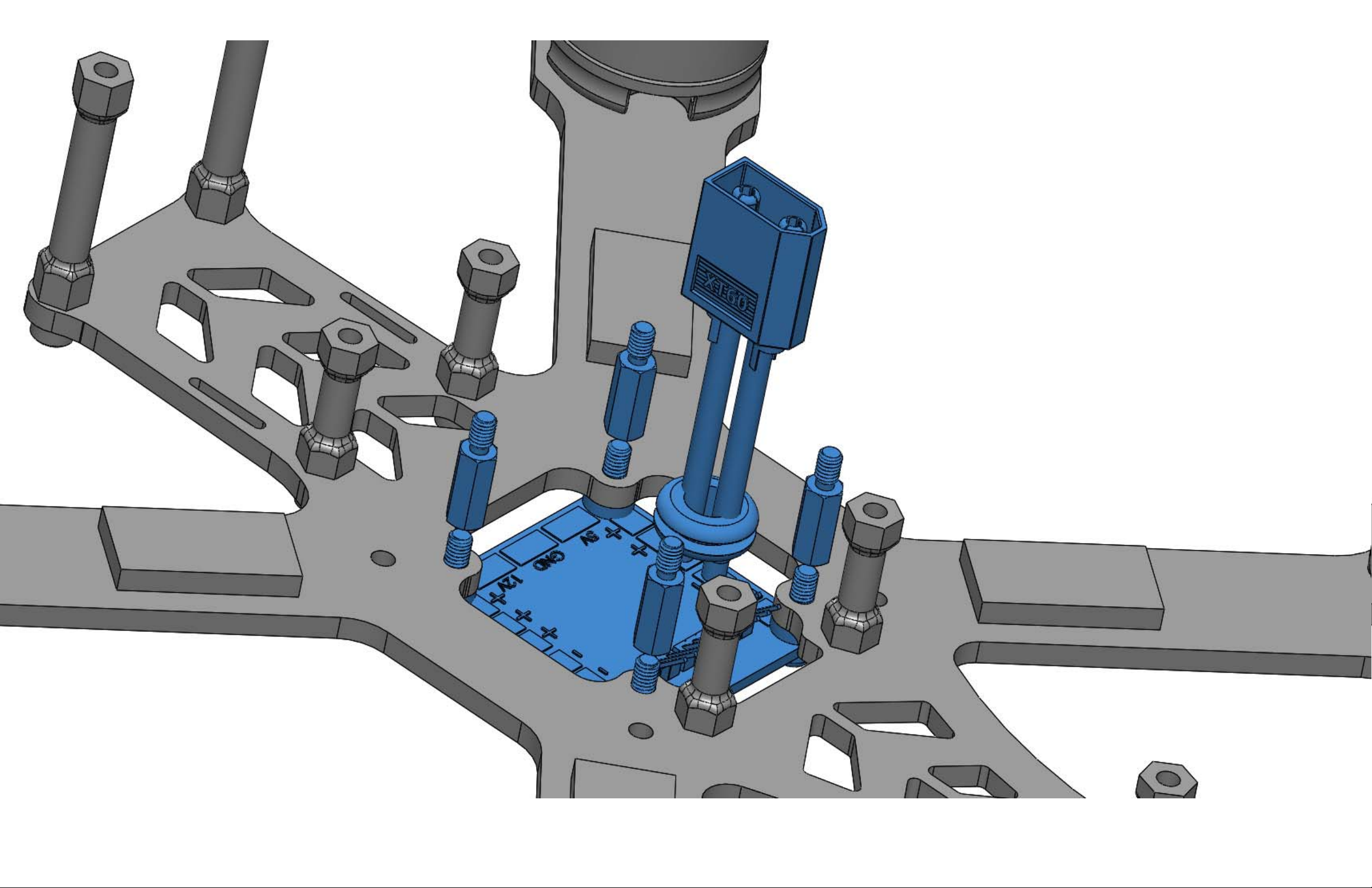
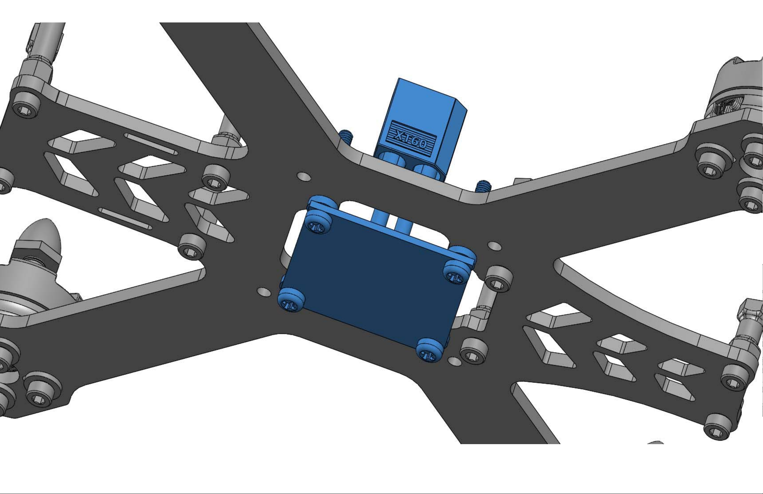
Install the PDB to the bottom of the main frame plate as shown. Be sure to use the PDB spacers to separate the PDB
from your carbon fiber main frame plate or you may short out the board.
Page 26
Page 27
Page 28
Page 29
Page 30

STEP 7
Assembly Process:
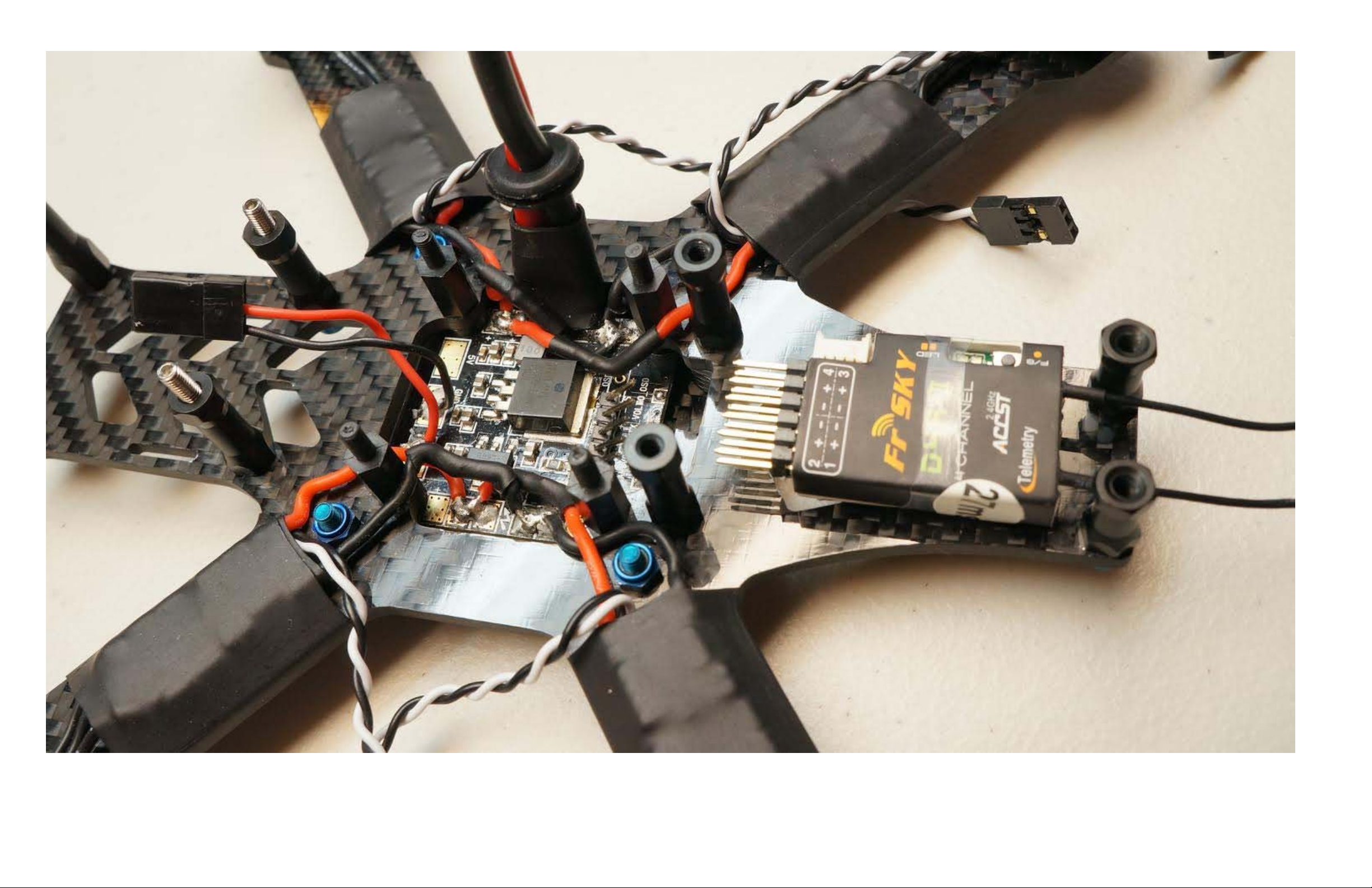
This is a very important step in your build. Here you will soldier the open leads from the ESC's to the PDB. Take your time
and plan this out. Wire management is very important. Provide enough slack on each ESC wire lead so it doesn't rub up
against the main frame plate. But, not too much excess slack as to result in a messy build! If your wires are too long you
may find it difficult to install the rest of the components later in the build. Since you are soldiering the ESC leads with the
PDB installed it helps greatly to use a soldier gun with a fine tip. BE CAREFUL not to get too close to the plastic FC
standoffs or you may damage them with your soldier gun. At this step you can also cut down the ESC signal leads that
run to your flight controller (black and white wires in the picture below). This is important, because most ESC's come
with signal leads that are too long resulting in excess wire. Test fit your FC and determine how long you want these
signal leads to be. Cut then re-soldier the leads to reduce their length.
Page 31
Page 32

STEP 8
Parts Required:
1 X PDB Bay Guard (Black 3D Printed ABS Plastic)
1 X PDB Bay Cover Plate (1.5mm CF)
4 X PDB Guard Inserts (Silver Aluminum M3 Hole x 4.5mm OD x 6mm long)
4 X Socket Head Screw (M3 x 16mm long x blue 7075 aluminum)
4 X Nut (M3 x blue 7075 aluminum)
Assembly Process:
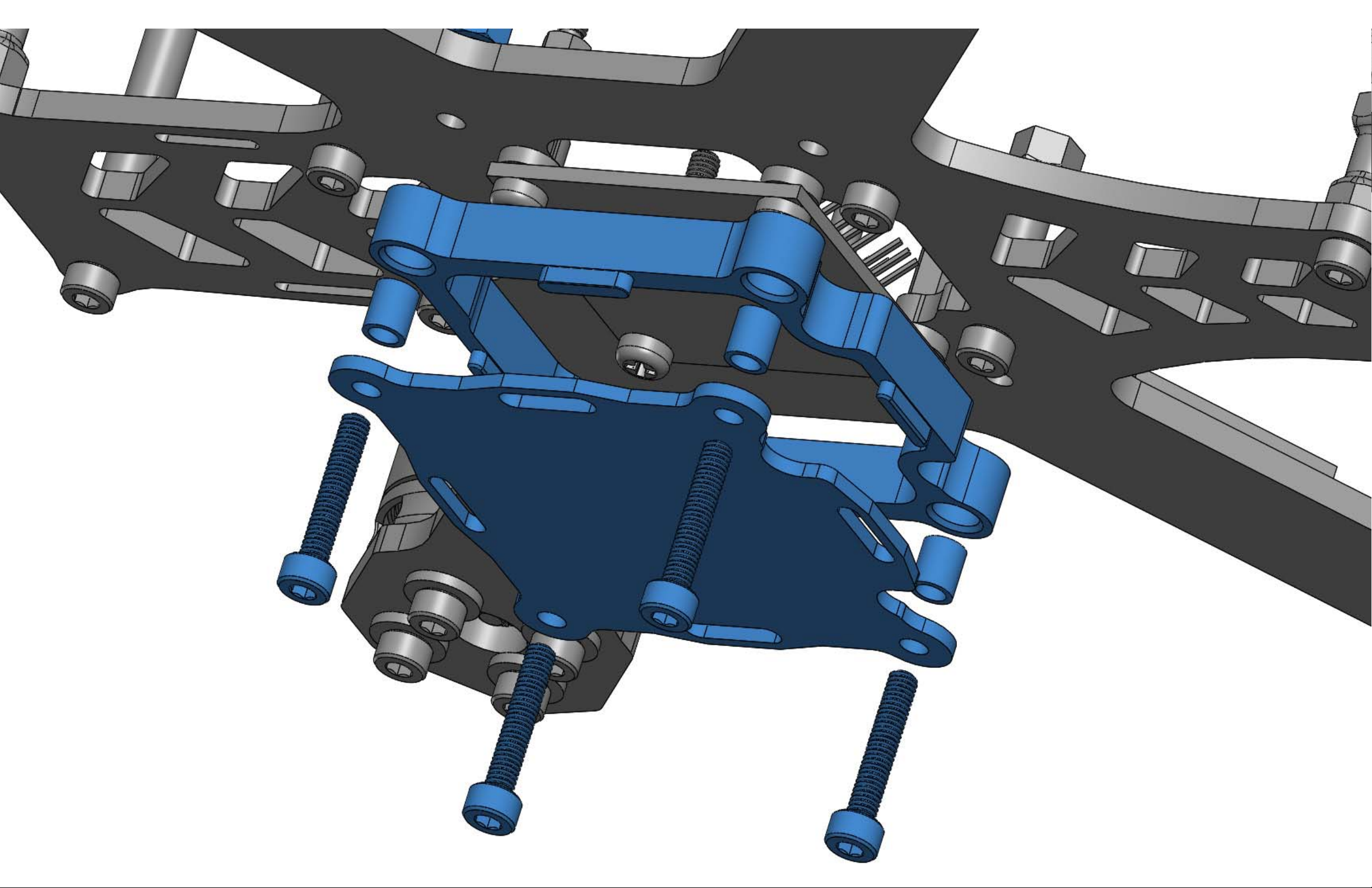
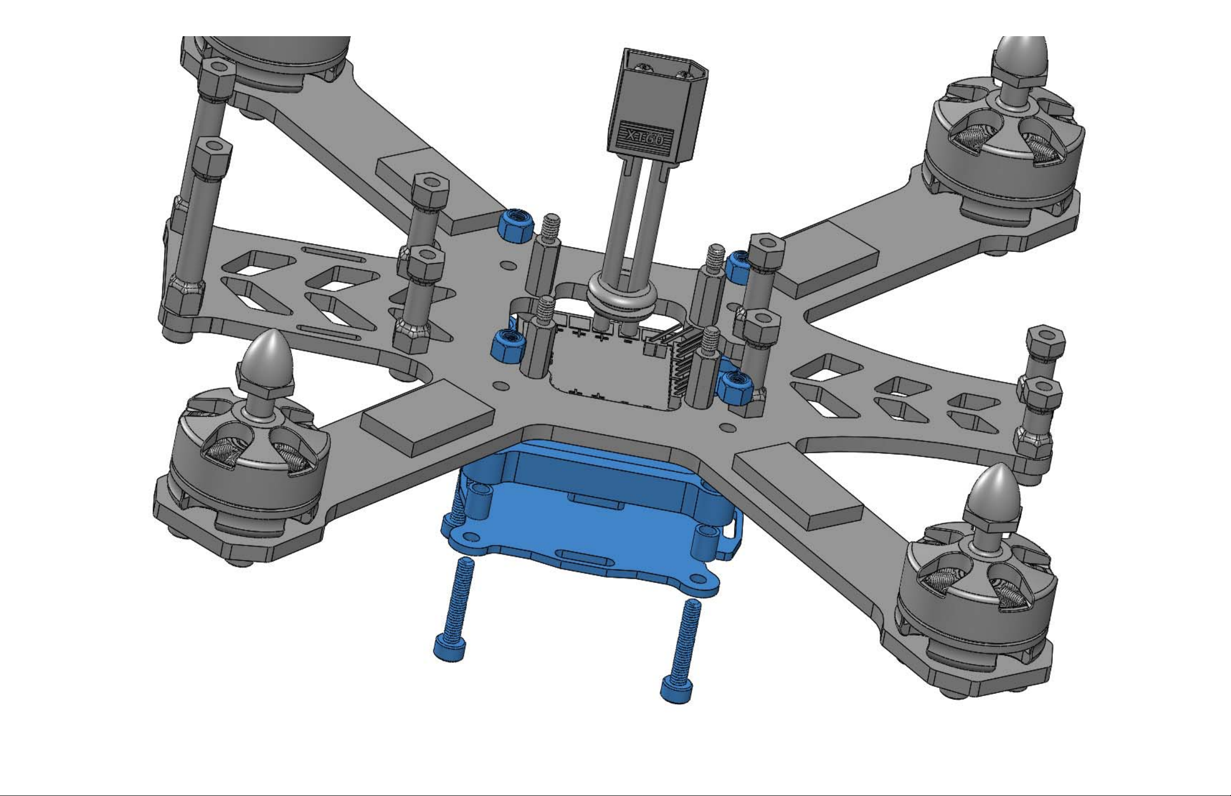
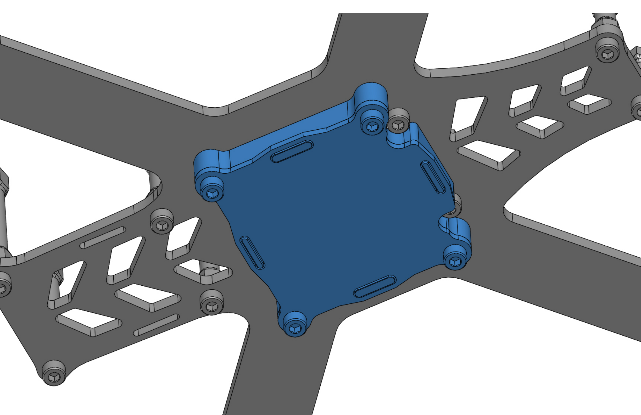
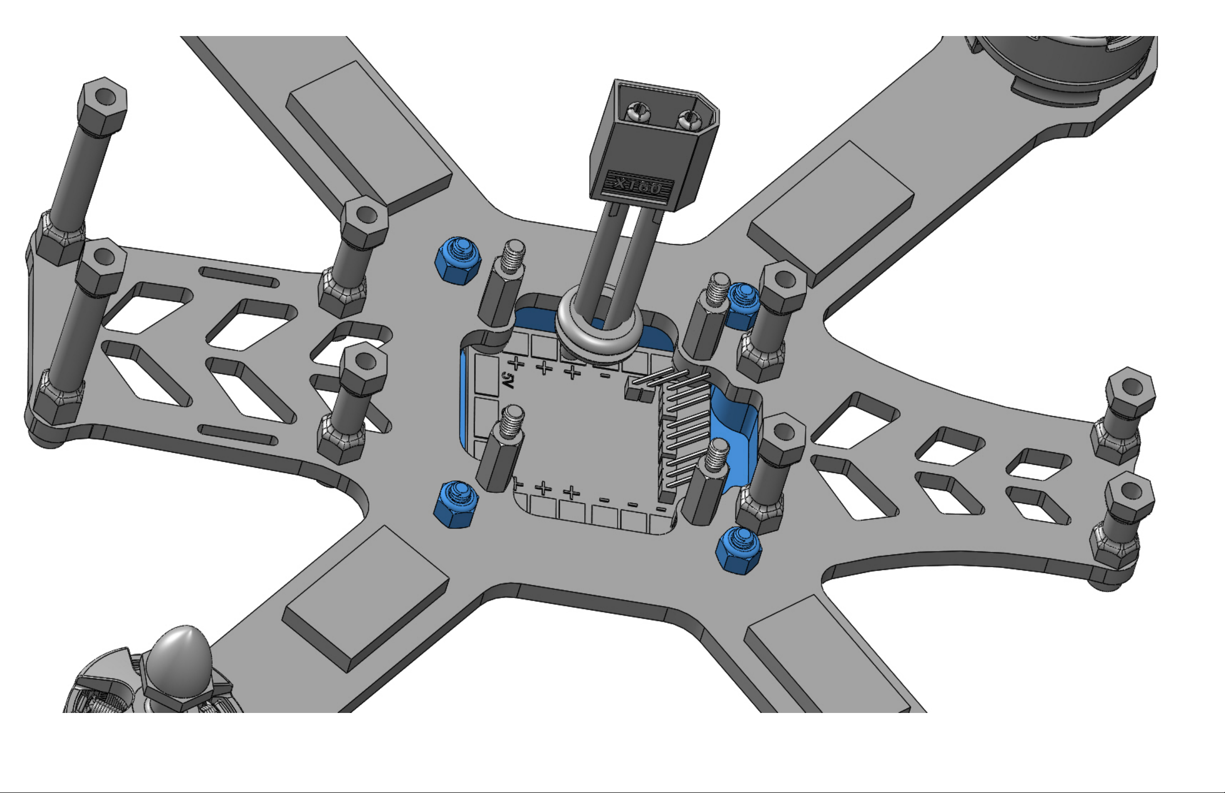
Press the 4 PDB Guard Inserts into the 4 PDB Bay Guard holes. Then install the PDB Bay Guard onto the main frame plate
as shown using the supplied fasteners.
Page 33
Page 34
Page 35
Page 36
Page 37

STEP 9
Parts Required:
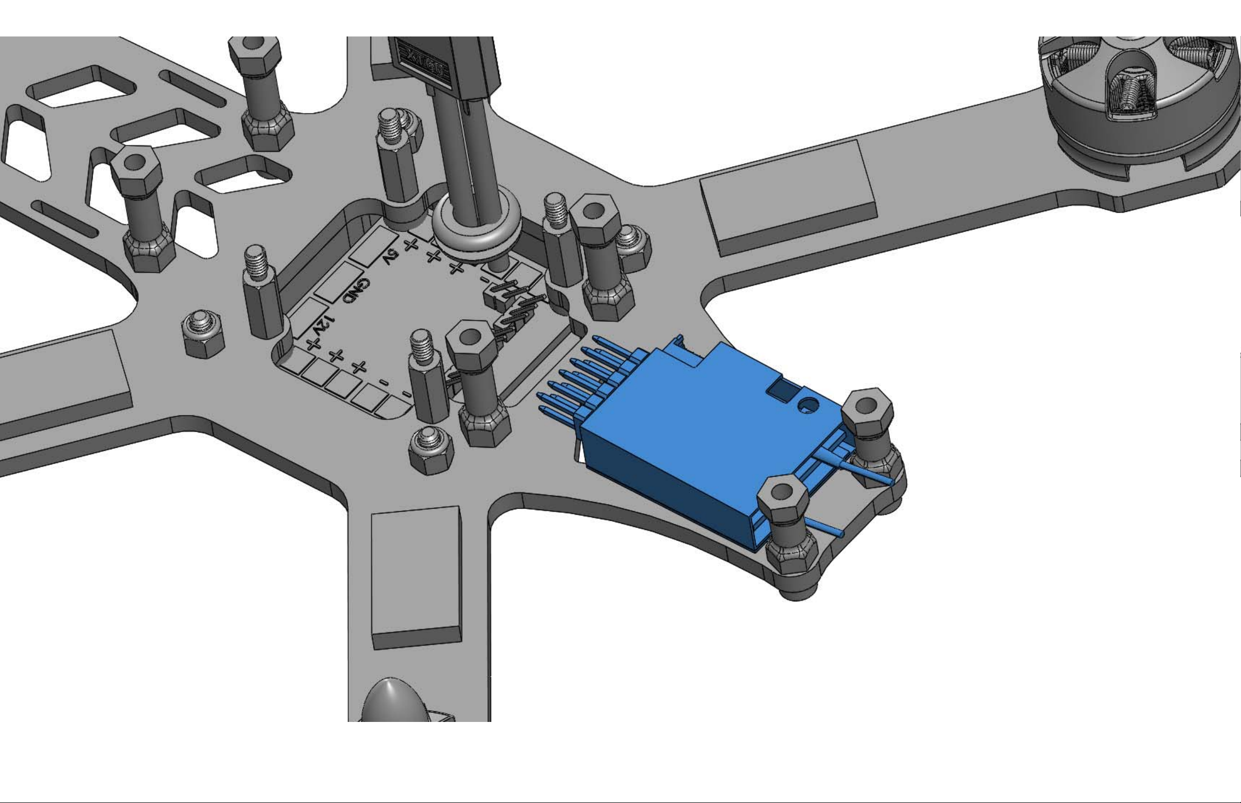
1 X RC Receiver (Sold Separately)
Assembly Process:
Install your receiver using double sided stick tape as shown. Be sure to orient the antenna toward the rear of the craft.
Page 38
Page 39

STEP 10
Parts Required:
1 X Top Fuselage Plate (1.5mm CF)
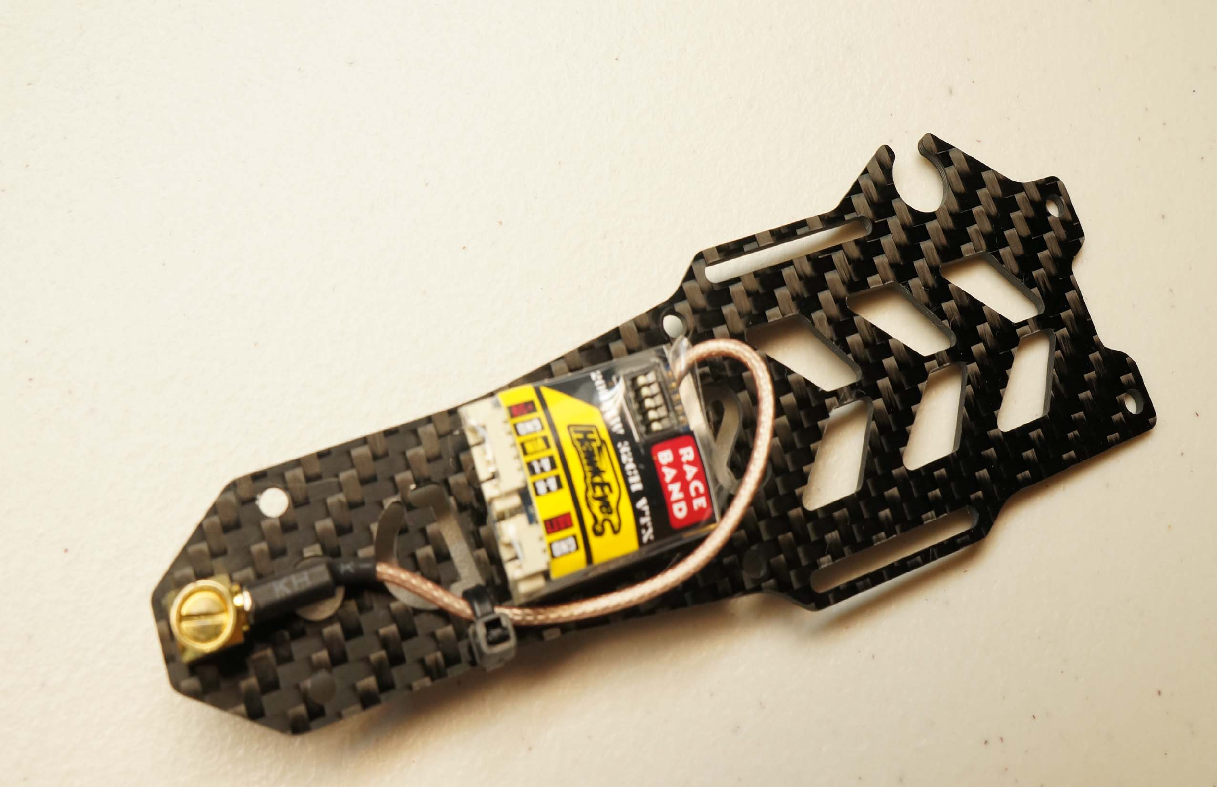
1 X FPV Video Transmitter (Sold Separately)
1 X SMA right angle connector and pigtail (If using a Vtx without integrated SMA pigtail)
Assembly Process:
Install the FPV Vtx onto the Top Fuselage Plate as shown using double sided stick tape. A zip tie may be necessary to
hold the SMA pigtail to the plate. A Vtx such as the Hawkeye unit is ideal due to it's integrated 10cm SMA pigtail. You
can use a Vtx without an integrated SMA pigtail, but your adapter must be the proper length to reach the FPV
antenna mount hole.
Page 40
Page 41

STEP 11
Parts Required:
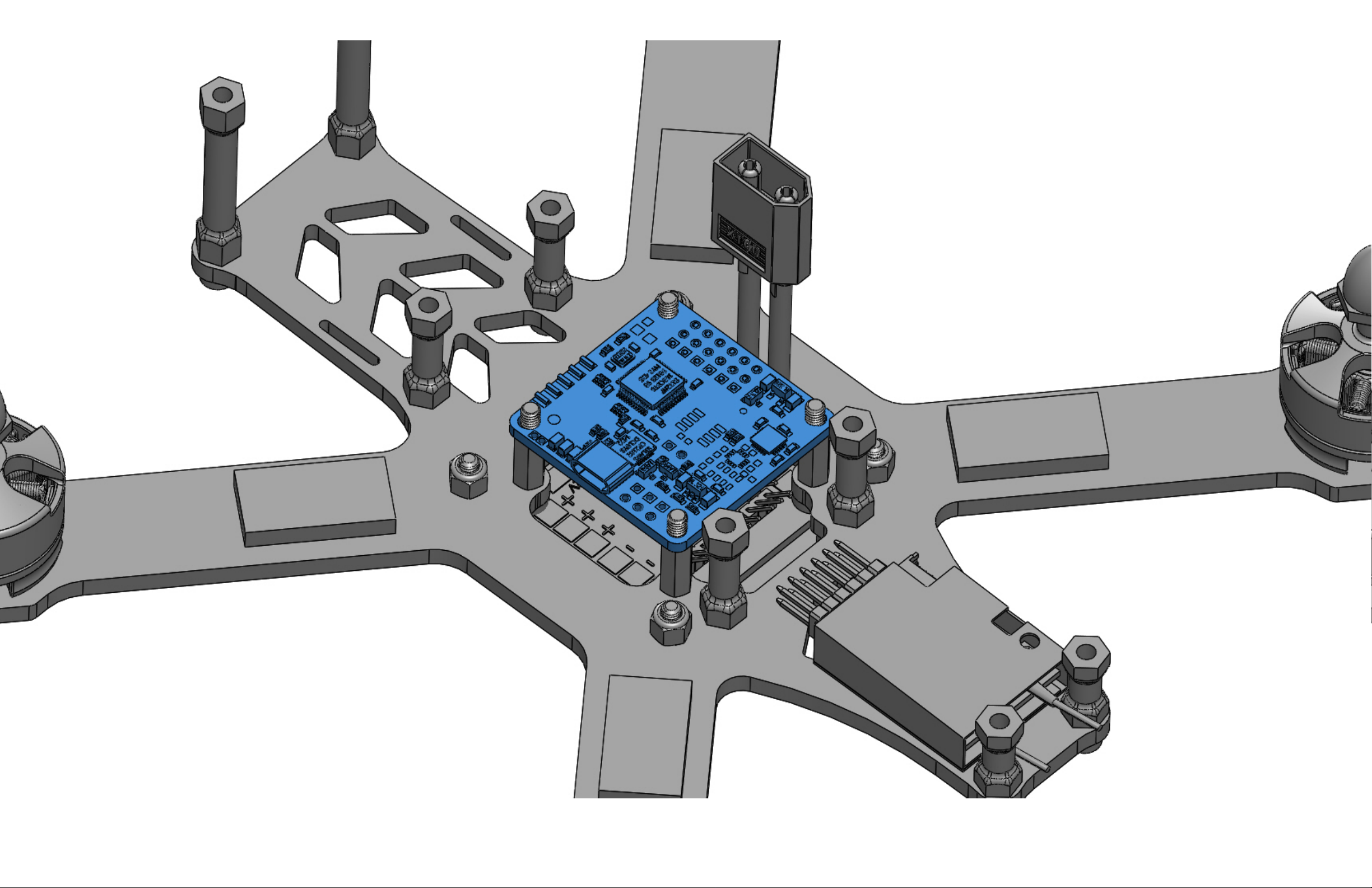
1 X Flight Controller (Sold Separately)
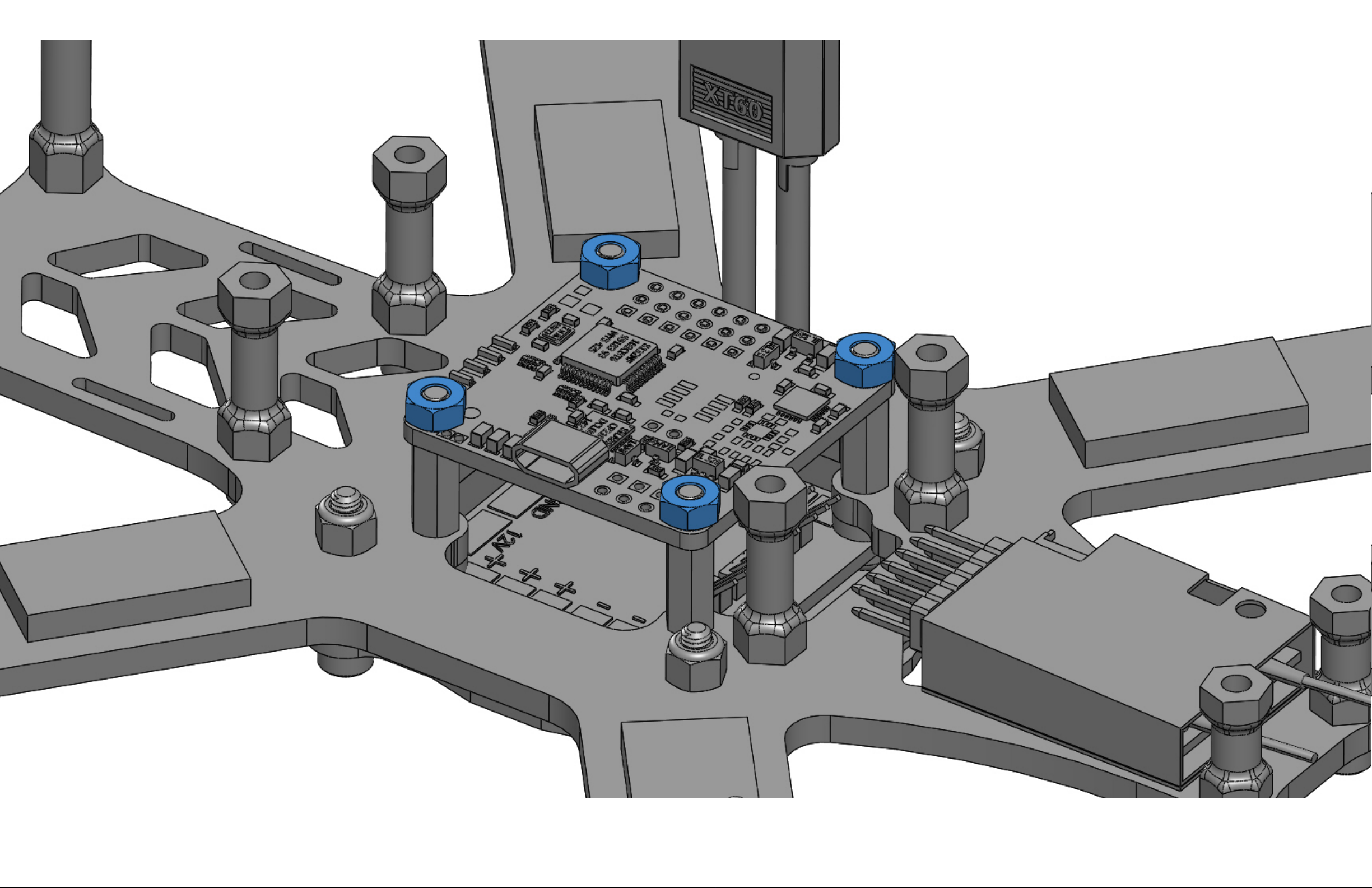
4 X Flight Controller Nut (Black plastic M3 thread)
1 X Assembled Top Fuselage Plate (from previous step)
Assembly Process:
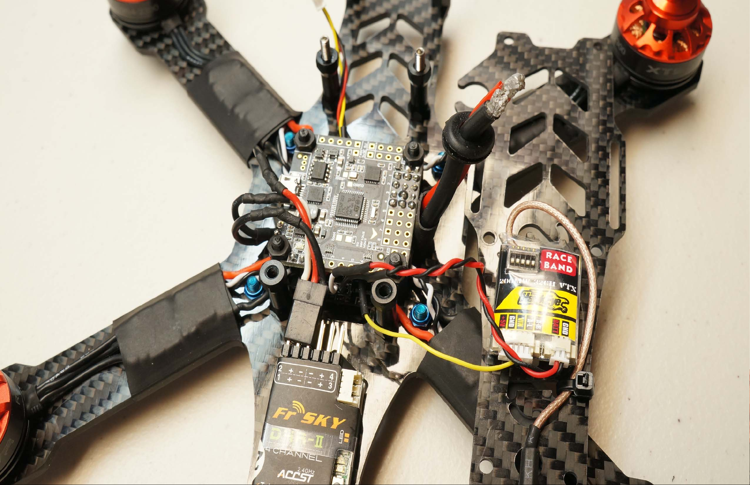
Once you have all your wiring connected to the PDB and FC, install the FC down onto the standoffs as shown using the
4 plastic M3 nuts.
Page 42
Page 43
Page 44
Page 45

STEP 12
Parts Required:
1 X Assembled Top Fuselage Plate (from previous step)
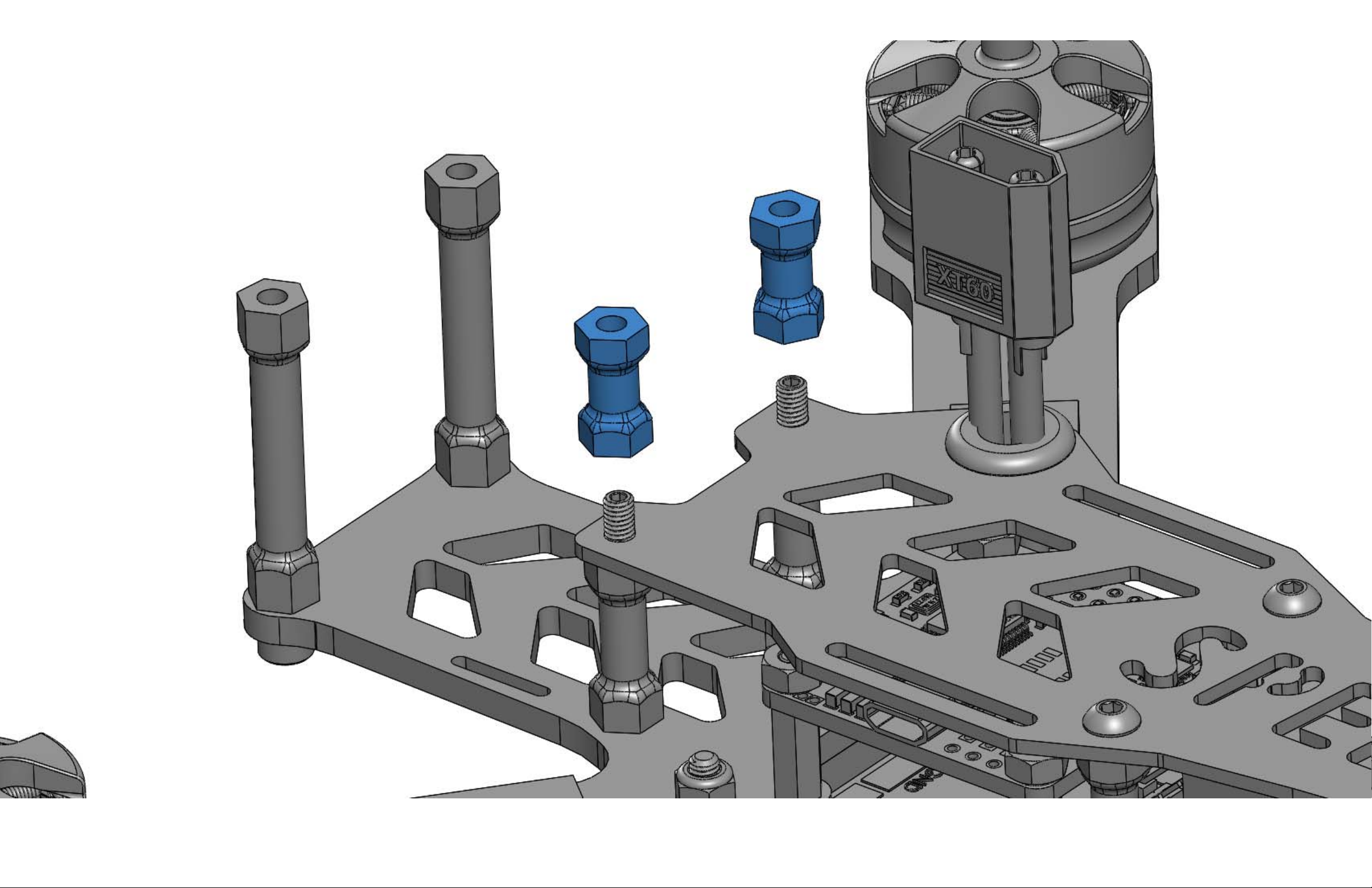
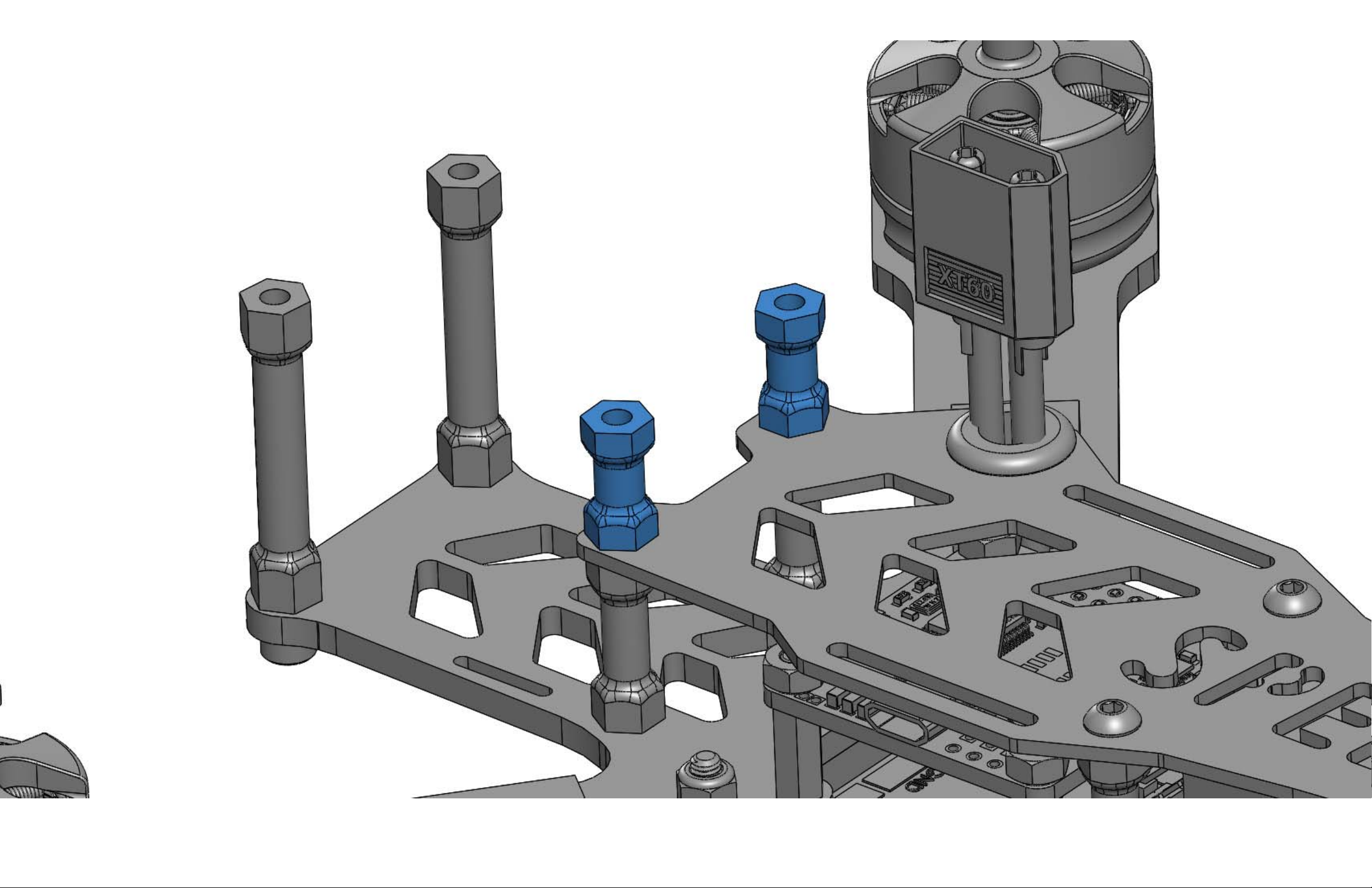
2 X Set Screw (M3 x 10mm long x steel)
2 X Button Head Screw (M3 x 6mm long x blue 7075 aluminum)
2 X Standoff (Black aluminum M3 thread x 12.5mm long)
1 X Velcro Lipo Strap – Catalyst Machineworks
Assembly Process:
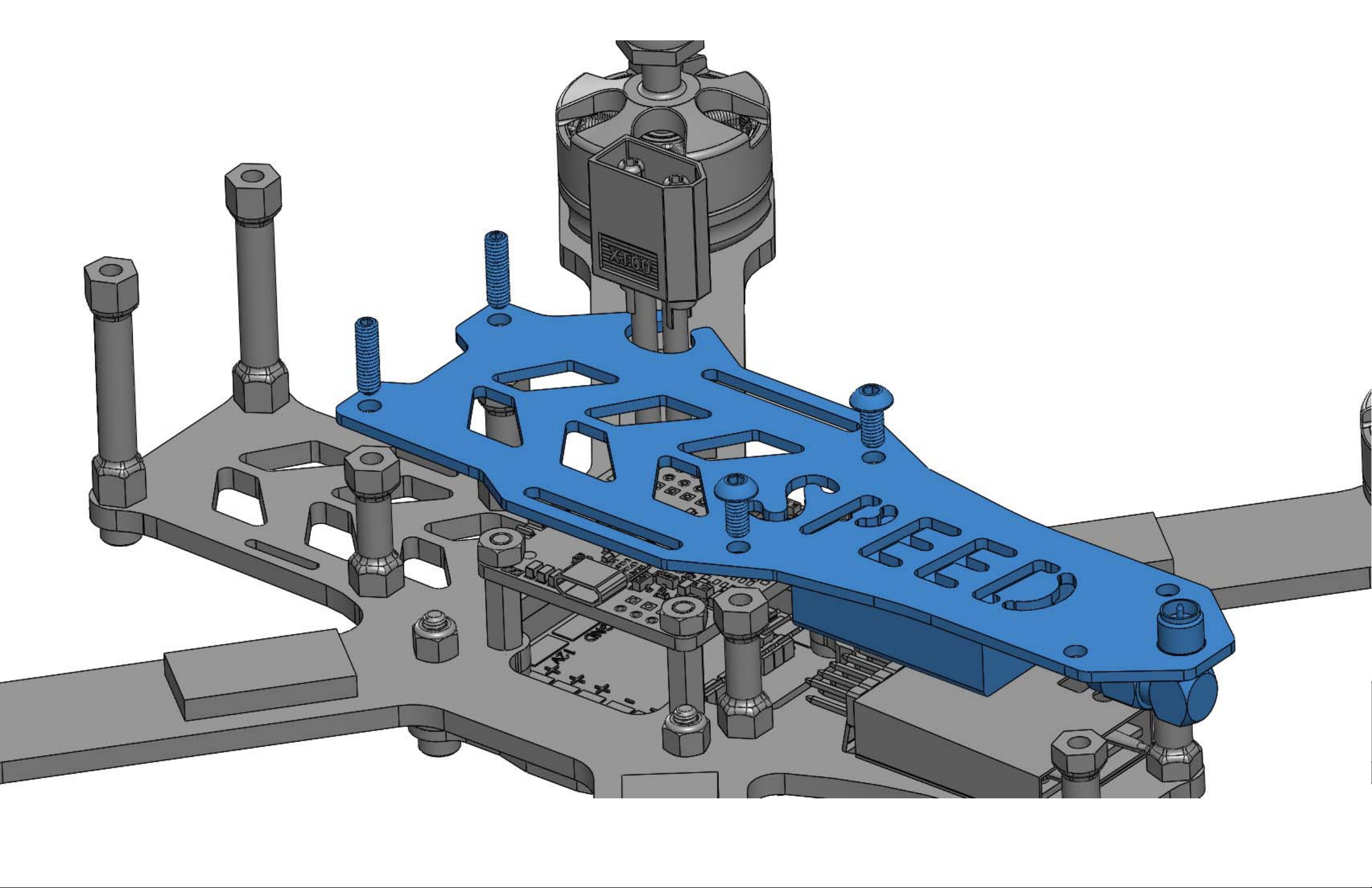
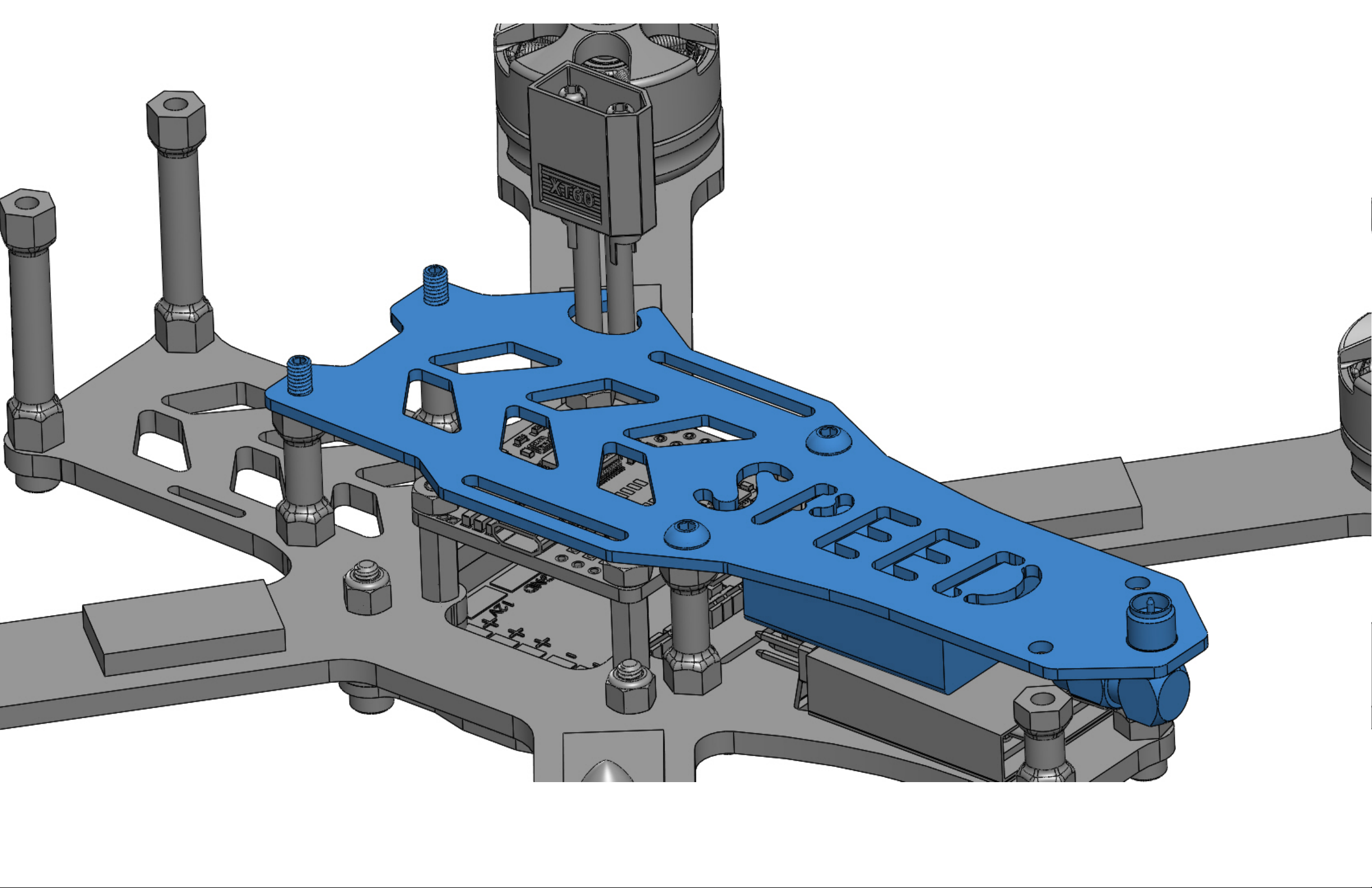
Run the included velcro strap through the slots in the Top Fuselage Plate (not shown pictorially below). With the Vtx
wired up, install the Top Fuselage Plate onto the main frame as shown. Install the set screws so 4mm of thread length is
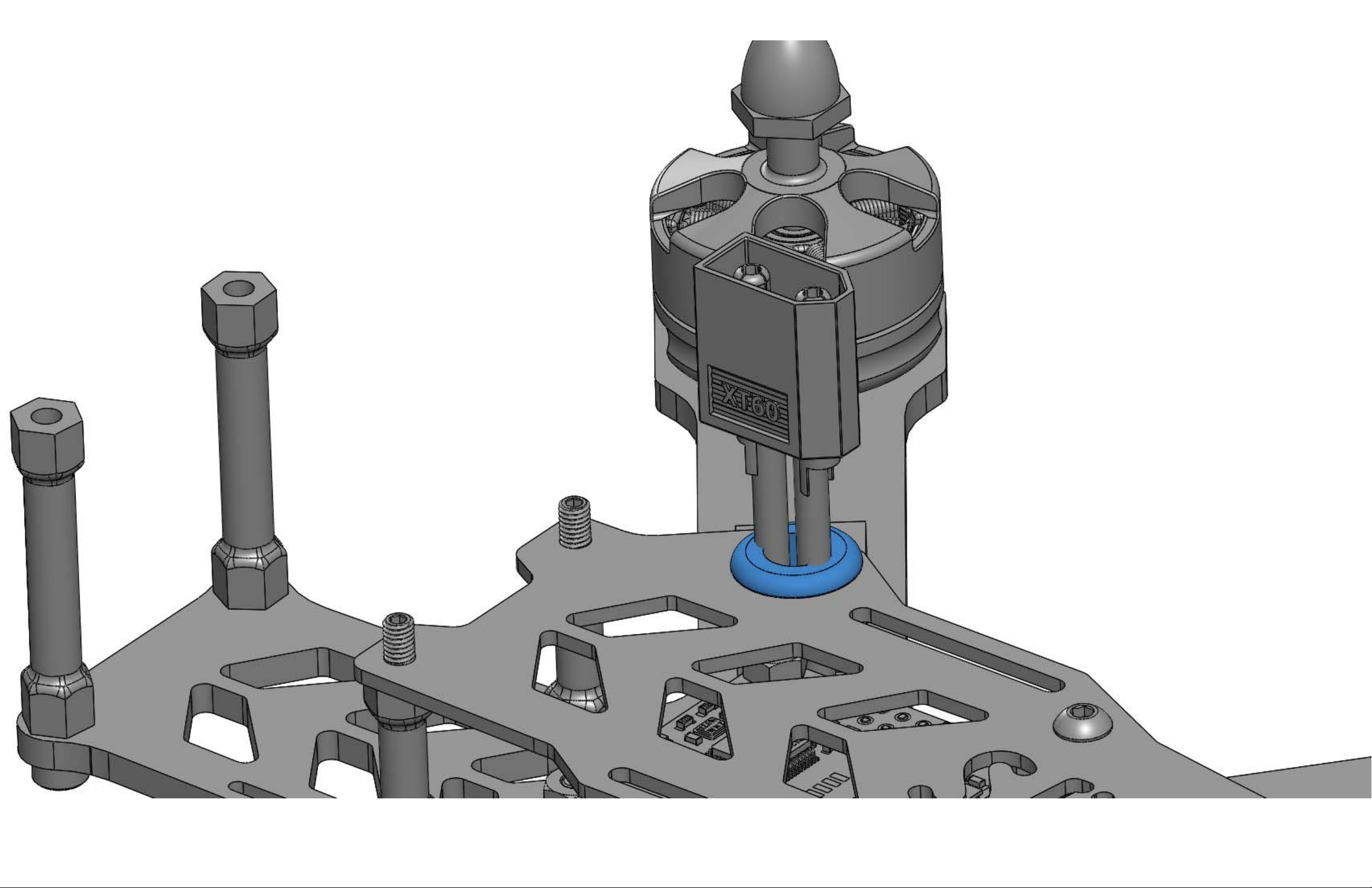
exposed and use loctite on these screws. Install the M3 button head screws as shown. Press the XT60 grommet into the
oval slot in the side of the Top Fuselage Plate. This grommet works to hold your lipo pigtail in the correct location. Install
both standoffs as shown.
Page 46
Page 47
Page 48
Page 49
Page 50
Page 51

STEP 13
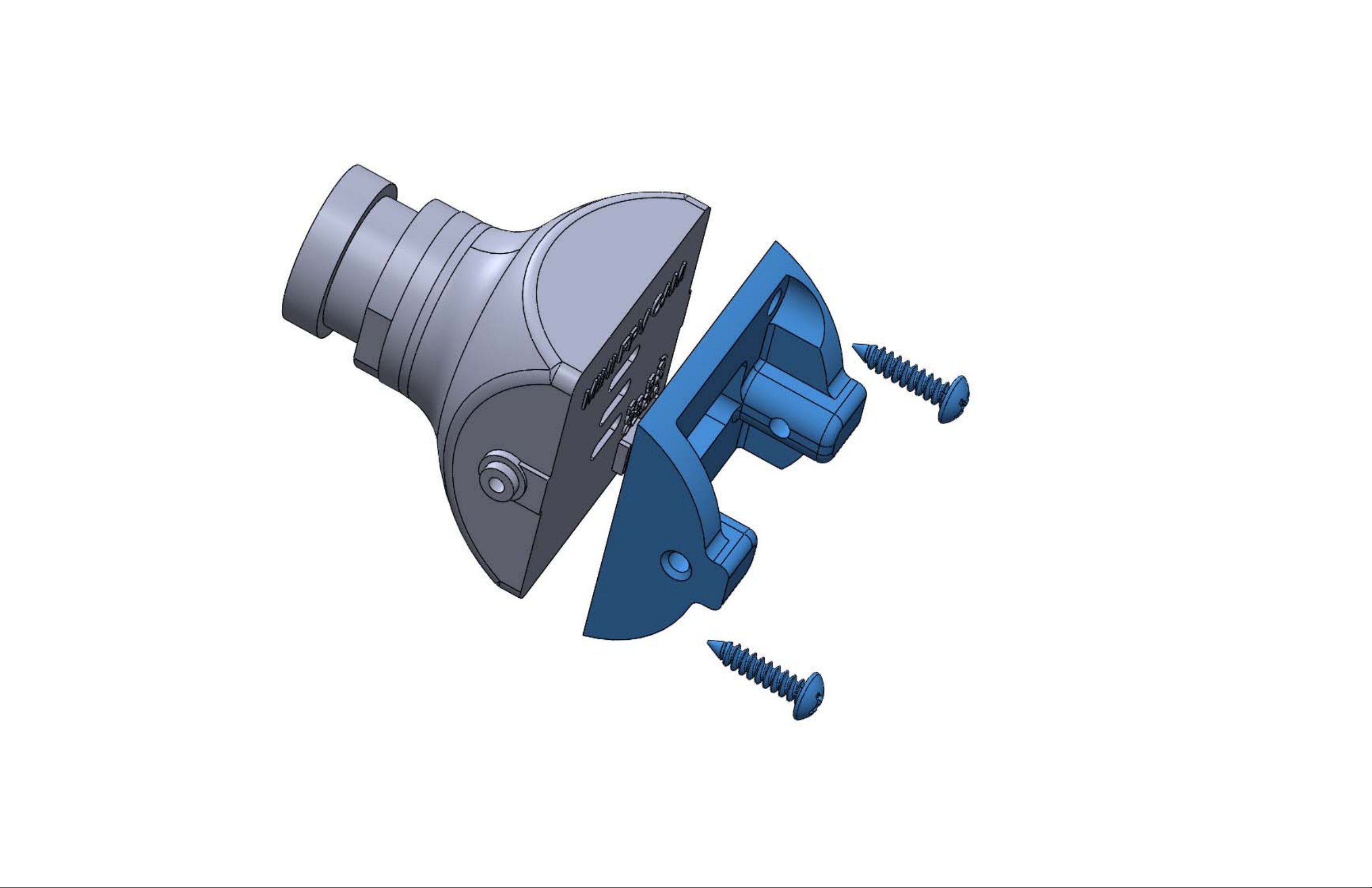
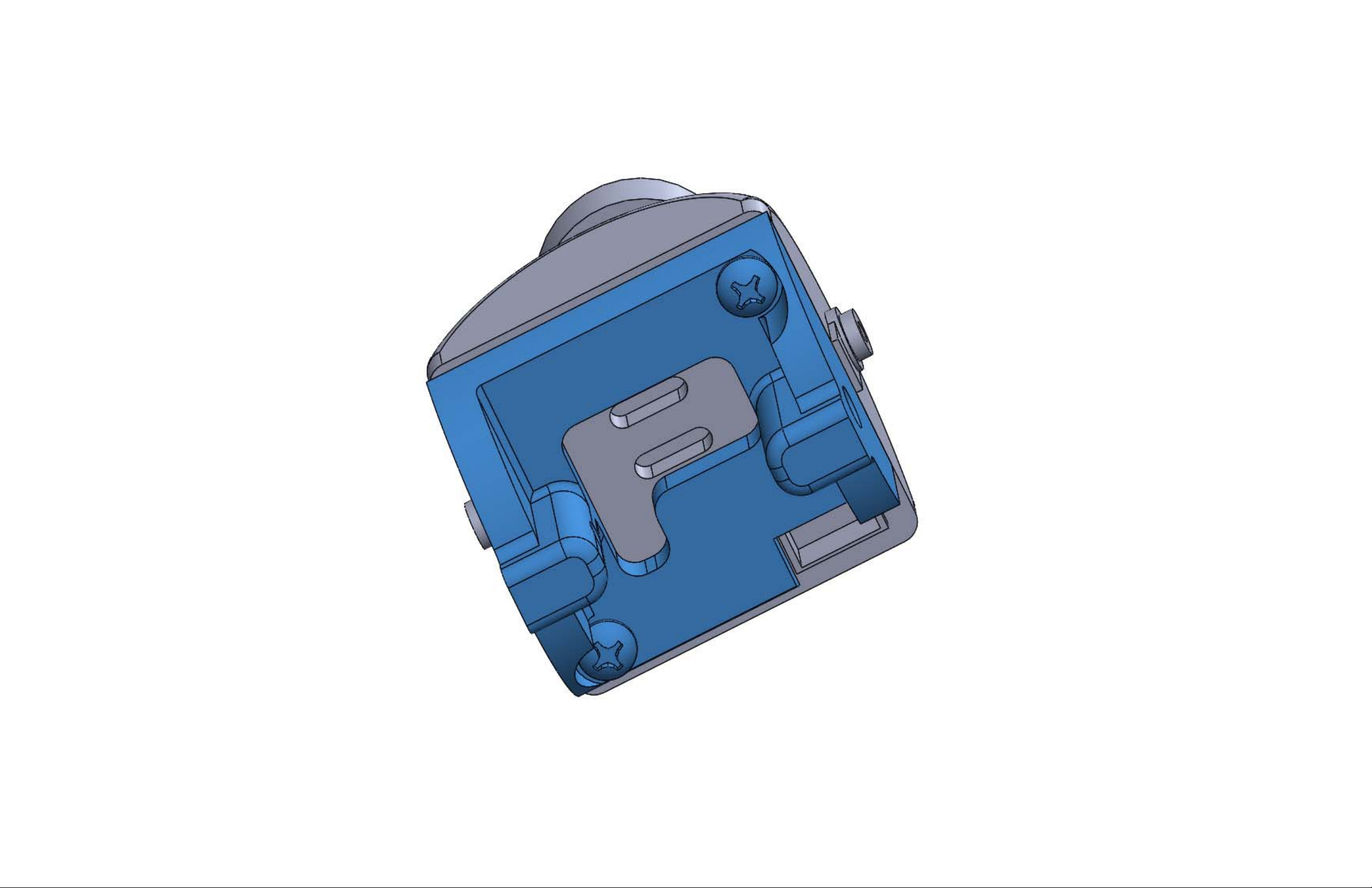
Parts Required:
1 X HS1177 FPV Camera (Sold Separately)
2 X FPV Camera Mount Screws (Phillips head #2 x 3/8” long x stainless steel)
1 X FPV Camera Adjustment Mount (Black 3D Printed ABS Plastic)
Assembly Process:
Remove the 2 existing screws from the back of the camera. Install the Camera Adjustment Mount onto the back of the
camera as shown using the 2 included FPV Camera Mount Screws.
Page 52
Page 53
Page 54

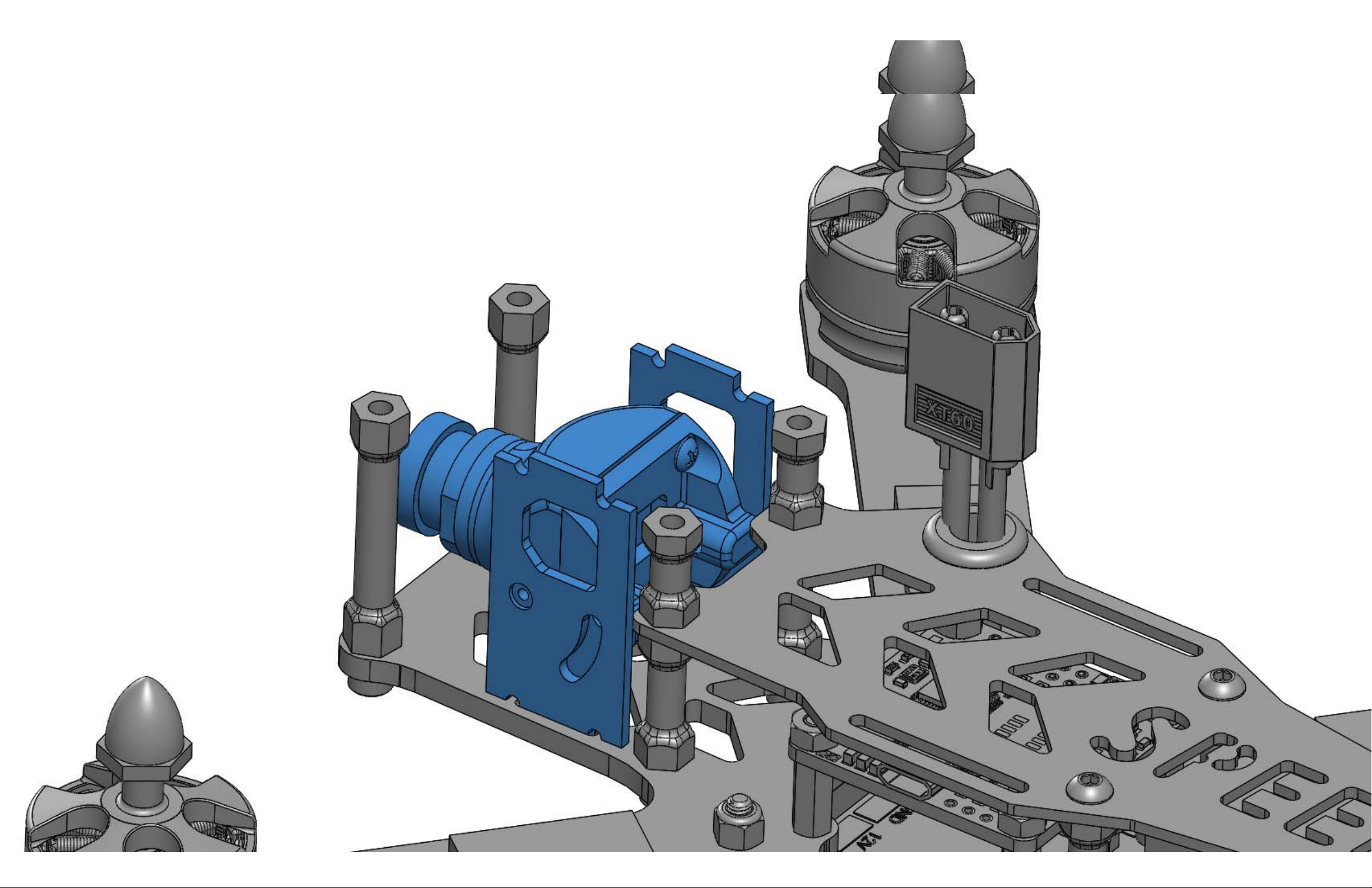
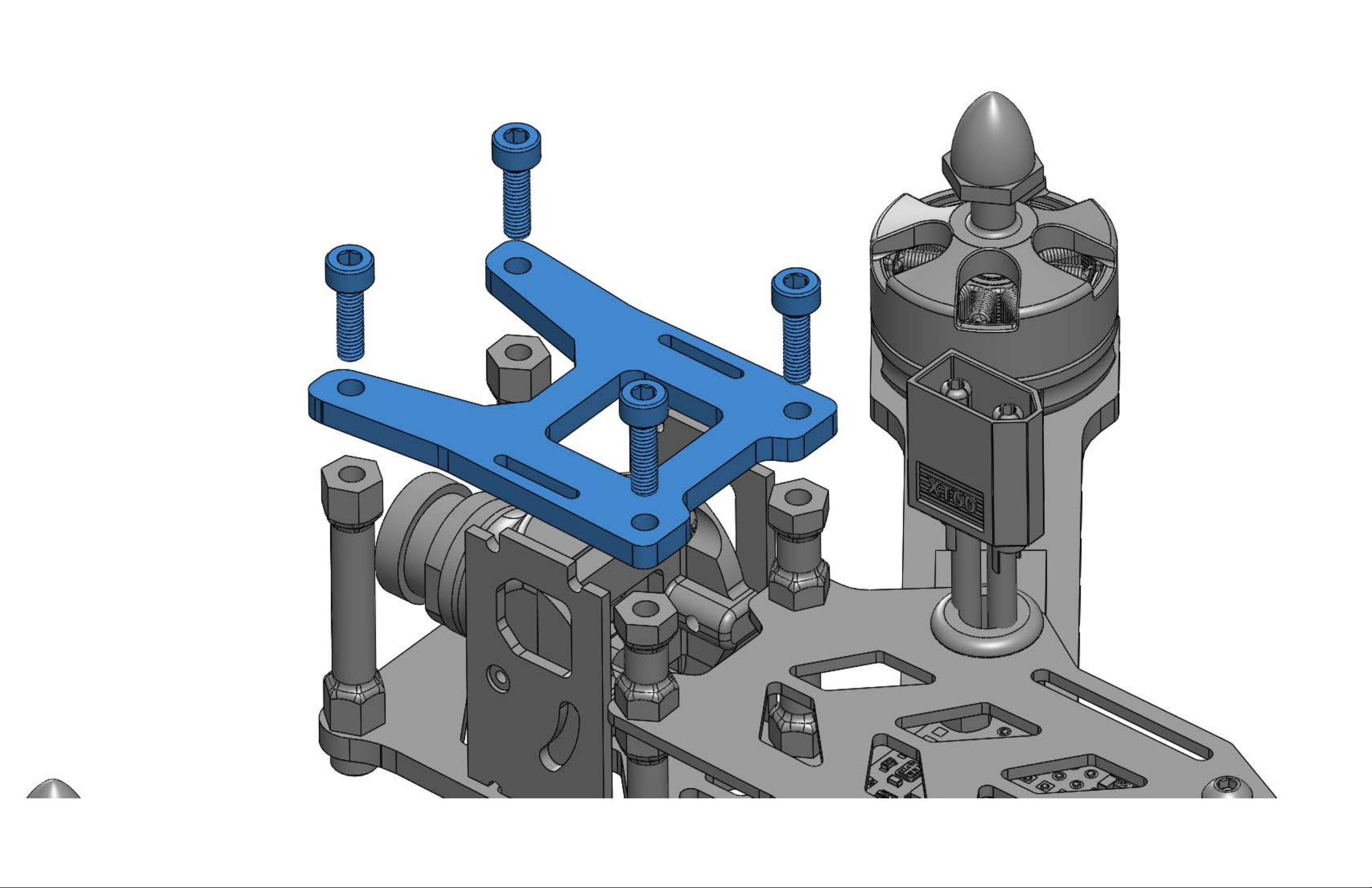
STEP 14
Parts Required:
1 X Assembled HS1177 FPV Camera (from previous step)
2 X FPV Camera Cage, Side Plate (1.5mm CF)
1 X FPV Camera Cage Top Plate (3mm CF)
4 X Socket Head Screw (M3 x 10mm long x blue 7075 aluminum)
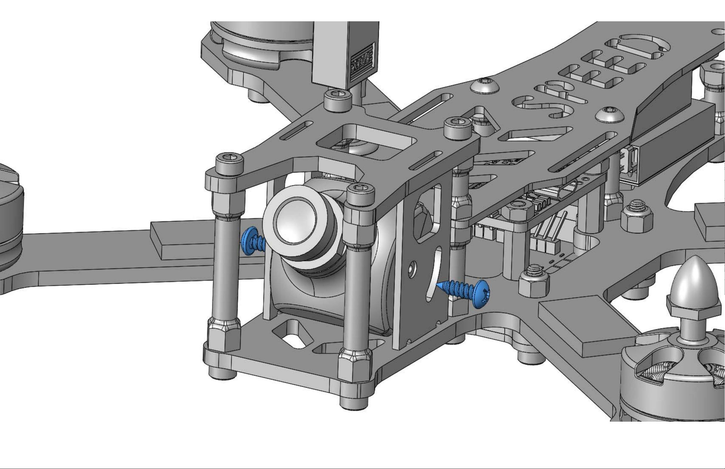
2 X FPV Camera Mount Adjustment Screw (Phillips head #4 x 3/8” long x stainless steel)
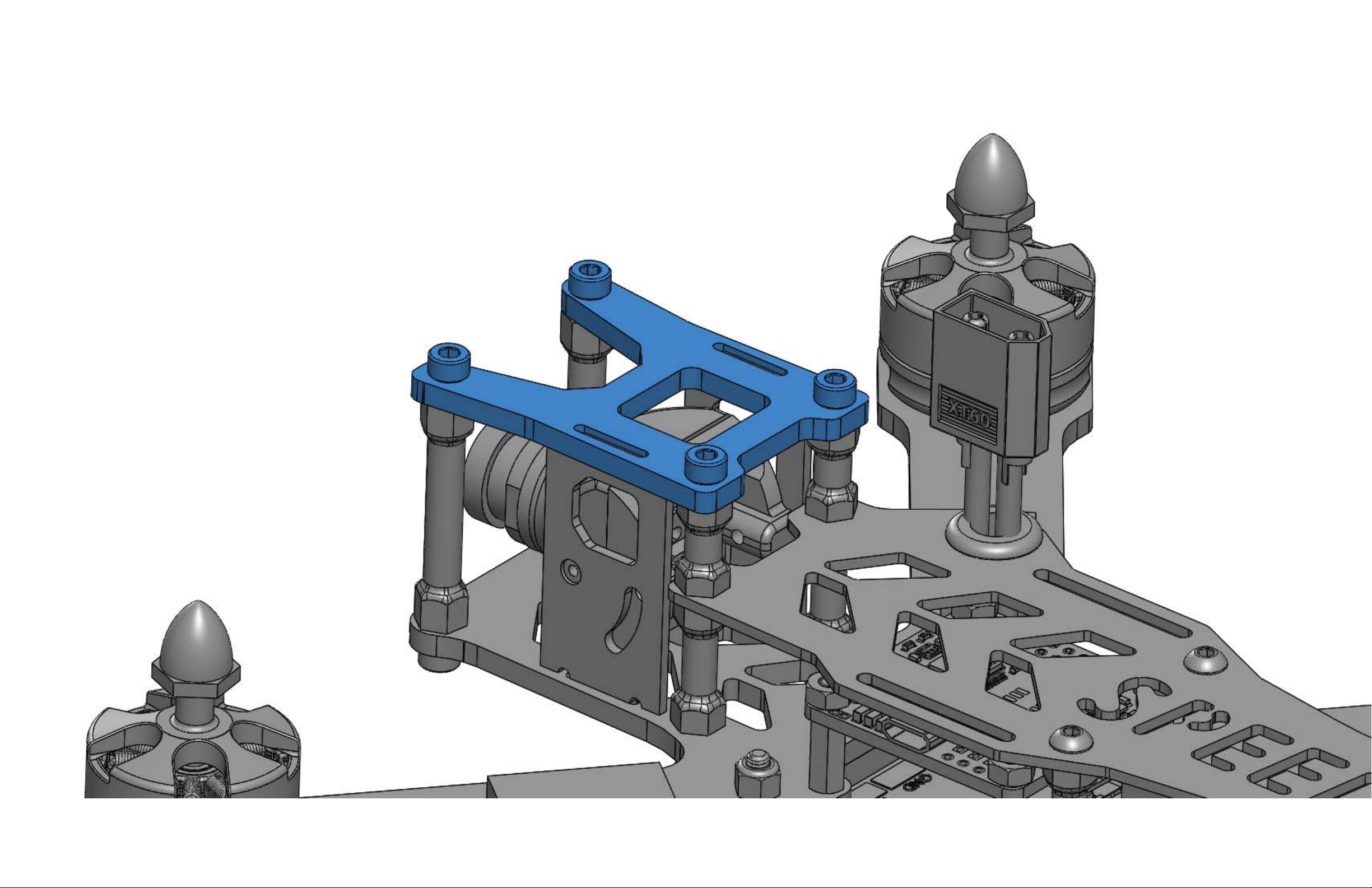
Assembly Process:
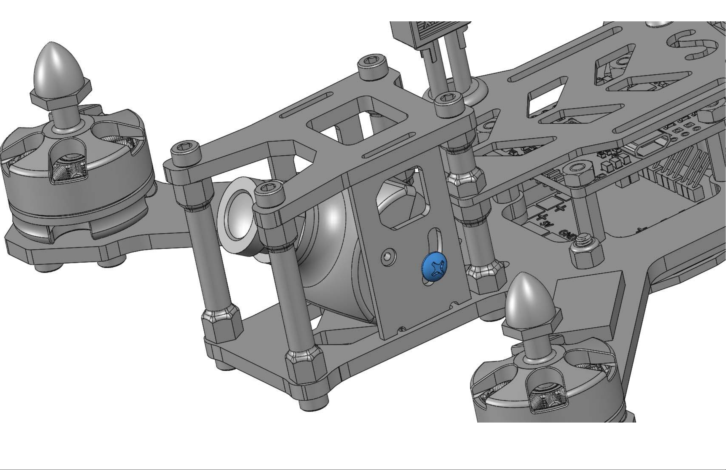
Insert the signal/power wire into the FPV camera. Position the holes in the Camera Cage Side Plates onto the nubs on
the sides of the camera housing. While pressing the assembly together with your hands, feed the Camera Cage Side
Plates down into the slots in the Main Frame Plate. Press the Camera Cage Top Plate in place then install the 4 M3
socket head screws as shown. Set your FPV camera at the desired angle (0° - 45°) then install the 2 Camera Mount
Adjustment Screws. You should not use much torque on these screws!
Only enough to hold the camera in place.
Page 55
Page 56
Page 57
Page 58
Page 59
Page 60

STEP 15
Parts Required:
1 X Antenna Mount (Black 3D Printed TPU)
2 X Antenna Tubes (Blue Plastic 1/8” Diameter)
2 X Antenna Mount Inserts (Silver Aluminum M3 Hole x 4.5mm OD x 5mm long)
2 X Socket Head Screw (M3 x 12mm long x blue 7075 aluminum)
1 X FPV Antenna (Sold Separately)
Assembly Process:
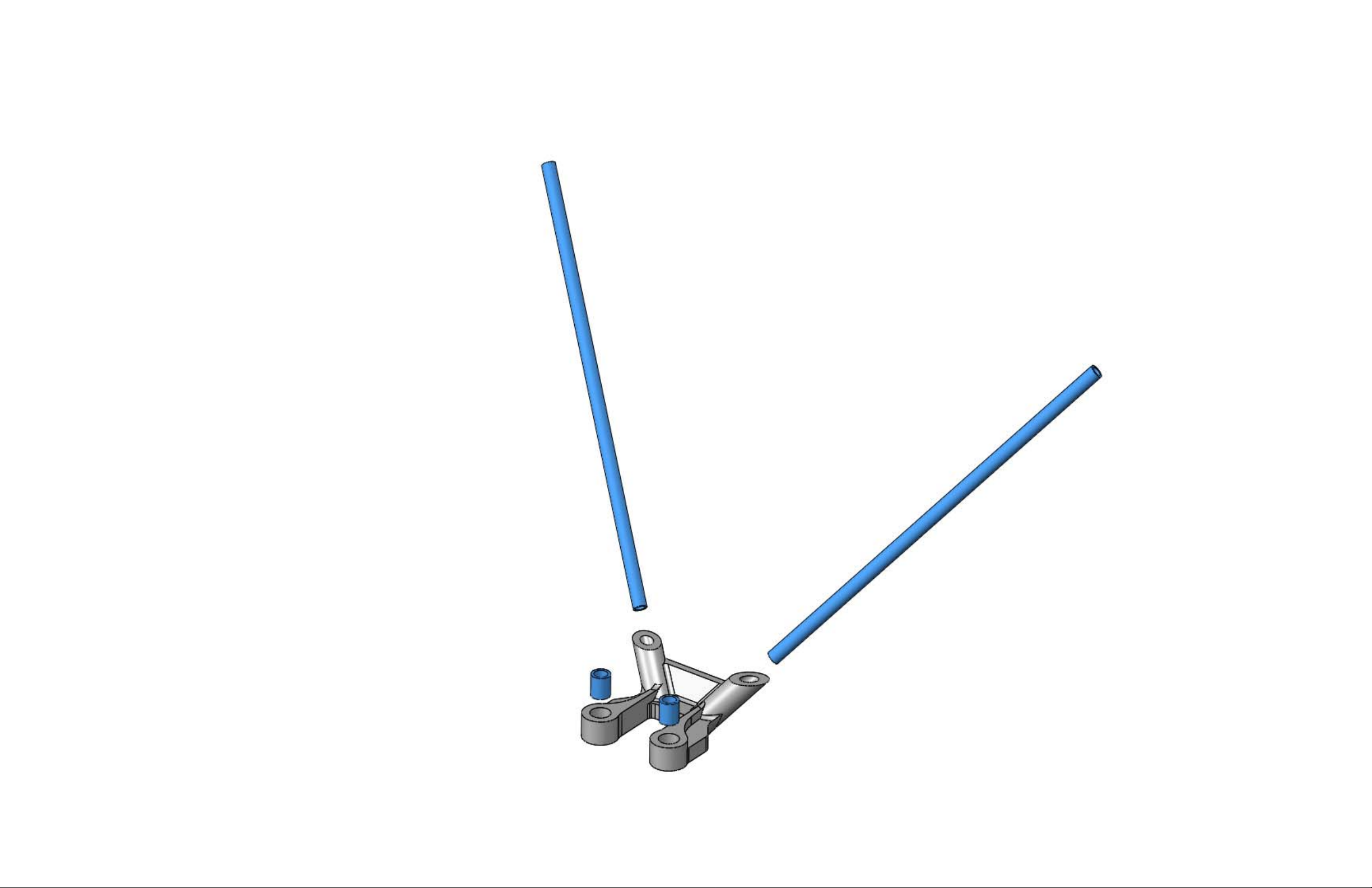
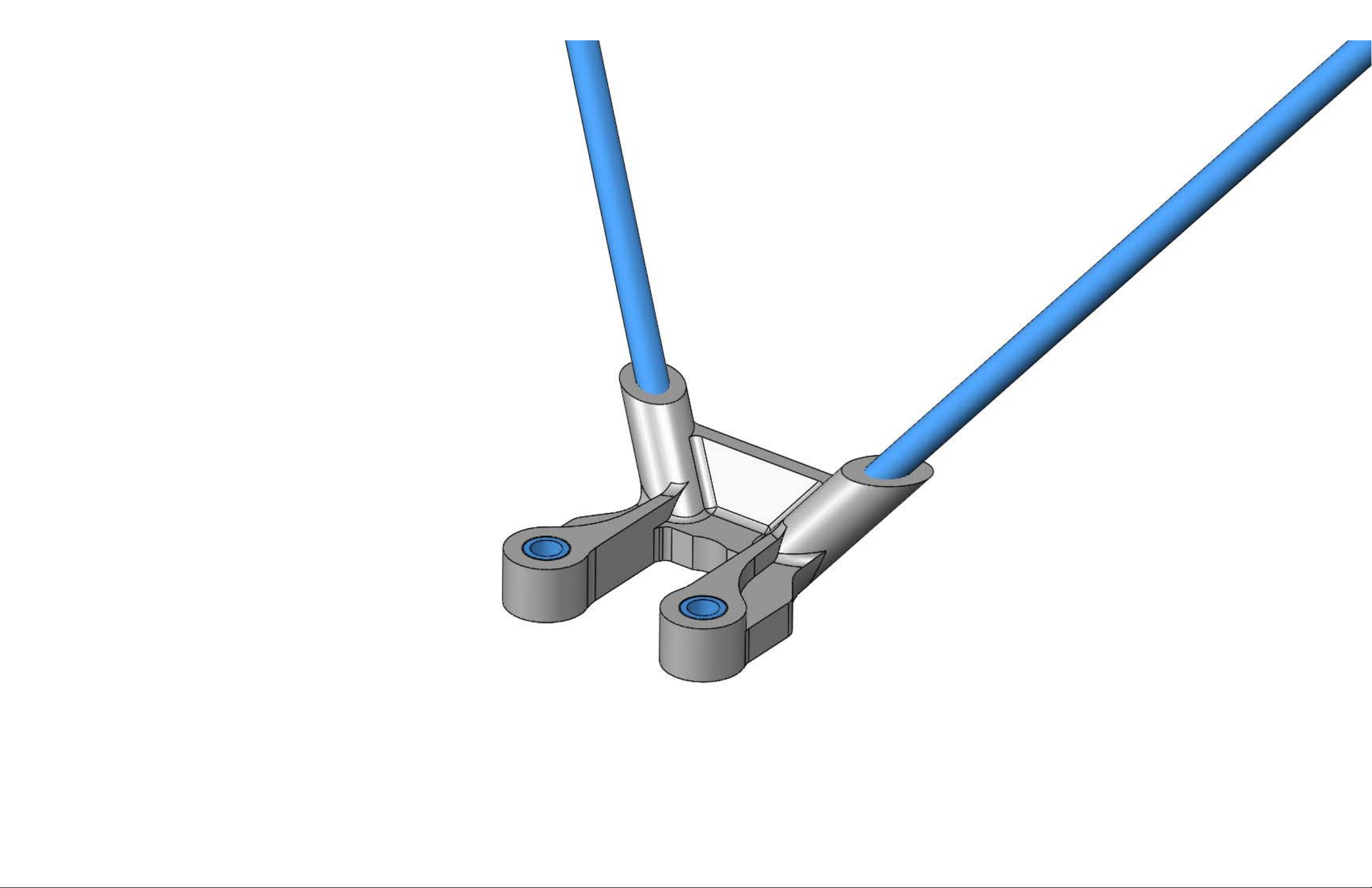
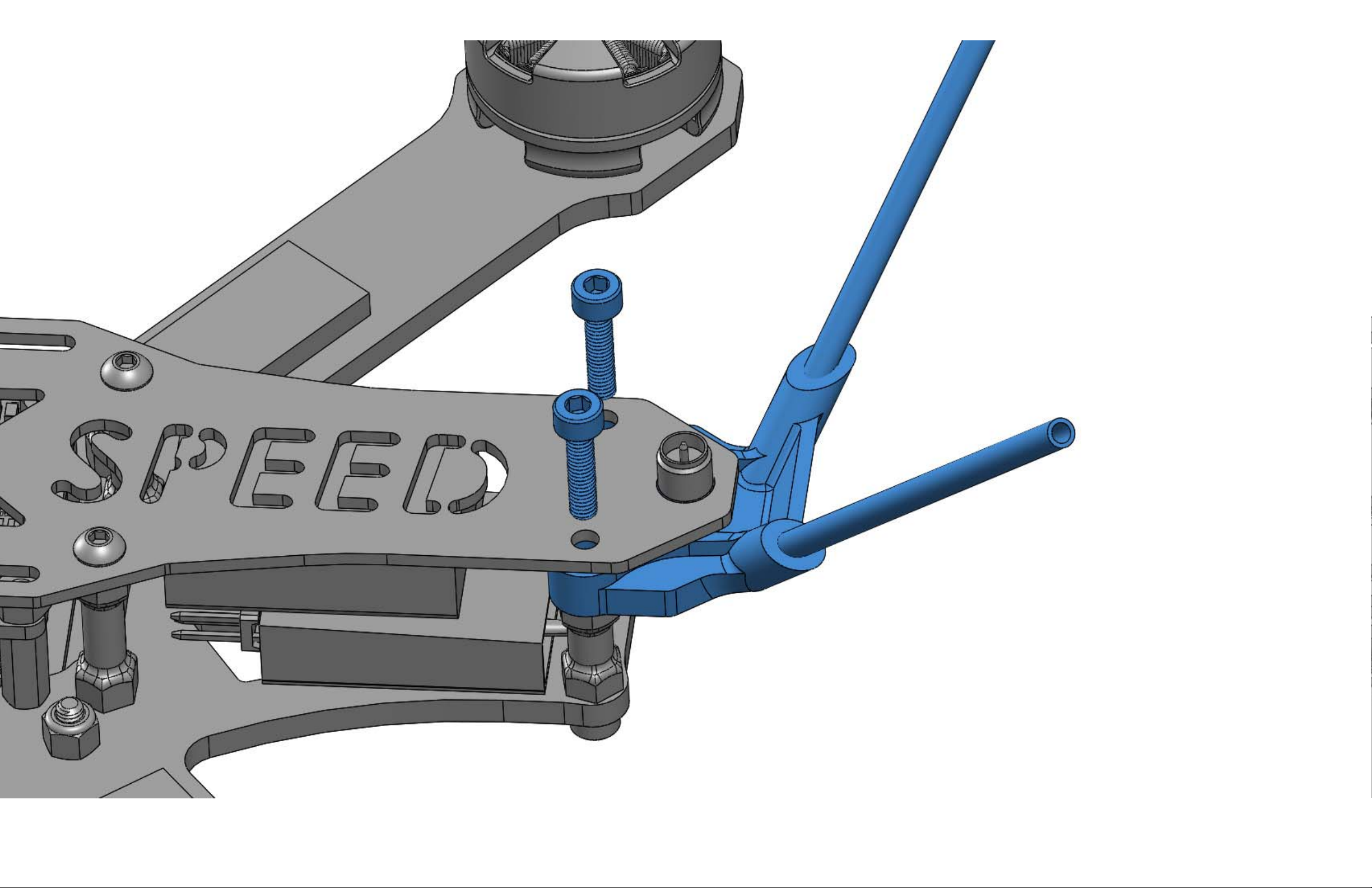
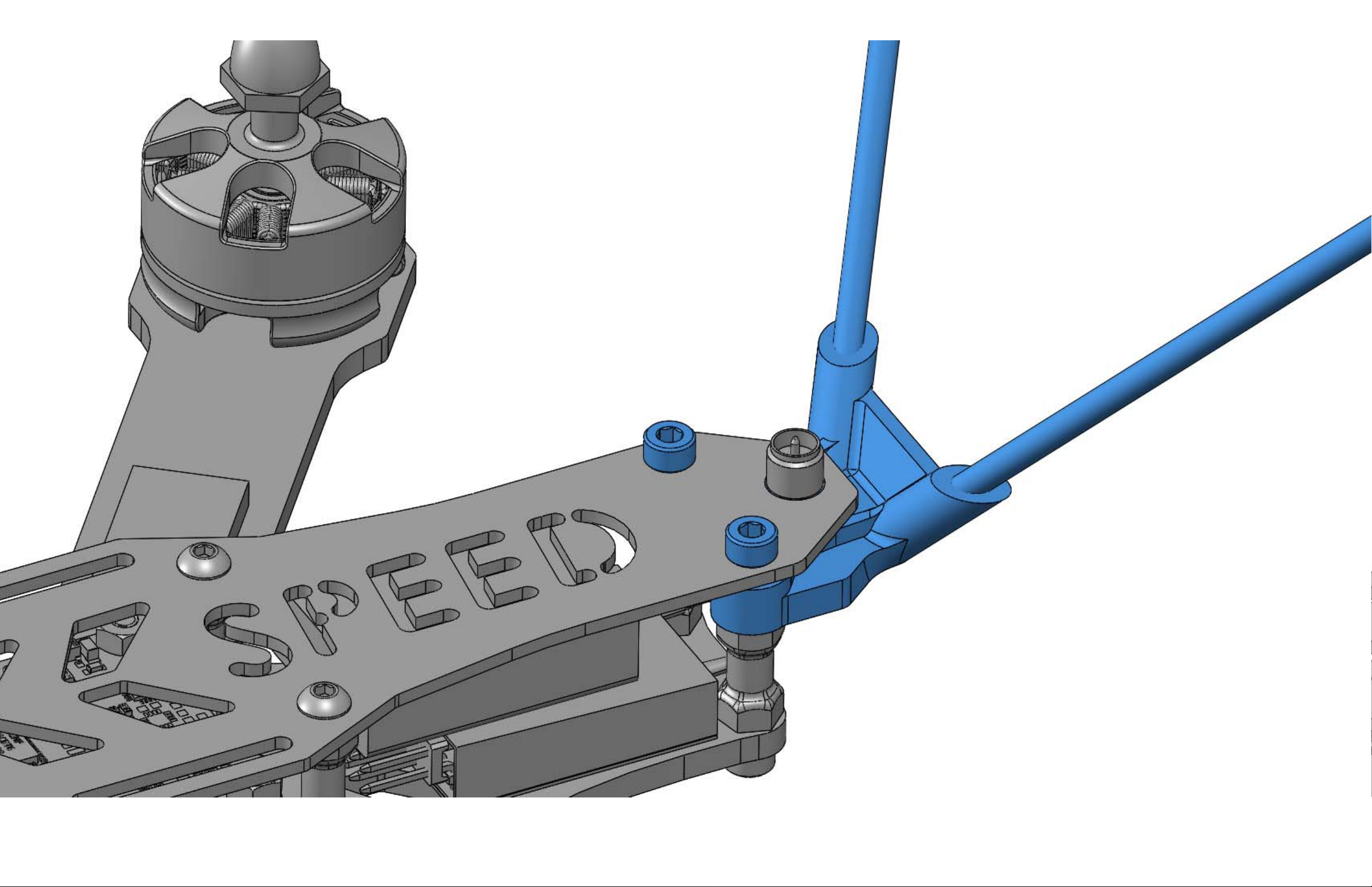
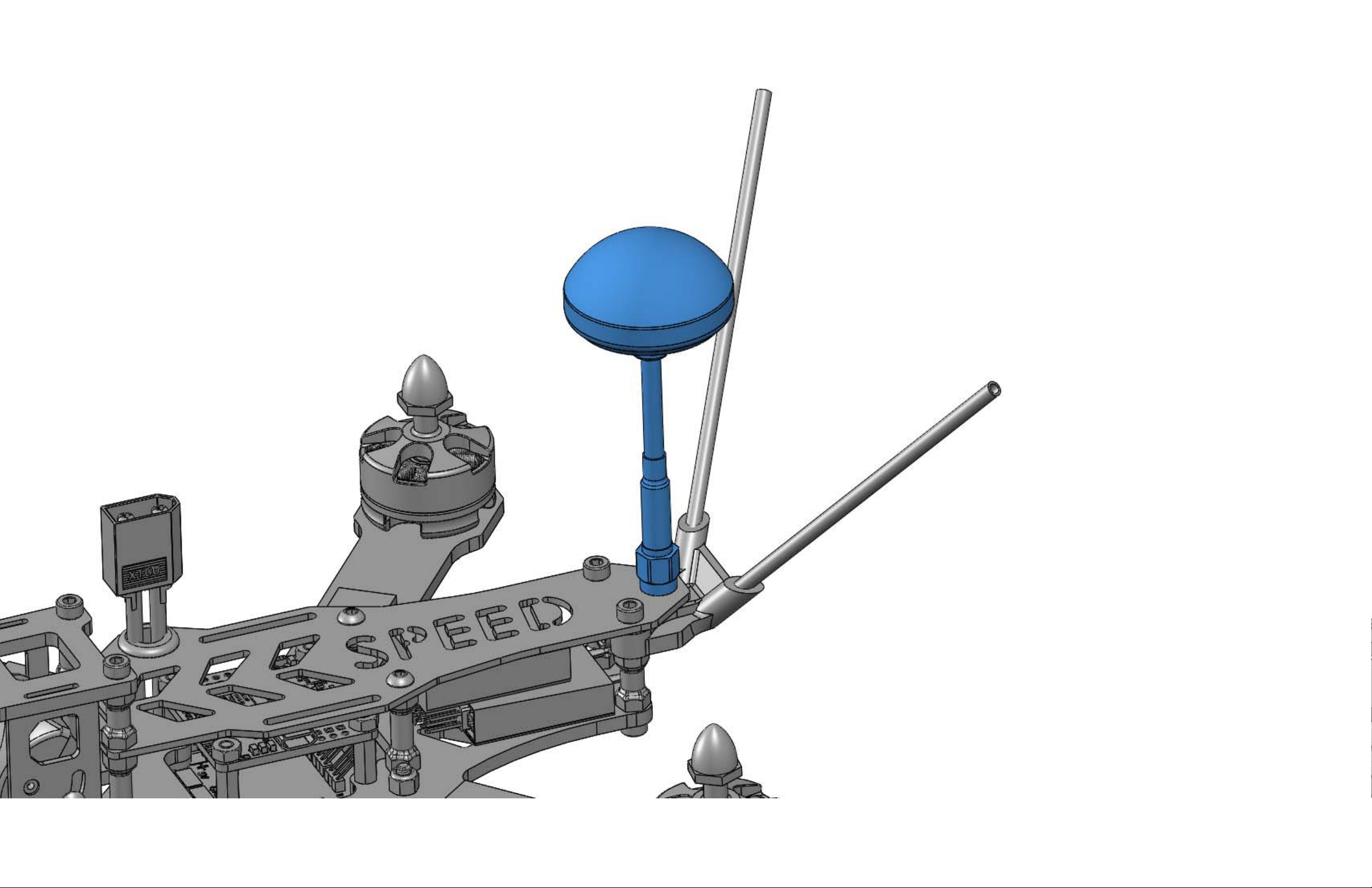
Press the Antenna Tubes into the Antenna Mount as shown. Press in the Antenna Mount Inserts as shown. Feed your
receiver's antenna wires up through the bottom mount holes and install the mount as shown. Use the two Socket Head
Screws to hold the assembly in place. Finally, install your FPV antenna.
Page 61
Page 62
Page 63
Page 64
Page 65
Page 66
SECTION 5
HD CAMERA MOUNT INSTALL
(OPTIONAL)
Page 67

Parts Required:
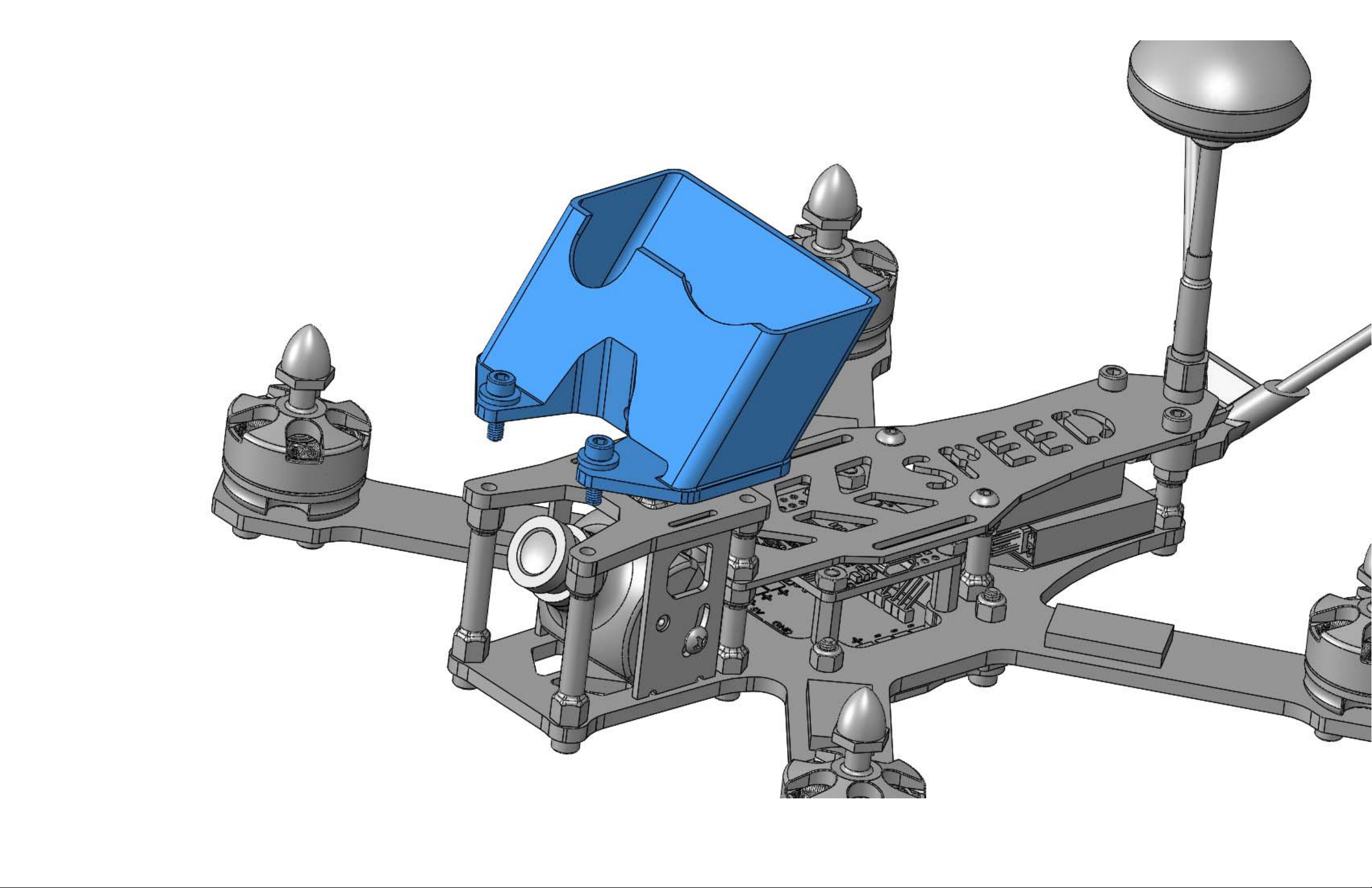
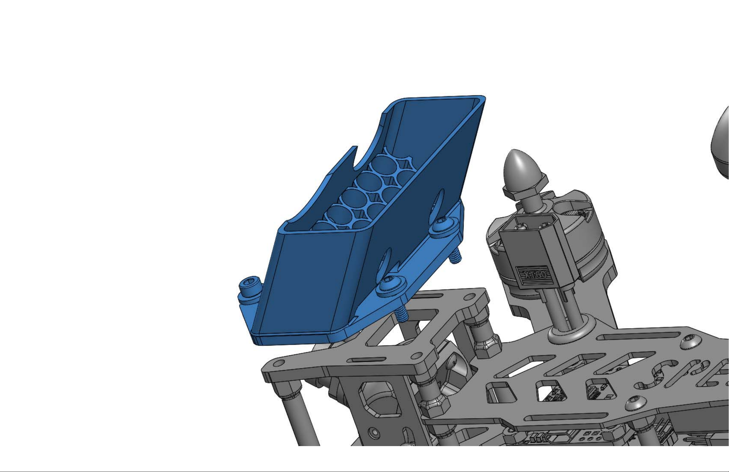
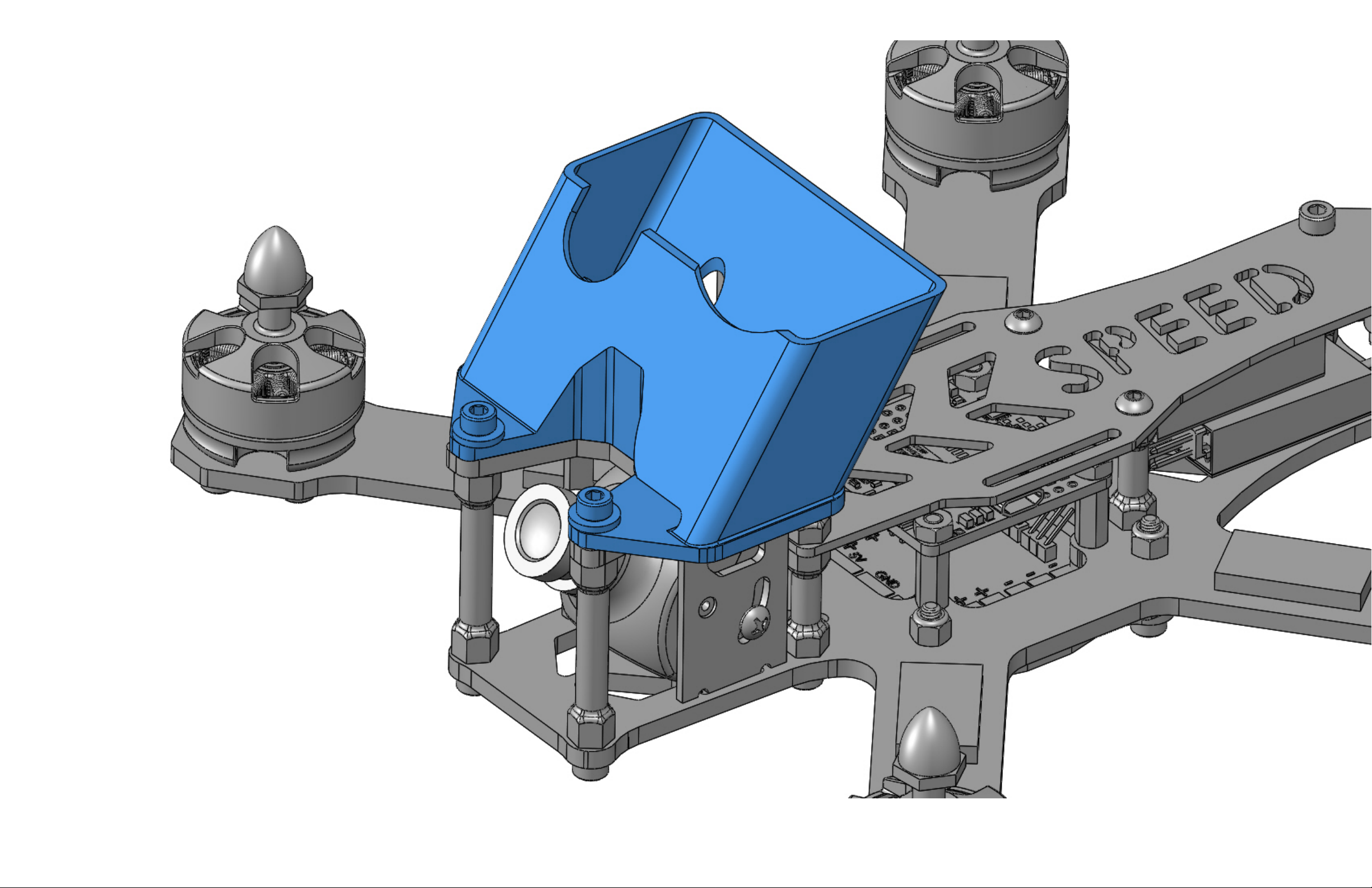
1 X HD Camera Mount (Black 3D Printed TPU)
2 X Button Head Screw (M3 x 10mm long x Steel)
2 X Socket Head Screw (M3 x 10mm long x blue 7075 aluminum)
4 X Washer (M3 x aluminum or steel)
1 X Velcro Strap – Catalyst Machineworks
Assembly Process:
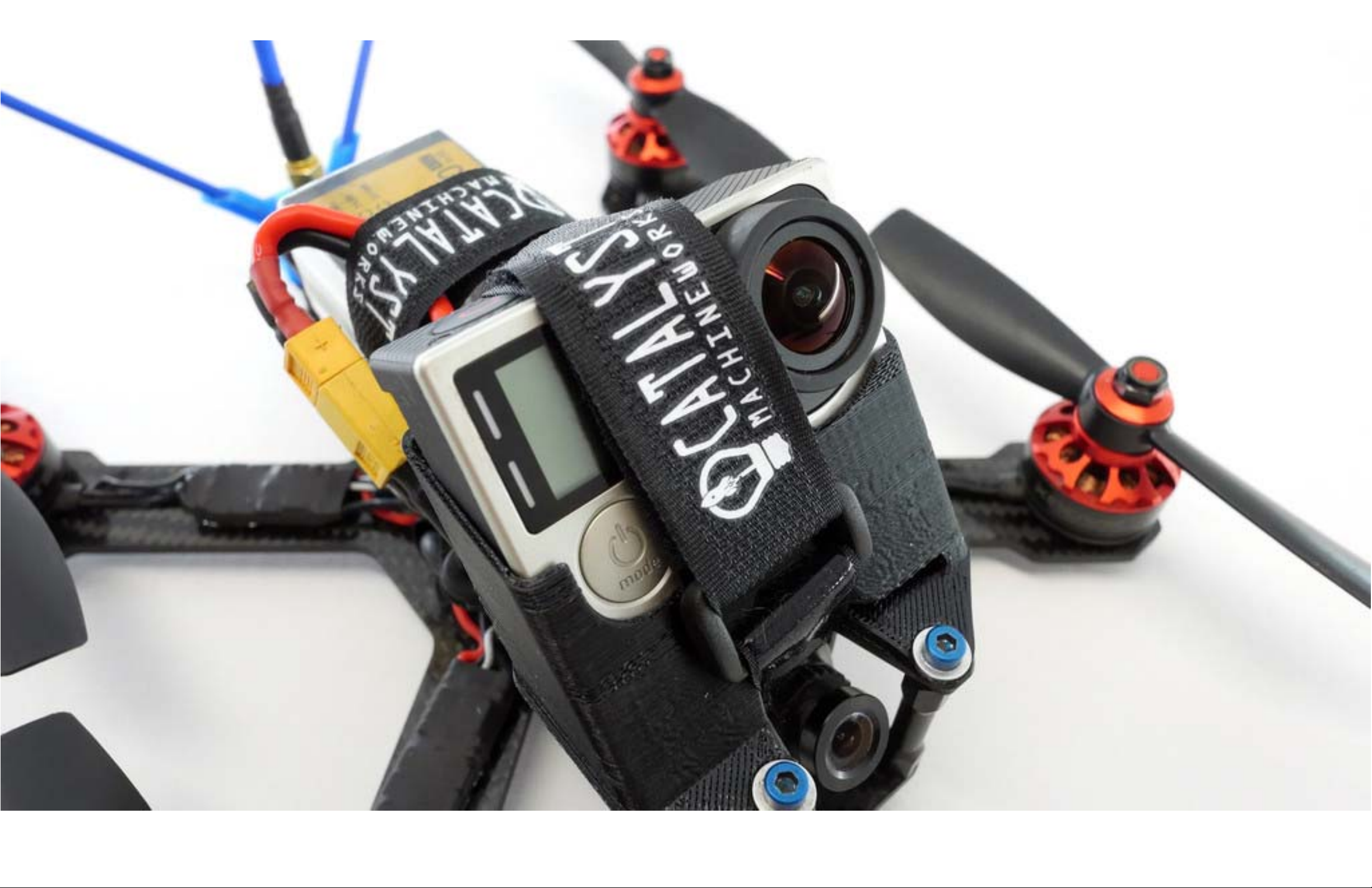
Use the two existing socket head screws located at the front of the FPV camera cage, and the two steel button head
screws (which are included with your camera mount) to fasten the mount down. Use one washer per screw. Install your
camera into the mount then run the Velcro Strap through the slot in the camera cage and around the camera. Make
sure the strap is nice and tight. At 70 MPH your camera might tend to move a bit in flight!
Page 68
Page 69
Page 70
Page 71
Page 72
SECTION 6
LIPO INSTALLATION
Page 73

Lipo Installation:
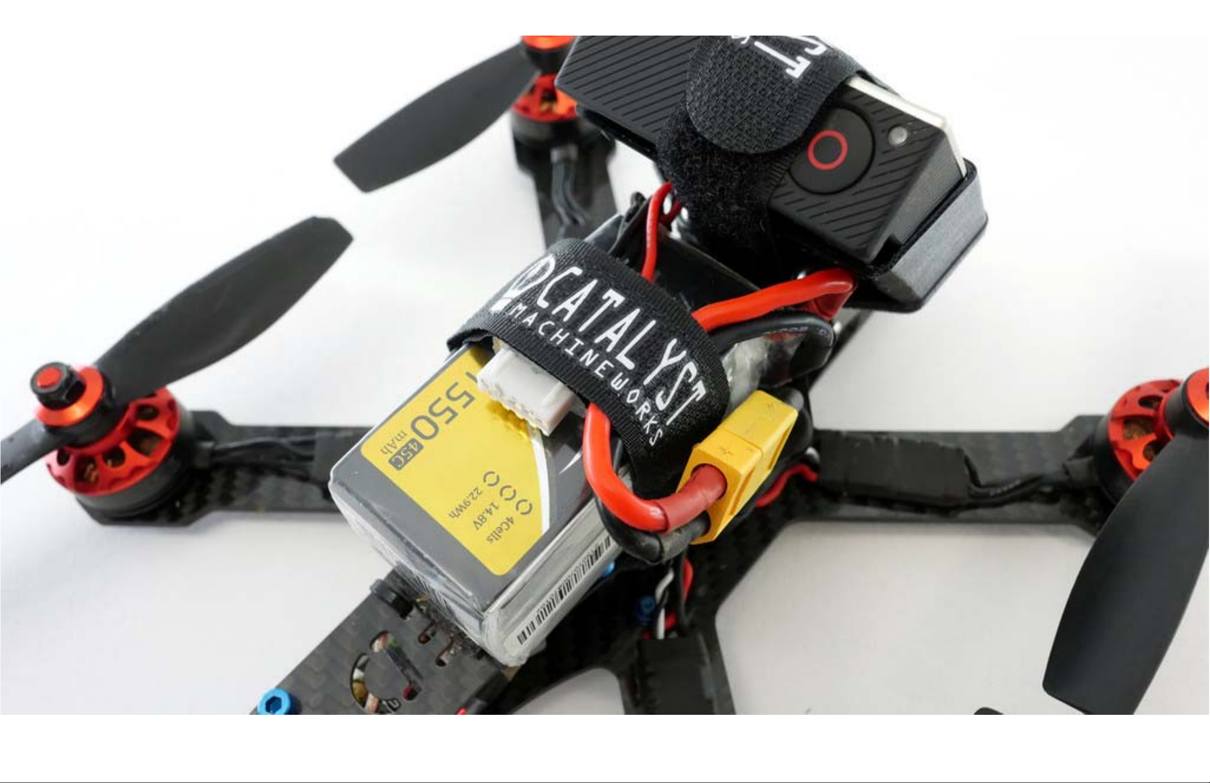
Install a velcro strip along the top of the upper fuselage plate. Install a velcro strip on bottom of your Lipo. If you are
running the 210-R or 180-R without HD camera, mount the lipo as far forward as possible. Check center of gravity after
the lipo is installed and readjust as needed. If you are running the 210-R or 180-R with an HD camera it will be necessary
to mount the Lipo farther back on the fuselage top plate to achieve proper center of gravity. Check center of gravity
after the lipo is installed and readjust as needed. Mount the lip such that it's pigtail wires are facing towards the front of
the craft. Route the pigtail through the velcro strap as shown below. It is VERY important to make sure the lipo is
strapped down tight and positioned exactly between the right and left prop sets. There isn't much space between the
edge of the lipo and the ends of the props. Do not use a lipo that is wider than 35mm.
Page 74
 Loading...