

Page 1
Quick Start Guide
CATALYST 1900 SERIES ETHERNET SWITCHES
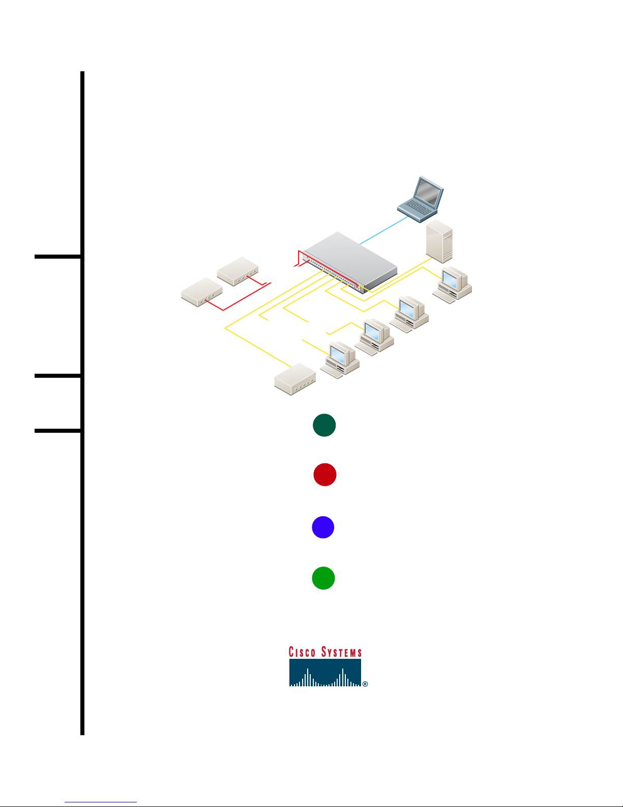
Catalyst 1900
menu-based or
command-line
Serial cable
100BaseT
Switch
interface
100BaseT
Server
10BaseT Hub
10BaseT Router
Crossover
cabling
Straight-through
cabling
SERIES
10BaseT
Workstations
Catalyst 1900
command-line
interface,
web-based,
menu-based,
or SNMP-based
management
station
1
TAKE OUT WHAT YOU NEED
2
CONNECT AND POWER UP THE SWITCH
3
ASSIGN IP INFORMATION AND A PASSWORD TO THE SWITCH
DISPLAY THE CATALYST 1900 SWITCH MANAGER HOME PAGE
4
5
Page 2

Page 3
Take Out What You Need
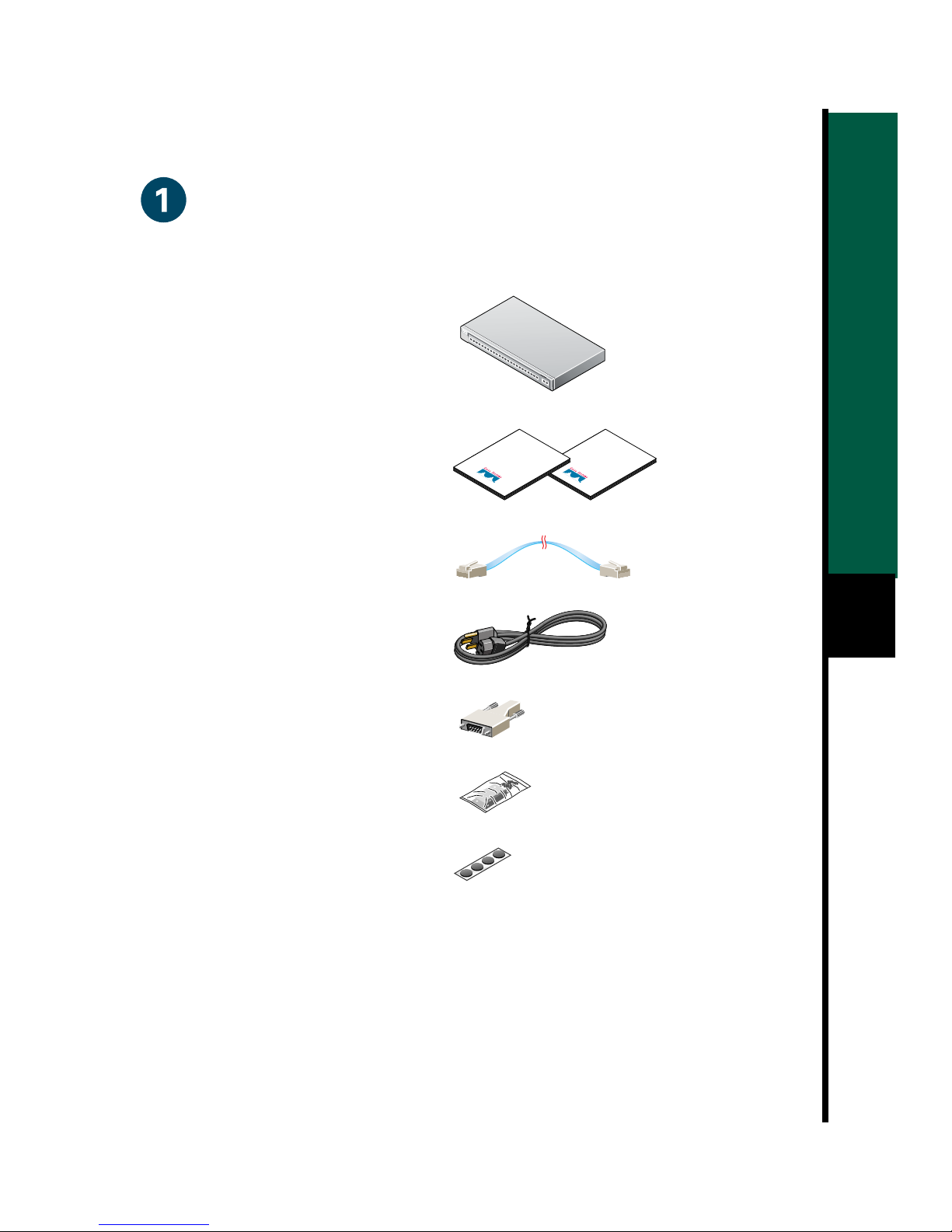
Catalyst 1900 series Ethernet switch
Catalyst 1900 Series Installation and
Configuration Guide and Release Notes
RJ-45-to-RJ-45 rollover console cable
Release
Notes
SERIES
Installation
Configuration
Guide
AC power cable
RJ-45-to-DB-9 serial adapter
Rack-mount kit
Rubber feet
If any item is missing or damaged, contact your Cisco representative or reseller for support.
Note: You need to supply Category 3, 4, or 5 straight-through or crossover cablesto connect
to Ethernet devices.
1
Page 4
Connect and Power Up the Switch
RPS
2x
2x
2x
2x
2x
2x
2x
2x
2x
2x
2x
2x
2x
2x
2x
2x
2x
2x
2x
2x
2x
MODE
2x
SERIES
2x
2x
2x
2x
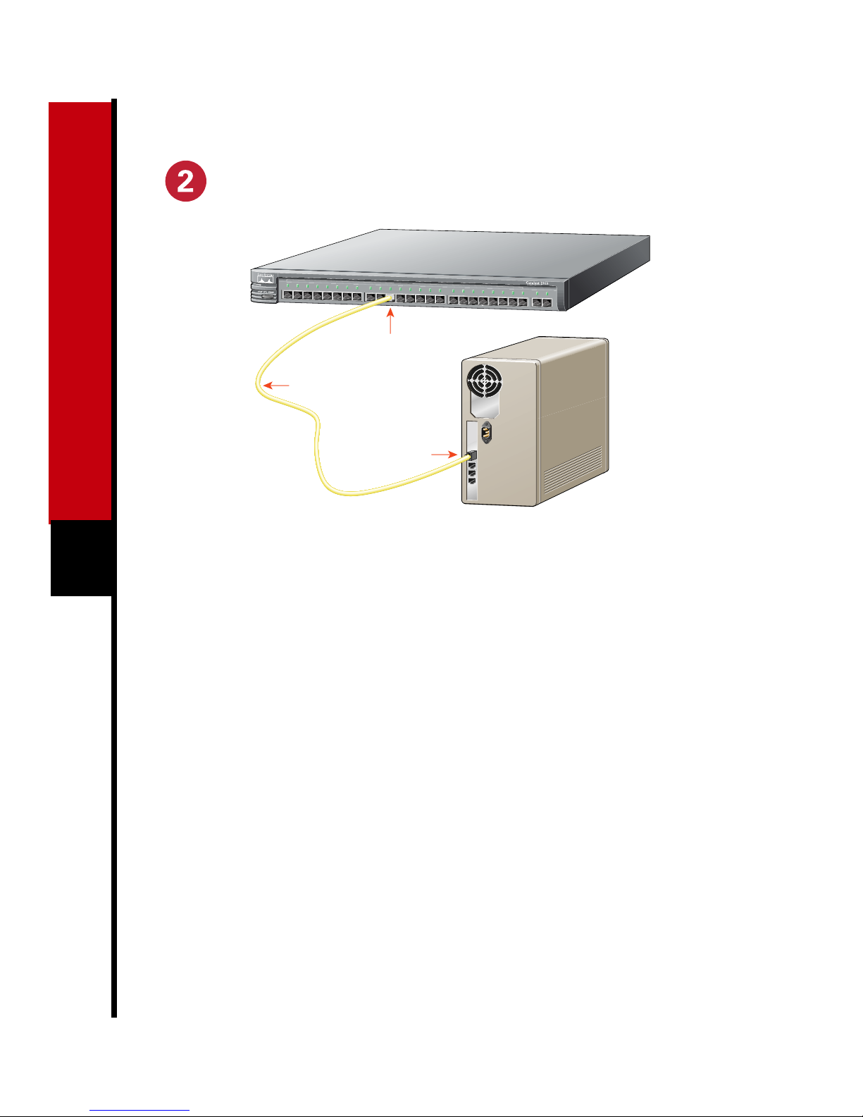
10BaseT port
(RJ-45)
Category 5
straight-through cable
10BaseT port
(RJ-45)
2
Note: Use a straight-through cable to
connect two ports when one of the port
Connect to Other Switches
and Hubs
numbers is designated with an X. Use a
Connect Category 3, 4, or 5 crossover
crossover cable to connect two ports when
bothportnumbersaredesignatedwithanX.
These cables are not supplied.
Connect to Workstations,
Servers, and Routers
Connect a Category 3, 4, or 5
1
straight-through cable to a 10BaseT
port on the switch and to a 10BaseT
port on the workstation, server, or
router.
Connect a Category 5 straight-through
2
cable to a 100BaseTX port on the
switch and to a 100BaseTXport on the
workstation, server, or router.
1
cables between 10BaseT ports on the
switch and on the target switch or hub.
Connect Category 5 crossover cables
2
between100BaseTX portson theswitch
and on the target switch or hub.
For models with one 100BaseFX port,
3
connect a 50/125- or 62.5/125-micron
multimodefiber-opticcable between the
100BaseFX ports on the switch and on
the workstation, server, target switch,
router, or hub. For models with two
fiber-optic ports, use MT-RJ fiber-optic
patch cables ordered from your cable
vendor or from Cisco.
Page 5
100-127V~
200-240V~
RATING
@0.6A
@0.3A
50-60Hz
DC INPUT
FOR REMOTE
POWER SUPPLY
SPECIFIED
IN MANUAL.
+5V @6A
+12V @1A
CONSOLE
AUI
For Catalyst only
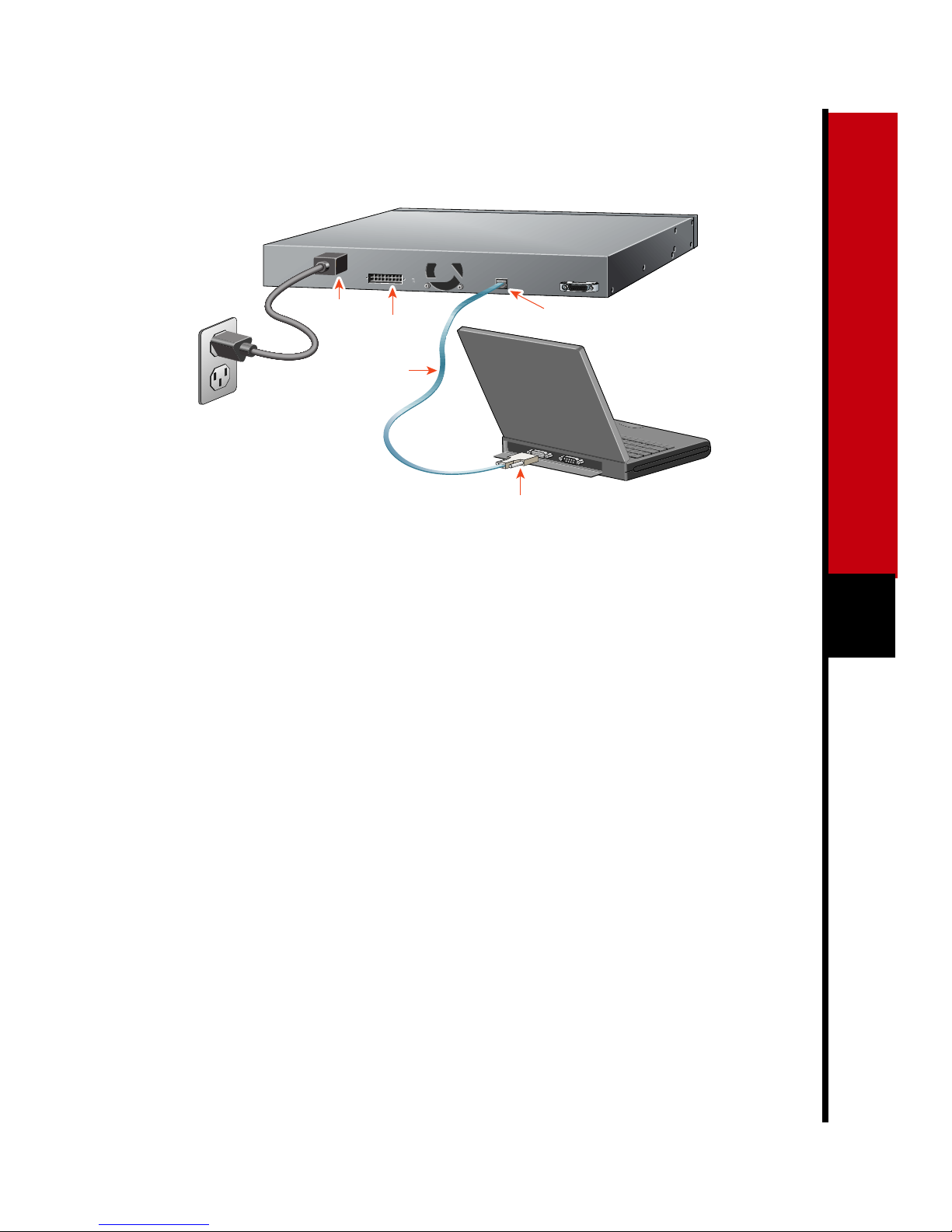
AC power
connector
RJ-45-to-RJ-45
rollover cable
Cisco
RPS
connector
Connect the Console Cable
Before connecting to a terminal, PC, or
1
laptop, make sure its settings match
those of the console port on the switch.
The default settings of the console port
are 9600 baud, 8 data bits, 1 stop bit,
no parity, and no flow control.
Console port
(RJ-45)
RJ-45-to-DB-9 or
RJ-45-to-DB-25 adapter
(labeled Terminal)
From your terminal or PC, start the
4
terminal emulation program.
Power Up the Switch
Connect one end of the power cord to
1
the switch and the other end to an AC
power outlet.
3
Connect the supplied rollover cable to
2
the console port on the switch.
Connect the other end of the console
3
cable to a terminal, PC, or laptop
running terminal emulation software
(such as ProComm or HyperTerminal)
by using an RJ-45 to DB-9 adapter
(supplied) or, if necessary, an RJ-45 to
DB-25 adapter (not supplied).
Note: If you are connecting to a Cisco
600W AC redundant power system (RPS),
refertothe Catalyst 1900 Series Installation
andConfiguration Guide and the latest RPS
documentation for more information.
Wait approximately 2 minutes for the
2
switchto complete itspower-onself-test
(POST) and to discover the network.
Page 6

Assign IP Information and a Password to the
Switch
You assign an IP address to the switch so
that you can use the switch management
interfaces and so that the switch can
communicate with local routers and the
Internet. Assigning a password provides
security against unauthorized access to the
options available from the management
interfaces and is required for using the
Catalyst 1900 Switch Manager.
Note: If the switch will be a cluster
member, it is not always necessary to assign
IP information ora password, as the switch
will be accessed and managed through the
password and IP address of the command
4
switch. Refer to the Catalyst 1900 Series
Installation and Configuration Guide for
more information.
Assign IP Information
Catalyst 1900 Management Console
Copyright (c) Cisco Systems, Inc. 1993-1999
All rights reserved.
Standard Edition Software
Ethernet address: 00-E0-1E-7E-B4-40
PCA Number: 73-2239-01
PCA Serial Number: SAD01200001
Model Number: WS-C1924-A
System Serial Number: FAA01200001
---------------------------------------
User Interface Menu
[M] Menus
[I] IP Configuration
[P] Console Password
Enter Selection: I
The IP Configuration Menu appears.
Enter the [I] IP address option from the
2
IP Configuration Menu.
Catalyst 1900 - IP Configuration
Contact your system administrator for the
switch IP information, and record it here.
Switch IP address:
Subnet mask:
Default gateway:
After POST completes, the
1
Management Console Logon Screen
appears on your terminal, PC, or
laptop. Enter the [I] IP Configuration
option from this logon screen.
Ethernet Address: 00-E0-1E-7E-B4-40
-------------Settings-----------------[I] IP address
[S] Subnet mask
[G] Default gateway
[B] Management Bridge Group
[M] IP address of DNS server 1
[N] IP address of DNS server 2
[D] Domain name
[R] Use Routing Information Protocol
-------------Actions------------------[P] Ping
[C] Clear cached DNS entries
[X] Exit to previous menu
Enter Selection: I
Page 7

The following prompt appears:
3
Enter administrative IP address in
dotted quad format (nnn.nnn.nnn.nnn):
Current setting ===> 0.0.0.0
New setting ===>
If the switch does not have an IP
address, the Current setting appears as
0.0.0.0, and you can enter the IP
addressof the switch astheNew setting.
If the switch is connected to a network
that has a DynamicHost Configuration
Protocol (DHCP)/Bootstrap Protocol
(BOOTP) server, the server might
automatically assign an IP address.
If you plan to assigna subnet mask and
4
default gateway, use the [S] Subnet
mask and [G] Default gateway options
from the IP Configuration Menu.
Assign a Password
From the IP Configuration Menu,enter
1
the [X] Exit option to again display the
Management Console Logon Screen.
---------------------------------------
User Interface Menu
[M] Menus
[I] IP Configuration
[P] Console Password
Enter the [P] Console Password option
2
from this screen. Enter a 4- to
8-character password, and verify as
prompted. This password is an
unencrypted privileged password that
controls switch access.
Press any key to return to the
3
Management Console Logon Screen.
The switch is designed to operate with little
or no user intervention. In most cases, you
can use itwith its default settings assoon as
you assign it an IP address and password.
To change the switch configuration and to
monitor network conditions and statistics,
you can use the managementconsole menus
or use the web-based Catalyst 1900 Switch
Manager from anywhere on your intranet.
If the switch is running the Cisco Catalyst
1900/2820EnterpriseEditionSoftware, you
can also use the command-line interface
(CLI).
The following section describes how to
access the Catalyst 1900 Switch Manager
homepage.Forinformationaboutusingthe
management console menus or the Catalyst
1900 Switch Manager, refer to the Catalyst
1900 Series Installation and Configuration
Guide.For information about the CLI, refer
to the on-line Catalyst 1900 Series and
Catalyst 2820 Series Command Reference.
5
Page 8

Display the Catalyst 1900 Switch Manager
Home Page
After you assign an IP address and password to the switch, you can display the Catalyst 1900
Switch Manager.The Switch Manager supports thefollowing platforms andnetwork browsers:
Minimum Operating System
Operating System
Windows 95 Service Pack 1 4.5, 4.51, or 4.61 4.01a or 5.0
Windows 98 Second Edition 4.5, 4.51, or 4.61 4.01a or 5.0
Windows NT 4.0 Service Pack 3 4.5, 4.51, or 4.61 4.01a or 5.0
Solaris 2.5.1
or higher
Note: Netscape Communicator version 4.60 is not supported.
To display the Switch Manager home page, start Netscape Communicator or Microsoft
Internet Explorer, and configure the browser options needed to communicate with the switch
Requirements
SUN-recommended patch
cluster for the OS and Motif
library patch 103461-24
Netscape
Communicator
4.5, 4.51, or 4.61 Not supported
Microsoft Internet
Explorer
6
Configuring Netscape
Communicator (All Versions)
From the menu bar, select
1
Edit>Preferences.
In the Preferences window, click
2
Advanced.
Select the Enable Java, Enable
3
JavaScript, and Enable Style Sheets
check boxes.
From the Advanced drop-down list,
4
click Cache.
Click the Every time radio button.
5
Click OK.
6
Configuring Microsoft
Internet Explorer 4.01a
Note: For procedures on how to configure
Microsoft Internet Explorer 5.0, refer tothe
Catalyst 1900 Series Installation and
Configuration Guide.
From the menu bar, select
1
View>Internet Options.
In the Internet Options window, select
2
the Advanced tab.
Scroll through the list of optionsto Java
3
VM, select the Java JIT compiler
enabled and Java logging enabledcheck
boxes. Click Apply.
Page 9

In the Internet Options window, select
4
the General tab.
In the Security Settings window, click
13
OK.
In the Temporary Internet Files section,
5
click Settings.
In the Settings window, click the Every
6
visit to the page radio button, and click
OK.
In the Internet Options window, select
7
the Security tab.
In the Zone drop-down list, select
8
Trusted Sites Zone, and click Custom.
Click Settings....
9
In the Security Settings window, scroll
10
to the Java>Java permissions section,
and select the Custom radio button.
Click Java Custom Settings..., which
11
appears at the bottom of the window.
Inthe TrustedSites Zone window,select
12
the Edit Permissions tab.
In the Internet Options window,
14
select the Security tab,and verify that
the Zone drop-down list is set to
Trusted Sites Zone.
In the Trusted Sites Zone section,
15
click Add Sites....
In the Trusted Sites Zone window,
16
deselect the Require server
verification check box.
In the Add this Web site to the Zone
17
field, enter the IP address of the
switch.
Note: Iftheswitch will be a member of a
cluster, youonly need toenter theaddress
of the cluster command switch. Refer to
the documentation for the cluster
command switch for more information.
Click Add, and then click OK.
18
7
(a) If the buttons under Run Unsigned
Content are not available,return to
the Security Settings window, and
select either Medium or Low safety
in the Reset Java Permissions list
box. Click Reset.
(b) Under Run Unsigned Content,
select the Enable radio button, and
click OK.
In the Internet Optionswindow,click
19
OK.
Page 10
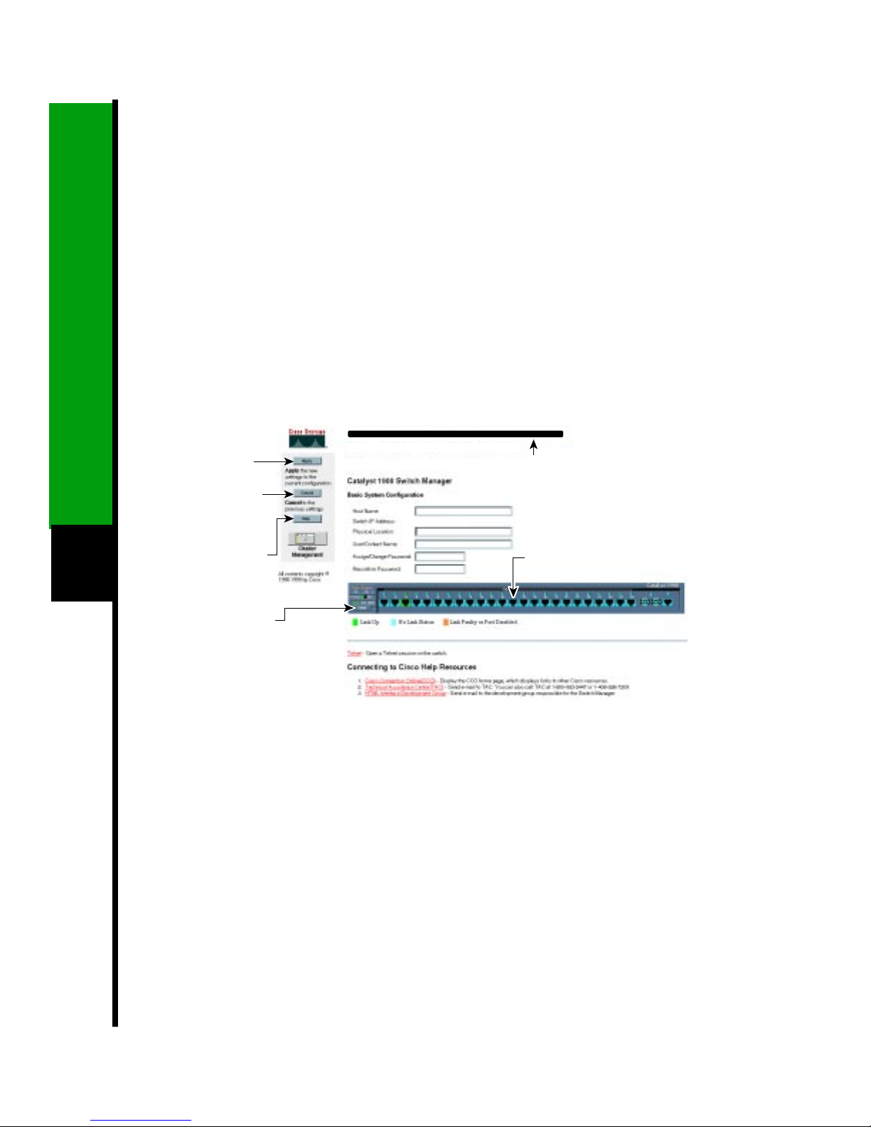
Display the Switch Manager Home Page
When the browser is configured, display the Catalyst 1900 Switch Manager home page as
follows:
Enter the IP address of the switch in the Location field if you are using Netscape
1
Communicator(theAddressfieldif you are using Microsoft Internet Explorer), and press
Return.
Enter the switchpassword assigned through the console menu (see “Assigna Password”
2
in the previous section). At the prompt, click OK.
The Catalyst 1900 Switch Manager home page is displayed.
Click Apply
to save the
changes
you made.
Click Cancel
to discard all
unsaved
changes.
8
Click Help for
procedures and
detailed field
descriptions.
Click the Mode
button to change
the mode the port
LEDs display.
HOME PORT ADDRESS CGMPSNMP STP CDP SPAN CONSOLE STATISTICS SYSTEM
Click these topics to move from
page to page. On Netscape
Communicator only, when the
cursor is above a topic, a pop-up
10.1.126.45
briefly describes the options
on that page.
Click a port to display its
settings, status, and statistics.
You can use the Switch Manager to change the switch configuration and to monitor switch
conditions and statistics from anywhere on your intranet.
Refer to the Catalyst 1900 Series Installation and Configuration Guide for complete
information about the Catalyst 1900 Switch Manager and how to configure the switch.
Page 11

9
Page 12

Corporate Headquarters
Cisco Systems, Inc.
170 West Tasman Drive
San Jose, CA 95134-1706
USA
http://www.cisco.com
Tel: 408 526-4000
800 553-NETS (6387)
Fax: 408 526-4100
European Headquarters
Cisco Systems Europe s.a.r.l.
Parc Evolic, Batiment L1/L2
16 Avenue du Quebec
Villebon, BP 706
91961 Courtaboeuf Cedex
France
http://www-europe.cisco.com
Tel: 33 1 69 18 61 00
Fax: 33 1 69 28 83 26
Americas
Headquarters
Cisco Systems, Inc.
170 West Tasman Drive
San Jose, CA 95134-1706
USA
http://www.cisco.com
Tel: 408 526-7660
Fax: 408 527-0883
Asia Headquarters
Nihon Cisco Systems K.K.
Fuji Building, 9th Floor
3-2-3 Marunouchi
Chiyoda-ku, Tokyo 100
Japan
http://www.cisco.com
Tel: 81 3 5219 6250
Fax: 81 3 5219 6001
Cisco Systems has more than 200 offices in the following countries. Addresses, phone numbers, and fax numbers are listed on the
Cisco Connection Online Web site at http://www.cisco.com/offices.
Argentina • Australia • Austria • Belgium • Brazil • Canada • Chile • China • Colombia • Costa Rica • Croatia • Czech Republic • Denmark • Dubai, UAE
Finland • France • Germany • Greece • Hong Kong • Hungary • India • Indonesia • Ireland • Israel • Italy • Japan • Korea • Luxembourg • Malaysia
Mexico • The Netherlands • New Zealand • Norway • Peru • Philippines • Poland • Portugal • Puerto Rico • Romania • Russia • Saudi Arabia • Singapore
Slovakia • Slovenia • South Africa • Spain • Sweden • Switzerland • Taiwan • Thailand • Turkey • Ukraine • United Kingdom • United States •
Copyright © 1999, Cisco Systems, Inc. All rights reserved. Access Registrar,AccessPath, Any to Any, AtmDirector, CCDA, CCDE, CCDP, CCIE, CCNA, CCNP,CCSI, CD-PAC, the
Cisco logo, Cisco Certified Internetwork Expert logo, CiscoLink, the Cisco Management Connection logo, the Cisco NetWorks logo, the Cisco Powered Network logo, Cisco Systems
Capital, the Cisco Systems Capital logo, Cisco Systems Networking Academy, the Cisco Systems Networking Academy logo, the Cisco Technologies logo, ConnectWay, Fast Step,
FireRunner, GigaStack, IGX, Internet Quotient, Kernel Proxy, MGX, Natural Network Viewer, NetSonar, Network Registrar, Packet, PIX, Point and Click Internetworking, Policy
Builder,Precept, Secure Script, ServiceWay, SlideCast, SMARTnet, The Cell, TrafficDirector,TransPath,ViewRunner, VisionWay, VlanDirector, Workgroup Director,and Workgroup
Stack are trademarks; Changing the Way We Work, Live, Play, and Learn, Empowering the Internet Generation, The Internet Economy, and The New Internet Economy are service
marks; and ASIST,BPX, Catalyst, Cisco, Cisco IOS, the Cisco IOS logo, Cisco Systems, the Cisco Systems logo, the Cisco Systems Cisco Press logo, Enterprise/Solver, EtherChannel,
EtherSwitch, FastHub, FastLink, FastPAD, FastSwitch, GeoTel, IOS, IP/TV, IPX, LightStream, LightSwitch, MICA, NetRanger, Post-Routing, Pre-Routing, Registrar, StrataView Plus,
Stratm, TeleRouter, and VCO are registered trademarks of Cisco Systems, Inc. and/or its affiliates in the U.S. and certain other countries. All other trademarks mentioned in this
document are the property of their respective owners. The use of the word partner does not imply a partnership relationship between Cisco and any of its resellers. (9909R)
Printed in the USA on recycled paper containing 10% postconsumer waste.
78-5107-02
 Loading...