

Catalina Capri 22 Owner's Manual

~~·
. . : ' . . .
CATALI.NA ,
CAPRI22--
...
( i
.
..
....
4th
Edition August 21,
OWNER'S
MANUAL-_·
2001

(
FOREWORD
Congratulations on the acquisition
and
designed
a minimum
Before attempting maintenance
Yachts/Capri Sailboats Limited Warranty booklet
card.
The registration card enables Catalina to inform
enhance the performance or comfort
owners to comply with
The commissioning
yard
personnel under the direction
Maintaining
inspection is the best preventive maintenance. It will help keep your boat safe
condition while in use,
Take
good
built with care using quality materials to assure
of
upkeep
your
care
and
maintenance.
Coast Guard notification requirements.
and
rigging
boat properly can become a satisfying
and
insure peace
of
your boat
of
your new Capri 22 sailboat.
you
or
operation
of
of
your Capri 22 sailboat should be handled
of
your authorized dealer.
and
take the time to learn
of
your sailboat, please read the Catalina
and
fill
out the enclosed warranty registration
you
of
developments
your yacht. It is also important to be able to contact
part
of
of
mind when the boat is left unattended.
and
practice good seamanship.
All
Capri sailboats are
years
of
sailing enjoyment with
and
modifications to
your sailing activities. A regular
by
experienced boat
and
in
good
4'h
Edition
August
21,
2001
(
PREFACE
This manual is intended
answer common questions about maintenance
This manual is not intended to provide sailing instructions.
books written
for
the safe operation
The systems descriptions
publication. Our policy
Capri sailboat since its introduction. Therefore, these illustrations
to boats built before the time
Owners
dealer,
The maintenance checklists contained within this manual are intended as guidelines
normal service under typical conditions.
Climate
local boat
your purposes
AN
IMPORTANT
electricity.
injury or death. Stay away from overhead electrical power lines when sailing and/or launching the
boat.
for
that purpose, or take sailing lessons or courses to gain the knowledge necessary
of
earlier hulls, who have questions not answered herein, should consult their local Capri
or
write to the builder. Please include your hull number
and
use will vary
yard
or Catalina dealer
and
Coming in contact with or near an electrical power line or lightning can cause severe
and
of
the vessel.
and
of
climate.
WORD
supplied to help owners
illustrations in this manual apply to boats built
constant improvement necessitates that changes have been made to the
of
publication.
and
may require additional or special maintenance. Consult with you
for
specific maintenance
OF
CAUTION:
The
of
Capri sailboats understand their boats
and
systems design specific to Capri sailboats.
It
is assumed the operator will consult
at
the time
and
descriptions may not apply
in
all correspondence.
and
precautions recommended for
aluminum
and
other metal parts conduct
for
and
of
boats in
1.0
SPECIFICATIONS
1.1
Owner's
Record..........................................................
1.2 Reference Data
INDEX
Sheet....................................................
5
6
2.0 COMMSSIONING
2.1
Wing Keel
Model.........................................................
2.2 Pre-Launch Check
2.3
In The Water Check
2. 3 .1
Electrical. . . . . . . . . . . . . . . . . . . . . . . . . . . . . . . . . . . . . . . . . . . . . . . . . . . . . . . . . 7
2.3.2 Hull and
2.3.3 Rigging and
2.4 Sailing Check List. . . . . . . . . . . . . . . . . . . . . . . . . . . . . . . . . . . . . . . . . . . . . . . . . . . . . .
3.0 Yacht Systems
3.1
Rigging
3.1.1 Stepping the
3 .1.2 Tuning the Mast. . . . . . . . . . . . . . . . . . . . . . . . . . . . . . . . . . . . . . . . . . . . . . . . .
3.1.3 RiggingtheBoom
3 .1.4 Bending on the
3.1.5 Bending on the
3
.1.
6 Rigging Length Check List . . . . . . . . . . . . . . . . . . . . . . . . . . . . . . . . .
3
.1.
7 Sail Plan Standard Rig . . . . . . . . . . . . . . . . . . . . . . . . . . . . . . . . . . . . . . . . . . .
3.1.8 Sail Plan Tall
3.1.9 Main Sail
3
.1.1
0 Main Sail Reefing Illustration........................ . . . . . . . . .
3.1.11 Backstay Tensioner
3 .1.12 Mainsheet and V ang Arrangement... . . . . . . . . . . . . . . . . . . . . . . .
3 .1.13 Spreader
3.1.14 Control Arrangement Racing
3 .1.15 Deck Hardware Standard. . . . . . . . . . . . . . . . . . . . . . . . . . . . . . . . . . . . . .
3 .1.16 Deck Hardware Racing...... . . . . . . . . . . . . . . . . . . . . . . . . . . . . . . . . . . 22
3.2 Sailing and Docking Tips
3.2.1
Hoisting and Setting
3.2.2 Positioning The Jib Fairlead
3.2.3 Boom Vang
3.2.4 Docking Under Various
3.2.5 Points
3.2.6 Rules
3.3
Electrical
3.3.1
3.3.2
Batteries..........................................................
12
Volt wiring
3.3.3 Electrical Panel
3.3.4 Navigation
3.4 Accommodation
3.4.1 Galley Unit, Equipment and
CHECK
LIST
List...................................................
List................................................
Deck...................................................
Hardware..........................................
..
Mast..............................................
..............................................
Mainsail.........................................
Jib..............................................
..
Rig..............................................
Reefing...............................................
Purchase..................................
Assembly........................
. . . . . . . . . . . . . . . . . . . . .
Package.......................
Sails.....................................
Blocks..........................
.......................................................
Conditions..........................
of
Sail....................................................
of
the Road (Partial List) ... . .. ... . .. . .. . . . .. . . .. . . . .. . 25-26
Diagram.......................................
Functions.....................................
Lights...............................................
Operation
........................
7
7
7
7
8
8
9
9-10
10
10-11
11
12
13
14
15
16
17
18
19
20
21
23
23
23
23-24
24-25
26-27
28
29-30
30
31

(
3.4.2 Accommodation Plan
3.4.3 Galley
3.5
3.6 Trailering and Launching
Auxiliary Power
3.5.1 Recommended Outboard
3.5.2 Outboard
3.6.1 Recommendations for Trailering. .. .. .. .. . .. . .. . .. .. . .. . .. ... 34-35
3.6.2 Ramp Launching Your Capri
3.6.3 Hauling
Layout.....................................................
Bracket...............................................
Out Your Capri
.............................................
Engine............................
Sailboat.......................
Sailboat............................
32
33
34
34
35-36
37
4.0
5.0
(
DECOMMISHIONING
4.1
4.2 General Notes
MAINTENANCE GUIDE
5.1
5.2 Monthly Maintenance
5.3
5.4 Fiberglass Maintenance and Repair
5.5 Bottom
5.6 Teak Maintenance
5.
5.8
5.9 Interior Cushions, Fabric Covers
Winterizing Your Capri
4.1.1
4.1.2 Before Hauling
.1. 3 After Hauling
4
Pre-Use Maintenance
Seasonal Maintenance
5.4.1
7 Spar Maintenance
5.
5.7.2 Fittings
5.7.3
Sail Maintenance
Laying Up
...........................................................
Fiberglass Touch-Up and Repair
Painting and Preparation
7.1
Standing Rigging
...........................................................
Spars
..............................................................
22
Sailboat
.......................................................
.................................................
...................................................
...................................................
..................................................
..................................................
......................................
.......................................................
...............................................
........................................................
.....................................
...................................
.............................
.
.
.
.
.
.
.
.
.
.
.
.
.
.
.
.
37-38
38
38-39
39
40
40
40-41
41
42-43
43
44
44
44
45
45-46
46
6.0 OWNER-USER RESPONSIBILITY
6.1
6.2 Required Safety Equipment . . . . . . . . . . . . . . . . . . . . . . . . . . . . . . . . . . . . . . . . . .
6.3
6.4 Safety Package, Factory Option . . . . . . . . . . . . . . . . . . . . . . . . . . . . . . . . . . . ...
6.5
6.6 Lighting Precautions . . . . . . . . . . . . . . . . . . . . . . . . . . . . . . . . . . . . . . . . . . . . . . . . . . .
General Safety
Suggested Safety Equipment and Safety
Anchors, Anchoring and
(
Tips......................................................
Package...................
Mooring...................................
47
..
48
48
49
49
50

REGISTRATION
DATE
OF
DR
DOCUMENTATION
COMMISSIONING
N'
YACHT
NAME
PORT
HULL
OF
CALL
NUMBER
(
0\o/NER'S
HULL
LENGTH
LENGTH
BEAM
FUEL CAPACITY
SAIL
OF
'vi
..........................................................................
AREA
MAIN
................................................................
TOTAL
..............................................
ATERLINE
................
(SQ.
FT.>
100%
'WI
NAME
......................................
MOLDED
FOR
FDRETRIANGLE
22'-0'
20'-0'
8'-2'
COMPARTMENT
A 6 GAL.
.......
TANK
STD.
127 137
229
TALL
255
DRAFT
DRAFT
DISPLACEMENT
DISPLACEMENT
FIN
KEEL
SHOAL
ENGINE
INSURANCE
0\.JNER'S
KEEL
FIN KEEL
SHOAL
ENGINE
INSURANCE
ADDRESS
11111UIIIIOIIIII1HO>IIIIOIIIIIHIIIIIHIIIIIHI
...............................................
............................
KEEL
.....................
MFG.
AND
SEAL
NUMBER
COMPANY
POLICY
MODEL
NUMBER
2200
2250
4'-0'
2'-8'
lbs.
lbs.
SAIL
(
NUMBER
5
RADIO
TELEPHONE
CALL
NUMBER
Capri
22
Specifications
Rev:
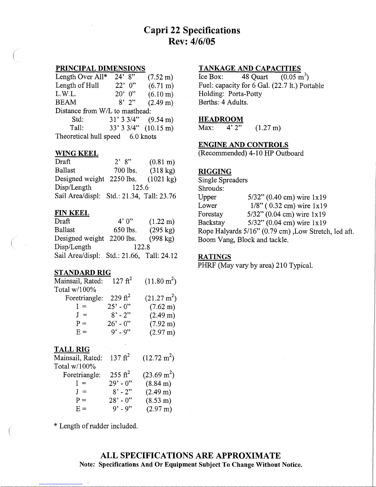
PRINCIPAL DIMENSIONS
Length Over All* 24' 8" (7.52 m)
Length ofHull 22'
0"
L.W.L. 20' 0" (6.10 m)
BEAM 8'
2" (2.49 m)
Distance from W /L to masthead:
Std: 31' 3 3/4" (9.54 m)
Tall: 33' 3
Theoretical hull speed
WING
KEEL
Draft
Ballast
Designed weight
3/4" (10.15 m)
6.0 knots
2'
8" (0.81
700 lbs. (318 kg)
2250 lbs. (1021 kg)
Disp/Length
Sail Arealdispl:
FIN
KEEL
Draft
Std.: 21.34, Tall: 23.76
4'
0" (1.22
Ballast 650 lbs. (295 kg)
2200
Designed weight
lbs.
Disp/Length 122.8
Sail Arealdispl: Std.: 21.66, Tall: 24.12
00%
RIG
25'-
26' - 0"
127
229
8'
9'
ft
2
ft
0"
- 2"
- 9"
2
STANDARD
Mainsail, Rated:
Total
w/1
F oretriangle:
I =
J =
P=
E=
125.6
(11.80 m
(21.27 m
(6.71
m)
m)
m)
(998 kg)
(7.62 m)
(2.49 m)
(7.92
m)
(2.97
m)
2
)
2
)
4/6/05
TANKAGE AND CAPACITIES
Ice Box:
48
Quart (0.05 m
Fuel: capacity for 6 Gal. (22.7 lt.) Portable
Holding: Porta-Potty
Berths: 4 Adults.
HEADROOM
Max:
ENGINE AND
4'
2"
(1.27 m)
CONTROLS
(Recommended) 4-10 HP Outboard
RIGGING
Single Spreaders
Shrouds:
Upper
Lower
Forestay
Backstay
Rope Halyards
5/32" (0.40 em) wire 1x19
1/8" ( 0.32 em) wire 1x19
5/32" (0.04 em) wire 1x19
5/32" (0.04 em) wire 1x19
5/16" (0.79 em) ,Low Stretch, led aft.
Boom Yang, Block and tackle.
RATINGS
PHRF (May vary by area)
210 Typical.
3
)
TALL
Mainsail, Rated:
RIG
137
ft
Total w/100%
F oretriangle:
I =
J = 8' - 2" (2.49
P=
E=
* Length
of
rudder included.
255
29' -
28'-
9'
ft
0"
0"
- 9"
ALL SPECIFICATIONS ARE APPROXIMATE
Note: Specifications And
2
2
(12.72 m
(23.69 m
(8.84 m)
m)
(8.53
m)
(2.97 m)
Or
Equipment Subject To Change Without Notice.
2
)
2
)
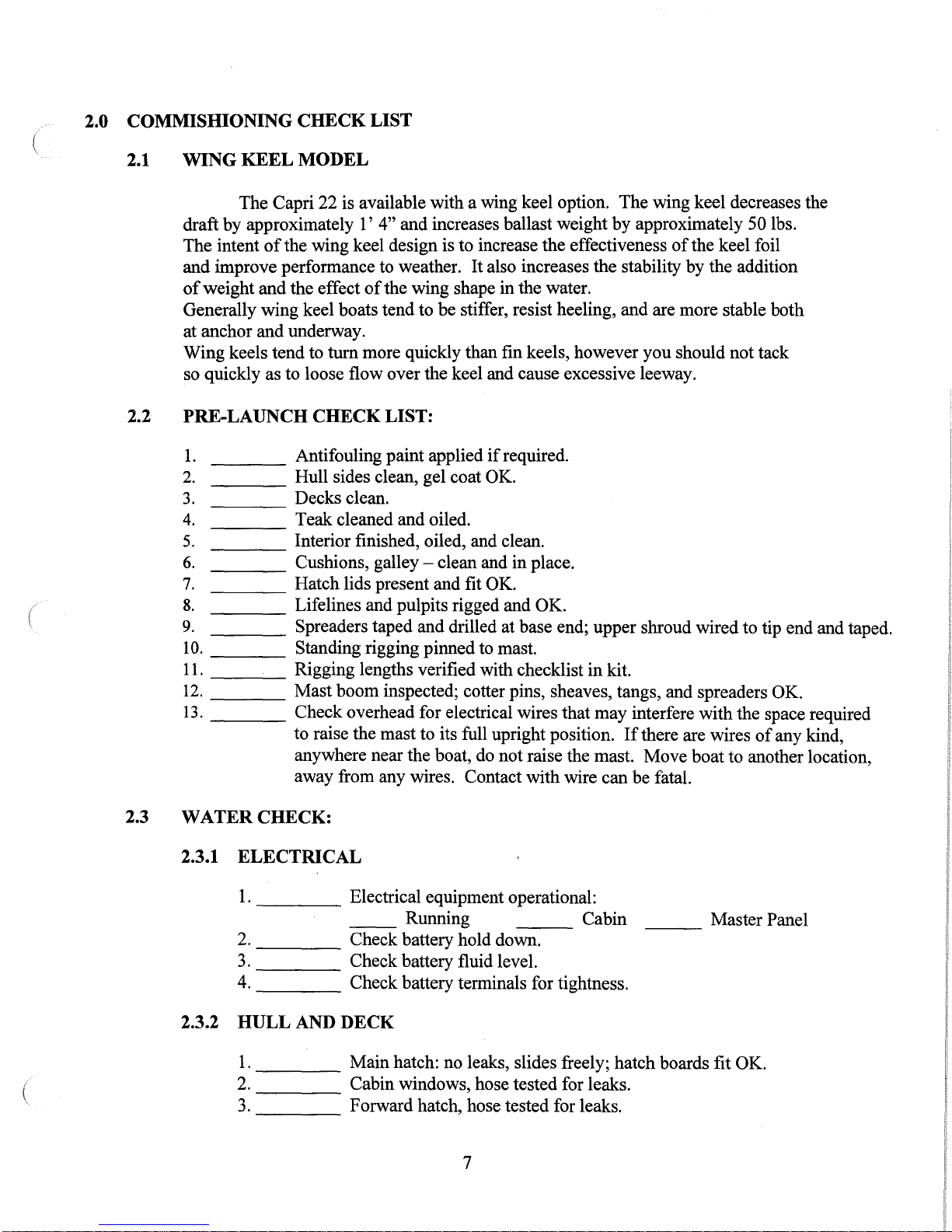
2.0 COMMISIDONING CHECK LIST
2.1
WING KEEL MODEL
The Capri 22 is available with a wing keel option. The wing keel decreases the
draft by approximately
of
The intent
and improve performance to weather.
of
weight and the effect
Generally wing keel boats tend to be stiffer, resist heeling, and are more stable both
at anchor and underway.
Wing keels tend to
so quickly as to loose flow over the keel and cause excessive leeway.
the wing keel design is to increase the effectiveness
1'
4"
and increases ballast weight
It
also increases the stability by the addition
of
the wing shape in the water.
tum
more quickly than fin keels, however you should not tack
by
approximately 50 lbs.
of
the keel foil
2.2 PRE-LAUNCH CHECK LIST:
____
1.
____
2.
3.
----
4.
----
5.
----
6.
---____
7.
____
(
8.
9.
10.
11.
12.
13.
____
____
__
____
____
Antifouling paint applied
Hull sides clean, gel coat OK.
Decks clean.
Teak cleaned and oiled.
Interior finished, oiled, and clean.
Cushions,
Hatch lids present and fit OK.
Lifelines and pulpits rigged and OK.
Spreaders taped and drilled at base end; upper shroud wired to tip end and taped.
Standing rigging pinned to mast.
___;_____
Rigging lengths verified with checklist
Mast boom inspected; cotter pins, sheaves, tangs, and spreaders OK.
Check overhead for electrical wires that may interfere with the space required
to raise the mast to its full upright position.
anywhere near the boat, do not raise the mast. Move boat to another location,
away from any wires. Contact with wire can be fatal.
galley-
clean and in place.
if
required.
in
kit.
If
there are wires
of
any kind,
2.3 WATER CHECK:
2.3.1 ELECTRICAL
1.
____
2.
____
3.
4. Check battery terminals for tightness.
2.3.2 HULL
1.
2.
3.
AND
____
Electrical equipment operational:
__
Check battery hold down.
Check battery fluid level.
Running Cabin
---
Master Panel
DECK
Main hatch: no leaks, slides freely; hatch boards fit OK.
Cabin windows, hose tested for leaks.
Forward hatch, hose tested for leaks.
7
2.3.3 RIGGING
1.
____
2.
3.
4.
5.
AND
HARDWARE
Mast stepped.
Pin, tape, and tune standing rigging.
Backstay adjuster, boom vang (if required).
Blocks, cars, cleats rigged, OK.
Test winches; winch handle present.
2.4 SAILING CHECK LIST
1.
____
2.
3.
4.
5.
6.
Tiller moves freely,
Sails and halyards, OK.
Boat performance under sail, OK.
All accessory equipment operates, OK.
All boat, engine, and accessory literature and/or manuals aboard.
Warranty cards completed and mailed, owner registration card attached,
owner informed
45
degrees minimum, to each side
of
warranty responsibilities.
of
center line.
8
3.0 YACHT SYSTEMS
3.1
RIGGING:
3.1.1 STEPPING
CAUTION: The aluminum and other metal parts conduct
electricity. Coming into contact with or near an electrical power line or
lightning can cause severe injury or death.
electrical power lines when sailing and/or launching the boat.
When trailering your boat, always
is necessary only to detach the forestay before lowering the mast.
1.
Before raising the mast, make sure halyards are neatly tied down and
that they are
to raise the mast unless the upper shrouds (those that pass over the
spreaders) and the aft lower shrouds are attached to the deck fittings and
the turnbuckles are well
must not be completely tightened, however, because slack is needed in
the shrouds to enable the mast to be fully raised. The backstay should be
attached to the transom chain plate. The upper shrouds, aft lower
shrouds, and backstay will keep the mast from falling over when it is
raised, therefore, all
the mast is raised.
THE
on
MAST:
proper sides
"started" into their barrels. The turnbuckles
of
these must be attached to the chain plates before
Stay away from overhead
try to undo as little rigging as possible.
of
the spreaders. You should never attempt
It
(
2. Make sure that the shrouds and stays are not fouled. Backstay should lie
clear
in
the water. It seems to be easier
stable. Also, it keeps other sailors form getting impatient while they
wait for you to move out
3.
Walk the mast aft and drop the mast foot into the mast step located
top
of
bolt and locking nut.
4.
One crew member should pull
while another pushes up
forward. With the mast erect, attach the forestay.
3.1.2 TUNING
Your mast is held aloft by the standing rigging (forestay, backstay,
upper shrouds, and aft, lower shrouds). The term
adjustment
of
the transom. You may step the mast on land or while the boat is
on
land because the boat is more
of
the launch area.
the deck, keeping the mast in centerline
on
a line tied securely to the forestay
on
the mast and walks from the cockpit
THE
MAST:
of
the standing rigging so that the mast remains
ofboat,
"tuning" refers to
insert the pivot
"in
column" (not
on
9

bent) when under load. This is accomplished by following the procedure
outlined below:
AT THE DOCK:
1.
Adjust forestay and backstay so that the mast is straight
Tie a bolt to a 6 to 7 foot long piece
of
bob, and tape the free end
as you can reach. This device will help
mast is perpendicular or not.
of
a building.
2. Adjust the upper shrouds so that the mast is deflected forward at the
spreaders, approximately 3 inches. This is called
should not
3. The upper shrouds should
upper shroud about 1" at shoulder height.
4. The aft lower shrouds (2
tighter than the upper shrouds. The lowers shrouds should be tensioned
equally until the middle
1-1
Y:z''.
middle
the mast aft, stabilize the mast and prevent "pumping" or excessive
movement
be
deflected sideways or athwartship.
The dynamic tension created by the spreaders pushing the
of
the mast forward and the lower shrouds pulling the middle
of
the middle
the line to the front
Otherwise, sight your mast with a comer
be
firm. A 50 pound push should deflect the
of
them) should be adjusted so that they are
of
the mast is pulled aft to reduce the prebend to
of
the mast fore and aft, when sailing.
of
light line to make a quick plumb
of
you
to determine whether the
"prebend". The mast
up
and down.
the mast as high up
of
3.1.3 RIGGING THE BOOM
1.
Attach the mainsheet block with becket to the "outboard" or aft end
the boom.
2.
Shackle mainsheet fiddle block with cam-cleat to the backstay traveler.
3.
"Dead-end" tie the mainsheet to the becket on the block
and then
through the fiddle block pulleys and the block pulley. Tie a
eight"
while under sail.
"reeve" the mainsheet by passing the line back and forth
knot at end
of
mainsheet to keep from losing the end
3.1.4 BENDING ON THE MAINSAIL
1.
Feed the clew
gooseneck fitting and pulling out the end
if
done by two persons, one feeding and the other pulling out.
2. Insert tack
grommet. Release the outhaulline (starboard, aft clam cleat underside
of
boom) and attach the outhaul shackle to the clew (aft end)
Pull
in
the line to remove wrinkles and re-cleat.
of
the mainsail into the groove
pin
at the gooseneck fitting, passing the
on
the boom
"figure
of
mainsheet
on
the
boom
of
boom. This is much easier
pin
starting at
through the sail's
of
the sail.
of
(
10
3.
Insert the battens noting that the battens are different lengths. The
correct battens must be used, shorter ones at the head and longer ones at
the foot
Shackle headboard
4.
of
the sail.
of
the mainsail to the halyard. Look aloft to ensure
that halyard is not fouled.
..
Start headboard sail slug and insert all slugs under in the correct order,
5
pushing the sail up the mast slightly as you go. Insert the stop in the
track after all the sail slugs have been inserted.
on
the mast just above the sail feed slot in the mast. With the stop in
Secure the stop in place
place the sail can be lowered or reefed without the slugs coming out
the track on the mast. Sail is now ready for hoisting.
of
3.1.5 BENDING
1.
Find tack
to the stem fitting at the bow using a shackle.
2.
Connect
the top snap in sequence.
3.
Shackle head
halyard is running clear and not wrapped around the forestay or
spreader.
4. Find middle
the
jib
outside
fairlead blocks that have been previously attached to the tracks that are
located
the ends
when you tack.
5.
Boats equipped with the factory-supplied roller furling gear for the jib,
should read all instructions supplied with the furling gear, before
operating the furling unit. The sail will sheet to the cabin top in the
normal fashion.
6.
The optional genoa will sheet to the tracks
sheets should lead around the shrouds to the blocks on the tracks and aft
to the optional winches, figure-eight knots in the ends
recommended.
ON
THE JIB
of
sail-
this is the forward lower comer
jib
to forestay by starting at the bottom snap and working up to
of
jib
to rope halyard, again sighting aloft to ensure that
of
jib sheet line and attach the
sail. Run the
of
the shrouds. Pass the ends
on
the cabin top
of
the
jib
sheet lines back to the cockpit keeping them
of
the boat. Tie figure-eight stopping knots
jib
sheets to keep them from pulling through the blocks
of
the
jib
jib
on
of
jib. Fasten the sail
sheet lines to the clew
sheets through the jib
the cockpit coaming. The
of
the sheets are
of
in
11

STANDARD
RIG
EXTRUSION
28'-0"
I
d
TALL
RIG
EXTRUSION
30'-0"
I
CHECK
OVERHANG
LENGTHS
BEFORE
Sic_PPING
J r
I
STANDARD
TALL
TOP
FITTING
BOTTOM
FITTING
FORESTAY
-
I
1'-4
1/2"
T-BOLT
5/16"
STUD
\
UPPER
SHROUDS
-
l
0'-5
1/4"
T-BOLT
5/16"
STUD
\
l
LOWER
SHROUDS
-
o'-6"
T-BOLT
1/4"
STUD
\
I
I
69-3/8"
BACKSTAY
FIXED
(std.) I
-
3'
- 3
5/8"
EYE
5/16"
PIN
5/16"
STUD
\,
~~
1'
-7"
EYE
5/16"
PIN
FORK
1/4"
PIN
BACKSTAY
(opt.)
ADJUSTABLE
11
2
"
H-
\
1/8"
Wire
Pennan~~,~-
STANDING
RIGGING
.w/
SnaP.
Hook
N.P.
to backstay
DESCRIPTION
LENGTH
MATERIAL
QTY.
RUNNING
RIGGING
STD.
TALL
DESCRIPTION
MATERIAL
LENGTH
QTY.
BACKSTAY
FIXED
5/32"
WIRE
1x19
31'-5
5/8"
32'-11
3/8"
1
SPINN
TOPPING
LIFT
(Performance
Opt.)
5/16"
LOW
STRCH
4o'
o"
1
BACKSTAY ADJUSTABLE
(opt.)
5/32"
WIRE
1x19
26'-6" 27'-9"
1
BACKSTAY ADJUSTER
LINE
(Perf.
Opt.)
1/4"
DACRON
17' o"
1
FORESTAY
5/32"
WIRE
1x19
25'-5"
29'-5
3/4"
1
REEFING
LINE
(on
boom)
1/4"
DACRON
23'
0"
2
UPPER
SHROUDS
5/32"
WIRE
1x19
24'-2
1/2"
28'-2
3/4"
2
BOOM
VANG
LINE
5/16"
DACRON
28'
0"
1
LOWER
SHROUDS
1/8"
WIRE
1x19
12'-5
1/2"
14'-4
1/2"
2
~
FORE
GUY
(Performance
Option)
5/16"
DACRON
25'
0"
1
BACKSTAY PURCHASE
(opt.)
5/32"
WIRE
7x19
7'-8" 7'-8"
1
N
GENOA
SHEET
(150% Genoa
Option)
3/8"
DACRON
55'
o"
1
B.S. SAFETY PENNANT
(opt.)
1/8"
WIRE
1x19 P.C.
3'-9"
3'-9"
1
JIB
SHEET
(135%
Std.) (delete
w/
150 Opt.)
3/8"
DACRON
40'
0"
1
TRAVELER
CONTROL
LINES
1/4"
DACRON
13' o"
2
SPINNAKER SHEET
(Performance
Option)
5/16"
DACRON
50'
0"
2
HALYARDS
MAIN
SHEET
3/8"
DACRON
45'
o"
1
DESCRIPTION
MATERIAL
LENGTH
QTY.
OUTHAUL
(on
boom)
1/4"
DACRON
2o'
o"
1
STD.
TALL
CUNNINGHAM
1/4"
DACRON
1o' o"
1
MAINSAIL HAL
YARD
5/16"
LOW
STRETCH
64'-o"
70'-0"
1
CUNNINGHAM -REEFING
LINE
1/4"
DACRON
8'
o"
1
JIB
HALYARD
5/16"
LOW
STRETCH
57'-o"
61'-0"
1
SPINNAKER
HALYARD
(Perf. Opt.)
1 /
4"
LOW
STRETCH
60'-Q" 64'-Q"
1
BACKSTAY
PURCHASE
!---,
WIRE
BLOCK~
©&~~D
Sailboats
t})
~
21200 VICTORY
BLVD.
/.
TOGGLE
~
WOODLAND HILLS, CA.
91367-(818)884-
7700
BACKSTAY
SAFETY
PENNANT
SCALE:
NONE
APPROVED
BY:
DRAWN
BY
NOTES:
1)
TOLERANCES
±1/2"
DATE:
10-22-91
DANIEL
CASAL
2)
MEASUREMENTS
FROM
CENTER
OF
EYE
TO
CENTER
OF
EYE
OR
END
OF
STUD
TITLE:
REV.
18
FURLING
LINE
DELETED
FOR
COl
FF2
FURLING
6/28/04
RIGGING
LENGTH
REV.
17
B.S.
ADJ.
LINE
TO
1/4" x 17'
was
5/16" x 28'
1/19/04
REV.
16
BACKSTAY
ADJUSTER
LINE
TO
5/16"
was
3/8"
11/17/03
REV.
15
ADDED
FURLING
LINE
FOR
SCHAEFER
SNAP
FURLING
HULLS
1032 + 5/15/03
BOAT:
DRAWING
NUMBER
REV.
14
LABELED
LINES
FOR
OPTIONS
8.16.02
REV.
13
(2)
TRAVELER
LINES
13'
WAS
8'
7.26.02
HULL#
996 -UP
CAPRI
22
220-34001-18
REV.
12
(2)
REEFING
LINES
23'
WAS
1X17',
OUTHAUL
WAS
4'.
8.21.01
22
I
I
I
I
I
I
I
I
I
I
I
I
I
I
I
I
I
I
I
I
I
I
I
I
I~
:a
I
I
!<D
fN
I
I
II
I
I
:()._
I
-------
I
I
I
I
I
I
I
I
I
I
I
I
I
I
I
I
I
I
I
I
I
,,
'-..
............................
,
'
'
'
'
'
\
'
\
\
\
\
\
I
\
I
I
I
I
I
I
I
I
I
0
L()
C'\1
II
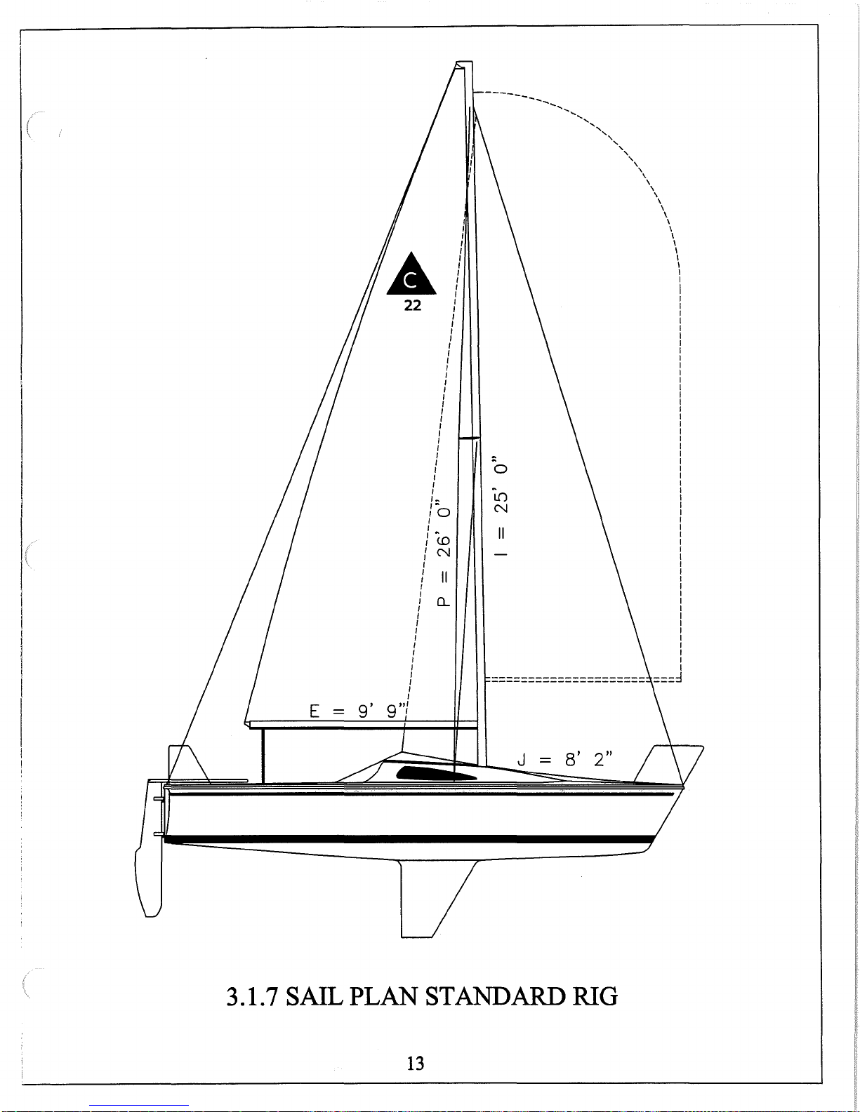
3.1.7
SAIL
PLAN
13
J
STANDARD
8'
2"
RIG
-------
,,
.........................
,
'
'
'
'
\
'
\
'
\
'
\
\
\
\
I
I
I
I
I
\
I
22
I
I
I
I
I
I
I
I
I
I
I
I
I
I
I
I
I
I
I
I
I
I
I
I
I
I
I
I
I
I
I
I
I
I
I
I
ll:
/0
I
I
I
CX)
I
I
N
I
I
I
II
I
I
I
Q_
I
0
~
m
N
II
===========
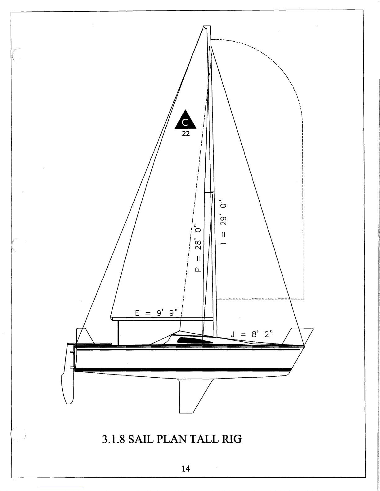
3.1.8
E
SAIL
PLAN
14
TALL
J
-
RIG
8'
2"
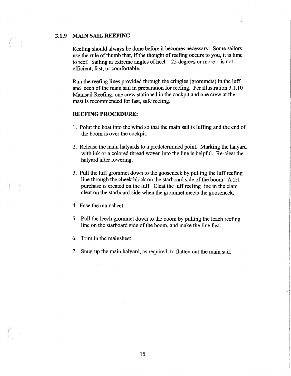
3.1.9 MAIN SAIL REEFING
Reefing should always be done before it becomes necessary. Some sailors
of
use the rule
thumb that,
to reef. Sailing at extreme angles
or
efficient, fast,
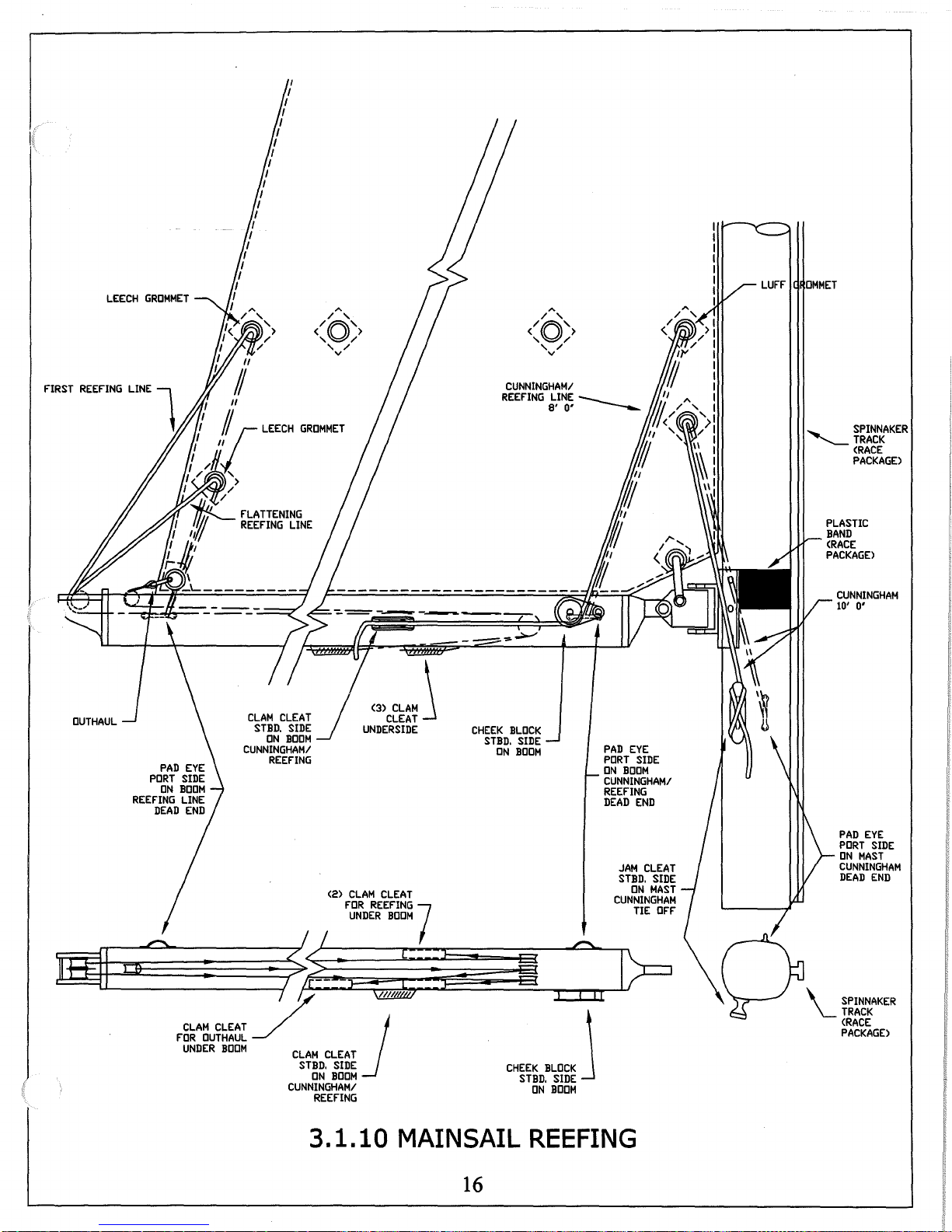
Run
the reefing lines provided through the cringles (grommets)
and leech
of
comfortable.
the main sail
Mainsail Reefing, one crew stationed in the cockpit and one crew at the
mast is recommended for fast, safe reefing.
REEFING PROCEDURE:
1.
Point the boat into the wind so that the main sail is luffing and the end
the
boom
2. Release the main halyards to a predetermined point. Marking the halyard
with ink
halyard after lowering.
3.
Pull the
line through the cheek block
purchase is created
cleat
is over the cockpit.
or
a colored thread woven into the line is helpful. Re-cleat the
luff
grommet down to the gooseneck
on
on
the starboard side when the grommet meets the gooseneck.
if
the thought
ofheel-
in
preparation for reefing.
on
the luff. Cleat the
of
reefing occurs to you,
25 degrees or
the starboard side
luff
more-
Per
illustration 3 .1.1 0
by
pulling the
of
the boom. A 2:1
reefing line
it
is
in
the
luff
in
the clam
is time
not
luff
of
reefing
4. Ease the mainsheet.
5.
Pull the leech grommet down to the boom
line
on
the starboard side
6. Trim
7.
in
the mainsheet.
Snug up the main halyard, as required, to flatten out the
of
the boom, and make the line fast.
by
pulling the leach reefing
main
sail.
15
I
F"IRST
LEECH
REEF"ING
GROMMET
LINE
LEECH
FLATTENING
REEF"ING
LINE
"'
/ '
/Q\
,y/
v
' /
GROMMET
"'
/ '
<O>
' / v
'-
SPINNAKER
-.........____TRACK
<RACE
PACKAGE>
Im...___l
:_:
CLAM
F"IlR
UNDER
<3)
CLAM
\
CLEAT
CLEAT
BOOM
j
CHEEK
STBD.
ON
BLOCK
SIDE
BOOM
CLAM
CLEAT
STBD.
SIDE
ON
BOOM
CUNNINGHAM/
REEF"ING
<2>
UNDERSIDE
CLAM
F"llR
REEF"ING
UNDER
7
•
----~·
CLEAT
OUTHAUL
BOOM
~i;,_
/
~
__/'
CLAM
CLEAT
STBD.
ON
CUNNINGHAM/
REEF"ING
=~~i
I
J~----
SIDE
BOOM
CHEEk
STBD.
PAD
EYE
PORT
ON
BOOM
CUNNINGHAM/
REEFING
DEAD
:I>=
"'"''
I
SIDE
BOOM
J
ON
SIDE
END
CUNNINGHAM
10'
0'
PAD
EYE
PORT
SIDE
ON
MAST
CUNNINGHAM
DEAD
END
~\_SPINNAKER
yu
TRACK
<RACE
PACKAGE>
3.1.10
MAINSAIL
16
REEFING
-
-l
P
URCHASE
BACKSTA! X
7'
8'
-----...__
SIS~~.
:IRE
7X19
---.._
RIVIT
'WI
COTTER
RING
RIVET
'WI
COTTER
PIN
-~~---------------------------------------------------------------------------
FORK
ON
BACKSTAY
'~
'-"-
'WIRE
BLOCK
BACKSTAY
_/
ADJUSTER LINE
318'
Ill X 28'
DACRON
FIDDLE
BLOCK
'WI
SAFTEY
PENNANT
118'
Ill X 3'
9'
r
PLASTIC
COATED
1X19
'WIRE
BECKET
AND
-----
CAM
CLEAT
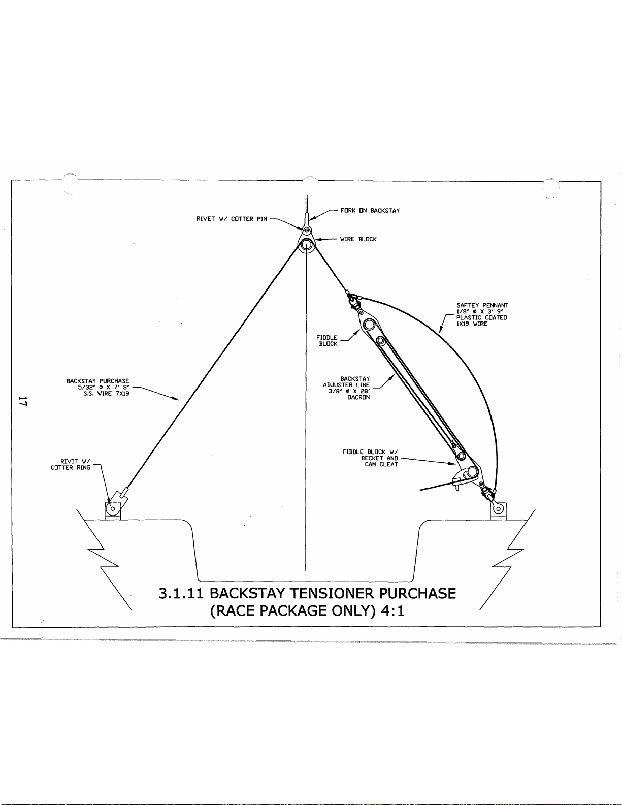
3.1.11
BACKSTAY TENSIONER PURCHASE
(RACE
PACKAGE
ONLY)
4:1
 Loading...