

Page 1

Page 2

Page 3

CATALINA 310
OWNER'S
MANUAL
Revised
5/1100
Page 4

FOREWORD
Congratulations on the acquisition of your new Catalina Yacht. All Catalina
yachts are designed and built with care using quality materials to assure you
years of sailing enjoyment with a minimum of upkeep and maintenance.
Before attempting maintenance or operation of your Catalina Yacht, please
read the Catalina Yachts Limited Warranty booklet and fill out the enclosed
warranty registration card.
The registration card enables Catalina to inform you of developments and
modifications to enhance the performance or comfort of your yacht. It is
also important to be able to contact owners to comply with Coast Guard
defect notification requirements.
The launching and rigging of your Catalina Yacht should be handled by
experienced boat yard personnel under the direction of your authorized
dealer.
The index page lists the contents of this manual. Warrantees and
information regarding installed optional equipment have been included when
available and applicable.
Maintaining your yacht properly can become a satisfying part of your sailing
activities. A regular inspection is the best preventive maintenance. It will
help keep your boat safe and in good condition while in use, and insure
peace of mind when the boat is left unattended.
Take good care of your boat and take the time to learn and practice good
seamanship.
1
Page 5
PREFACE
This manual is intended and supplied to help owners of Catalina Yachts
understand their boats and answer common questions about maintenance and
systems design specific to their boat.
This manual is not intended to provide sailing instructions. It is assumed the
operator will consult books written for that purpose, or take sailing lessons
or courses to gain knowledge necessary for the safe operation of the vessel.
The systems descriptions and illustrations in this manual apply to boats built
at the time of publication. Our policy of constant improvement necessitates
that changes have been made to the boat since its introduction. Therefore,
these illustrations and descriptions may not apply to boats built before the
time of publication.
Owners of earlier hulls, who have questions not answered herein should
consult with their local Catalina dealer, or write to, or e-mail Catalina
Yachts. Please include your hull number in all correspondence.
The maintenance check lists contained within this manual are intended as
guidelines for boats in normal service under typical conditions.
Climate and use will vary and may require additional or special
maintenance. Consult with your local boat yard or Catalina dealer for
specific maintenance and precautions recommended for your purposes and
climate.
Caution: The aluminum and other metal parts conduct electricity. Coming
in contact with or near an electrical power line or lightening can cause
severe injury or death. Stay away from overhead electrical power lines
when sailing and!or launching the boat.
2
Page 6

TABLE OF CONTENTS
PAGE
Forward
1
Preface
2
Table of Contents
3
Commissioning Check List
6
Maintenance Check List
10
Specifications
13
Sail Plan
14
Spar and Rigging Maintenance
15
Rigging Lengths
20
Deck Plan
21
Mainsheet Arrangement
22
Mainsheet Traveler
23
Boom Yang
24
Solid Yang and Purchase
25
Halyards Arrangement
26
Shroud Rigging
27
Mast Sub Assembly
28
Boom
30
Outhaul Assembly
31
~
3
Page 7

~
Electrical 12 Volt DC
32
Electrical Plan, DC
35
Mast Light Wiring
37
Electrical, AC 1101115 Volt
38
AC Plan
40
115 VAC Wiring Diagram
41
230 VAC Wiring Diagram
42
Control Panel 230 VACI12 VDC
43
Plumbing
45
Plumbing Plan
48
.~
_/
Head Plumbing
49
Auxiliary Power
50
Packing Gland 55
Prop Shaft and Log Alignment Procedure 56
Shaft Alignment Illustration 57
25XP Harness to Seaward Helm Pod
58
Steering
59
Accommodation 60
4
Page 8

Accommodations Plan 62
LPG Plan 63
Decommissioning 64
OwnerlUser Responsibility 67
Lightning Protection 70
Commissioning Package 79
Literature and warranties for equipment, which may be supplied 80
with this manual.
Equipment and Materials Log 81
5
Page 9
COMMISSIONING CHECK LIST
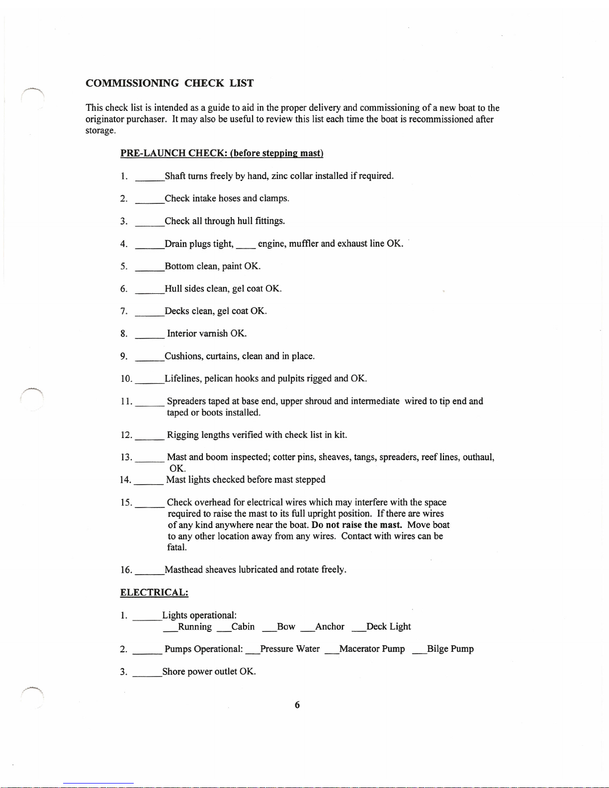
This check list is intended as a guide to aid in the proper delivery and commissioning of a new boat to the
originator purchaser. It may also be useful to review this list each time the boat is recommissioned after
storage.
PRE-LAUNCH CHECK: (before stepping mast)
1. Shaft turns freely by hand, zinc collar installed if required.
2. Check intake hoses and clamps.
3. __ Check all through hull fittings.
4. Drain plugs tight, __ engine, muffler and exhaust line OK.
5. Bottom clean, paint OK.
6. Hull sides clean, gel coat OK.
7. Decks clean, gel coat OK.
8. Interior varnish OK.
9. Cushions, curtains, clean and in place.
10. Lifelines, pelican hooks and pulpits rigged and OK.
11. Spreaders taped at base end, upper shroud and intermediate wired to tip end and
taped or boots installed.
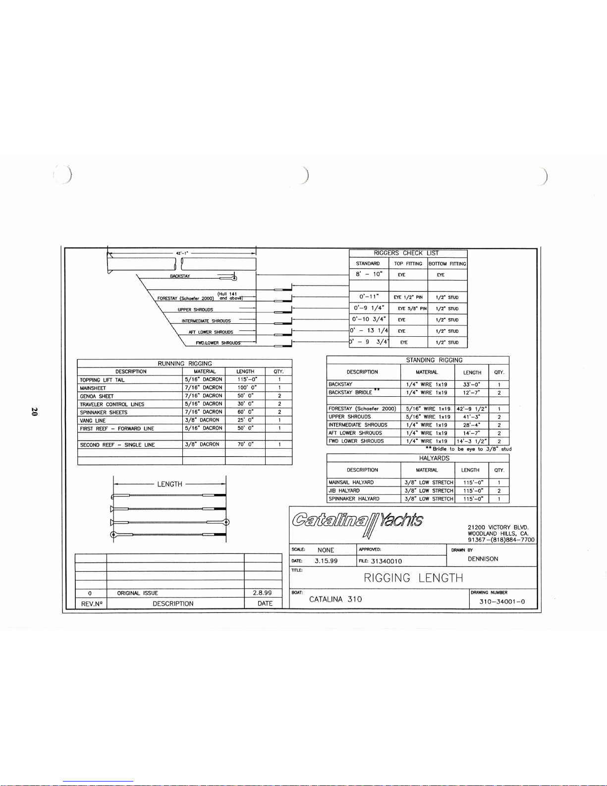
12. Rigging lengths verified with check list in kit.
13. Mast and boom inspected; cotter pins, sheaves, tangs, spreaders, reef lines, outhaul,
OK.
14. Mast lights checked before mast stepped
15. Check overhead for electrical wires which may interfere with the space
required to raise the mast to its full upright position. If there are wires
of any kind anywhere near the boat. Do not raise the mast. Move boat
to any other location away from any wires. Contact with wires can be
fatal.
16. Masthead sheaves lubricated and rotate freely.
ELECTRICAL:
1. Lights operational:
_Running _Cabin _Bow _Anchor _Deck Light
2. Pumps Operational: _Pressure Water _Macerator Pump _Bilge Pump
3. Shore power outlet OK.
6
Page 10
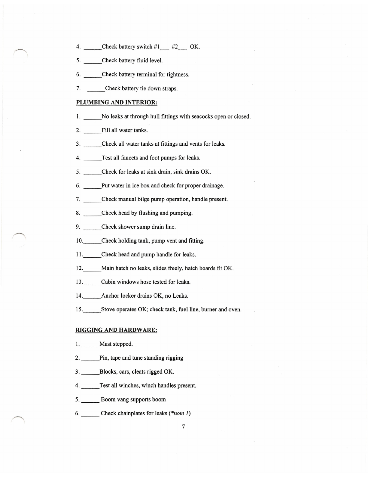
4. __ Check battery switch #1_ #2_ OK.
5. Check battery fluid level.
6. Check battery terminal for tightness.
7. Check battery tie down straps.
PLUMBING AND INTERIOR:
1. No leaks at through hull fittings with seacocks open or closed.
2. Fill all water tanks.
3. Check all water tanks at fittings and vents for leaks.
4. Test all faucets and foot pumps for leaks.
5. Check for leaks at sink drain, sink drains OK.
6. Put water in ice box and check for proper drainage.
7. Check manual bilge pump operation, handle present.
8. Check head by flushing and pumping.
9. Check shower sump drain line.
IO. Check holding tank, pump vent and fitting.
11. Check head and pump handle for leaks.
12. Main hatch no leaks, slides freely, hatch boards fit OK.
13. Cabin windows hose tested for leaks.
14. Anchor locker drains OK, no Leaks.
15. Stove operates OK; check tank, fuel line, burner and oven.
RIGGING AND HARDWARE:
1. Mast stepped.
2. Pin, tape and tune standing rigging
3. Blocks, cars, cleats rigged OK.
4. Test all winches, winch handles present.
5. Boom vang supports boom
6. Check chainplates for leaks (*note
1)
7
Page 11
ENGINE:
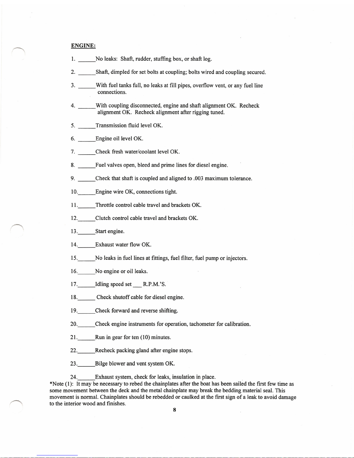
1. No leaks: Shaft, rudder, stuffing box, or shaft log.
2. Shaft, dimpled for set bolts at coupling; bolts wired and coupling secured.
3. With fuel tanks full, no leaks at fill pipes, overflow vent, or any fuel line
connections.
4. With coupling disconnected, engine and shaft alignment OK. Recheck
alignment OK. Recheck alignment after rigging tuned.
5. Transmission fluid level OK.
6. Engine oil level OK.
7. Check fresh water/coolant level OK.
8. Fuel valves open, bleed and prime lines for diesel engine.
9. Check that shaft is coupled and aligned to .003 maximum tolerance.
1O. Engine wire OK, connections tight.
11. Throttle control cable travel and brackets OK.
12. Clutch control cable travel and brackets OK.
13. Start engine.
14. Exhaust water flow OK.
15. No leaks in fuel lines at fittings, fuel filter, fuel pump or injectors.
16. No engine or oil leaks.
17. Idling speed set _ R.P.M.'S.
18. Check shutoff cable for diesel engine.
19. Check forward and reverse shifting.
20. Check engine instruments for operation, tachometer for calibration.
21. Run in gear for ten (10) minutes.
22. Recheck packing gland after engine stops.
23. Bilge blower and vent system OK.
24. Exhaust system, check for leaks, insulation in place.
*Note (1): It may be necessary to rebed the chainplates after the boat has been sailed the first few time as
some movement between the deck and the metal chainplate may break the bedding material seal. This
movement is normal. Chainplates should be rebedded or caulked at the first sign of a leak to avoid damage
to the interior wood and fmishes.
8
Page 12
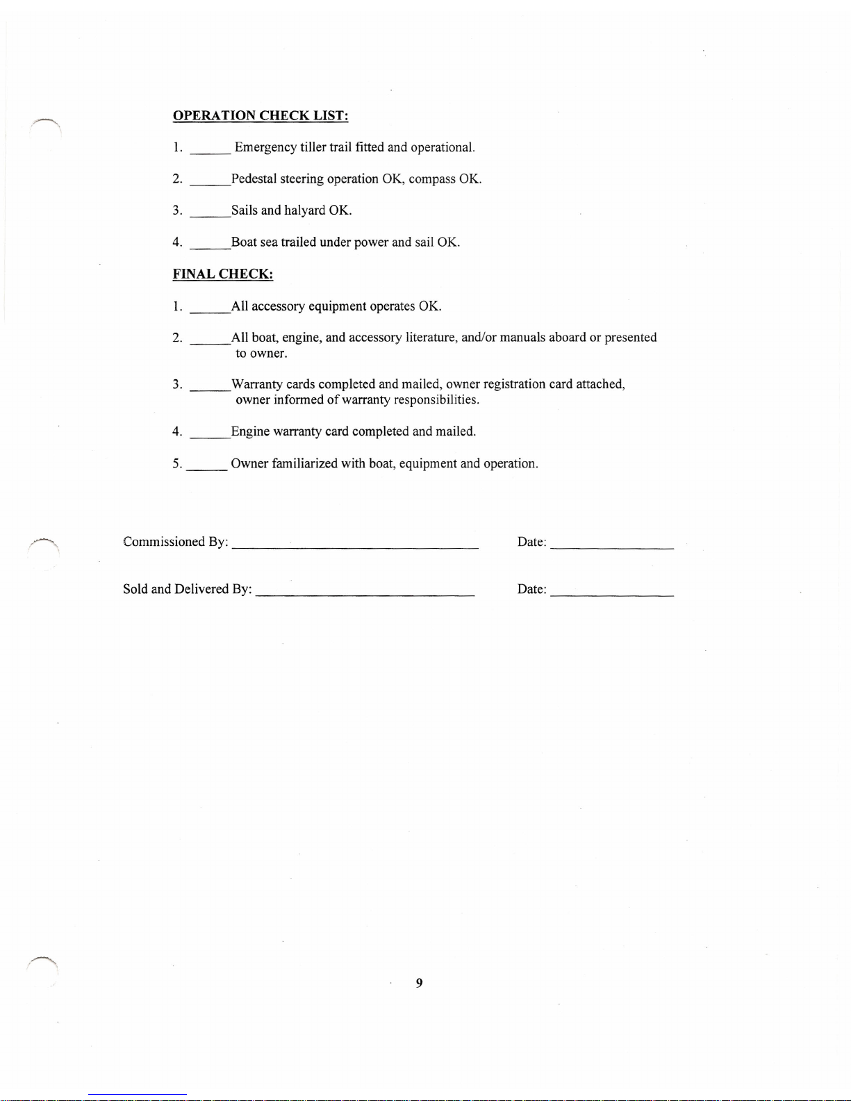
OPERATION CHECK LIST:
1. Emergency tiller trail fitted and operational.
2. Pedestal steering operation OK, compass OK.
3. Sails and halyard OK.
4. Boat sea trailed under power and sail OK.
FINAL CHECK:
1. All accessory equipment operates OK.
2. All boat, engine, and accessory literature, and/or manuals aboard or presented
to owner.
3. Warranty cards completed and mailed, owner registration card attached,
owner informed of warranty responsibilities.
4. Engine warranty card completed and mailed.
5. Owner familiarized with boat, equipment and operation.
Commissioned By: _
Date:
--------------
Sold and Delivered By: _
Date:
--------------
9
Page 13
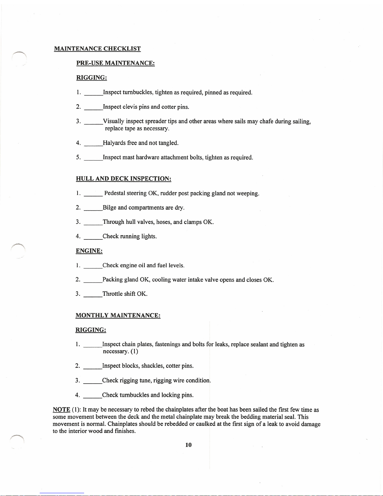
MAINTENANCE CHECKLIST
PRE-USE MAINTENANCE:
RIGGING:
1. Inspect turnbuckles, tighten as required, pinned as required.
2. Inspect clevis pins and cotter pins.
3. Visually inspect spreader tips and other areas where sails may chafe during sailing,
replace tape as necessary.
4. Halyards free and not tangled.
5. Inspect mast hardware attachment bolts, tighten as required.
HULL AND DECK INSPECTION:
1. Pedestal steering OK, rudder post packing gland not weeping.
2. Bilge and compartments are dry.
3. Through
hull
valves, hoses, and clamps OK.
4. Check running lights.
ENGINE:
1. Check engine oil and fuel levels.
2. Packing gland OK, cooling water intake valve opens and closes OK.
3. Throttle shift OK.
MONTHLY MAINTENANCE:
RIGGING:
1. Inspect chain plates, fastenings and bolts for leaks, replace sealant and tighten as
necessary. (1)
2. Inspect blocks, shackles, cotter pins.
3. Check rigging tune, rigging wire condition.
4. Check turnbuckles and locking pins.
NOTE (1): It may be necessary to rebed the chainplates after the boat has been sailed the first few time as
some movement between the deck and the metal chainplate may break the bedding material seal. This
movement is normal. Chainplates should be rebedded or caulked at the first sign of a leak to avoid damage
to the interior wood and finishes.
10
Page 14

HULL AND DECK:
1. Inspect hull valves open and close freely.
2. Winches turn freely, lubricate as per manufacturer's recommendations.
3. Clean and wax gel coat surfaces as necessary.
ENGINE:
1. Check oil and fluid levels, visually check for fluid leaks.
2. Battery: Check fluid levels and tie downs.
3. Tighten all bolts and nuts to proper torque.
4. Check fuel tank fittings and hose clamps.
5. Disassemble and inspect cooling system anti-siphon
6. Check bolts.
7. Check filters.
SEASONAL MAINTENANCE:
RIGGING:
1. Mast head pins and sheaves turn freely.
2. Halyards and shackles are in good condition. (Refer to Rigging, Stepping the Mast)
3. Spreader tips and bases, and mast fittings OK.
4. All shroud terminations and swedged fittings OK, check for cracks or corrosion.
5. Gooseneck assembly and boom assembly OK.
6. Mast, boom and spreaders cleaned and waxed.
7. Lifelines, pelican hooks, and stanchions all OK, all pins and fittings are secure, cotter
rings taped. Turnbuckles, pelican hooks and connector loops OK, screw fittings
checked for thread wear.
HULL, DECK and CABIN:
1. All chainplates and through bolts tight.
2. Disassemble winches and lubricate bearings and pawls.
3. Inspect and coat electrical system connections, battery tie downs and terminal
connectors to prevent corrosion.
4. Drain and flush fresh water system.
11
Page 15

5. Check head and anti-siphon valve in toilet.
6. Hatch gaskets and hold down fasteners OK.
7. Bottom, keel and rudder condition of anti-fouling paint OK.
8. Lifelines, stanchions and pelican hooks OK.
ENGINE:
1. Check shaft alignment, repack stuffing box if necessary.
2. Clean motor thoroughly.
3. Inspect fuel system.
4. Tune engine as per manufacturer's recommendations.
5. Exhaust system check for leaks, or deterioration, insulation in place.
12
Page 16
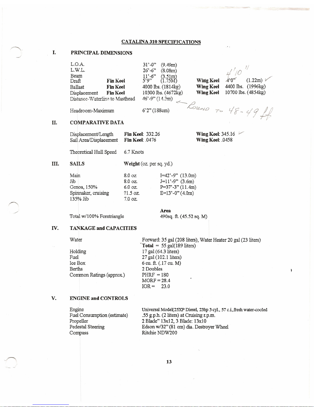
I.
PRINCIPAL DIMENSIONS
CATALINA 310 SPECIFICATIONS
L.O.A.
L.W.L.
Beam
Draft
Fin Keel
Ballast
Fin Keel
Displacement
Fin Keel
Distance-Waterline to Masthead
Headroom-Maximum
II. COMPARATIVE DATA
31' -0" (9.49m)
26' -6" (8.08m)
11'
-6" (3.5IJIl]
5'9" (1.75M)
4000
lbs,
(l8l4kg)
10300 lbs. (4672kg)
46' -9" (1 4.3m)
WiItgKeel
Wing Keel
Wing Keel
/ 1/
t/
/0
42-0""
(1.22m)
v"
44001bs. (1996kg)
10700 lbs. (4854kg)
6'2" (l88cm)
Displacement/Length
Fin Keel:
332.26
Sail AreaIDisplacement
Fin Keel:
.0476
Wing Keel:
345.16
V
Wing Keel:
.0458
Theoretical Hull Speed 6.7 Knots
III. SAILS
Weight
(oz. per sq. yd.)
Main
Jib
Genoa, 150%
Spinnaker, cruising
135% Jib
8.00z
8.0oz.
6.0 oz.
71.5
oz.
7.0 oz.
Total w/IOO% Foretriangle
IV. TANKAGE
and
CAPACITIES
Water
Holding
Fuel
Ice Box
Berths
Common Ratings (approx.)
v.
ENGINE and CONTROLS
Engine
Fuel Consumption (estimate)
Propeller
Pedestal Steering
Compass
I=42' -9" (13.Orn)
J=l1' -9" (3.6m)
P=3T
-3"
(11.4m)
E=13' -0" (4.Orn)
Area
490sq. ft. (45.52 sq. M)
Forward: 35 gal (208 liters), Water Heater 20 gal (23 liters)
"Total
= 55 gal(189 liters)
17 gal (64.3 liters)
27 gal (102.1 liters)
6 cu.
ft.
(.17 cu. M)
2 Doubles
PHRF = 180
MORF=28.4
IOR= 23.0
Universal MOde1(25XP Diesel. 23hp 3
cyl.,
57 c.i,ftesh water-cooled
.55 g.p.h. (2 liters) at Cruising r.p.m.
2 Blade" l3x12, 3 Blade: 13xlO
Edson w132" (81 ern) dia. Destroyer Wheel
Ritchie NDW200
13
Page 17
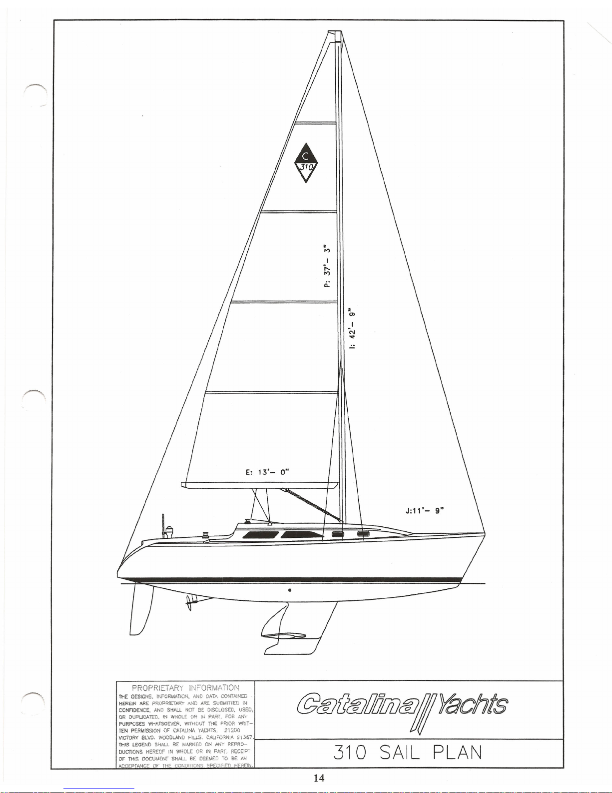
E: 13'- 0"
J:11'- 9"
•
14
Page 18
SPAR AND RIGGING MAINTENANCE:
STANDING RIGGING:
Your boat is equipped with stainless steel standing rigging, and Dacron running rigging, to give
you years of trouble-free service. However, due to normal wear and tear, it is recommended that
a periodic inspection be made on all fittings and wires. Turnbuckles should never be neglected
and should be unscrewed from time to time in order that they do not seize. Every three months
should be about right for the average sailor. A slightly bent turnbuckle shaft or broken wire in
your shrouds should be replaced immediately.
Under most conditions, 1 X 19 standing rigging has a safe "working" life span of approximately
five years: seven years under ideal conditions. Factors which reduce the life of the wire are
environmental factors such as high humidity (Florida, the Caribbean, and Gulf States); high
salinity (Great Lakes, Gulf States, or mooring near a sea wall with constant salt spray); extremes
in temperature; and industrial pollution (pulp mills, generating plants, acid rains, and smog).
High loading of the rigging as required in most racing boats also induces stress in the rigging
system. Many of us have to deal with at least one of these conditions and should consider
replacing standing rigging at the five year limit.
Unlike running rigging wire rope, which gives us clear signs that it is deteriorating by broken
strands and "meat hooks", standing rigging may give no sign that failure is imminent. The usual
point of failure of stay or shroud is approximately W' inside the bottom swedged threaded stud
fitting which threads into the turnbuckle barrel.
Although the stud is compressed around the wire during the swedging process, salt water and
pollutants work down into the tine cavities between the wire strands and the inevitable corrosive
process starts in the crevice first time the rigging becomes wet with salt water.
A common method of visually monitoring swedge fitting conditions, employed by distance racers
and cruisers, is to dab a small ring of enamel paint around the joint between the wire and the
swedge fitting. This will help provide a means to see if the wire is pulling out of the fitting.
Another technique used to check the condition of swedge fittings is a "dye penetrant" test. This
simple test will detect any cracks which may develop in the fittings due to internal pressure from
the corrosive process. Inexpensive dye tests kits usually are available from most welding supply
stores. Dye tests usually are not required by weekend sailors, but may be done before an extended
cruise or ocean passage if any doubt about the integrity of the rigging exists.
All stainless steel wire rope rigging will develop some rust film when new. This is normal.
The rust is caused by two factors. When wire rope is manufactured, the wire strands are fed over
steel rollers during the process of twisting or laying the wire. Trace amounts of the ferrous steel
from the rollers and dyes are transferred to the wire strands. As this small amount of steel rusts
it causes a film on the new wire.
The second cause of the rust film on new wire is the microscopic veins of ferrous material which
exist in all stainless steel. After a period of time, as the surface material veins are depleted, and
the stainless steel has been cleaned several times, new rust film development will slow to a
minimum.
For the average sailor, the best insurance against a rigging failure is a periodic (every six months
is recommended) inspection of all rigging parts, including turnbuckles, and replacement of
standing rigging as required.
15
Page 19
IMPORTANT: Ifill!Y wear or sign of broken strands is found on the running or standing
rigging, it is time to replace that part. Using your boat when the rigging
is worn could cause the rigging to fail when you least expect it.
FITTINGS:
Marine fittings today need minimal maintenance. Deck hardware should be hosed down with
freshwater after each sail in salt water. Stainless steel fittings such as pulpits and lifeline
stanchions should be cleaned and waxed periodically to maintain their appearance. Winches
require occasional cleaning and lubrication. Where possible, a maintenance brochure for your
winches has been included in this manual. Masthead fittings, halyard sheaves, etc., should be
inspected, cleaned and lubricated periodically. Keep your equipment clean of dirt and salt.
SPARS:
Like all other fittings, the mast and boom suffer from salt water, air and spray. These should be
kept waxed where possible, and at least always hosed down with fresh water. Always see that the
halyards are tied off away from the mast. This will eliminate slapping in the wind, and
subsequent marking of the mast. Find a high pressure nozzle and shoot fresh water to the top of
the mast and spreaders. This will help keep your sails clean, too, as they rub on the mast and
spreaders.
SAIL MAINTENACE:
Your sails should be protected from chafmg. This can be done by either padding the areas that
touch the sail or by having your sailmaker attach chafe patches to the sails themselves.
You should check your sails frequently for any signs of wear and have any tears or frayed stitches
repaired immediately.
Sails should never be stored in the sun because they are susceptible to decay through exposure to
too much ultraviolet light. Always keep your sails covered when they are not is use.
Sails should never be put away wet. If they are wet after sailing, leave them in loose bundles and
dry them at your first opportunity.
For most problems, such as common dirt, dried or caked salt, etc., try scrubbing the surface with
a soft bristled brush and liquid detergent. Avoid harsh powder detergents and stiff brushes, as
they may damage the finish or stitching. This approach should work nicely for most
applications. More severe stains can be taken care of by the following:
BLOOD:
IMPORTANT: FOR WHITE SAILS ONLY
Soak the stained portion for 10 to 20 minutes in a solution of bleach (Clorox)
and warm water. Generally 10 parts water to 1part bleach. Scrub and repeat
if necessary. Rinse thoroughly, particularly nylon, and dry thoroughly.
OIL. GREASE TAR. WAX: Warm water, soap and elbow grease seem to be effective. On hard
stains, proprietary stain remover and dry cleaning fluids should do the trick.
Be careful to remove all fluids, as they can soften the various resinated coatings.
RUST AND METALLIC STAINS: These types of stains are very often the most frustrating and
difficult to remove. First scrub with soap and water, and apply acetone,
M.E.K., or alcohol. As a last resort, you might try a diluted mixture (5%) of
Oxalic soaked for 10 to 15 minutes. Hydrochloric Acid, 2 parts to 100 in
warm water, will also work.
16
Page 20
MILDEW:
Hot soapy water with a little bleach will generally prevail. After scrubbing,
leave the solution on the fabric for a few minutes and rinse thoroughly. When
using a bleach, a residual chlorine smell may be present after rinsing. A 1
%
solution of Thiosulphate (photographers' Hypo) should remove all chlorine
traces. Here again, rinse and dry well.
PAINT AND VARNISH: Acetone and M.E.K. should remove most common paint stains.
Varnish can be easily removed with alcohol. Generally speaking, use all
solvents with care. Always rinse and dry thoroughly. It should be
emphasized that nylon ripstop spinnaker fabrics are less durable and more
sensitive than their polyester counterparts. Bleaches and solvents can ruin
nylon ifnot used properly.
Follow the above guidelines, take your sails into your sailmaker for periodic inspection, and you
will have many effective seasons of racing and cruising pleasure.
RIGGING:
STEPPING THE MAST:
1. Before stepping the mast check all standing rigging lengths against the checklist
2. Check all mast light wiring, be sure the masthead anchor light, steaming light and deck
light function, the wires exiting at the base of the spar should be taped up to prevent
damage when the spar is set on the step.
3.
Prepare to step the mast in the following sequence:
a) Check all rigging lengths and inspect all end fittings.
b) Attach all shrouds, forestay and backstay. Tape clevis pins and spreader tips, check
all halyards and tape to mast.
c) Connect and check mast wiring and mast light wiring at mast step.
d) Make electrical connections at base of mast for mast lights and check circuits.
e) Run halyards through turning blocks at deck.
f)
Tune rigging at dock and when under sail.
TUNING THE MAST:
Your mast is held aloft by the standing rigging (forestay, backstay, upper shrouds, intermediate
and lower shrouds). The term "tuning" refers to adjustment of the standing rigging so that the
mast remains "in column" (not bent) when under load, this is accomplished by following the
procedure outlined below:
AT THE DOCK:
1. Adjust fore stay and backstay so that the mast is straight up and down. Tie a bolt to a 6
to 7 foot long piece of light line to make a quick plumb bob, and tape the free end of the
line to t he front of the mast as high up as you can reach. This devise will help you to
determine if the mast is perpendicular or not. Otherwise, sight your mast with the
comer of a building.
2. Adjust the upper shrouds so that the mast is straight up and down athwartships. That is,
from side to side as opposed to bow and stem.
3. The upper shrouds should be firm but not bar tight. A 50 pound push should deflect the
upper shroud about I" at shoulder height.
17
Page 21
4. The lower shrouds (4 of them) should be adjusted so that they are looser than the upper
shrouds. While at dock, they should have no slack, but no tension either. No lower
shroud, when pushed, should deflect the mast more than any other shroud when pushed
equally hard. If this cannot be achieved, the upper shrouds are too tight. Back off one
half turn at a time on the upper shroud turnbuckles until the tension on the lower
shrouds is brought into balance.
UNDER SAIL:
The object of fine tuning is to have the mast "in column" (not bent fore or aft or athwartships)
when sailing in conditions typical for your area. This is accomplished through adjustments to the
lower shroud turnbuckles. Here are some points to look for:
I. When sailing on port tack, sight up the mast from the base. If the middle (where the
spreaders are) is sagging to leeward, take up equally on both port lower shrouds until the
mast is in "in column". Repeat this procedure on starboard tack.
2. If, when sighting up the mast while on port tack, the middle is bent forward (but not to
leeward) take up a turn on the port aft lower shroud and let out a turn on the port
forward lower shroud turnbuckle. Reverse these adjustments if the middle of the mast is
aft of the "in column" position.
3. If a perfectly straight mast is not obtained, the mast head (top) may be curved aft and to
leeward. The mast head should never be "hooked" forward nor to weather.
All rigging wire used on yachts has a tendency to stretch, especially on a new yacht and after you
have sailed in heavier wind than you are normally familiar with. Therefore, you should
periodically check the tension on the shrouds and stays, tightening them up if it is required.
Rigging, as well as tuning, becomes all too important when setting up the mast. A
knowledgeable person should oversee the rigging and tuning so as to eliminate the possibility of
an eccentric load which might occur with an improperly loaded shroud. Special attention should
be given to the initial stretch of the shrouds and a further gradual stretch of the wire over the first ~
few hard outings.
MAINSAIL REEFING:
Reefmg should always be done before it becomes necessary. Some sailors use the rule of thumb
that the thought of reefing occurs to you, it is time to reef. Sailing at extreme angles of heel,
25 degrees or more, is not efficient, fast or comfortable.
Your Catalina is equipped with single line reefmg, for reefing the mainsail. The system consists
of a line tied around the boom and reeved through the cringles, internal boom sheaves, and
blocks as shown in the illustration. A second reef line may be installed in a like manner, but to the
opposite side of the boom, and led to the starboard side of the cockpit.
Tie a loop of line around the main boom with a bowline, through the cringles at the first reef and
into the boom on the starboard sheave. The line exists the starboard forward sheave and through
the cringle in the sail at the first reef. Lead the line to the turning block at the base of the mast,
through the organizer on the deck and through the sheet stopper to the winch on the port side.
REEFING PROCEDURE:
1. Take up the slack in the main boom topping lift.
2. East the mainsheet.
18
Page 22

3. Release the main halyard on the starboard side of the cockpit, to a predetermined point.
(marking the halyard with ink or a colored thread into the line is helpful.) Recleat the
halyard after lowering.
4. Pull the luff and leach cringles down to the boom by pulling the reefing line through the
blocks with the port cockpit winch and cleat off. .
5. Trim in the mainsheet.
6. Tie off remaining reef points with lines around boom.
7. Snug up the main halyard as required to flatten out the mainsail.
8. Ease the topping lift.
19
Page 23
)
)
N
=
42'-,"
RIGGERS CHECK LIST
~ ~
I
STANDARD
TOP FIniNG
BOTTOM FIniNG
V
--,l
8' - 10"
BACKSTAY
m
m
'\
~
\ (Hull ,.,
fORESTAY (Scho.t8r 2000' end obover--
0'-11"
m 1/2" PIN
1/2"
sruo
\
UPPER SHROUDS
-
0'-9 1/4"
m
5/8"
PIN
1/2"
sruo
\
INTERMEDIATESHROUDS
-
0'-10 3/4"
m
1/2"
sruo
\
AfT LOWER SHROUDS -
O' - 13 1/4
m 1/2"
sruo
\
FWO.LOWER SHROUDS--
- 9
3/4'
m 1/2"
sruo
RUNNING RIGGING
STANDING RIGGING
DESCRIPTION MATERIAL LENGTH QTY.
DESCRIPTION
MATERIAL
LENGTH
QTY.
TOPPING LIfT TAIL
5/16" DACRON
115'-0"
1
MAiNSHEET
7/16" DACRON
100' 0"
1
BACKSTAY
1/4-" WIRE lx19 33'-0'
1
GENOA SHEET
7/16' DACRON
50' O·
2
BACKSTAY BRIDLE 1/4-' WIRE lx19
12'-7"
2
TRAVELER CONTROL LINES
5/16' DACRON
30' 0"
2
SPINNAKER SHEETS
7/16" DACRON
60' O·
2
FORESTAY (Schaefer 2000)
5/16" WIRE lx19 42' 9 1/2' 1
VANG LINE
3/8' DACRON
25' 0"
1
UPPER SHROUDS
5/16" WIRE lx19
41'-3"
2
FIRST REEF - FORWARD LINE
5/16" DACRON
50' 0"
1
INTERMEDIATE SHROUDS
1/ ••.• WIRE lx19
28·- ••.•
2
AfT LOWER SHROUDS 1/4-" WIRE lx19 14'-7"
2
SECOND REEF - SINGLE LINE
3/8' DACRON
70' 0"
1
FWD LOWER SHROUDS
1/4' WIRE lx19
14-'-3 1/2"
2
**
Bridle to
be eye to 3/8'
stud
HALYARDS
DESCRIPTION
MATERIAL LENGTH QTY.
LENGTH
MAINSAIL HALYARD
3/8' LOW STRETCH
115'-0"
1
JIB HALYARD 3/8' LOW STRETCH 115'-0"
2
SPINNAKER HALYARD
3/8" LOW STRETCH
115'-0·
1
@@(@/liJ!iD@IYachts
21200
VICTORY BLVD.
WOODLAND HILLS. CA.
91367 -(818)884 7700
SCAlE:
NONE
APPROVED:
DRAWN BY
DATE·:
3.15.99
FILE:
31340010
DENNISON
TITlE:
RIGGING
LENGTH
0
ORIGINAL ISSUE
2.8.99
BOAT: DRAWING NUMBER
REV.N°
DESCRIPTION
DATE
CATALINA
310
310-34001-0
Page 24
)
)
~~ ~'
($>~# ~
'" Jf. ~ ~
I'"
64
.,,' ~' +.$-'
~$','>
I'" ,
<Y~~.+
,,'>
3
~ll
,67:
~~f~~~.
@1ff}(JIff}/lIJ!JDtl1,YaChts
P\R>OSES WHATSOE\'£A, WfTHOUT lHE
PRIOR YfRrr-
'TEN PERWlSSKINorCATAI..N.
YACHT'S, 21200
~~~~.::~. ~=N~:'7'1--
-i
~S=~t4~~~~:c:r
~IO
DECK PLAN
ACCEPT#4CE Of THE CONomONS SPECIFlEO HEREIN. '-'
"-
,~:SO:
Page 25

)
(2) SINGLE BLOCKS
CABIN WINCH
SINGLEBLOCK)
J
J
CLAMCLEAT, STBD
STAND
PPOPPIETAHY INF()!~MAnON
@C(lc
tl
C1
,~
n1:,
~ Df.r~CNS,
lNfGRMAflON, '\"'0 OATA
(,X~Wr,'\jNm
~G)
7G)
Inr;:;;
G)
f'!:})r.
?'~
:~~~~~~~:SrfL"r=-:.;p:,
ce/, CEJL ZlUUCEJI QJvo
-»
PI.,RPOS~ ~\J:.~,(}fZ'Yf.'F.
WITHOUT
nir:
r:R;oo
WP.IT...
TEN PERM~<;l('lN
Of' Cp.T.4A..!tlAYH;'.HT'$, 21200
:S\~G~;:'~~'
6:j~?;N~~~~~J'I- -I
~~';:~~~;~T''s!'~L~E~';;';;~)
:c~:r
310M A 1NSHE ETA RRAN GEM E NT
~?rN'f::.£
(5 THE COHOIT'lOHS sPECiF1E!)
~E1N.
Page 26
,
)
)
CONTROL
LINE
TRAVELER
BAR
310 MAINSHEET TRAVELER
Page 27
)
,
)
\
BOOM
FIDDLE BLOCK W/ BECKET ~
<,
<»
II \ I
MAST
SHACKLES TO LARGE "u" ~
<»
r
COLLAR
BOLT ON MAST COLLAR -
LINE LEADS AFT TO COCKPIT
PIVOTING TANG
FIDDLE BLOCK ,/ "'-...~ ~"'-... "'-...'" AT MAST BASE
3/8" DACRON
LINE SUPPLIED
W/ VANG
FIDDLE BLOCK SHACKLES ~~ "'-...~
I
MAST
TO EYE SPLICE ON WIRE --~
@!ff)f]!ff)/l/l[j[}!llj/');fJChts
310 BOOM VANG
__________ ~I____
I
Page 28
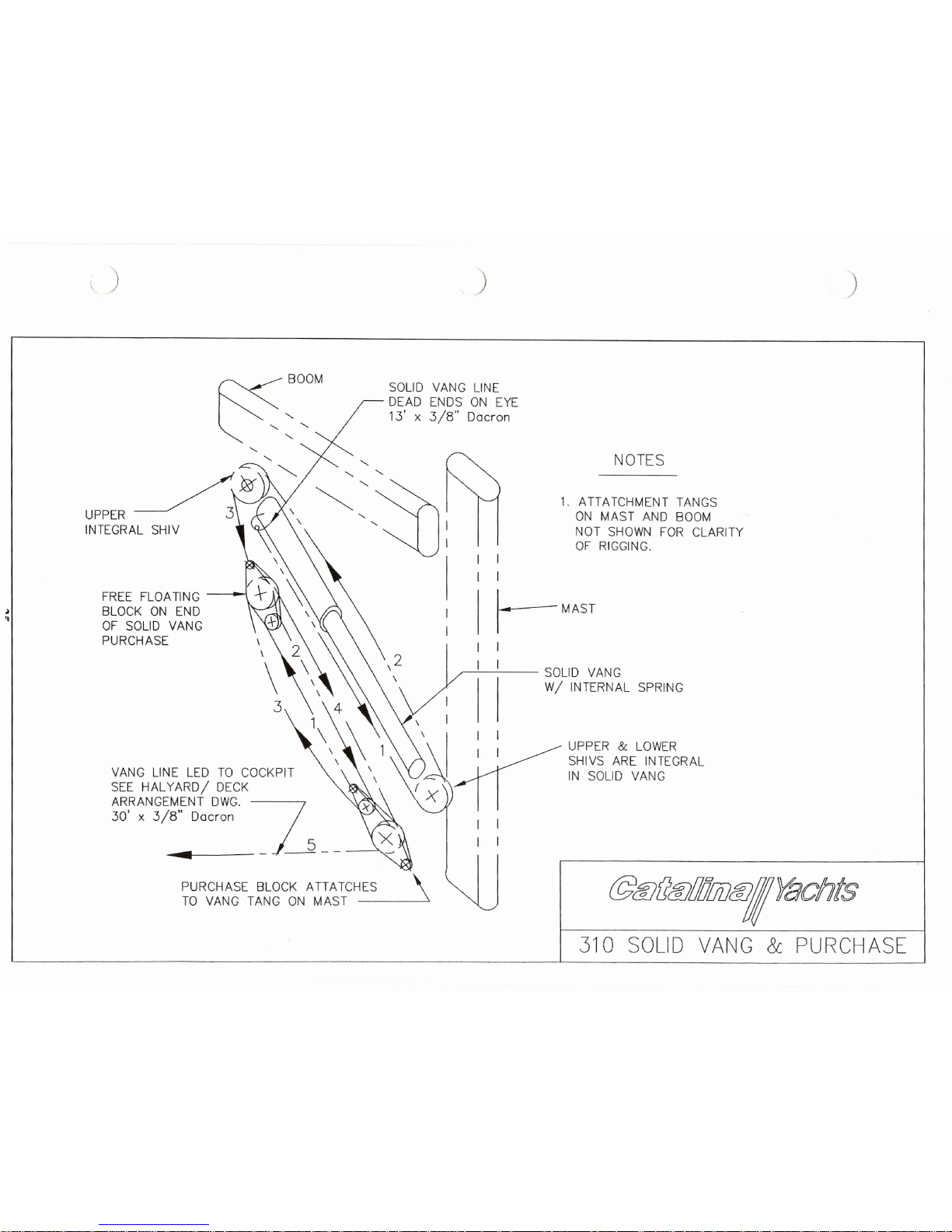
\
)
)
)
FREE FLOATING
BLOCK ON END
OF SOLID VANG
PURCHASE
VANG LINE LED TO COCKPIT
SEE HALYARD/ DECK
ARRANGEMENT DWG. ~
30' x 3/8" Dacron
5
..
- ----
PURCHASE BLOCK ATTATCHES
TO VANG TANG ON MAST
SOLID VANG LINE
DEAD ENDS ON EYE
13'x3/8" Dacron
I
I
j---MAST
I
-r--,---I_- SOLI0 VANG
W/ INTERNAL SPRING
\
NOTES
1. ATTATCHMENT TANGS
ON MAST AND BOOM
NOT SHOWN FOR CLARITY
OF RIGGING.
UPPER&LOWER
SHIVS ARE INTEGRAL
IN SOLID VANG
310 SOLID VANG
&
PURCHASE
Page 29
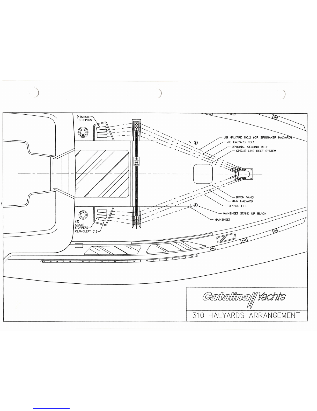
,
)
)
(4) SINGLE
STOPPERS
o
<;
<>:
I ; ; ~"-.-~ , ~
JIB HALYARD NO.2 (OR SPINNAKER HALYAR
~ "'~%fV
~IB
HALYARD NO.1
<,
<,
OPTIONAL SECOND REEF
7 7
A ' ~ ;:-;:-~
SINGLE UNE REEF SYSTE"
r ---
.......
144--- - ----- - -----
-14----
---
-«:
---~---------
~
•............•..
...-
.
-- --
~
o ~----
BOO"
VANG
___ ~ MAIN HALYARD
(3) - _ - :::::: - - ~
TOPPING LIFT
~LE --' ~
STOPPms - WJNSHEEf SfAND UP BlAC"
ClA"CLEAT (I) "NNSHEEf
@&J(]&JIJ;J!iD&JIJitJchts
310 HALYARDS ARRANGEMENT
Page 30

)
,
)
)
~~
)v
~~<;)
~<v'
#-S'
CJ~~
')0
1--
~
-l
o~ /
0J
~
R-
<v«!- \
~ ~
)v "
t
R-~
~<v'
-.0<{
g,S'
~<v,
~~ g,S'
CJ~ ~
~~
(j
=Ee£~~!.
@ClJ(/ClJ/JiJ!7iJCi1,YaChts
OR DUPUQJED, rN MiOlE OR t4 PNU, FOR
AHf
PURPOSES WHATSOEVER, WIlHOUT THE PRIOR WRIT-
n:H PERMISSION
fI!
CATAI.IttAo
YACHTS. 21200
~~~:~~.~~~7'~ ~
--i
~::~s:S:a?l1~!
310 SHROUD RIGGING
INTERMEO
UPR
Page 31
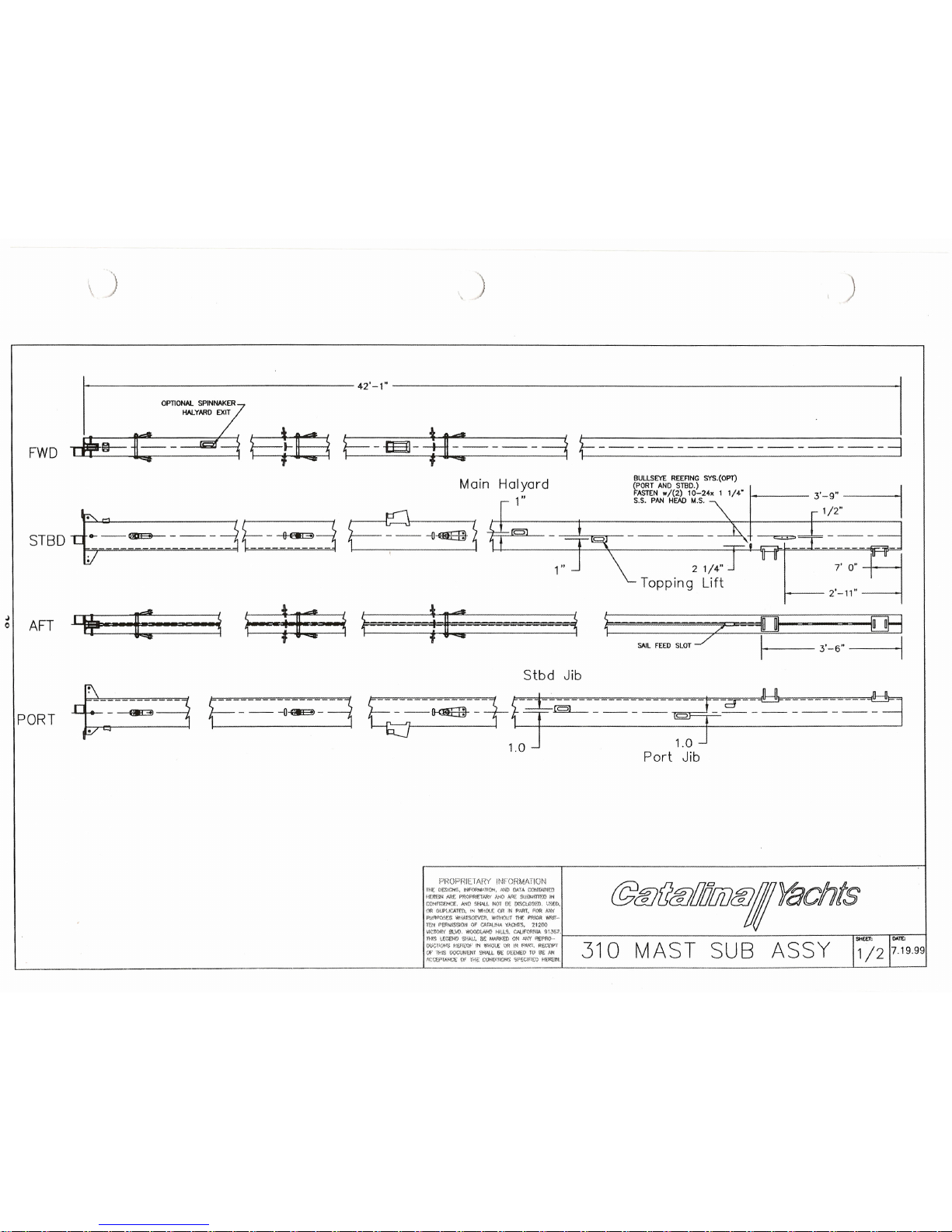
\
)
)
)
nl[
~~;~~I~~~.~~.I~~~O()~~'~~'r.n
@~t1~WCJ7fJiJ~rII~(Qn,~s
HmON Mr.. PR¢f">Rlr.TARY
"-"40
A~
SuHtJ!Tl"F..(')
Iii
0 0 0
~N~;;~0:1~~~Nr\~~.~~
~~~!~:;(),
P-J;":l{$(y,('S
WliA1'S<X:"«:r~,
wn'Hour THf. PRIOR WRrr·~
TEN PE!'<llISSlOti ()F
CArtU~
YJ.CH1'S. 21200
~~c-!6'SH~~~=-
~~~~~7·f-
--------------------------";;;<';;:--T.i0A;;'re;i.:--l
WCI'O>l'. "'''''.'' IN 'M<Cl£ "" IN
"",r.
"Ii,,,wr 310M AS T SUB ASS Y
~. THIS Q<X;t/Nu.:r ~M..t SE
()~iJ(£Q
fQ
BE ~
A(W~UN(.'((WfHi t,'OtlQ!1l0HS
'M'£Cirlt:lJ
H\':R£:."I't
J
e
42'-,· .
I
F-~-
1£--- -
---=i
f-- -- -- -- -- -- --
--=]
~".§
HALYARD EXIT
JF@
b-~
f=l-E
FWD
STBD ~
"-alE>- - - -
:1E-~3
.
E-~~l
BULL5EYE REEFING SY5.(OPT)
---l
(PORT AND 5TBD.) 2' 1 1/4"
I
3'-9"
FASTEN
w/(2) 10- .•
x
5.5. PAN HEAD M.S. ~
1/2"
Main Halyard
1"
1"
2 1/4"
Topping Lift
c:::::::c>~-----
:=
~r~] - --- - --- -
~
u
7' 0"
I
2'-1'"
AFT
llF·
ue· ~
~ ~E ~~
~E ~
~ 2 []
fOR
SAIL
FEED
SLOT::;: I
3'- 6"
I
{~~3
E---o~-3
Stbd Jib
E~~-t9==-----tf~-~----~
1.0 1.0
Port Jib
PORT
7.19.99
Page 32

\
)
)
UPPER SHROUDS
-9!F-~-,
INTERMEDIATE SHROUDS
UPPER SPREADERS
LOWER SHROUDS
LOWER SPREADERS
SPREADERS TIP DETAIL
SEIZING
WIRE
HOLES
HALYARD EXIT LOCATION
SCALE: NONE
PORT JIB
STARBOARD.JIB (OPL)
MAST WIRING
COLOR CODE
I
i
~
~ ~i
i
I;~~
Iil
~;j ~~
i
CONNECT WIRES AS ~
I?lflIIII
SHOWN IN OOTTED UNES
!\
TIT
'-....J \
I
I I
ii
~r'
Ii i!
r:! ~
0
:::l
i
m ~ ~
Tilt!::I~;~~~N.I~~~O~~·~~~~rn
@(f}t1~WC17[jfJ~'~lCAn1:.S
tl£ftBNM£PRCPRlr.TARY A"IO ~~
SlJ8MO'T'El'l
lti
0 0 0
~N~~~~!~~~~t\:;t~~~~~~
~;~D<
PUftP0:5r.s WliAl'SOMR, ~11'HOUT rnr. PR10R
~.P
1tH P'£FN.iSsroN ¢F
CAf.t..UN.I.
YACNTS. 21200
:;O~~~;.~~~:~.
!tU::;:~~~('I- -r=_=-_-,,",,_=_-I
""ef'''''"
HERtUf,"",' "'<iCe( Of' IN
".<I{", R!!.(.'El.r
310M AST SUB ASS Y
Of' TH~ Q(X..'tItJI:14f
SHAU..
(-i[.:
D~t.\fti.V 10 BE
m
,.l,{:t.'H~fAN(~
m' no;:
(,x~unONS $P£ClY1EOt1t:.Ratt
SPINNAKER.(OPT.) --
41/2"
UPPERS
5/B"
TYPICAL
LOWERS
r
I
1
0
10
I
L
INTERMEDIATE <I<
UPPER
SHROUDS
TOPPING UFT
7.19.99
Page 33
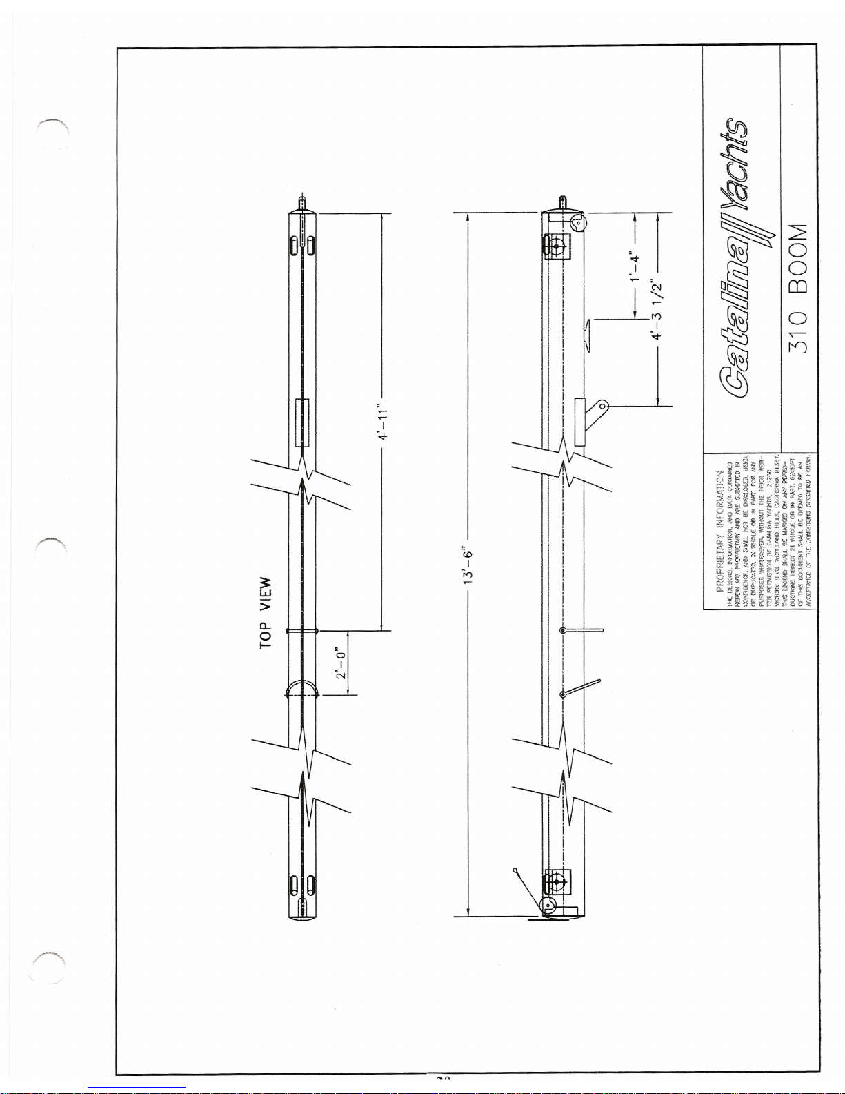
3:
w
>
a..
o
I-
I
':.t
c.o
I
'h
~
~
~
~
2
0
~~
o§§
0
OJ
~
0
I
':.t
~
~
n
~
Page 34

\
)
)
MINI-BLOCK
w/
BECKET
~I
.
LONG D-SHACKLE
PLASTIC
COATED WIRE
SWIVEL COUPLER
CLEAT
1/4" DACRON LINE
@fiJ(}fiJlJilfii)'1I
Yachts
310 OUTHAUL ASSEMBLt.6
Page 35

ELECTRICAL DC 12 VOLT:
BATTERIES:
Your electrical system is powered by 2 marine grade, 12 volt, deep cycle batteries. Attention
should be given to maintaining the proper level of distilled water. Do not overfill. The batteries
are located under the settee, forward of the galley.
The batteries are provided with a tie down to prevent tipping over at extreme angles of heel. Be
sure these tie downs are fastened securely.
With proper care, the batteries installed in your Catalina will provide long .and satisfactory
service. Proper care is not difficult if a few basic points are kept in mind.
Your batteries should be checked periodically for any cracks or breaks in the case or cover and
any cracks in the sealing compound. If there is any damage, the battery should be replaces at
once.
WARNING:
The electrolyte in a battery is a solution of sulfuric acid. If any should enter the
eyes, rinse immediately with large amounts of fresh water and seek medical
attention. Electrolyte spilled on skin should be rinsed well with fresh water
also. Even a small amount of electrolyte spilled on clothing will destroy the
clothing.
ELECTROLYTE LEVEL:
The electrolyte level in a battery should never be allowed to fall low enough to expose the plates.
This not only results in a loss of battery capacity while the battery is low, but will cause hardening
of the active material on the battery plates. This will result in a permanent loss of battery
capacity.
CAUTION: Use only pure distilled water to replenish electrolyte levels. The water from
many city water supply systems is unsatisfactory for battery use.
CHARGING THE BATTERY:
Before adding water, a hydrometer reading of the battery should be taken. If the reading shows
the battery to be above 1.225 specific gravity, the battery has a sufficient charge. If the reading is
below 1.225, the battery should be removed for bench charge.
Once charged, the battery should have a specific gravity of at least 1.260. If this cannot be
reached, the battery should be inspected by a battery supplier.
The batteries should be checked often to ensure that they do not run down. Check that all battery
cells keep an even fluid level and that the fluid is about 3/8" above the top of the separators.
If one or two cells have lower fluid levels, it is a good indicator that something is wrong with the
battery, and it should be checked.
DISCHARGED STATE:
Leaving a battery in a discharged state for any length of time can also result in a permanent loss of
capacity for the battery. Since it will freeze at relatively low temperatures, leaving it in the cold
weather can destroy the battery.
32
Page 36
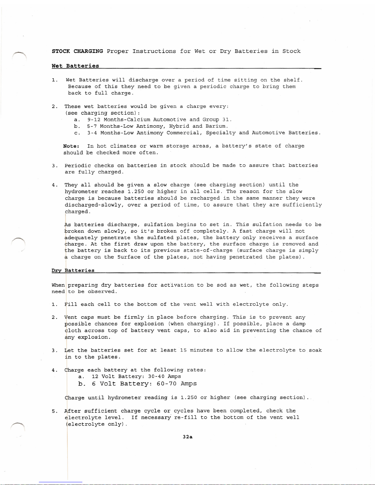
STOCK CHARGING Proper Instructions for Wet or Dry Batteries in Stock
Wet Batteries
1. Wet Batteries will discharge over a period of time sitting on the shelf.
Because of this they need to be given a periodic charge to bring them
back to full charge.
2. These wet batteries would be given a charge every:
(see charging section) :
a. 9-12 Months-Calcium Automotive and Group 31.
b. 5-7 Months-Low Antimony, Hybrid and Barium.
c. 3-4 Months-Low Antimony Commercial, Specialty and Automotive Batteries.
Note: In hot climates or warm storage areas, a battery's state of charge
should be checked more often.
3. Periodic checks on batteries in stock should be made to assure that batteries
are fully charged.
4. They all should be given a slow charge (see charging section) until the
hydrometer reaches 1.250 or higher in all cells. The reason for the slow
charge is because batteries should be recharged in the same manner they were
discharged-slowly, over a period of time, to assure that they are sufficiently
pharged.
As batteries discharge, sulfation begins to set in. This sulfation needs to be
broken down slowly, so it's broken off completely. A fast charge will not
adequately penetrate the sulfated plates, the battery only receives a surface
charge. At the first draw upon the battery, the surface charge is removed and
the battery is back to its previous state-of-charge (surface charge is simply
a charge on the Surface of the plates, not having penetrated the plates) .
Dry Batteries
When preparing dry batteries for activation to be sod as wet, the following steps
need to be observed.
1. Fill each cell to the bottom of the vent well with electrolyte only.
2. Vent caps must be firmly in place before charging. This is to prevent any
possible chances for explosion (when charging). If possible, place a damp
cloth across top of battery vent caps, to also aid in preventing the chance of
~ny explosion.
3. Let,the batteries set for at least 15 minutes to allow the electrolyte to soak
in to the plates.
4. Charge each batterY at the following rates:
a. 12 Volt Battery: 30-40 Amps
b. 6 Volt Battery: 60-70 Amps
Charge until hydrometer reading is 1.250 or higher (see charging section) .
5. After sufficient charge cycle or cycles have been completed, check the
dlectrolyte level. If necessary re-fill to the bottom of the vent well
(electrolyte only) .
32a
Page 37
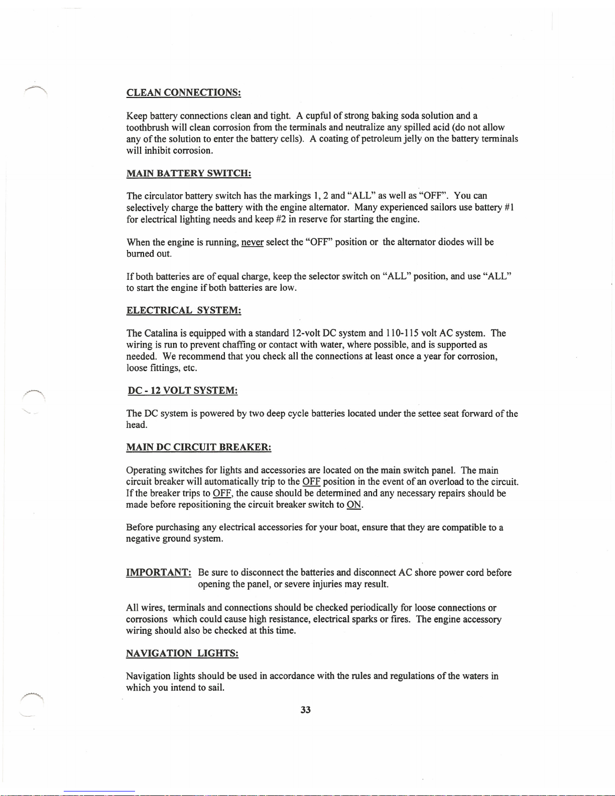
CLEAN CONNECTIONS:
Keep battery connections clean and tight. A cupful of strong baking soda solution and a
toothbrush will clean corrosion from the terminals and neutralize any spilled acid (do not allow
any of the solution to enter the battery cells). A coating of petroleum jelly on the battery terminals
will inhibit corrosion.
MAIN BATTERY SWITCH:
The circulator battery switch has the markings 1,2 and "ALL" as well as "OFF". You can
selectively charge the battery with the engine alternator. Many experienced sailors use battery # 1
for electrical lighting needs and keep #2 in reserve for starting the engine.
When the engine is running, never select the "OFF" position or the alternator diodes will be
burned out.
If both batteries are of equal charge, keep the selector switch on "ALL" position, and use "ALL"
to start the engine if both batteries are low.
ELECTRICAL SYSTEM:
The Catalina is equipped with a standard 12-volt DC system and 110-115 volt AC system. The
wiring is run to prevent chaffing or contact with water, where possible, and is supported as
needed. We recommend that you check all the connections at least once a year for corrosion,
loose fittings, etc.
DC - 12 VOLT SYSTEM:
The DC system is powered by two deep cycle batteries located under the settee seat forward of the
head.
MAIN DC CIRCUIT BREAKER:
Operating switches for lights and accessories are located on the main switch panel. The main
circuit breaker will automatically trip to the OFF position in the event of an overload to the circuit.
If the breaker trips to OFF, the cause should be determined and any necessary repairs should be
made before repositioning the circuit breaker switch to ON.
Before purchasing any electrical accessories for your boat, ensure that they are compatible to a
negative ground system.
IMPORTANT: Be sure to disconnect the batteries and disconnect AC shore power cord before
opening the panel, or severe injuries may result.
All wires, terminals and connections should be checked periodically for loose connections or
corrosions which could cause high resistance, electrical sparks or fires. The engine accessory
wiring should also be checked at this time.
NAVIGATION LIGHTS:
Navigation lights should be used in accordance with the rules and regulations of the waters in
which you intend to sail.
33
Page 38
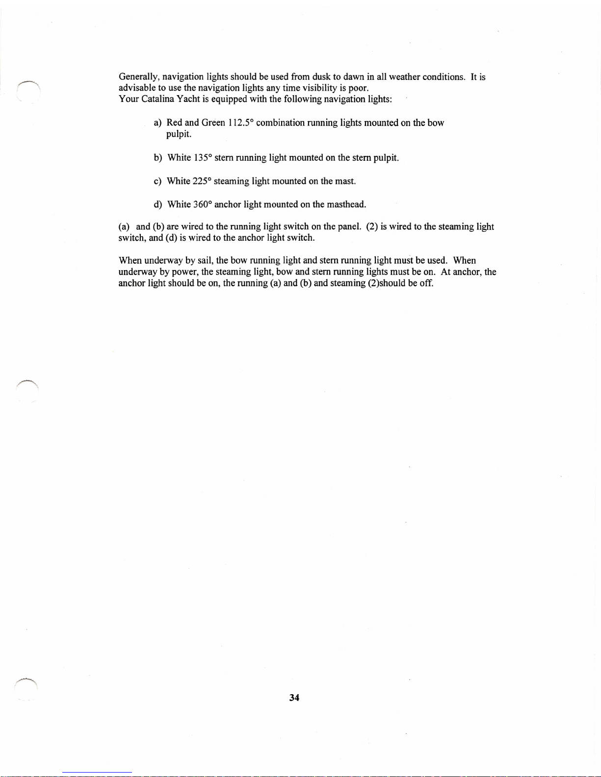
Generally, navigation lights should be used from dusk to dawn in all weather conditions. It is
advisable to use the navigation lights any time visibility is poor.
Your Catalina Yacht is equipped with the following navigation lights:
a) Red and Green 112.50combination running lights mounted on the bow
pulpit.
b) White 1350stem running light mounted on the stem pulpit.
c) White 2250steaming light mounted on the mast.
d) White 3600anchor light mounted on the masthead.
(a) and (b) are wired to the running light switch on the panel. (2) is wired to the steaming light
switch, and (d) is wired to the anchor light switch.
When underway by sail, the bow running light and stem running light must be used. When
underway by power, the steaming light, bow and stem running lights must be on. At anchor, the
anchor light should be on, the running (a) and (b) and steaming (2)should be off.
34
Page 39

)
REV
I
DESCRIPTION
o
UPDATED UPON ARRWAL. ATfLPLANT
12
2
4
NOTES: (UNLESS OTHERWISE SPECIFIED)
ill
MULTIPLE CONDUCTOR CABLE.
mAC WIRING SHOWN ON DWG. 310-73001,
115VAC WIRING DIAGRAM W/CHARGER
&,
SECURED TO BOTTOM SURFACE OF DECK.
&
SEE DWG #310-72004, PWR DIST, 12VDC
&
SEE DWG #310-72003, WIRING, MAST
~=-'_~?_::;"._?~.~_~_:.~
"~~¥
~/>td7ts ~_
- - - xWx ; !8:?i.s
:5 24. 00
31720013
?'E:.7:~"'::';Z
DO~:~~~tN
ELECTRICAL PLAN, DC
0 Vi
CATALINA 310
31G-720::';O-O
6
V>
V>
:;)
£D
U
o
21
2
3
WINDLASS BREAKER
80 AMP
A
ELECTRIC SERVICE
PANEL
I
)
DATE
APPROVAL
3/2~!OO
Page 40
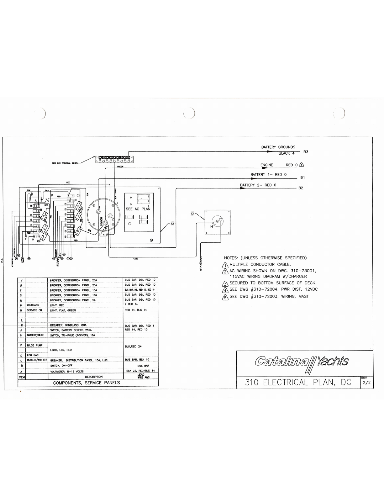
)
)
)
BATTERY GROUNDS
_.,. ~~·~~ol
BLACK 4 B3
-
ENGINE RED 0&
~'
1'\
v
U
T
S
R
p
LMNiilASS
N
I SERVicE:
ON
l
BATTERY 1- RED 0
B1
••••
B2
BREAKER. DISTRIBUTION PANEL. 20A
....
.
"
"
.
BREAKER. OISTRIBUTION PANEl. 251.
....
~--.
..~...
,.,.
.-
._-----,
..
BREAKER. DISTRIBUTION PANEL. 151.
...
"
,
"
'
,.,
-
",.,,,
.
BREAKER. DISTRIBUTION PANEl. 1OA
V'~"""""""""'" •••••••••• "•.•.• "..... • _
'···"w··~·'·....
BRf:lJ(~'.lll~I.BUTlON ..PAI'I~' 51.
UGHT.
RED
UGfIT,f'L,o'!, G.R~.E:tI
t!)
I
III
I
SEE AC PLAN
liil
ILjJ
[Iii
o
@
:;2'
•••••
BATTERY 2- RED 0
i.~:-,
1°
'-;-1
~J
BUS BAR. DBl RED 10
BUS BAR. DBl RED 10
BUS 8M,talID) 10. lID) 10
BUS BAR. DBl RED 10
BUS BAR. DBl REO 10
2 BLK 14
REO 14. BLK 14
--;~t~I'~~~~_T;~~S~~~t:~~-=~~~-==,~=,:~~J:!~:~'~~~~;~m,.L
.!:,..
J~.!'.~,-.--
BLK.RED
24
I,'~,"'1
~twrrl.rrRt;~~;--;;;;;-;;;,;;;·'
PANa-;;,-~··-·-'---I ••
Bus··BAR:·BLK·
10
,~, .. ........,..,........."~,,....,_.~~ ~~~ ."' ,.__._,..__.__v._._,,~'''_~,~.,,·,~,=-- __
A.W'·_. _.~
B SWlTCH. ON-OFF
...
~
",
,
,..
"
, ,
--,..
-..-.-.~",.,.,
,
'''
".".
A
I
COMPONENTS, SERVICE PANELS ,
---------------_._--_._-------------
ITEM
lIGHT.
LEO. REO
VOLTMETER. 8-18 VOLTS
DESCRIPTION
BUS BAR
BLK 22. REO/BLK 14
LEAD
WIRE
",we
NOTES: (UNLESS OTHERWISESPECIFIED)
ill
MULTIPLE CONDUCTOR CABLE.
mAC WIRING SHOWN ON DWG. 310-73001.
115VAC WIRING DIAGRAM W/CHARGER
&
SECURED TO BonOM SURFACE OF DECK,
ill
SEE OWG #310-72004, PWR OIST. 12VDC
&
SEE OWG #310-72003. WIRING, MAST
VJ
o
=u
c
'i
@1ff}(l1ff}!lJ!liJIff}IYachtS
SNttT.
310 ELECTRICAL PLAN, DC
2/2
Page 41
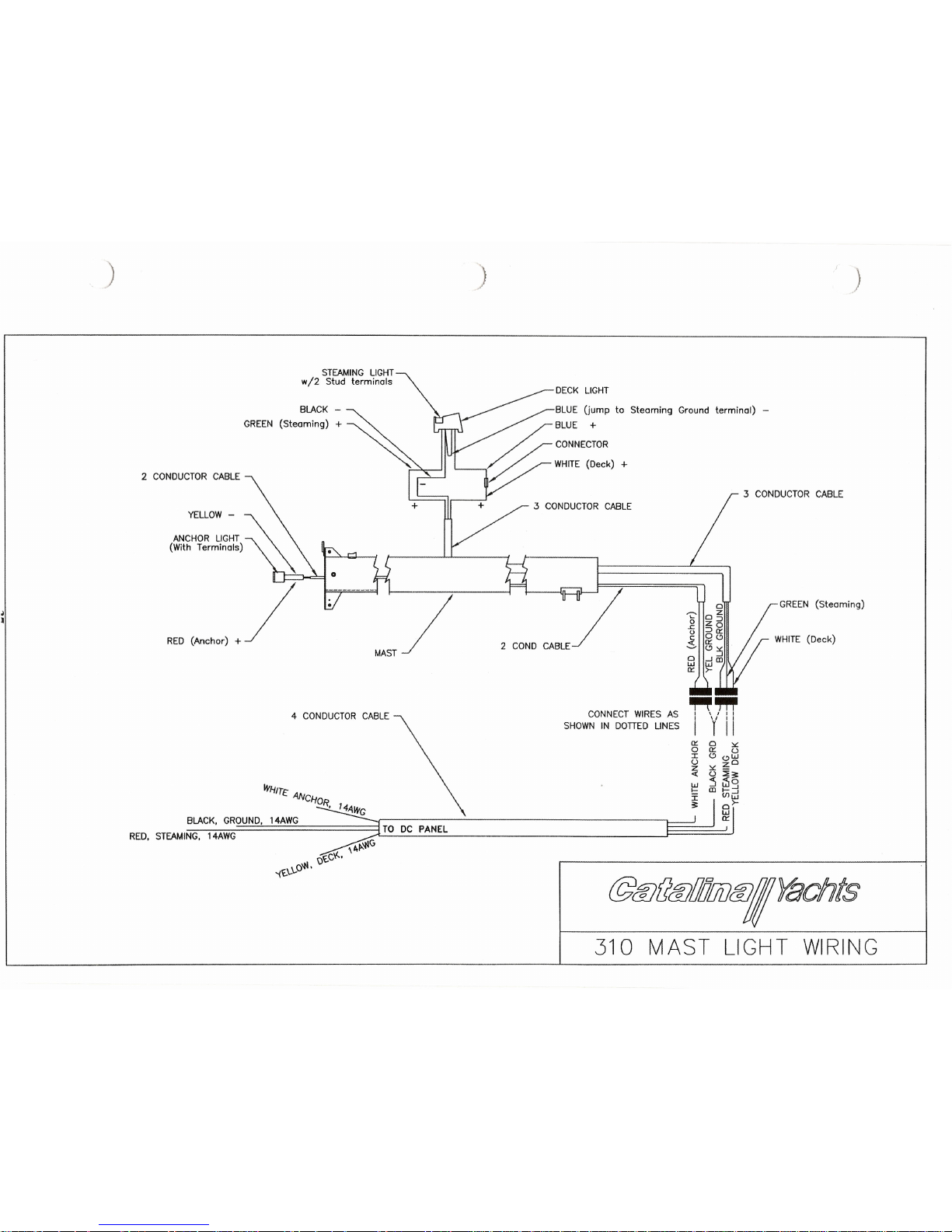
)
)
STEAMING LIGHT
w/2 Stud terminals
GREEN
BLUE (jump to Steaming Ground terminal) -
~
BLUE +
CONNECTOR
~ WHiTt (Deck)
+
2 CONDUCTOR CABLE
3 CONDUCTOR CABLE
3 CONDUCTOR CABLE
GREEN (Steaming)
MAST/
"2
o
s:
o
~
WHITE (Deck)
4 CONDUCTOR CABLE
CONNECT WIRES AS
SHOWN IN DOTTED LINES
~'"
I \II I
I Y II
0::
o
I
U
Z
-c
WHIT~ AN
CHOR
, 14A~
BLACK, GROUND, 14AWG G
RED, STEAMING, 14AWG ~....:.T..:..O....:D:.:C:.....:..P=AN:.::E::.::L~
J=====~~
_ \brf>.~G
Q't-Cv-'.
'i't-\..\..O~'
@@fl@I!I!!lDtf/Yachts
310 MAST LIGHT WIRING
Page 42

ELECTRICAL AC -110-115 VOLT SYSTEM:
The IIOV AC power system depends upon the boat being connected to llOV-30 amp shore
power connector. The factory option offers a 50' shore power cable which should be plugged into
the llOV inlet on he boat (located on the transom) and into the shore power connector on the
dock.
IMPORTANT: TO MINIMIZE SHOCK AND FIRE HAZARDS:
1. Turn off the boat's shore connection switch before connecting or
disconnecting the shore power cable.
2. Connect the shore power cable at the boat first.
3. If the polarity warning indicator is activated, disconnect the cable
immediately.
4. Disconnect the shore power cable at the shore outlet first.
5. Close the shore power inlet cover tightly.
6. DO NOT ALTER THE SHORE POWER CABLE CONNECTORS IN
ANY WAY. SEVERE INJURY MAY OCCUR.
Care should be taken to support the shore power cable at both ends to allow sufficient slack to
avoid pulling. Remember to allow for the tide.
The master breaker switch is 30 amp, two pole type, located in the port stem locker. There are
five (5) IIOV outlets. Be certain that all 110 volt appliances, other than lamps, have an adequate
grounding connector. Wet feet or moist atmosphere increases the potential shock hazard.
There is a reverse polarity indicator on the panel. With all switches off, attach the power cable to
the inlet. Next, attach the power cable to the dock outlet. If the reverse polarity light comes on,
DISCONNECT THE CORD IMMEDIATELY! This indicates a reverse polarity situation which
is very dangerous.
WARNING:
Do not open the electrical panel for any purpose with the shore power cable
connected to the dock. 110 volt wiring is exposed when the panel is open.
Contact with the 110 volt wiring can cause electrocution. Electricity is
dangerous. Even when safety devices are present, handle with care and use
reasonable caution.
GROUND FAULT INTERRUPTER:
G.F.I. receptacles are designed to provide protection against electrical shock hazards due to
line-to-ground faults. Although the G.F.I. receptacle does not limit the magnitude ofthe fault
current, and therefore cannot prevent electrical shock, it does limit the duration of the shock to
a period considered safe for normal healthy persons. G.F.I. receptacles will provide protection
against ground faults only. They will not protect against overload or short circuits. There is no
known device that will guard against the electric shock hazard resulting from contact with both
the "hot" and neutral wires of the electrical circuit.
The llOV AC outlets in the Catalina Yacht are protected by the G.F.I. receptacle. If there is a
power failure which does not affect the fuse or breaker serving these outlets, unplug all cord-
38
Page 43
connected appliances from the protected outlets, unplug all cord-connected appliances from the
protected outlets and restore power by pressing the red RESET button on the receptacle. Push the
RESET back in and reconnect the appliances one at a time. Any defective appliance will trip the
button and should be repaired at once.
If the appliances are all disconnected, and the RESET button will not stay in, cal a qualified
electrician. If the RESET button does not pop out when the blue TEST button is pressed,
PROTECTION IS LOST. Do not use any of the outlets and call a qualified electrician
immediately.
IMPORTANT: Your Ground Fault Interrupter Circuit should be tested regularly.
Use the following steps:
1. Push the blue TEST button. The red RESET button should pop out. Power
is now out at that outlet indicating that the circuit is operating properly.
2. If the button does not pop out when testing, do not use that outlet.
Protection is lost and a qualified electrician should be called.
3. To restore power, push the RESET button.
PREVENT ATIVE MAINTENANCE:
This consists of periodic inspection and protection against any damage created by the elements.
Electrical systems are adversely affected by moisture and a salt-air environment.
The system can be protected by the application of aerosol sprays such as WD-40 or CRe. All
wire harnesses and connections should be checked periodically to ensure that fastenings are
secured and that everything is clean with no sign of damage or corrosion. It is extremely
important that all connections be kept clean.
WARNING:
Do not perform any maintenance or repair on a live circuit. Do not turn the
main DC switch off while the engine is running. This could cause damage to the
alternator.
39
Page 44
--_._
.
-----------
.........-~~!6
---
--,~
I1111
C~)/
"'"
G:)
~J
0
<..:>
0
0'60
000
000
000
1--'
~
~ ~
~~~
~~~
~~~
~~~
I
&:
«0
-c
N~~
N~~
I
~O
000
0_0
-
-
---
-
-
---
---
..'CD
I
I
~
:5 z
Z:5~
z:5~
Z~:><:
Z~:><:
J:
COo::
13co~
o::COJ:
o::J:...J
O::J:...J
&
I
Z
I
~
• 0
o .~
0~CO
0~CO
I
:5
I
a::
ci
a::
I~
I
""
w
<5
<5
I
a::
0::
0
CO
w
a::
G:
G:
2;
-c
0
0
ti
::z::
I
I
,,--....,
<..J
t;i
t;i
----------1 W
I
J:
~--~
::;;
>-
0
0::
a::
...J
...J
(/)
W
W
~
I-
Z
~
~
=>
=>
I
C2
0
0
I--
w
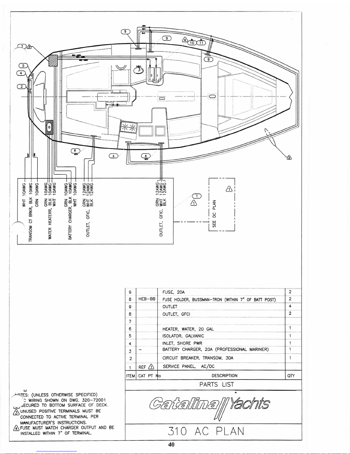
~S: (UNLESS OTHERWISE SPECIFIED)
:: WIRING SHOWN ON DWG. 320-72001
~ECURED TO BOnOM SURFACE OF DECK.
&
UNUSED POSITIVE TERMINALS MUST BE
CONNECTED TO ACTIVE TERMINAL PER
MlllNUFACTURER'S INSTRUCTIONS.
&
FUSE MUST MATCH CHARGER OUTPUT AND BE
INSTALLED WITHIN7"OF TERMINAL.
2
9
3
FUSE. 20A
~ .._ ....H.....
E._..
B_...-.~B _ ~~~~~.LDE~. BUSSMAN-!RON (WITHIN
7:.
OF BATT POST)
9 OUTLET
.,."
,..,
"
,
..
"'''"
.
8 OUTLET. GFCI
." "_"',_ v••y· .~'.•_,~
'~44'
7
6
5
2
4
2
- ...-..-~....-.-.-..--.-.-- ...•.-1----1
4
3
2
....HE!-TE~,'II' "'TER.
?Cl
C;",L
ISOLATOR. GALVANIC
INLET. SHORE PWR
BATIERYCHARGER.2()A·· (PROFEssiONAL. MARINER)
.~••••••• ~... •. ••••• • ••• -~ .••• ~... ••••• '¥' ••• y'" .~••• ~.- ••- •••~,- •• ~•••••• --.- ••••-- •.•
CIRCUIT BREAKER. TRANSOM. 30A
_'·",."_·,_,.~_",~.,~.".'",.v.,~·",,,·.,~,·.·' _
SERVICE PANEL. AC/DC
REF
&
ITEM I CAT PT ['10
DESCRIPTION
QTY
PARTS LIST
@@(J@!l!l!7iJ@I
Yacht
s
310 AC PLAN
40
 Loading...