

Page 1
STANDARD HEATER APPLICATIONS
INSTALLATION & OPERATION INSTRUCTIONS
WARNING: Improper installation, adjustment,
alteration, excessive vibration, service or maintenance
can cause property damage, injury or death. Read the
installation, operating and maintenance instructions
thoroughly before installation or servicing this equipment.
Æ
BKI
1418
The Cata-Dyne™ heater can be used in all
industrial indoor locations where a source of
infrared radiant heat is required, providing
adequate ventilation is available.
CERTIFICATION
Model WX (Series X) & MKII Cata-Dyne™
Explosion-proof, flameless infrared catalytic gas
heaters are certied by the Canadian Standards
Association (CSA) for use in Class I, Divisions 1
and 2, Group D hazardous (classied) locations
and FM Approvals, for use in Class I, Division
1, Group D hazardous (classied) locations,
temperature code T2C at an ambient temperature
of 40ºC (104ºF). WXS models are suitable for
Class I, Division I, Group D, temperature code
T2B at an ambient temperature of 40°C (104°F).
Models WX & MKII are certied ATEX/CE for use
in gas environments, Category 2, Zone 1 & 2,
Group IIA.
The Model BX (Series G) Cata-Dyne™ heater
is certied by CSA and FM for use in general
industrial non-hazardous locations. Models listed
are certied for industrial use only, for either
natural gas or propane gas. CSA approved models
are equipped for high altitudes: 0 - 4,500 ft. (0-
1,370 m) above sea level.
INSTALLATION
To ensure maximum efciency of your Cata-
Dyne™ heater, it should be installed with the
heating surface positioned plus or minus 45° from
the vertical plane at a height of no more than
8 ft. (2.44 m). All heaters must be installed in
accordance with the latest revisions of the codes
described in table 4 and in accordance with any
local codes and regulations. Before installing the
heater, all information on the heater nameplate
must be carefully reviewed. The nameplate lists all
the fuel and electrical requirements for the heater.
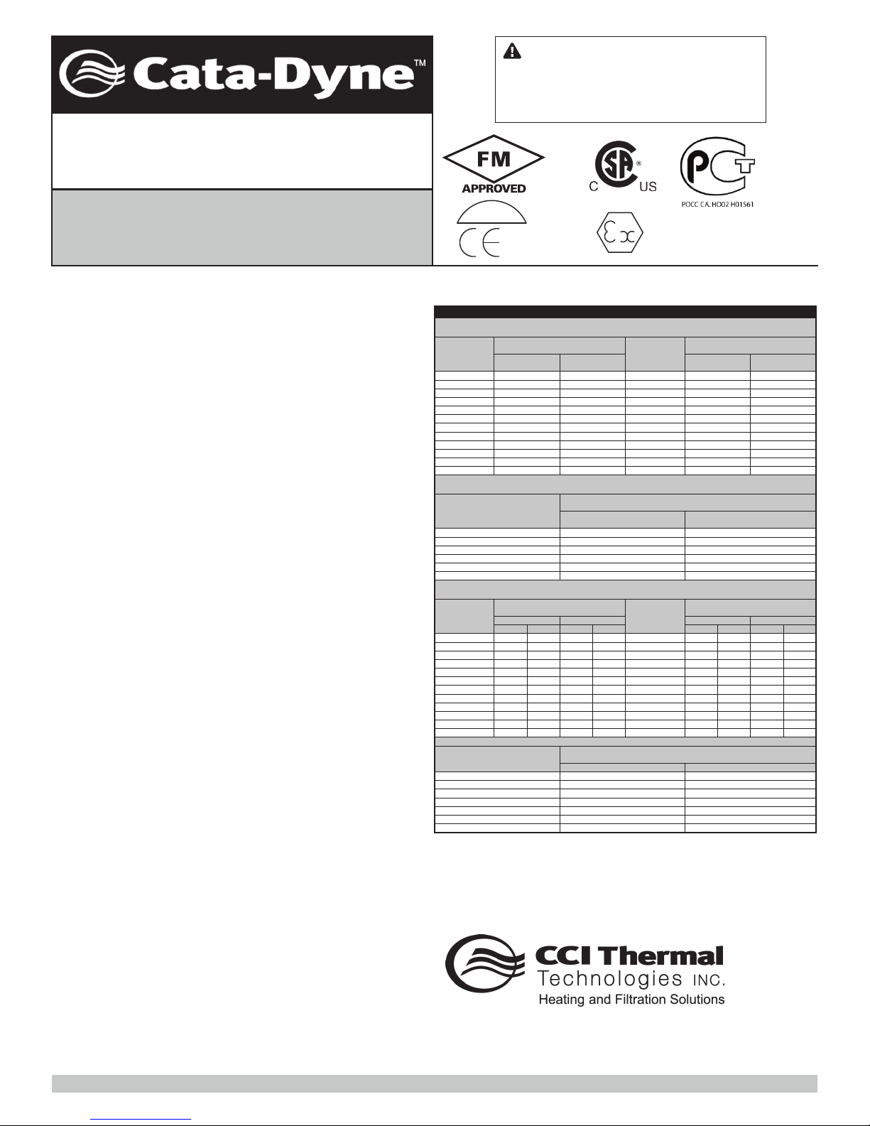
Table 1
Cata-Dyne™ Heater - Models Available - CSA Only
Approved for use in Class I, Division 1 and 2, Group D hazardous (classified) locations by both FM and CSA T-Code T2C @ 40°C Ambient
Model Number Model Number
WX 6 x 6
WX 6 x 12
WX 6 x 24
WX 6 x 60
WX 8 x 8
WX 10 x 12
WX 12 x 12
WX 12 x 24
WX 12 x 36
WX 12 x 48
WX 12 x 60
WX 12 x 72
Approved for use in Class I, Division 1 and 2, Group D hazardous (classified) locations by both FM and CSA T-Code T2C @ 40°C Ambient
Model Number
BX 6 x 6
BX 6 x 12
BX 6 x 24
BX 6 x 60
BX 8 x 8
BX 10 x 12
BX 12 x 12
BX 12 x 24
BX 12 x 36
BX 12 x 48
BX 12 x 60
BX 12 x 72 30,000 36,000 8.786
The WX Series Cata-Dyne™ features an improved efciency catalyst pad that required nearly 33%
less fuel to generate the same value as our BX Series Cata-Dyne™ heater.
Specifications (Btu/hr Input Ratings)
For Both Natural and Propane Gas
Max. Btu/hr
1,250
2,500
5,000
12,500
2,222
4,167
5,000
10,000
15,000
20,000
25,000
30,000
Model Number
MKII 12x12
MKII 12x24
MKII 18x24
MKII 18x48
MKII 24x24
MKII 24x48
Approved for use in general industrial non-hazardous locations by both FM and CSA
Specifications (Btu/hr Input Ratings)
For Both Natural and Propane Gas
Max. Btu/hr
LPG NAT LPG NAT LPG
1,250 1,500 0.366 0.439 15,000
2,500 3,000
5,000 6,000 1.464 1.757 22,500 27,000 6.590 7.908
12,500
15,000 3.661 4.393 30,000
2,222 2,667 0.651 0.781
4,167 5,000 1.220 1.464 45,000 54,000 13.179
6,000
5,000
10,000 12,000 2.929 3.514
15,000 18,000
20,000 24,000 5.857 7.029 40,000
25,000 30,000 7.322 8.786
Approved for use in Class I, Division 1, Group D hazardous (classified) locations by FM, T-code T2B at 40°C ambient
Model Number
WXS 6 x 6
WXS 6 x 12
WXS 6 x 24
WXS 8 x 8
WXS 12 x 12
WXS 12 x 24
5918 Roper Road, Edmonton, Alberta, Canada T6B 3E1
Telephone: (780) 466-3178 Fax: (780) 468-5904
WX Model (Series X)
Max. kW
0.366
0.732
1.464
3.661
0.651
1.220
1.464
2.929
4.393
5.857
7.322
8.786
MK II Model (Series X)
BX Model (Series G)
Max. kW
LPG
0.732
1.464 1.757
4.393 5.272 30,000 36,000
WX 18 x 24
WX 18 x 30
WX 18 x 36
WX 18 x 48
WX 18 x 60
WX 18 x 72
WX 24 x 24
WX 24 x 30
WX 24 x 36
WX 24 x 48
WX 24 x 60
WX 24 x 72
Specifications (Btu/hr Input Ratings)
For Both Natural and Propane Gas
Max. Btu/hr
5,000
10,000
15,000
30,000
20,000
40,000
Model Number
NAT
BX 18 x 24
BX 18 x 36
BX 18 x 48
BX 18 x 60
BX 18 x 72
BX 24 x 24
BX 24 x 30
BX 24 x 36
BX 24 x 48
BX 24 x 60
10.543
Specifications (Btu/hr Input Ratings)
For Both Natural and Propane Gas
Max. Btu/hr Max. kW
1,750
3,500
7,000
3,111
5,833
7,000
14,000
Head Ofce & Factory:
Toll Free: 1-800-661-8529
Specifications (Btu/hr Input Ratings)
For Both Natural and Propane Gas
Max. Btu/hr Max. kW
15,000
18,750
22,500
30,000
37,500
45,000
25,000
30,000
40,000
50,000
60,000
Max. kW
1.464
2.929
4.393
8.786
5.857
11.715
Specifications (Btu/hr Input Ratings)
For Both Natural and Propane Gas
Max. Btu/hr Max. kW
18,000 4.393 5.272
36,000 8.786 10.543
45,000
37,500
20,000 24,000
50,000 60,000
10.983
48,000 11.715 14.058
14.644 17.572
0.513
1.025
2.050
0.911
1.708WXS 10 x 12
2.050
4.100
M20724-009 Date of Issue: July 2010
4.393
5.491
6.590
8.786
10.983
13.179
5.85720,000
7.322
8.786
11.715
14.644
17.572
NAT
5.4910.879 18,750 22,500BX 18 x 30
6.590
13.179
15.815
5.857 7.029
7.322 7.32225,000 25,000
8.786 10.543
Page 2
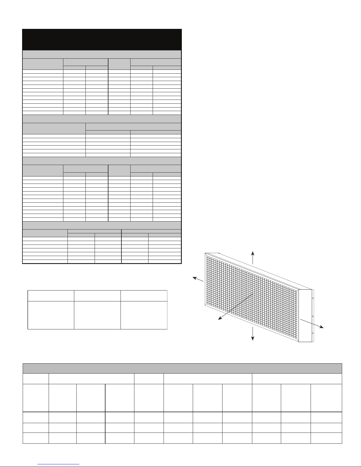
Table 2
0.366
1.220
3.661
25,000
30,000
WX 12 x 60
WX 12 x 72
4.393
WXS 6 x 6
15,000
MKII12x24
MKII24x24
Cata-Dyne™ Heater - Models Available
BX8x8
3,500
24,000
Max. Gas Input
Max. Gas Input
1,250
12,500
5.272
BX18x24
4,167
0.911
2.050
1,750
7,000
3,111
7,000
7,000
0.513
2.050
0.911
0.513
2.050
WXS 6 x 24
WXS 8 x 8
1,750
7,000
3,111
18,000
WXS 12 x 12
BX6x6
1,500
0.439
4.393
WX 6 x 6
WX 18 x 24
WX 6 x 60
WX 10 x 12
WX 12 x 36
7.322
8.786
BX Model (Series G)
2.050
BX12X24
BX12x48
12,000
WX Model (Series X)
20,000
2.929
5.857
10,000
1.025
3.514
7.029
BX18x48
BX24x24
BX24x36
BX24x72
36,000
24,000
36,000
72,000
10.543
7.029
10.543
21.087
8.786
13.179
15,000
30,000
45,000
30,000
50,000
60,000
14.644
17.572
8.786
WX 24 x 36
WX 24 x 60
WX 24 x 72
WX 18 x 48
WX 18 x 72
CATA-DYNE
TM
HEATER- MODELS AVAILABLE FOR FM ONLY
Approved for use in Class I, Division 1 and 2, Group D h azardous (classified) locations by both FM and CSA T-Code T2C @ 40°C Ambient
Model Number
WX 6 x 12
WX 6 x 24
WX 8 x 8
WX 12 x 12
WX 12 x 24
WX 12 x 48
Approved for use in Class I, Division 1 and 2, Group D h azardous (classified) locations by both FM and CSA T-Code T2C @ 40°C Ambient
Model Number
MKII12x12
MKII18x24
MKII18x48
MKII24x48
Model Number
BX6x12 3,000 0.879
BX6x24
BX10x12
BX12x12
BX12x36
BX12x60
BX12x72
Approved for use in Class I, Division 1, Group D hazardous (classified) locations by FM, T-code T2B at 40°C ambient
Model Number
WXS 6 x 12
WXS 10 x 12
WXS 12 x 24
The WX Series Cata-Dyne™ features an improved efciency catalyst pad that required nearly 20%
less fuel to generate the same value as our BX Series Cata-Dyne™ heater.
Specifications (Btu/hr Input Ratings)
For Both Natural and Propane Gas
Max. Btu/hr Max. kW
2,500
5,000
2,222
5,000
10,000
20,000
0.732
1.464
0.651
1.464
2.929
5.857
Model Number
WX 18 x 30
WX 18 x 36
WX 18 x 60
WX 24 x 24
WX 24 x 30
WX 24 x 48
Specifications (Btu/hr Input Ratings)
For Both Natural and Propane Gas
Max. Btu/hr Max. kW
18,750
22,500
37,500
20,000
25,000
40,000
MK II Model (Series X)
Specifications (Btu/hr Input Ratings)
For Both Natural and Propane Gas
5,000
15,000
30,000
40,000
Approved for use in general industrial non-hazardous locations by both FM and CSA
Specifications (Btu/hr Input Ratings)
For Both Natural and Propane Gas
Max. Btu/hr
6,000
5,000
6,000
18,000
30,000
36,000
1.757
1.464
1.757
5.272
8.786
10.543
Model Number
BX18x30
BX18x36
BX18x60
BX18x72
BX24x30
BX24x48
BX24x60
Specifications (Btu/hr Input Ratings)
For Both Natural and Propane Gas
Max. Btu/hr Max. kWMax. kW
22,500
27,000
45,000
54,000
30,000
48,000
60,000
WXS Model (Series X)
Nat. Gas Btu/hr
3,500
5,833
14,000 4.100
Propane Btu/hr Nat. Gas kW
3,500
5,833
14,000
1.025
1.708
Max. kWMax. Btu/hr
11.715
1.464
4.393
8.786
5.491
6.590
10.983
5.857
7.322
11.715
6.590
7.908
13.179
15.815
8.786
14.058
17.572
Propane kW
1.025
1.708
4.100
Table 3
All Cata-Dyne™ Heaters
Installed In Canada
CSA/CAN – C22.1-02, Canadian
Electrical Code
CSA/CAN – B149.1-00, Natural
Gas and Propane Installation
Code
All Cata-Dyne™ Heaters
Installed In the USA
NFPA 70, National Electrical Code
NFPA 54, National Fuel Gas Code
NOTE: Ensure that the heater is not operational in an ex-
cessive vibration environment or premature failure of the
heater may occur.
All Cata-Dyne™ Heaters
Installed Internationally
Install according to local and
national/international fuel and
electrical codes.
Table 4
HEATER CLEARANCE
SPECIFICATIONS
Clearances
Appropriate clearances from the heating surface must be
observed during the installation of the Cata-Dyne™ heaters
(See Figure 1 & Table 4). Maintain nameplate clearances
from combustible materials such as wood, cloth, paper, etc.
If the heater is to be installed overhead maintain clearances
as stated in gure 1 & table 4 from vehicles parked below.
Fuels
The Cata-Dyne™ flameless gas heater is designed to
operate on clean, dry natural gas or propane as specied
on the heater nameplate.
Natural Gas - these heaters are designed to use natural
gas (1,000 Btu/ft3, 37 MJ/m3 ) at 7 in. w.c. (1.73 kPa), 4.5
in. w.c. (1.12 kPa), or 3.5 in. w.c. (0.86 kPa).
Propane - these heaters are designed to use propane
gas (2,500 Btu/ft3, 92 MJ/m3) at 11 in. w.c.
(2.72 kPa).
FIGURE 1
C
D
Note: Maintain nameplate clearances
from combustible materials such as
wood, cloth, paper as well as any
vehicles parked in the area of the
heater.
A
C
B
Radiant
Surface
Position
Vertical (0°)
0-45° up
0-45° down
Heaters
Up To
12,000 Btu/hr
(3.514 kW)
Over 12,000
Up To
48,000 Btu/hr
(14.058 kW)
Over 48,000
Up To
60,000 Btu/hr
(17.572 kW)
28 in. (711 mm) 42 in. (1067 mm) 60 in. (1524 mm) 12 in. (305 mm) 18 in. (457 mm) 18 in. (457 mm) 42 in. (1067 mm) 7 in. (178 mm)
42 in. (1067 mm)
28 in. (711 mm)
42 in. (1067 mm)
60 in. (1524 mm)
60 in. (1524 mm) 42 in. (1067 mm)24 in. (610 mm)22 in. (559 mm)
C - SidesD - Radiant Surface A - Top B - Bottom
All Heaters
Up To
60,000 Btu/hr
(17.572 kW)
12 in. (305 mm)
Heaters
Up To
12,000 Btu/hr
(3.514 kW)
18 in. (457 mm)12 in. (305 mm)
Over 12,000
Up To
48,000 Btu/hr
(14.058 kW)
Over 48,000
Up To
60,000 Btu/hr
(17.572 kW)
32 in. (813 mm) 54 in. (1372 mm)
18 in. (457 mm)18 in. (457 mm)18 in. (457 mm)
Heaters
Up To
12,000 Btu/hr
(3.514 kW)
0 in. (0 mm)
Over 12,000
Up To
48,000 Btu/hr
(14.058 kW)
12 in. (305 mm) 18 in. (457 mm)
12 in. (305 mm)28 in. (711 mm)
Over 48,000
Up To
60,000 Btu/hr
(17.572 kW)
18 in. (457 mm)
Page 3
Piping
A main shut-off valve must be installed upstream of
1.
all auxiliary heater controls.
The 100% safety shut-off valve and appliance
2.
regulator (natural gas heaters only) must be installed
in the upright position (horizontally).
The thermostatic temperature controller should be
3.
installed with the dial shaft in the horizontal position.
The maximum inlet pressure to the 100% safety
4.
shut-off valve, thermostatic temperature control
and appliance regulator is 1/2 psi (3.4 kPa). If the
inlet pressure is higher than this, a low-pressure
service regulator must be installed upstream of these
components.
The maximum inlet pressure to the low-pressure
5.
service regulator (available from CCI Thermal) is
250 psi (1.7 MPa). If the inlet pressure is higher than
this, a high-pressure regulator must be installed
upstream.
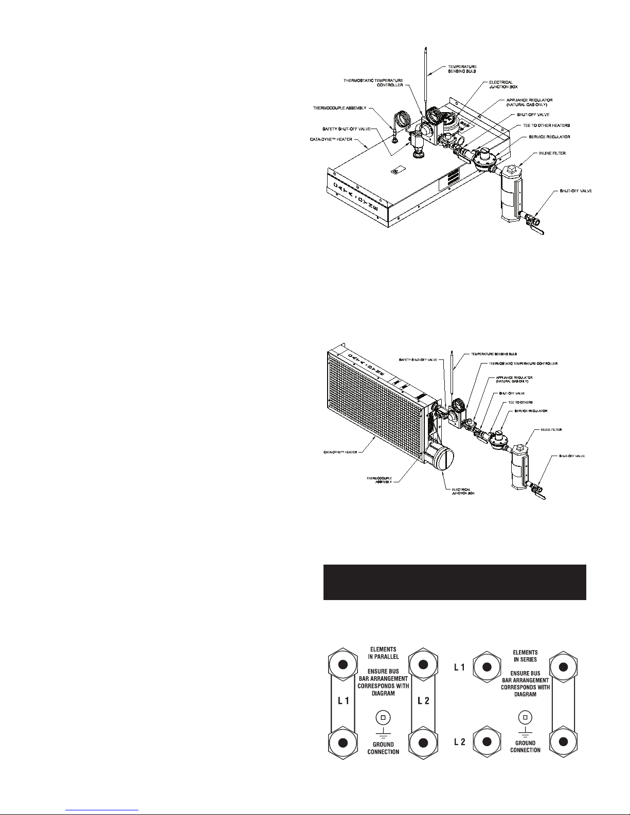
FIGURE 2
Diagram illustrates typical Natural Gas installation.
Gas appliance regulators and manual shut off valves are
required standard components for all CSA approved heaters;
they are available as optional accessories for FM approved
heaters.
All components should be installed as indicated in
6.
Figure 2 (WX and BX models only) or Figure 3 (MKII
model only).
Electrical
1.
All wiring is to be installed in accordance with the latest
revisions of the Canadian Electrical Code (CEC)/
National Electrical Code (NEC) and/or any applicable
local codes.
2.
It is desirable to install an indicating light on all starting
systems. This will reduce the possibility of the power
being left on once the heater is started, which can
severely reduce the lifespan of the heater.
3.
Ground connections for 120 V and higher voltage
heaters are required as indicated in Figures 4 and 5.
The number of terminals in the junction box can be two
.
4
of four depending on the number of elements used in
the fabrication of the heater. All MKII models incorporate
a single element and therefore have only two terminals.
The connection procedure for the different combinations
is as described in Figures 4 and 5:
FIGURE 3
Diagram illustrates typical Natural Gas installation.
Gas appliance regulators and manual shut off valves are required
standard components for all CSA approved heaters; they are
available as optional accessories for FM approved heaters.
CAUTION:
Install MKII series heaters with controls on sides or bottom of heater
only.
FIGURE 4
FIGURE 5
Page 4

Ventilation
The catalytic reaction in Cata-Dyne™ heaters occurs
when natural gas or propane reacts with oxygen to
produce water vapor, carbon dioxide and infrared energy.
Ventilation must be provided to allow adequate supply of
oxygen for the reaction.
For every 1.0 ft2 (0.093 m2) of heater surface, 50 ft3/hr
(1.42 m3/hr) of air supply is required. For example, a WX
24 x 24 heater (20,000 Btu/hr / 5.857 kW) would require
200 ft3/hr (5.66m3/hr) of air to ensure proper operation of
the Cata-Dyne™ heater.
To reduce the carbon dioxide and water vapor
concentrations in the building, a vent hood assembly can
be installed to provide positive ventilation from the heater
(See Figure 6).
FIGURE 6
4. Turn on the power to the electrical elements.
5. After 15 minutes, depress the reset button on the top
of the 100% safety shut-off valve. The button should
return to the original position and internally open the
valve and allow gas to flow to the heater. If the valve
does not stay open when the reset button is released,
it may be necessary to wait an additional few minutes
and then depress the reset button again. This will allow
the electrical elements additional time to warm up.
6. When the catalytic reaction is well established, turn off
the electrical power to the elements.
7 If the heater is equipped with a thermostatic
temperature controller, it can be set to the desired
setting after the catalytic reaction has been established
for at least one hour.
Shut Down
Turn off the gas supply to the heater.
OPERATION
All Cata-Dyne™ heaters are supplied with a Safety Shut-Off
Valve (SSOV)/Thermocouple assembly to ensure the safe
operation of the heater. Under no circumstances should the
reset button be held or locked into the depressed position
by use of a mechanical restraint. A tamper resistant model
SSOV is available if desired.
Start-up
1. Ensure the heater has been installed according to all
instructions and relevant codes.
Multi-Heater Start-up
Cata-Dyne™ heaters can also be purchased/installed in multiheater assemblies. If these assemblies are 12 V, each heater
must be started individually. This ensures the correct voltage
and current will be reaching the heater from the power supply.
12 V HAZARDOUS
ELECTRICAL INSTALLATIONS
Most oil and gas production buildings have an area
classication as follows:
1. Class I, Division 1, within the building.
Refer to gures 7 and 8.
2. Class I, Division 2, up to 10 ft. (3 m.) from the building
in any direction. Refer to gures 7 and 8.
3. Class I, Division 2, between 10 ft. (3 m.) and
25 ft. (7.6 m.) from the building in all directions at an
elevation of 18 in. (0.45 m.) above the ground.
Refer to gures 7 and 8.
Connection to the power supply must be outside of the
Class I, Division 2 location. (refer to Figure 9). All electrical
apparatus and wiring within this area must conform to the
appropriate codes.
2. Turn on the main gas supply to the system.
3. If the heater is equipped with a thermostatic
temperature controller, rotate the dial completely
clockwise to the fully open position.
Page 5

SPACE HEATING
A separate heat load calculation should be done for each
building in which a Cata-Dyne™ heater will be installed for
space heating purposes.
The heatload calculation determines the building heat losses
through the structure and allows for air infiltration (refer to
the Cata-Dyne™ catalog or visit www.ccithermal.com for the
sample Heat Load Calculation).
Cata-Dyne™ heaters produce low intensity infrared heat that
is absorbed by objects within the range of the heat source.
The closer the object is to the source of heat the more
heat the object will absorb. Cata-Dyne™ heaters should
be placed close to the floor level within the building to heat
objects close to the floor.
Ideally, Cata-Dyne™ heaters should be mounted 1-3 ft.
(0.3-1 m) from the floor and equally spaced around the
building perimeter for space heating applications.
If low mounting is not practical, then overhead mounting may
be utilized. Overhead mounted heaters should be sloped
face down to a maximum 45° angle to direct the infrared
energy towards the floor. Overhead mounting should be
restricted to heaters of 30,000 Btu.hr (8.8 kW) capacity and
larger.
If the building requires only one heater, place the
Cata-Dyne™ heater as close as possible to the center of the
longest wall.
For multiple heater installations, space the Cata-Dyne™
heaters as evenly as possible around the perimeter of the
building.
FIGURE 7
15 ft.
10 ft.
4.6 m
Vehicle located outside
hazardous area
FIGURE 8
Class I
Division 1 (Zone 1)
Class I
Division 2 (Zone 2)
3.0 m
10 ft.
3.0 m
Class I Division 2 (Zone 2)
18 in. (0.46 m) above ground
Subject to possible
transient vapour
18 in.
0.46 m
15 ft
4.6 m
SPOT HEATING
There are several factors to consider when Cata-Dyne™
heaters are utilized for spot heating.
Infrared energy travels in straight lines from the face of the
Cata-Dyne™ heater covering approximately 160° of an arc
and is inversely proportional to the square of the distance.
The heater should therefore be mounted as close as
practical (min of 28 in. (71 cm)) to the object requiring heat
for maximum temperature rise.
Make sure the piping is large enough to handle the gas load
(refer to the sample Piping Calculation in the Cata-Dyne™
catalog for sizing information).
Make sure the electrical starting system has sufficient
current carrying capacity and conforms to all applicable
electrical codes.
It is advisable to install an indicator light in the electrical
circuit to reduce the possibility of the power being left on
once the heater is started.
FIGURE 9
Standard
CAUTION:
Connect battery
outside 25 ft. (7.6 m)
in non-hazardous area
OUTSIDE BUILDING - Class I Division 2
area use appropriate electrical fittings
25 ft.
7.6 m
battery cable
Match the shape of the object requiring heat with the
appropriate Cata-Dyne™ heater, e.g. WX/BX 6 x 24 for long
narrow objects or WX/BX 12 x 12 for a square object.
Objects requiring heat should be painted dull, dark colors for
maximum infrared absorption and objects not requiring heat
should be painted light or reflective colors.
Insulate and protect plastic, rubber and similar materials from
direct intense infrared heat.
Building wall
CATA-DYNE Heater
c/w explosion proof
junction box
_
+
INSIDE BUILDING -
Seal
Class I Division 1 area use
appropriate electrical fittings
Page 6

PERSONAL SAFETY
GUARANTEE
The Cata-Dyne™ flameless infrared catalytic gas heater
does not produce harmful carbon monoxide gas when used
with natural gas or propane. Adequate ventilation must
be incorporated in any building design to ensure oxygen
replenishment and removal of any carbon dioxide. Protective
grills should be used on any installation where personnel may
come in contact with the face of the heater.
ORDERING INFORMATION
You can order any of CCI Thermal’s products by telephone,
fax, mail, e-mail or directly on-line at www.ccithermal.com.
To assist us in processing your order as quickly and efciently
as possible, please provide us with the following information:
□ Cata-Dyne™ product name
□ Cata-Dyne™ model number
□ Fuel gas - natural gas or propane
□ Starting voltage - 12, 24, 120, 208, 240, 480, or 600V
□ Accessories required:
- Protection Grill
- Wall Mount Brackets
- Thermostat
- Regulator
- Start Up Leads (12 V system only)
- Vent Hood
- Other
Under normal use the Company warrants to the purchaser
that defects in material or workmanship will be repaired
or replaced without charge for a period of 18 months from
date of shipment, or 12 months from the start date of
operation, whichever expires rst. Any claim for warranty
must be reported to the sales ofce where the product was
purchased for authorized repair or replacement within the
terms of this warranty.
Warranty is void if Cata-Dyne™ heaters are used with sour,
dirty or wet gas, or where sulphur content is greater than
allowable for utility gas specifications. Warranty is void if,
upon our inspection, if the SSOV or thermocouple have been
tampered with. Neither CCI Thermal nor the selling dealer
shall be held responsible for loss of time, inconvenience,
commercial loss or consequential damages relating to the
use of Cata-Dyne™ heaters.
REPAIRS
Cata-Dyne™ heaters may require periodic maintenance
or repair. Our factory is staffed with technicians who are
qualied to perform any required repairs. The procedure
to follow to have a heater repaired is as follows.
Send the heater to our factory in Edmonton. Include the
following information with the heater:
□ Company name and address
□ Contact name
□ Company name and contact
□ Billing address and phone number
□ Shipping instructions
□ Special tagging instructions
□ Date required
□ Method of payment:
- on account - P.O. number required
- credit card - VISA or Mastercard number
- cash or cheque
RETURN GOODS POLICY
Prior written approval must be obtained from CCI Thermal
for the return of any Cata-Dyne™ product(s). A restocking
charge of 15% will apply. All returns must be shipped to
our factory in Edmonton, freight prepaid. Final acceptance
will be contingent on inspection at our factory.
□ Telephone number/fax number/e-mail
□ P.O. Number
□ Advise if an estimate is required prior to starting the
repair
□ Details on the repair or conversion required
□ Return shipping instructions
NOTE: Under the terms of our certication, all repairs
must be performed at our factory in Edmonton.
CLEANING
The Cata-Dyne™ heater box may be cleaned but only
once it has been allowed to cool. If your Cata-DyneTM
catalytic pad (white pad) is dirty it should never be
contacted in order to avoid damaging it. This means that
it should not be wiped down, sprayed with water or blown
with compressed air. Any contact with the catalytic pad
may damage the surface requiring the owner to return the
unit to the factory for repair.
Page 7

TROUBLE SHOOTING
1.
Ensure that the fuel matches that listed on the nameplate.
2.
Ensure that the voltage matches that listed on the nameplate.
3.
Check for any physical damage. All signs of physical
damage to the catalyst pad such as holes, tears or a general
deterioration of the catalyst bed signal that it is time to have
the heater repaired. Excessive vibration may cause damage
to the inner catalysts structure which may cause premature
failure.
4.
Check the gas supply pressure at the heater – 7 in. w.c. (1.73
kPa), 4.5 in. w.c. (1.12 kPa), or 3.5 in. w.c. (0.86 kPa) for
natural gas and 11 in. w.c. (2.72 kPa) for propane.
5.
Check the gas orice for obstructions or dirt and ensure
the size matches that listed on the nameplate. It may be
necessary to install a lter upstream of the heater or regulator
if the gas supply is dirty. If the fuel supply is constantly dirty
and/or wet it would be advisable to use bottled propane fuel.
6.
Check the mounting position of the heater. The face of the
heater should be preferably in the vertical position and should
not vary more than 45° from the vertical position for maximum
efciency.
7.
Check for saturation of the catalyst face caused by
condensation or rain running down the face of the heater. If
the heater has been exposed to water, it is advisable to place
the unit in a warm area for a period of a few hours or longer
if required. Once the moisture is removed, the heater can be
re-installed and re-started.
8.
Check the jumper cable size to ensure that the resistance of
the cable is not reducing the current to the heater. This would
not allow sufcient power to the electrical element to preheat
the catalyst to the activity temperature. It is recommended to
run the service vehicle at fast idle while starting the heater.
9.
Cata-Dyne™ heaters are designed to use clean fuel and
to be used in non-contaminated atmospheres. Sulphur
compounds in the fuel or atmosphere will poison the catalyst
bed over a period of time and render the heater inoperative.
If the heater has been exposed to sulphur compounds, it
should be sent to the factory for service.
10.
Avoid spraying the face of the heater with high-pressure air,
steam or water because this can damage the catalyst bed, if
physical damage is visible, return the heater to the factory for
servicing.
11.
Ensure that the temperature controller is correct for the model
size, fuel, and pressure specications for the heater it is tted
to. If the temperature controller is too low, the heater
have sufcient fuel rating to operate and will stop.
Separate Installation and Operation Instructions are available for oven and industrial heating applications.
will not
Printed In Canada
Page 8

5918 Roper Road, Edmonton, Alberta, Canada T6B 3E1
Phone: (780) 466-3178 Fax: (780) 468-5904
www.ccithermal.com
PLEASE ADHERE TO INSTRUCTIONS PUBLISHED IN THIS MANUAL.
Failure to do so may be dangerous and may void certain provisions of your warranty.
For further assistance, please call:
24 Hr. Hotline: 1-800-661-8529
(U.S.A. and Canada)
Please have model and serial numbers available before calling.
WARRANTY: Under normal use the Company
warrants to the purchaser that defects in material or
workmanship will be repaired or replaced
without charge for a period of 18 months from
date of shipment, or 12 months from the start date of
operation, whichever expires rst. Any claim for
warranty must be reported to the sales ofce where the
product was purchased for authorized repair or
replacement within the terms of this warranty.
Subject to State or Provincial law to the contrary, the
Company will not be responsible for any expense for
installation, removal from service, transportation, or
damages of any type whatsoever, including damages
arising from lack of use, business interruptions, or
incidental or consequential damages.
The Company cannot anticipate or control the
conditions of product usage and therefore
accepts no responsibility for the safe application and
suitability of its products when used alone or in
combination with other products. Tests for the safe
application and suitability of the products are the sole
responsibility of the user.
This warranty will be void if, in the judgment of the
Company, the damage, failure or defect is the result of:
• vibration, radiation, erosion, corrosion, process
contamination, abnormal process conditions,
temperature and pressures, unusual surges or
pulsation, fouling, ordinary wear and tear, lack of
maintenance, incorrectly applied utilities such as
voltage, air, gas, water, and others or any
combination of the aforementioned causes not
specically allowed for in the design conditions or
• any act or omission by the Purchaser, its agents,
servants or independent contractors which for
greater certainty, but not so as to limit the generality
of the foregoing, includes physical, chemical or
mechanical abuse, accident, improper
installation of the product, improper storage and
handling of the product, improper application or the
misalignment of parts.
No warranty applies to paint nishes except for
manufacturing defects apparent within 30 days from
the date of installation.
The Company neither assumes nor
authorizes any person to assume for it any other
obligation or liability in connection with the product(s).
The Purchaser agrees that all warranty work required
after the initial commissioning of the product will be
provided only if the Company has been paid by the
Purchaser in full accordance with the terms and
conditions of the contract.
The Purchaser agrees that the Company makes
no warranty or guarantee, express, implied or
statutory, (INCLUDING ANY WARRANTY OF
MERCHANTABILITY OR WARRANTY OF FITNESS
FOR A PARTICULAR PURPOSE) written or oral, of
the Article or incidental labour, except as is expressed
or contained in the agreement herein.
LIABILITY: Technical data contained in the catalog or
on the website is subject to change without notice. The
Company reserves the right to make dimensional and
other design changes as required. The Purchaser
acknowledges the Company shall not be obligated
to modify those articles manufactured before the
formulation of the changes in design or improvements
of the products by the Company.
The Company shall not be liable to compensate or
indemnify the Purchaser, end user or any other party
against any actions, claims, liabilities, injury, loss, loss of
use, loss of business, damages, indirect or consequential
damages, demands, penalties, nes, expenses
(including legal expenses), losts, obligations and
causes of action of any kind arising wholly or partly from
negligence or omission of the user or the misuse, incorrect
application, unsafe application, incorrect storage and
handling, incorrect installation, lack of maintenance,
improper maintenance or improper operation of
products furnished by the Company.
 Loading...