

Page 1

USER MANUAL
Table of Contents
1.0 Introduction..........................................................................1
2.0 Specifications.......................................................................2
3.0 Package Contents................................................................2
4.0 Panel Descriptions...............................................................3
5.0 Connection and Operation..................................................3
Page 2

HDMI SWITCH SPLITTER 4×2 (matrix)by Cat5
1
HDMI SWITCH SPLITTER
Dear customer
Thank you for purchasing this product. For optimum performance and safety,
please read these instructions carefully before connecting, operating or adjusting
this product. Please keep this manual for future reference.
1.0 INTRODUCTION
This 4X2 Matrix HDMI SWITCH SPLITTER by cat5e/6 offers unprecedented
flexibility and convenience by routing high definition audio/video from any of four
HDMI video sources to any of 2 displays over HDMI cable or 2 remote displays
over inexpensive, standard CAT5e/6 cable. It eliminates the need to disconnect
and reconnect sources to a display equipped with one input.
Two receivers work with the Switch Splitter as a full functional module. Full
High-Resolution HDTV signals are supported up to a resolution of 1080p over
HDMI cable 15m or at a maximum distance of .40M over two pieces of CAT5e/6
cable. The 4X2 Matrix HDMI SWITCH SPLITTER works with HD-DVD players,
TiVo systems, HT PCs, and satellite set-top boxes that connect to an HDMI
display. Every source and display is accessible at all times by selecting it with an
IR remote, ,front panel buttons or through RS232 port.
1.1 FEATURES
This product has many features that enable it to perform in a superior manner.
Among those features you will find:
l Allows any HDMI display to view any source at any time
l Allows any source to be displayed on multiple displays at the same time
l HDMI or DVI to HDMI cables are used to connect the inputs and the matrix
output
l Each Output includes one HDMI output and UTP output over cat5e/6, but only
one way is available at a time.
l Each UTP output is connected to a Receiver.
l UTP output extends signal up to 40m for 1080p by UTP cable with cross stand
inside.
l Each Input includes an infrared Emitter, which is used to control the
long-distance source device by Remote Control.
l Each display's inputs can be switched with the IR remote control, front panel
buttons or through RS232
l Supports highest video resolution 1080p.
l Supports 225MHz/2.25Gbps per channel (6.75Gbps all channel) bandwidth.
l Supports 12bit per channel (36bit all channel) deep color.
l Supports HDCP
l Supports uncompressed audio such as LPCM.
l Supports compressed audio such as DTS Digital, Dolby Digital(including
DTS-HD and Dolby True HD).
Page 3

HDMI SWITCH SPLITTER 4×2 (matrix)by Cat5
2
2.0 SPECIFICATIONS
Signal Inputs/Output
HDMI Connector type A 19 pin female
Input DDC Signal 5 volts p-p (TTL)
Control Port RS-232 Female, Mini-Stereo
Output Signal HDMI output, UTP output
Operating Frequency
Vertical Frequency Range 50/60Hz
Video Amplifier Bandwidth 2.25Gbps/225MHz
Resolutions(HDTV)
Interlaced(50&60Hz) 480i,576i,1080i
Progressive(50&60Hz) 480p,576p,720p,1080p
Mechanical
Size of HDMI Switch Splitter (L-W-H) 270x183x41MM
Weight of HDMI Switch Splitter (Net) 1365g
Warranty
Limited Warranty 1 Year Parts and Labor
Environmental
Operating Temperature
0 ℃ to +70℃
Operating Humidity 10% to 85 % RH (no condensation)
Storage Temperature
-10℃ to +80℃
Storage Humidity 5% to 90 % RH (no condensation)
Power Requirement
Power Supply for HDMI switch splitter 5V DC@2A; 8W
Power Supply for Receiver 5V DC@2A; 5W
Regulatory Approvals
Converter Unit FCC,CE,UL
Power Supply UL,CE,FCC
Accessories Adapter
AC Power Adapter US standard, UK standard and so on
User Manual English version
Note: Specifications are subject to change without notice.
3.0 Package Contents
Before attempting to use this unit, please check the packaging and make sure the
following items are contained in the shipping carton:
Packaging of Main Unit
1) HDMI 4X2 Switch Splitter
Page 4
HDMI SWITCH SPLITTER 4×2 (matrix)by Cat5
3
2) Remote Control
3) Infrared Extender. (IR)
4) 5V@2A DC Power Supply
5) User’s Manual.
Packaging of Accessories
6) Two Receivers
7) Two pieces of Remote Control for Receivers
8) Two pieces of External infrared emitter (IE)
9) Two pieces of 5V DC @2A Power Supply.
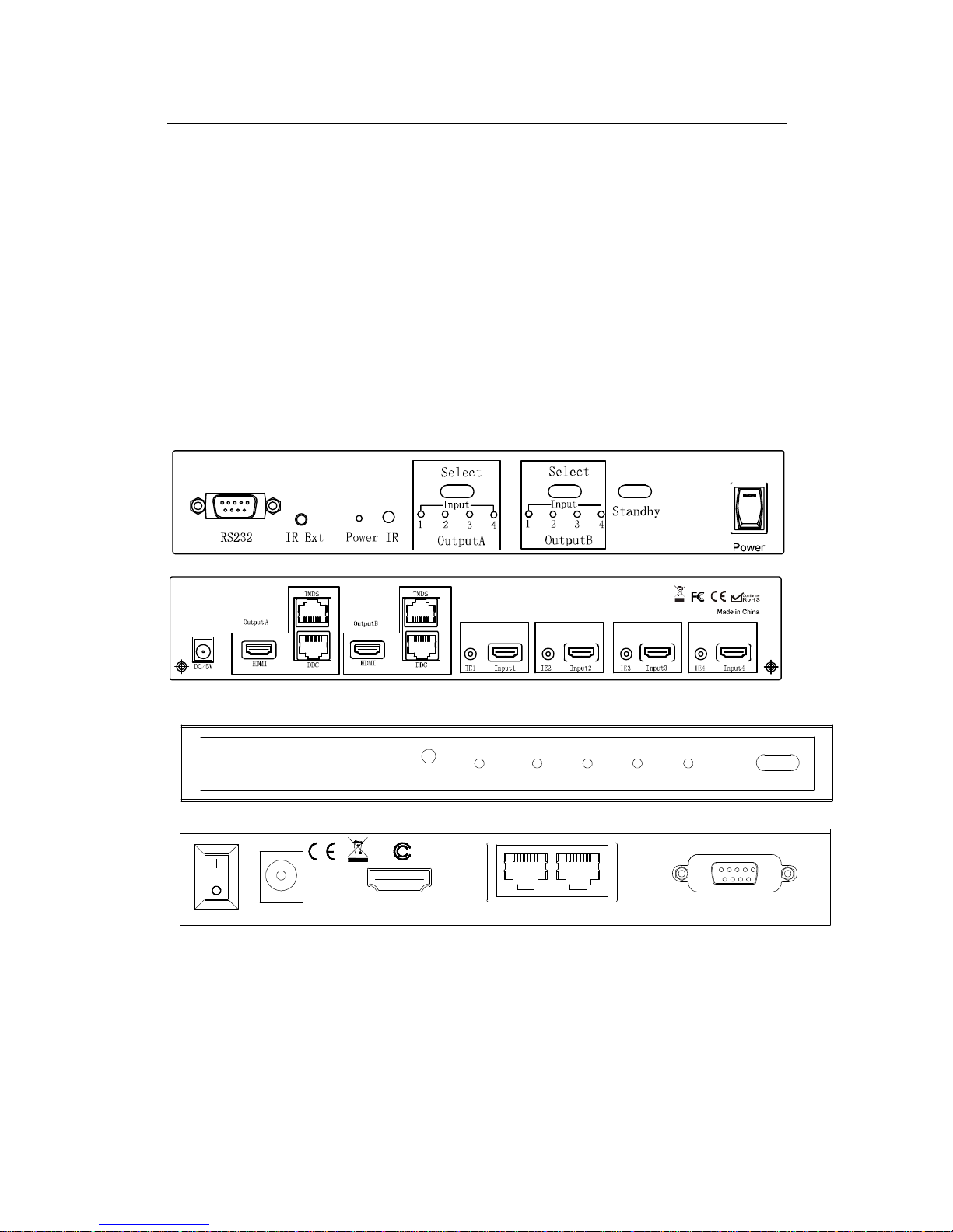
4.0 PANEL DESCRIPTIONS
Please study the panel drawings below and become familiar with the structure.
HDMI 4X2 Matrix By CAT-5e/6
Receiver
F
RS232
DDCInput
TMDS
DC/5V
Output
321
IR
Power
4
Select
5.0 Connection and Operation
5.1 Connection
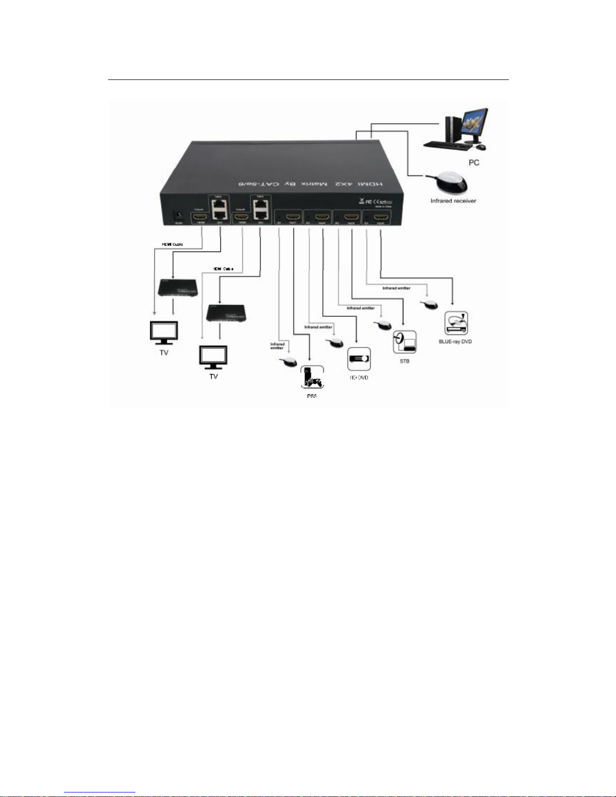
1) Connect all source devices to the HDMI inputs on the Switch Splitter.
2) Either HDMI or UTP can be selected as signal output for Output A/B. When
choosing the HDMI as signal output, connect displays and main unit directly
Page 5

HDMI SWITCH SPLITTER 4×2 (matrix)by Cat5
4
over HDMI cable. When choosing UTP as signal output, connect receivers and
main unit over cat5e/6 cable, and then connect output of receivers to displays.
(Note: HDMI and UTP of each output can not be connected simultaneously)
3) Connect the 5V@2A power supply to the Switch Splitter, and 5V@2A power
supply to each receiver.
Note: 1) Please make sure to cut off the power before insert IR Extender into the
Converter.
2) Please make sure to insert the plug of IR Extender into the Converter
completely.
Attention: Insert / Extract cable gently.
5.2 Operation
1) When supplied with power, the output A and output B will select Input 1 at the
same.
2) Selecting source devices by buttons
Two buttons on the Switch Splitter are used to select source devices circularly
for outputs A and B. Once you press the button, it will select next available source
device.
3) Selecting source devices by IR remote
1. Power button
The power button of the IR remote can control the power of the Switch
Splitter. Pressing this button, the power-on unit will be turned off. If you
press it again, the unit will be turned on.
2. Other buttons
Depending on outputs A, B, the other buttons of the IR remote can be
divided into four groups. Each group has five buttons: ‘off’— turn off its
outputs. 1, 2, 3, 4 are used to select input port accordingly.
4) Selecting source devices by RS232
①. Introduction of RS232 remote operation:
RS232 remote operation is mainly based on the “super terminal” of
Windows operation system. Its parameter should be: ANSI 4800 8-N-1-non
②. Operation
A. Connect the switch splitter to the COM of PC with a RS232 cable.
B. Chose the right COM when you setting “super terminal” and then set the
parameter as follow:
Baud frequency:4800
Data bit: 8
Parity bit: N
Stop bit: 1
Data stream: NON
C. Inputting your instruction. The instruction should be two or three letter, and
finish with “Enter” button.
Page 6

HDMI SWITCH SPLITTER 4×2 (matrix)by Cat5
5
Please input next instruction in three seconds or the”Overtime instruction”
will appear.
The input instruction should be right, or you will be rejected with the “wrong
instruction”
If the input or output that you chose is not connected to devices or not in
power-on mode, “ineffective instruction” will inform you.
If your instruction is performed, you can see the instruction of “successful
operation”.
③. Instruction input method
A. Selecting source device
Sequence number of output (A/B) + sequence number of the input
(1/2/3/4) + “Enter”
For example: If you want display B to view source 3, then you can input “B3
“and finish with “Enter”.
B. Turning off an output
C + Sequence number of the output that you want to turn off (A/B) +
“Enter”
For example: If you want to turn off output B, then you can input CB, and
finish with “Enter”.
C. Turning off the Switch Splitter:
OFF + “Enter”
D. Turning on the Switch Splitter:
ON + “Enter”
E. Inquiry:
QS + “Enter”
This order enables you know which input and output are available and the
connections of input and output.
5.3 CONECTION DIAGRAM
Page 7
HDMI SWITCH SPLITTER 4×2 (matrix)by Cat5
6
P/N3011
 Loading...