

Page 1
®
FLEXIBLE AND
EFFICIENT DEMOLITION
330D, 345C, 365C, 385C ULTRA-HIGH DEMOLITION (UHD)
Page 2
A Dynamic and Complex Business
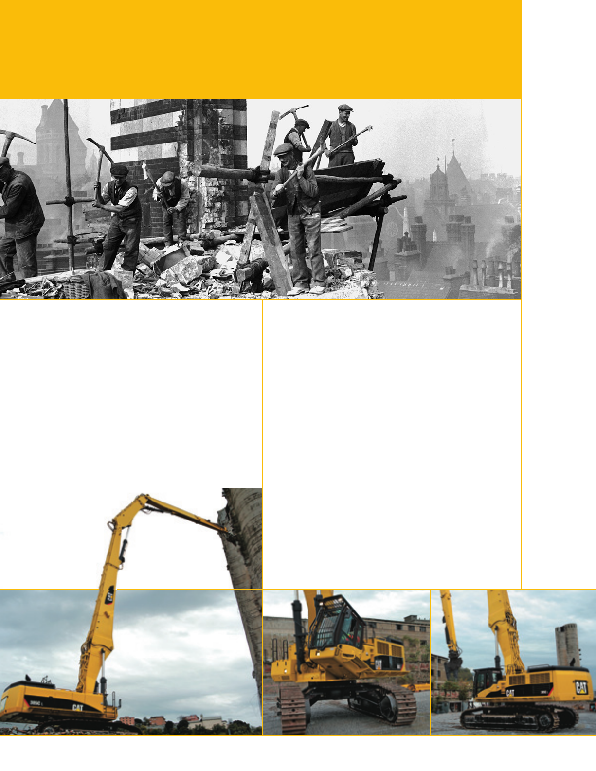
Demolition has changed. It has become a dynamic
and increasingly complex business. Today there are
few demolition jobs where buildings can simply be
knocked, pulled or blown down using traditional
tools. What’s more, contract periods ar
shorter, legislation is stricter, environmental
pressure is increasing and skilled labor is harder to
find. As a consequence, demolition contractors ar
looking for the most efficient, cost effective and
safe methods of deconstructing buildings and
structures.
e becoming
e
2
Page 3
Increasing Productivity throughout
the Process
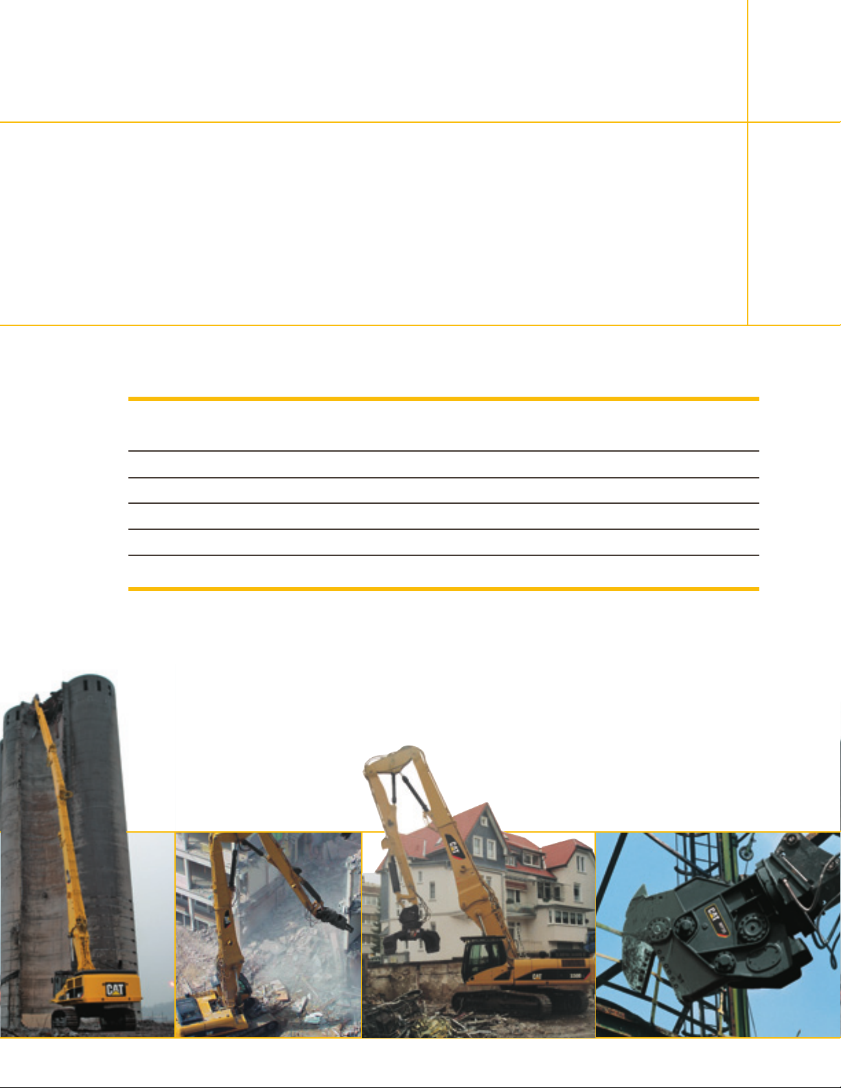
Caterpillar engineers have designed and produced specialized machines with the objective of
increasing productivity at every stage of the process. Added to that, our machines have been
developed with an emphasis on stability, durability and ease of use. They also come with the backing
®
of your local Cat
advise you how to get the most out of your equipment.
Ultra High Demolition
dealer. They can help you with finding the right machine and tools for the job and
Weight*
metric tons/tons
330D UHD (21 m) 47.9/52.8 21 300/839 13 900/547 3000/6,614 2700/5,953
345C UHD (26 m) 66.7/73.5 26 100/1,028 16 400/646 3300/7,275 3000/6,614
345C UHD (28 m) 67.0/73.9 27 900/1,098 18 200/717 2500/5,512 2500/5,512
365C UHD (33 m) 85.7/94.5 33 100/1,303 21 500/847 3000/6,614 2000/4,409
385C UHD (40 m) 98.7/108.8 39 500/1,555 25 200/992 2400/5,291 2100/4,630
* Maximum weight in UHD configuration. Figures are approximate and do not include the tool.
** Includes potential quick coupler and mounting bracket.
Max pin
height
mm/in
Max horizontal
pin reach
mm/in
Max tool weight
(over the front)**
kg/lb
Max tool
weight (360°)**
kg/lb
3
Page 4
Visual Overview – Index
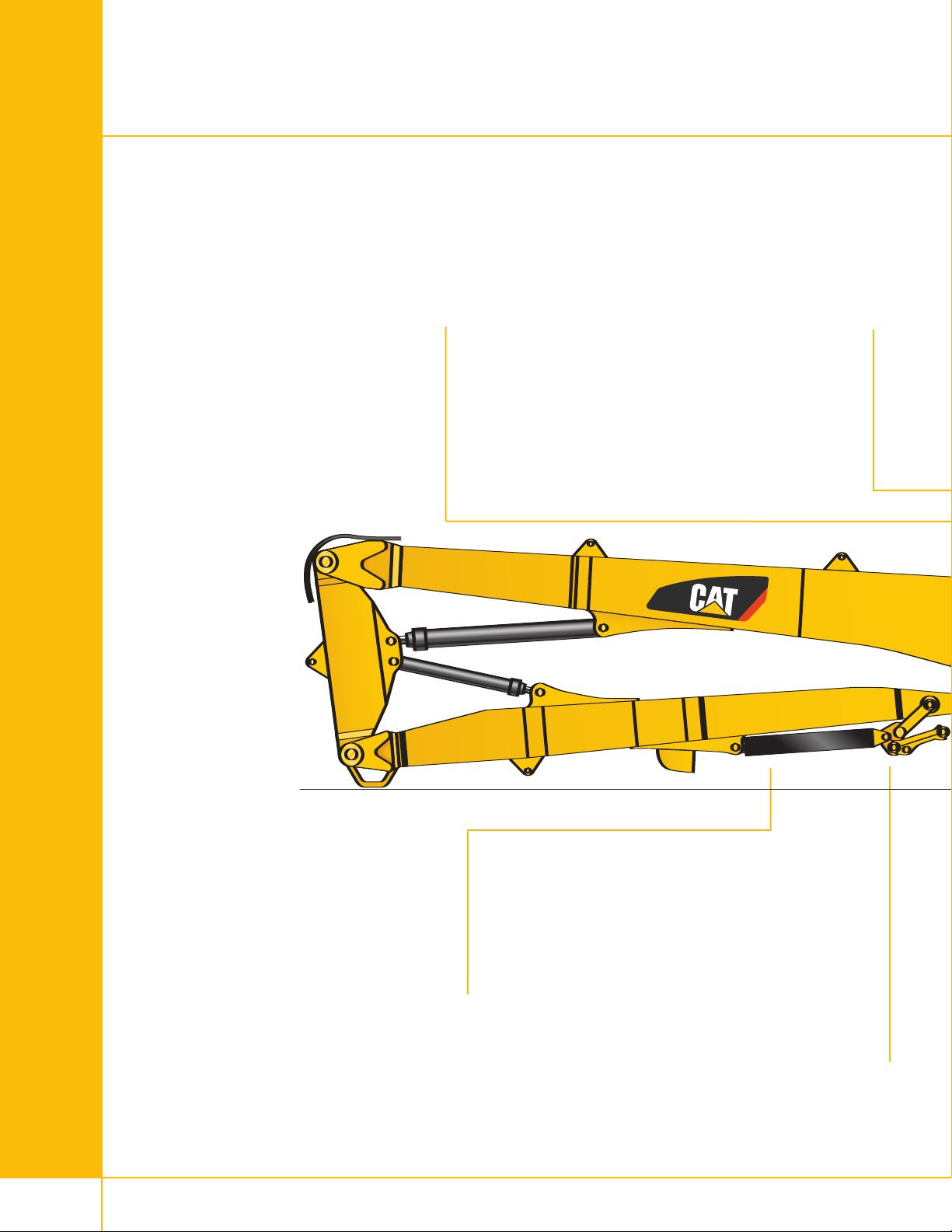
Hydraulic Quick Disconnects
and face-to-face ball valves p. 10
Hydraulic lines are fitted with quick
disconnects or face-to-face ball valves
to reduce the time needed to change
the front parts.
Boom Hook System p. 10
A reliable boom hook system enables
to switch from Ultra High Demolition
(UHD) front parts to demolition
configurations. These retrofit booms
can be installed either in bent or in
straight position.
Tool Cylinder protection p. 7
Thanks to this metal box, the tool cylinder
is protected in all working positions.
4
Ultra-High
Demolition Linkage p. 9
Optimized working range and impr
tool controllability, thanks to an
UHD-dedicated tool linkage.
oved
Page 5
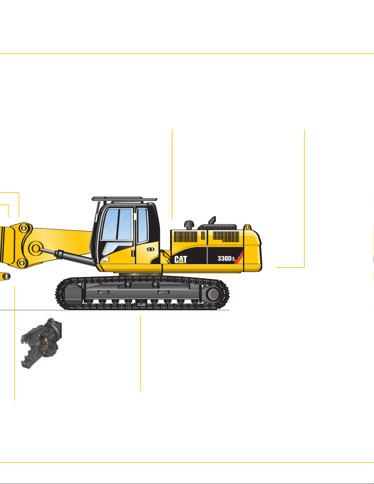
Integrated Tiltable
Demolition Cab p. 8
Hydraulic cab tilting device for operator
comfort. Enhanced upper visibility
through larger impact-resistant windows
with Falling Object Guard System (FOGS).
Heavy Duty Upper Frame p. 6
Reinforced structures to withstand the
extreme conditions of the demolition
applications.
Tools p. 17
Several tool options
maximize versatility.
Undercarriage p. 11
Hydraulic adjustable
under
riage is standar
car
d on
the 330D UHD and the 345C UHD.
385 fixed undercarriage is
standard on the 385C UHD and
the 365C UHD.
5
Page 6
Reliability
Several major features make the Caterpillar Ultra High Demolition (UHD) models the most reliable machines in
demolition applications.
Upper Frame and Counterweight
Purposely designed and built for extreme conditions.
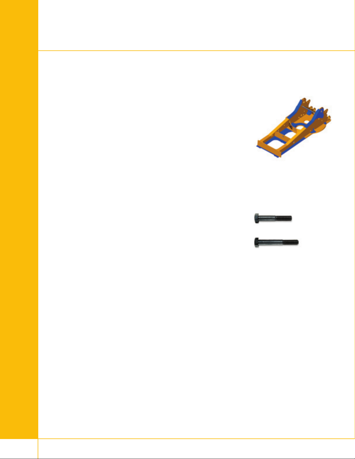
Reinforced upper frame
The heavy-duty reinforced upper frames of the CAT UHD models are
designed to withstand the extreme load conditions of demolition applications.
Compared to a standard upper frame, several additional plates provide the
durability and strength required in these environments.
ced upper frame
Reinfor
Swing bearing to upper frame bolts
The swing bearing bolts are 20 mm longer on the back half of upper frame
for increased joint retention. Bolt grade is increased from 10.9 to 11.9 for
increased bolt torque of swing bearing to upper frame and carbody.
Counterweight
A heavier counterweight balances the swing bearing and provides enhanced
stability.
Front Parts
fles which give the
All Caterpillar®booms and sticks have inter
uctures extra strength and durability. They are designed based on a
str
precise finite element analysis that highlights all the potential stress areas
under all possible load cases. These specific areas are then reinforced
accordingly.
Caterpillar excavator booms and sticks are built for performance and long
service life.
– Castings and forgings are used at high stress areas such as boom nose,
boom foot, boom cylinder and stick foot.
Large, welded, box-section str
–
in high-stress areas to better withstand torsional loads.
– All booms and sticks go through a stress relief heat treatment to maximize
fatigue life and durability
uctur
.
nal baf
es with thick, multi-plate fabrications
Standard
Heavy-duty
Swing bearing bolts
6
Page 7
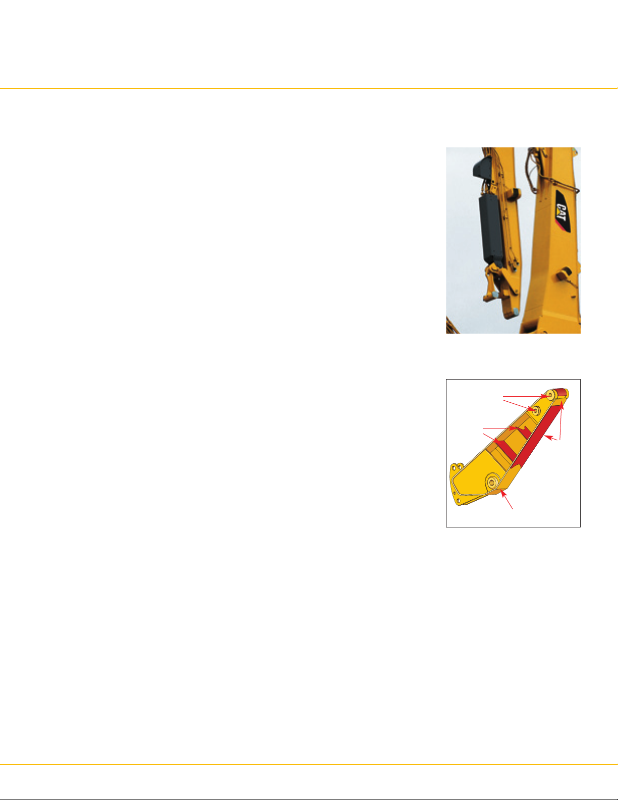
Tool Cylinder Protection
To prevent damage to the tool cylinder rod caused by falling concrete and
debris, the tool cylinder is equipped with a heavy duty metal cover. Thanks to
its unique construction, the cover protects the cylinder rod in every position.
Tool cylinder protection
Demolition Sticks
The Demolition sticks are made of thick plates (on top, bottom and side) and
have additional internal baffles to improve their resistance to torsion stresses.
They also feature hardened bores at all connections (connections with boom
and tool linkage). Additional wear plates on the bottom side and around the
nose extend the whole stick life.
H
ardened
Additional
internal
baffles
Demolition sticks
bores
Hardened
bore
Bottom
wear
plate
+ thicker plates
(top, bottom
and side)
7
Page 8
Operator Comfort and Safety
Operator comfort and safety is critical in demolition applications.
Hydraulically tiltable cab
The hydraulically tiltable cab tilts back to further improve upward visibility
and to allow the operator to adopt a more comfortable body position.
The tiltable cab is integrated into the upper frame and therefore does not
increase the machine's shipping height. Moreover, because of the integration
into the upper frame, no tilt parts are exposed to the demolition environment.
To reduce vibrations and sound, the cab shell is attached to the frame with
viscous mounts.
Automatic climate control
Fully automatic climate control adjusts temperature and flow and determines
which air outlet is best in each situation.
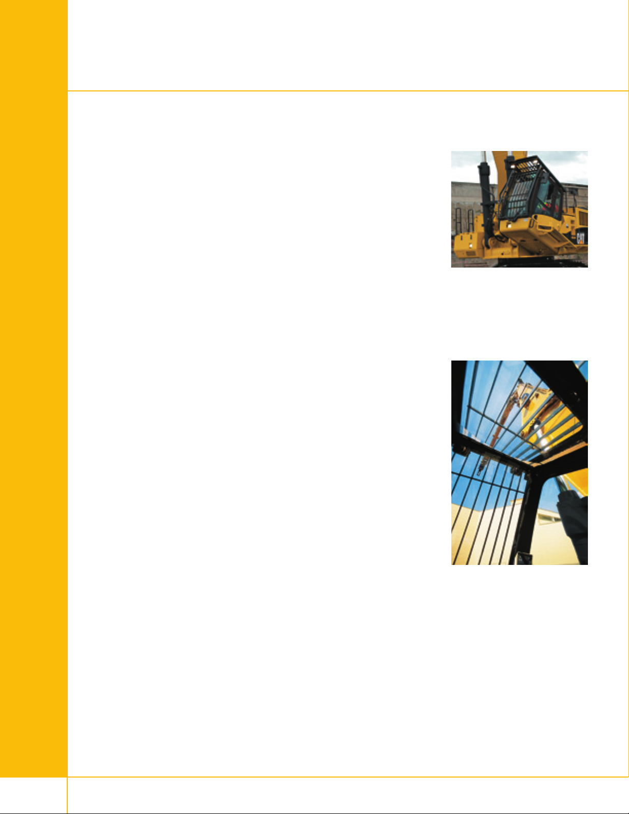
High visibility demolition cab
The thick laminated safety glass front window is one-piece with a bottom
mounted parallel wiper for excellent visibility. For enhanced upward visibility,
the impact resistant top window extends completely to the rear and has
a wiper and washer.
Falling object guard
The ISO 10262-1998 and SAE J1356 certified falling object guard on top and
front of the cab is standard. The crossbars of the top guard are angled in line
with the operator’s sight for enhanced visibility of the work tool. The front
guard swings out for easier windshield cleaning.
8
Page 9
0
1
2
3
4
5
6
7
8
9
10
11
12
13
1
4
1
5
16
17
18
19
2
0
2
1
22
m
1413121110987654321012
Productivity
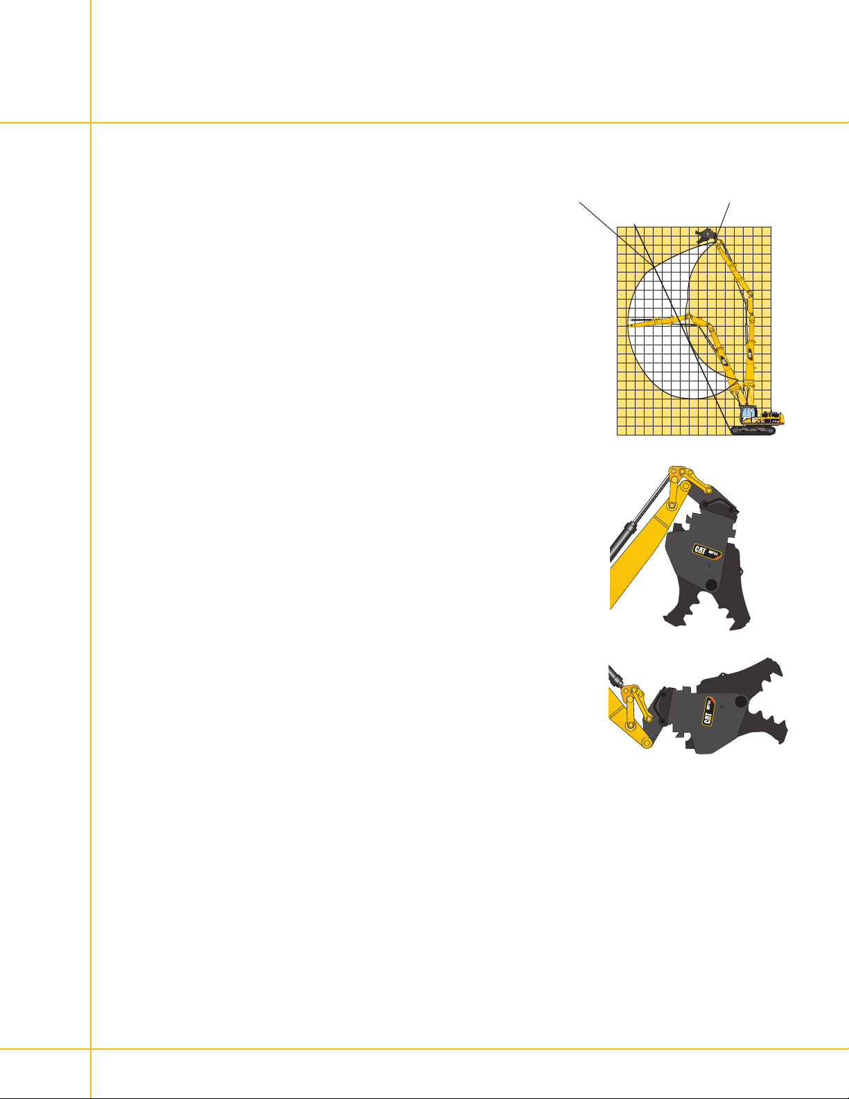
Cat Ultra High Demolition (UHD) machines are designed for maximum productivity in all demolition applications.
Maximum pin heightMaximum working height
Working Height
While the maximum pin height is given as a reference to compare machines,
the actual “working height” is always different. An experienced operator will
never work above a safety line that extends from the front edge of the tracks
and follows a “1:2” rule (2 meters of vertical height for 1 meter of horizontal
reach). Working under this line is generally accepted as a safety rule to avoid
any risk of debris falling on the machine. Caterpillar UHD excavators have
been purposely designed with the “1:2” line in mind and show therefore best
working heights and enhanced performances along that line.
Dedicated UHD tool linkage
Because UHD applications require different working positions than standard
applications, CAT engineers developed a purpose-designed linkage for the
UHD front parts. Besides providing an optimized working envelope, this
linkage also greatly improves the tool controllability.
1:2” line
“
9
Page 10
Versatility
The extreme versatility of the Cat Ultra High Demolition (UHD) models enable these machines to work in a wide range of
applications, like truck loading.
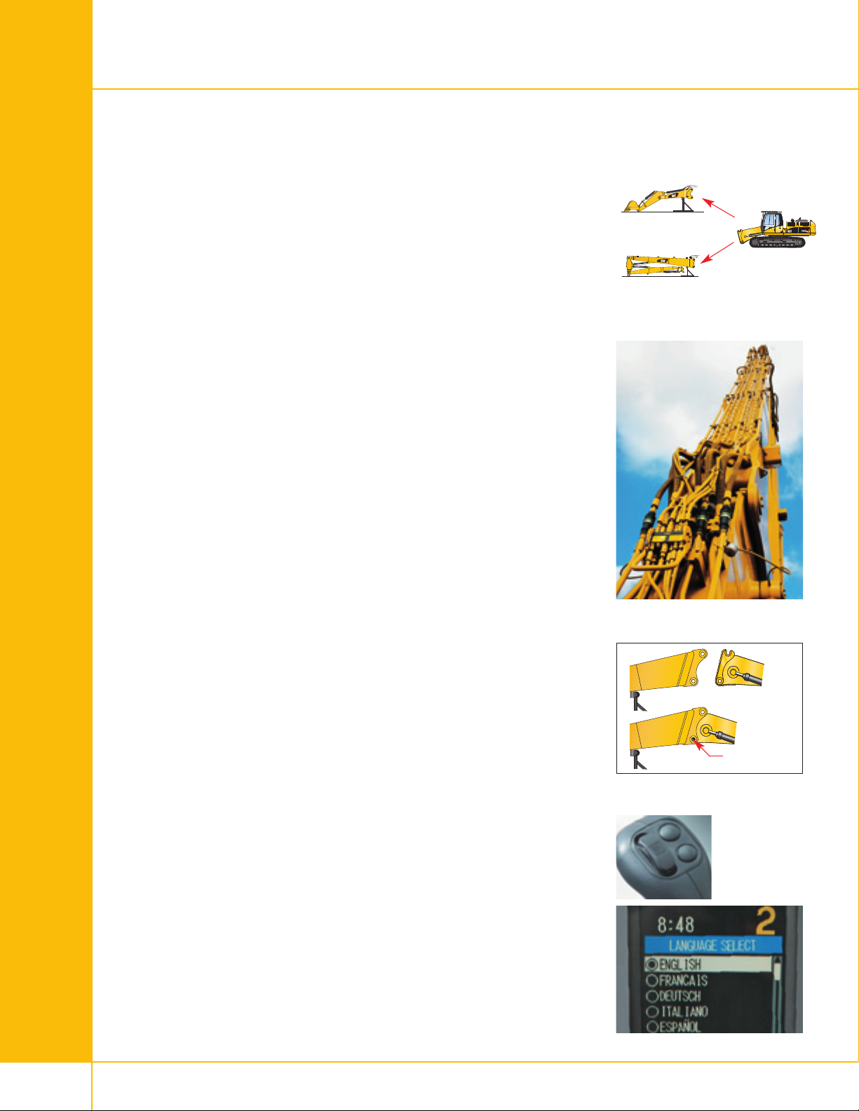
Retrofit (short 2P)
Versatility – retrofit
A short boom nose can be hooked onto the bottom foot. To maximize the
machine's extreme versatility, this boom nose can be put in two different
positions. The straight position is ideal for working in above ground level
applications, such as low level demolition or sorting. The bent position can
be used for applications such as digging or truck loading. Optional medium
pressure lines also enable the use of tilting buckets and tool rotation.
Boom Hook System with Quick Disconnects
Boom hook system
The front parts are equipped with a reliable and safe hook system between
the boom foot and boom nose. Compared to the traditional pin-mounted joint,
the hook system significantly reduces the time needed to change between
the Ultra-high front parts and the retrofit configurations. In principle, the
boom hook system consists of a hook to pick up the front parts and a
mechanical expander pin to secure them onto the boom foot. The absence of
any hydraulic parts, as well as a full length heavy duty one-piece securing
pin, ensure safe and reliable operation. The operator has an excellent view
of the hook system from the cab to easily change the front parts.
igh versatility
H
Hydraulic quick disconnects and face-to-face ball valves
On 330D, the hydraulic lines between boom foot and boom nose
are fitted with hydraulic quick disconnects to even further reduce the time
needed to change the front parts. Oil spillage and contamination is reduced
through the quick disconnects flat-face design. On larger models, face-toface ball valves assure the unmatched reliability required for high hydraulic
flows.
Tool Control System
ool control
T
Ten hydraulic pump flow and pressure settings can be preset on the monitor
onic Contr
(Electr
each time a tool is changed. Selecting the proper setting from the monitor's
menu instantly provides the operator with the correct amount of flow and
pressure for the tool. The unique Cat proportional sliding switches provide
modulation to the tool and make precision work easy.
ol System), eliminating the need to adjust the hydraulics
Hydraulic quick disconnects
slide-in expander pin
Boom hook system
10
ool contr
T
ol
Page 11
Undercarriage
Hydraulic adjustable undercarriage is standard on the 330D UHD and the 345C UHD. 385 fixed undercarriage is standard
on the 385C UHD and the 365C UHD.
Hydraulic Variable Gauge Undercarriage (HVG)
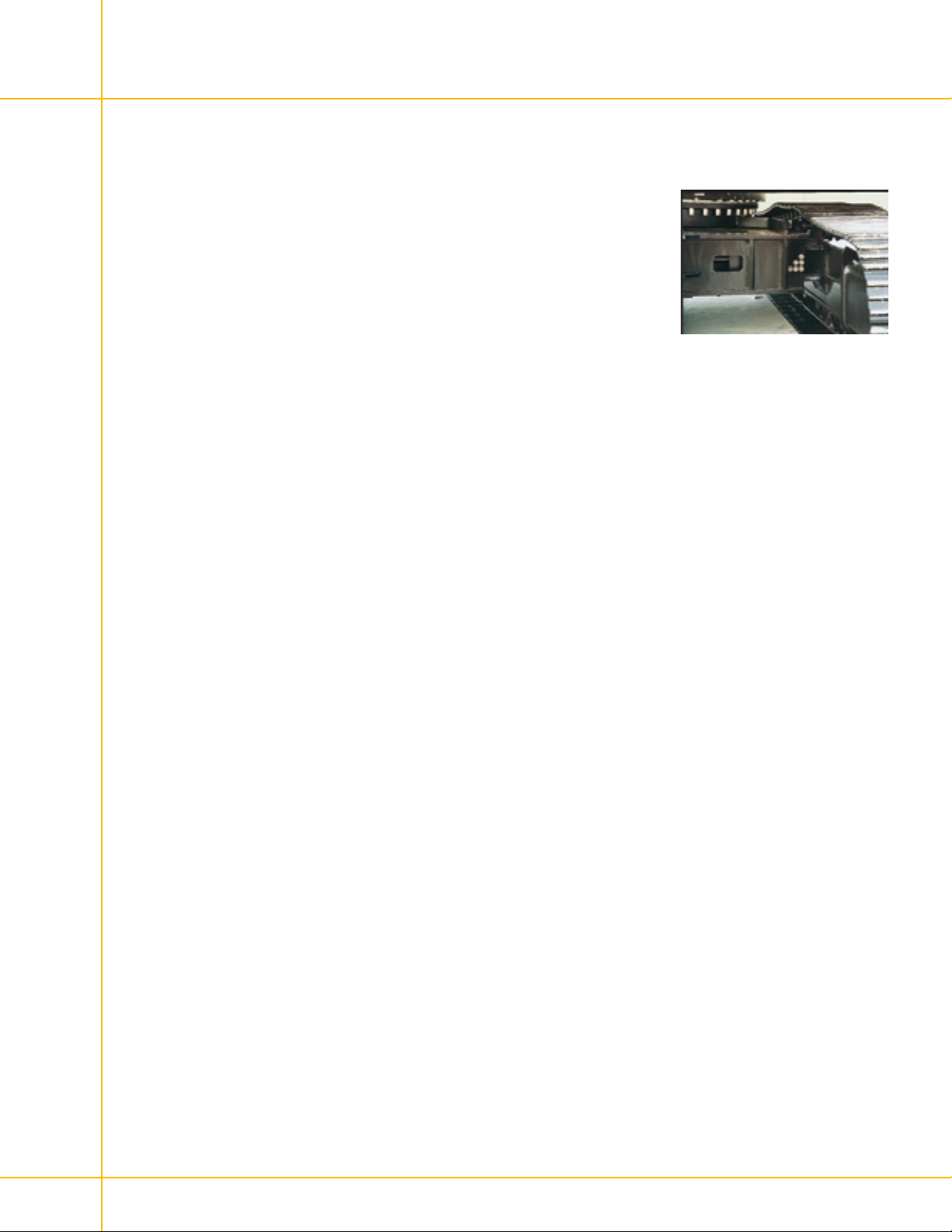
The hydraulic variable gauge undercarriage increases the stability through
increased track gauge in working position, as well as by lowering the center
of gravity of the machine. The non-bolt joint allows a change from shipping
to working width, or reverse, in less than one minute. Standard on the
330D UHD and the 345C UHD.
Fixed Undercarriage
The 365C UHD and the 385C UHD are standard with the 385C fixed
undercarriage.
330D HVG
11
Page 12
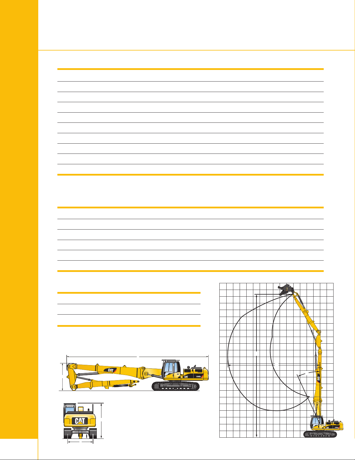
Specifications – 330D (21 m)
B
A
C
D
E
0
1
2
3
4
5
6
7
8
9
10
11
12
13
14
15
16
17
18
19
20
21
22
m
1413121110987654321012
B
C
A
Dimensions and Weights
Undercarriage
Shipping Length
A
Boom Height
B
Cab Height (with FOGS)
C
hipping Gauge (retracted position)
S
D
Working Gauge (extended position)
D
Ground Clearance
E
Machine Weight (UHD configuration) *
Machine Weight (Retrofit Configuration) **
Machine Weight (LRE Retrofit configuration)
* Without tool
** May vary depending on the stick and the bucket
Working Range
Undercarriage
A
Maximum allowable angle from vertical
B
Maximum Horizontal Reach
HVG
mm/in 14 830/584
mm/in 3100/122
mm/in 3410/134
m/in 2390/94
m
mm/in 2820/111
mm/in 480/19
kg/lb 47 870/105,535
kg/lb 47 350/104,389
kg/lb 46 960/103,529
HVG
25°
mm/in 13 850/545
C
Maximum Pin Height
Maximum Tool Weight (over the front)
Maximum Tool Weight (over the side)
Engine Specs
12
Engine Cat C9 with ACERT™ Technology
Ratings rpm
Net Power (ISO 9249) kW/hp 200/270
Dimensions and weights Working range
mm/in 21 120/832
kg/lb 3000/6,614
kg/lb 2700/5,953
1800
Page 13
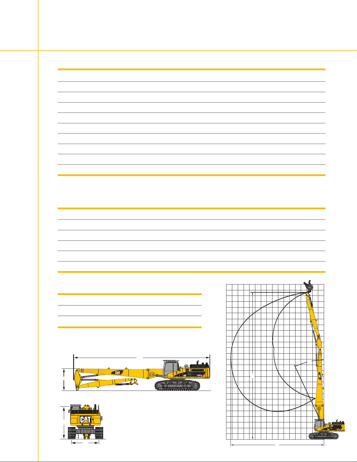
Specifications – 345C (26/28 m)
D
C
E
A
B
B
A
C
0
5
10
15
20
25
m
Dimensions and Weights
Undercarriage
A
Shipping Length
B
Boom Height
C
Cab Height (with FOGS)
D
Shipping Gauge (retracted position)
D
Working Gauge (extended position)
E
Ground Clearance
Machine Weight (UHD configuration) *
Machine Weight (Retrofit Configuration) **
Machine Weight (LRE Retrofit configuration)
* Without tool
** May vary depending on the stick and the bucket
Working Range
Undercarriage
Maximum allowable angle from vertical
A
Maximum Horizontal Reach
B
Maximum Pin Height
C
Maximum Tool Weight (over the front)
HVG
mm/in 17 800/701
m/in 3120/123
m
m/in 3720/147
m
mm/in 2400/95
mm/in 3010/119
mm/in 460/18
kg/lb 63 800-64 200/140,655-141,537
kg/lb 61 400/135,364
kg/lb –
HVG
25°
mm/in 16 400-18 150/646-715
mm/in 26 100-27 900/1,028-1,098
kg/lb 3300-2500/7,275-5,512
Maximum Tool Weight (over the side)
kg/lb 3000-2500/6,614-5,512
Example: 345C – 26 m version
Engine Specs
Engine Cat C13 with ACERT™ Technology
Ratings rpm
Net Power (ISO 9249) kW/hp 239/325
1800
Dimensions and weights
Working range
13
Page 14
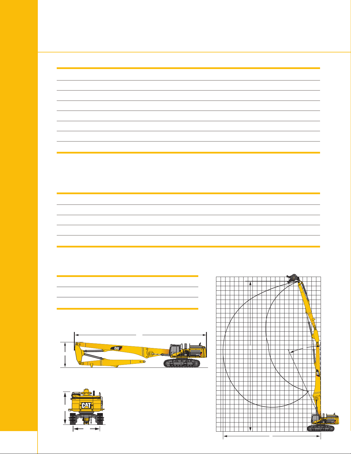
Specifications – 365C (33 m)
D
C
E
AC
B
5
10
15
20
25
30
m
A
B
Dimensions and Weights
A
Storage Length
B
Boom Height
C
Cab Height (with FOGS)
D
Shipping Gauge (retracted position)
orking Gauge (extended position)
D
W
Ground Clearance
E
Machine Weight (UHD configuration) *
Machine Weight (Retrofit Configuration) **
* Without tool
** May vary depending on the stick and the bucket
Working Range
A
Maximum allowable angle from vertical
B
Maximum Horizontal Reach
C
Maximum Pin Height
Maximum Tool Weight (over the front)
Maximum Tool Weight (over the side)
mm/in 20 720/816
mm/in 4320/170
mm/in 3940/155
mm/in 2750/108
m/in 3510/138
m
mm/in 890/35
kg/lb 85 690/188,914
kg/lb 82 930/181,639
25°
mm/in 21 600/850
mm/in 33 100/1,303
kg/lb 3000/6,614
kg/lb 2000/4,409
Engine Specs
Engine Cat C15 with ACERT™ Technology
14
Ratings rpm 2000
Net Power (ISO 9249)
Dimensions and weights
kW/hp
302/411
Working range
Page 15
A
C
B
5
10
15
20
25
30
35
4
0
m
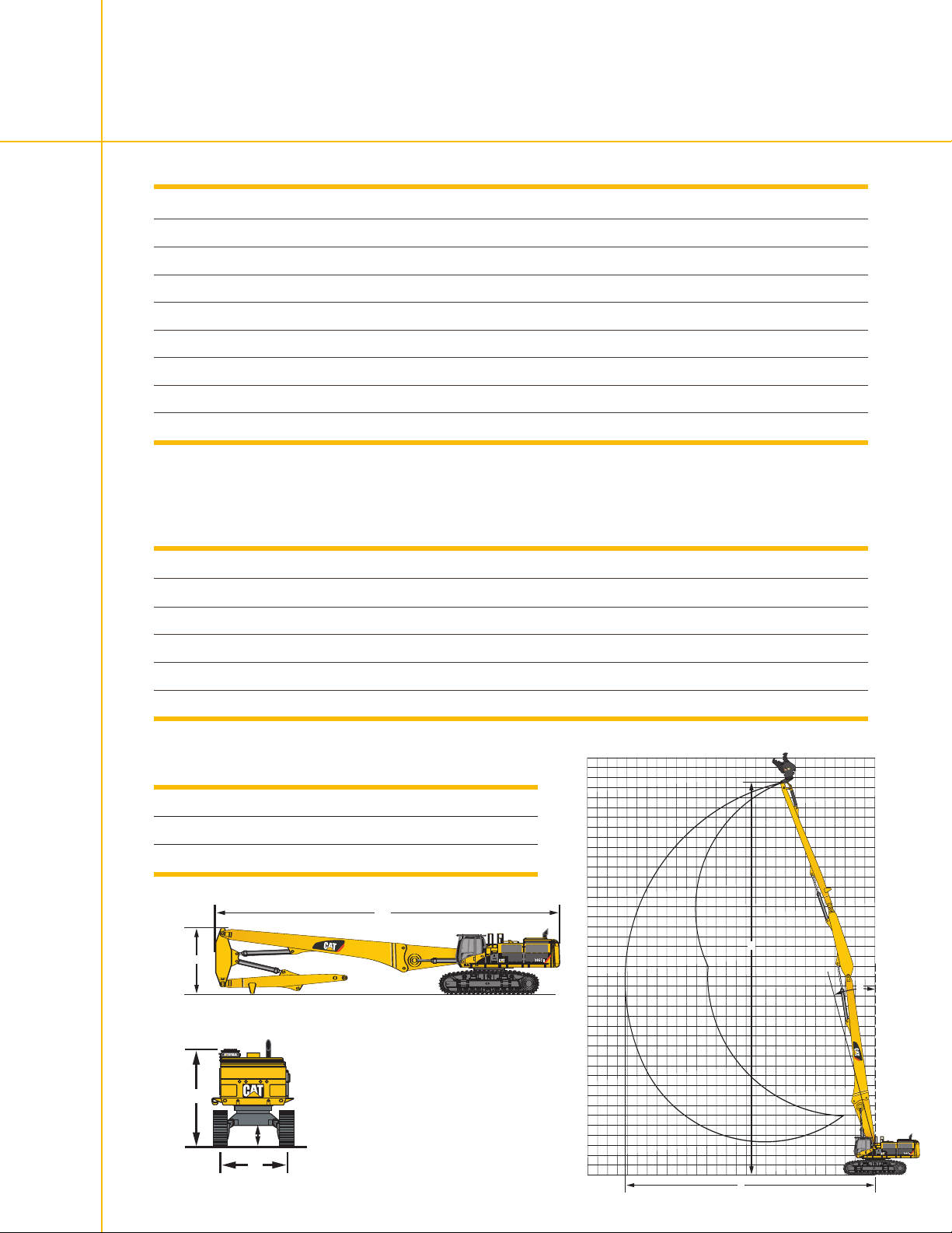
Specifications – 385C (40 m)
A
B
D
C
E
Dimensions and Weights
UHD Version
Storage Length
A
Boom Height
B
Cab Height (with FOGS)
C
Shipping Gauge (retracted position)
D
Working Gauge (extended position)
D
Ground Clearance
E
Machine Weight (UHD configuration) *
Machine Weight (Retrofit Configuration) **
* Without tool
** May vary depending on the stick and the bucket
Working Range
UHD Version
Maximum allowable angle from vertical
A
Maximum Horizontal Reach
B
Maximum Pin Height
C
40 m
m/in 22 710/894
m
m/in 8120/320
m
m/in 3950/156
m
mm/in 2750/108
mm/in 3510/138
mm/in 890/35
kg/lb 98 720/217,640
kg/lb 93 730/206,639
40 m
15°
mm/in 25 200/992
mm/in 39 500/1,555
Maximum Tool Weight (over the front)
Maximum Tool Weight (over the side)
kg/lb 2400/5,291
kg/lb 2100/4,630
Example: 385C – 40 m version
Engine Specs
Engine Cat C18 with ACERT™ Technology
Ratings
Net Power (ISO 9249)
rpm 1800
kW/hp 390/530
Dimensions and weights
Working range
15
Page 16

Main Standard Equipment
Standard on all Cat UHD Models
Reinforced upper frame and heavier counterweight
•
• Hydraulically tiltable cab (integrated into the upper frame)
• Purpose-designed demolition cab, with impact-resistant front
windshield, large high-resistant upper skylight, and FOGS
• Front windshield and top window wipers
• Boom Hook System with Hydraulic Quick Disconnects
(330D) or face-to-face ball valves (345C, 365C, 385C)
• Tool cylinder protection guard (sliding steel box)
• Dedicated UHD tool linkage
• Boom, stick and tool cylinder lowering control devices with Caterpillar
SmartBoom™ system and overload warning device
16
Page 17
Work Tools
The right work tools are critical when it comes to getting the best productivity and flexibility from a machine.
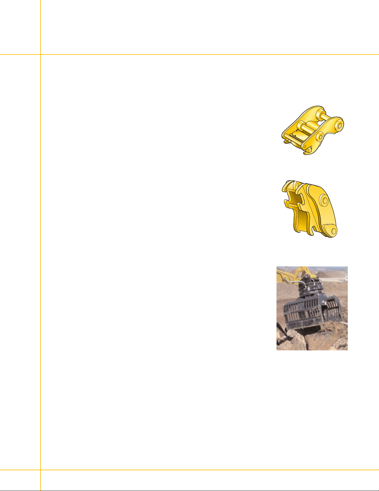
Quick Couplers
With the addition of a coupler system, exchanging work tools is fast and easy
– improving overall production, and increasing machine versatility. Couplers
can connect to a wide variety of work tools including Grapples, Shears, and
Multi-processors
Dedicated Coupler
Equipped with an integrated 50mm lifting-eye, the coupler can handle
material without a tool attached, maximizing available lifting power. The
Dedicated Coupler system is available in both manual and hydraulic
configurations.
Pin Grabber Plus Quick Coupler
The basic mechanism is a double-acting hydraulic cylinder that moves a
hook to engage or disengage the pin of the work tool. Two check valves and
a redundant mechanical locking system called the blocking bar prevent tool
disengagement in the event of a hose or hydraulic system failure. Release of
the work tool is only possible when the tool and stick are in the full curl
position and the hydraulic cylinder is purposely retracted to disengage the
hook from the pin.
Dedicated Coupler
Pin Grabber Plus Quick Coupler
Sorting and Demolition Grapples
Productive in Demolition
Sorting and Demolition grapples can either grab large piles of material, or
pinch individual items between the jaw tips. Speed, dexterity and clamping
force of these grapples make them ideal for demolition of non-concrete
structures. Steel plates bolted on to the sides of the grapple are available as
an option when loading operations require the ends be closed off.
Easily Positioned and Maneuvered
With 360° hydraulic rotation, quick rotation speed, and control accuracy the
operator can start and stop rotation instantaneously. The tool can turn a full
360 degrees in four seconds. A positive, mechanical linkage between the
stick and the grapple allows the grapple to be accurately positioned almost
anywher
Built for Durability
Cutting edges are made of Hardox 5000 and ar
1-inch thick bolt-on wear plates. Wear plates are made with the proprietary
Cat DH2 steel which has excellent impact and abrasion r
a hardness approaching 50 RC. These wear plates can be turned 180 degrees
– doubling the life of the wear plates. Two welded-on horizontal steel bars on
each jaw reinforce the vertical ribs. Hydraulic cylinders are fully protected.
e within r
each of the excavator.
otected on the outside by
e pr
esistance, as well as
17
Page 18
Work Tools
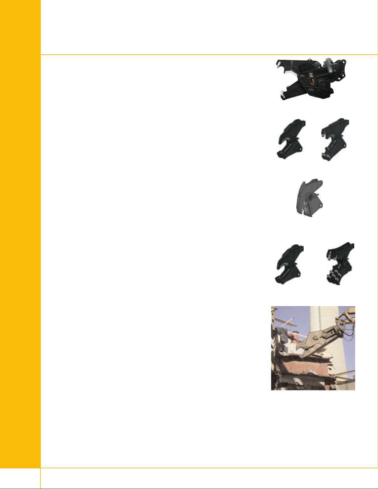
Multi-Processors
Extreme Versatility
Multi-Processor housings can be equipped with one of six purpose-built
interchangeable jaw sets. Because of a conveniently placed lifting eye and
only two stop bolts to remove, jaw sets can be interchanged quickly.
Wherever possible, replacement parts are common across jaw types.
Maximum Productivity
A single cross-mounted cylinder provides exceptional cutting and crushing
force. Productivity is maximized with a speed valve, which reduces jaw cycle
time. Continuous 360° rotation positions the grapple while minimizing the
need to move the machine. Compact design puts the most power in the
smallest package for a lower total system cost.
Durable Work Tool
Multi-Processors are built tough to endure cutting, crushing and pulverizing
thick, heavy-duty concrete and steel structures. Jaw teeth and cutting edges
are made of high quality steel with outstanding tensile strength to withstand
high cutting and crushing forces. Most jaw sets have replaceable wear
plates, increasing tool life. All jaw teeth are designed to minimize wear in
continuous demolition applications and are cast instead of fabricated.
aw sets can be quickly interchanged.
J
hear (S)
S
Tank Shear (TS)
oncrete Cutter (CC)
C
Low Noise Level
Even though Multi-Processors offer greater force and fast jaw movement,
they are non-impact tools and work at a relatively low noise level.
Mobile Shears
Complete Solution
Mobile shears are built to demolish and recycle steel structures and are
designed to be compatible with a matching Cat machine. Bolt-on brackets
are offered, adding versatility and reach, and proven hydraulic components
es and flows in demolition applications. Together Cat
handle the high pr
hydraulic kits, shears and machines make a complete system solution.
360° Rotation, Efficient Jaw Design, Fast Cycle Times
A bi-directional slewing ring rotation system allows the operator to quickly
and precisely place jaws for cutting, reducing the need to move the
excavator. Rhomboid-shaped knife design improves wire-cutting
performance. Hardened piercing tip of the upper jaw penetrates material,
maximizing productivity. Straight-line knife position in lower jaw increases
fective shear force. Steel is compressed and flattened for a more effective,
ef
clean cut. An adjustable hub reduces the need for shimming the knives in the
lower jaw. Integrated speed valve reduces cycle time, for mor
essur
e cuts per hour.
Crusher (CR)
Mobile Shears
Primary Pulverizer
(PP)
18
Built Durable
A unique knife r
etention system pr
events bolt shearing. Bushings lock cutters
in place, eliminating bending loads on bolts. Fully reversible, high-hardness
knives maintain their edge for long life and have four cutting edges each.
Page 19
Specifications – Work Tools
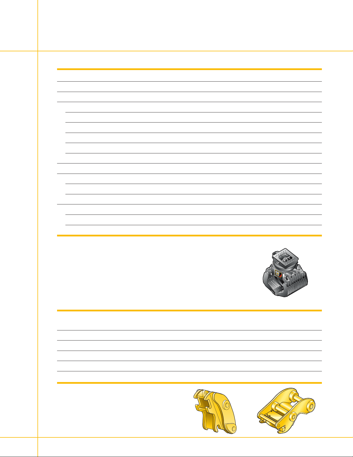
Grapples
pecifications
S
Weight
Capacity
Dimensions
Length (grapple closed)
Length (grapple open)
Width
Height (grapple closed)
Height (grapple open)
Closing force
Maximum Oil Flow
Hydraulic cylinder
Rotation
Maximum Working Pressure
Hydraulic cylinder
Rotation
* Includes mounting bracket
315 G320
G
kg/lb 1840/4,057* 2060/4,542*
Liter/gal 800/211 900/238
mm/in 1505/59 1505/59
mm/in 2265/89 2265/89
mm/in 1115/44 1394/55
mm/in 1850/73 1850/73
mm/in
kN/lbf 60/13,489 60/13,489
l/min/gpm 100/26 100/26
l/min/gpm 40/11 40/11
bar/psi 350/5,076 350/5,076
bar/psi 140/2,031 140/2,031
1690/67 1690/67
Quick Couplers
Specifications
Pin Grabber Plus Hydraulic Quick Coupler
Linkage
Weight, with pins (kg/lb)
Dedicated Coupler (hydraulic)
Linkage
Weight, with pins (kg/lb)
C D CB DB TB VB HB
510/1,124 568/1,252 576/1,270 644/1,420 855/1,885 985/2,172 1455/3,208
C D CB DB TB VB HB
302/666
292/644
339/747 342/754 523/1,153 1228/2,707 1315/2,899
19
Page 20
Specifications – Work Tools
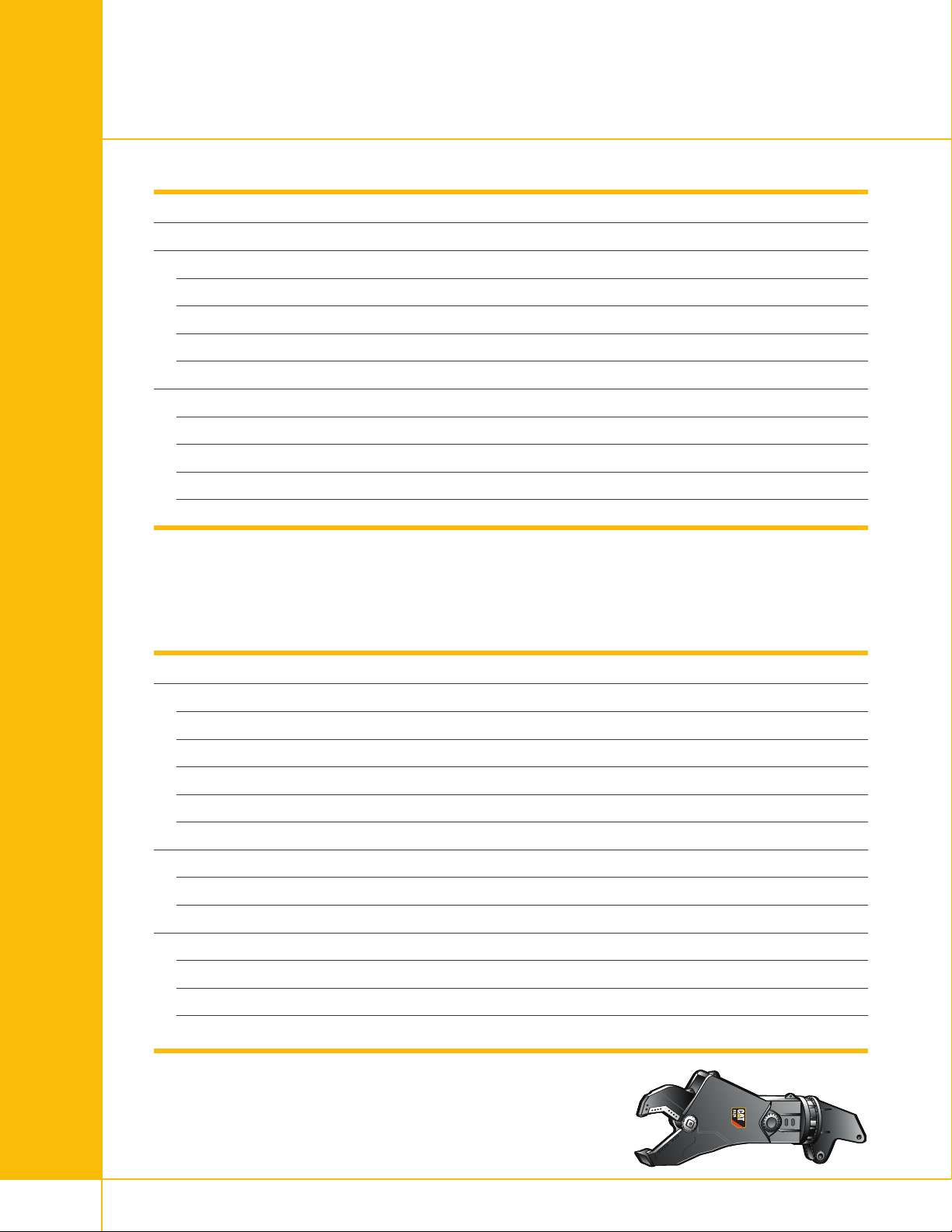
Shear Specifications
Specifications
eight
W
imensions
D
Length
Height
Jaw opening
Jaw depth
Shear Force
At tip
Apex
At throat
P
max
Hydraulic Requirements
S320 S325
g/lb 2150/4,740 3000/6,614
k
mm/in 3044/120 3453/136
mm/in 1183/47 1374/54
mm/in 390/15 490/19
mm/in 440/17 570/22
kN/lbf 891/200,305 1274/286,407
kN/lbf 1553/349,128 2200/494,580
kN/lbf 3340/750,862 5415/1,217,340
bar/psi 350/5,076 350/5,076
Specifications
Hydraulic for cutting
Optimum flow
Return flow (opening)
Speed open
Speed close
Connection
Speed valve
Switching pressure
Oil flow (max)
Hydraulic for rotating
P
max
Optimum flow
omotor
Hydr
S320 S325
l/min/gpm 150/40 200/53
l/min/gpm 240/63 300/79
sec
sec
BSP 1 1
bar/psi 200/2,901 200/2,901
l/min/gpm 200/53 300/79
l/min/gpm
l/min/gpm 40/11 40/11
45
3
140/37
one
140/37
one
3
20
Page 21
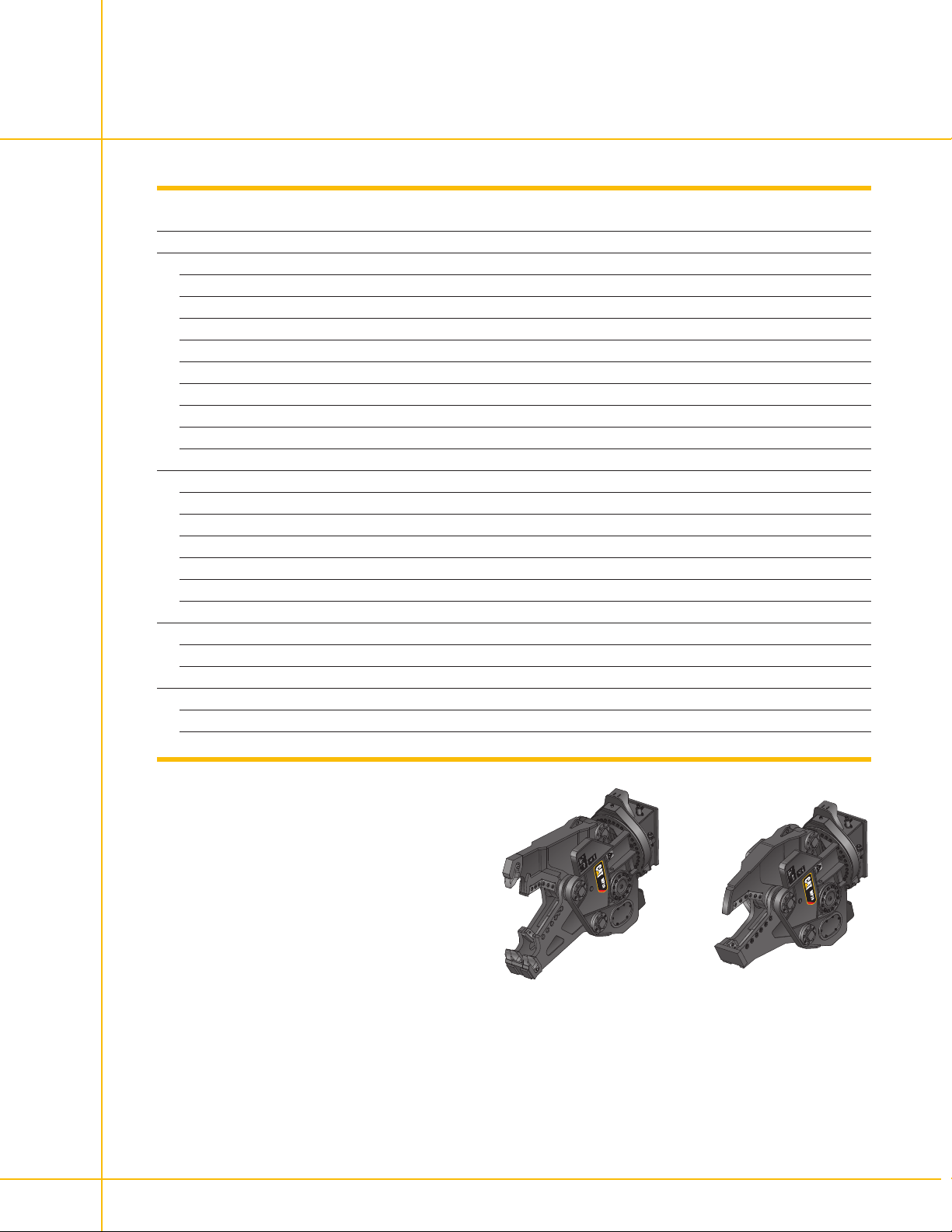
Concrete Cutter Jaws
and Shear Jaws
Specifications and Dimensions
Weight: housing, jaw, bracket
Dimensions
Length
Height
Width
Fixed Jaw width
Moving Jaw width
Jaw opening
Jaw depth
Cutter length
Cycle time
Arm Torque
Fully Open
Fully Closed
Cutting/Crushing Force
Tooth-jaw tip
Primary blade center
At throat
Hydraulic Requirements, cutting circuit
Max. Operating Pressure
Max. Oil Flow
Hydraulic Requirements, rotation circuit
Max. Operating Pressure
Max. Oil Flow
kg/lb 1950/4,299 2570/5,666 3890/8,576 2020/4,453 2660/5,864 3850/8,488
mm/in 2100/83 2250/89 2700/106 2200/87 2400/94 2800/110
mm/in 1310/52 1510/59 1680/66 1510/59 1750/69 1980/78
mm/in 800/31 800/31 1010/40 800/31 800/31 1010/40
mm/in 300/12 320/13 370/15 300/12 360/14 380/15
mm/in 80/3 100/4 120/5 100/4 130/5 130/5
mm/in 390/15 420/17 470/19 670/26 820/32 975/38
mm/in 480/19 580/23 710/28 670/26 790/31 890/35
mm/in 400/16 520/20 600/24 400/16 460/18 520/20
sec 5 6 6.5 5 6 6.5
kN•m/lb•ft 547/403,446 882/650,529 1348/994,232 525/387,220 844/622,502 1257/927,114
kN•m/lb•ft 378/278,798 563/415,247 907/668,968 342/252,246 502/370,256 759/559,809
kN/lbf 900/202,328 1200/269,771 1600/359,694 700/157,366 950/213,569 1250/281,011
kN/lbf 2100/472,099 2900/651,946 3750/843,034 1000/224,809 1400/314,733 1850/415,897
kN/lbf 4200/944,198 5800/1,303,892 7100/1,596,143 2200/494,580 3000/674,427 4100/921,717
kPa/psi 35 000/5,076 35 000/5,076 35 000/5,076 35 000/5,076 35 000/5,076 35 000/5,076
l/min/gpm 150/40 200/53 300/79 150/40 200/53 300/79
kPa/psi 14 000/2,031 14 000/2,031 14 000/2,031 14 000/2,031 14 000/2,031 14 000/2,031
l/min/gpm 40/11 40/11 40/11 40/11 40/11 40/11
P15 MP20 MP30 MP15 MP20 MP30
Shear Jaws Concrete Cutter Jaws
M
21
Page 22
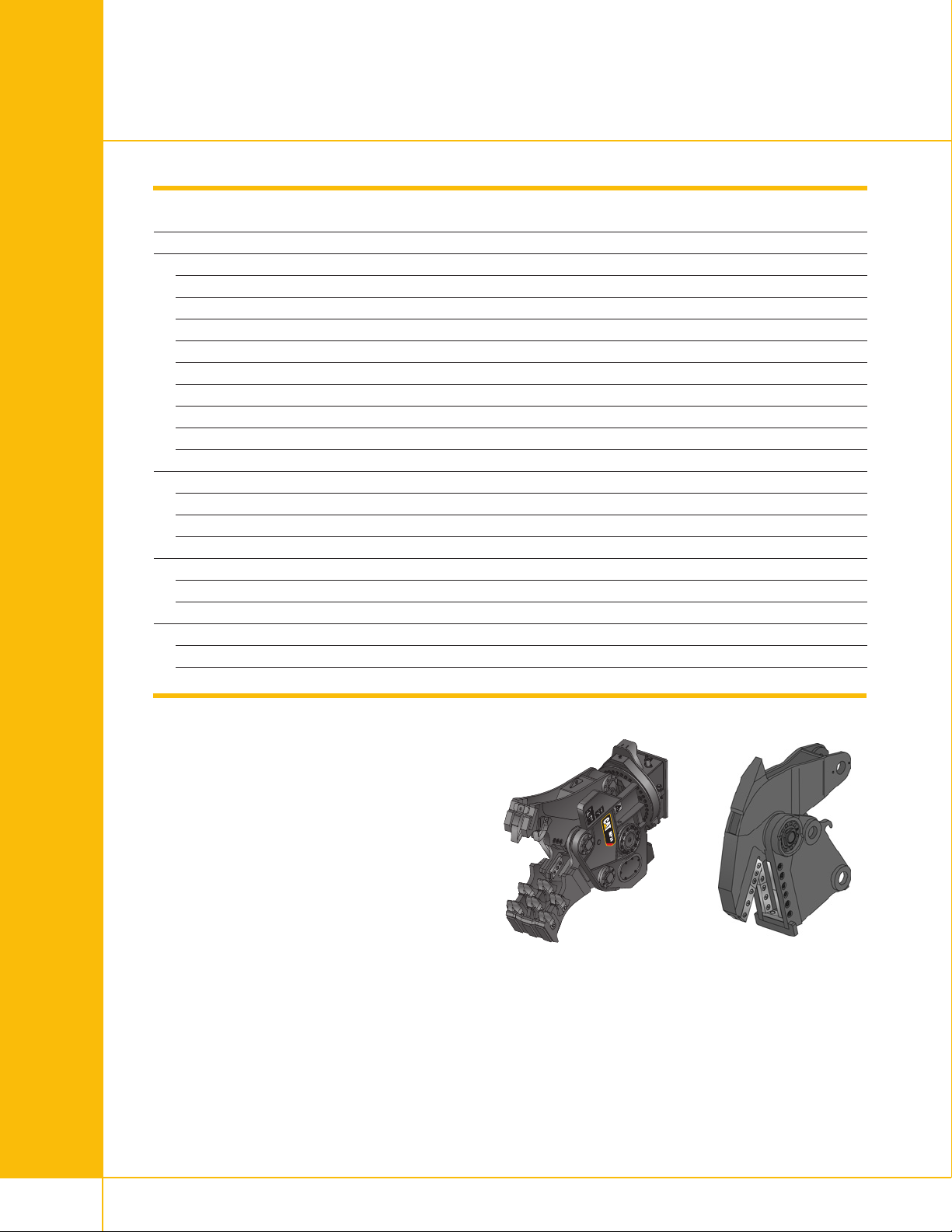
Tank Shear Jaws
and Crusher Jaws
Specifications and Dimensions
eight: housing, jaw, bracket
W
Dimensions
Length
eight
H
Width
Fixed Jaw width
Moving Jaw width
Jaw opening
Jaw depth
Cutter length
Cycle time
Cutting/Crushing Force
Tooth-jaw tip
Primary blade center
At throat
Hydraulic Requirements, cutting circuit
Max. Operating Pressure
Max. Oil Flow
Hydraulic Requirements, rotation circuit
Max. Operating Pressure
Max. Oil Flow
kg/lb 2740/6,041 4380/9,656 2010/4,431 2660/5,864 3860/8,510
mm/in 2400/94 2800/110 2200/87 2350/93 2770/109
mm/in 1750/69 2100/83 1310/52 1750/69 1980/78
mm/in 800/31 1180/46 800/31 800/31 1010/40
mm/in 290/11 340/13 300/12 360/14 380/15
mm/in 120/5 150/6 100/4 130/5 130/5
mm/in 440/17 510/20 710/28 850/33 1050/41
mm/in 460/18 580/23 700/28 770/30 920/36
mm/in 460/18 580/23 200/8 260/10 260/10
sec 6 6.5 5 6 6.5
kN/lbf 1400/314,733 1900/427,137 700/157,366 950/213,569 1250/281,011
kN/lbf 2200/494,580 4000/899,236 950/213,569 1350/303,492 1750/393,416
kN/lbf 4400/989,159 6350/1,427,537 2100/472,099 2900/651,946 3800/854,274
kPa/psi 35 000/5,076 35 000/5,076 35 000/5,076 35 000/5,076 35 000/5,076
l/min/gpm 200/53 200/53 150/40 200/53 300/79
kPa/psi 14 000/2,031 14 000/2,031 14 000/2,031 14 000/2,031 14 000/2,031
l/min/gpm 40/11 40/11 40/11 40/11 40/11
Tank Shear Jaws Crusher Jaws
MP20 MP30 MP15 MP20 MP30
22
Page 23
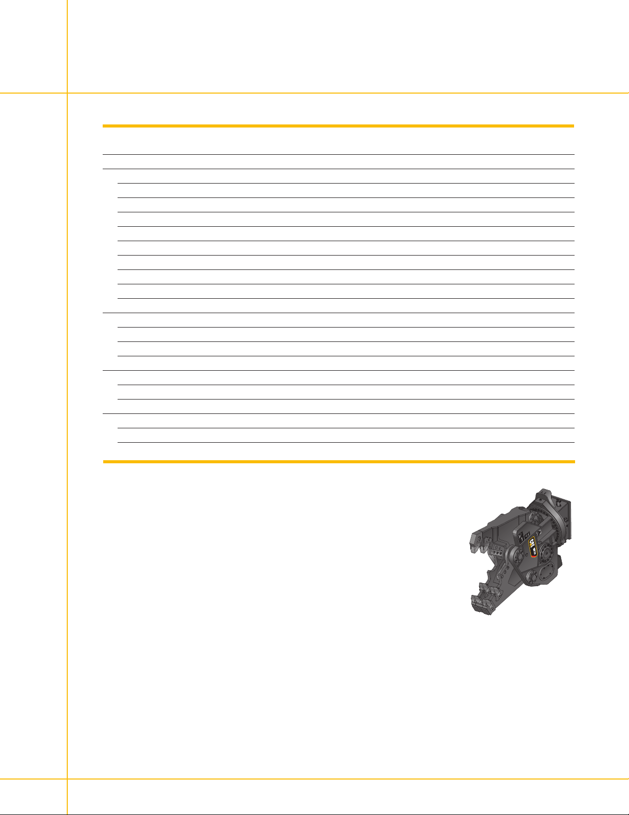
Primary Pulverizer Jaws
Specifications and Dimensions
Weight: housing, jaw, bracket
Dimensions
ength
L
Height
Width
Fixed Jaw width
Moving Jaw width
Jaw opening
Jaw depth
Cutter length
Cycle time
Cutting/Crushing Force
Tooth-jaw tip
Primary blade center
At throat
Hydraulic Requirements, cutting circuit
Max. Operating Pressure
Max. Oil Flow
Hydraulic Requirements, rotation circuit
Max. Operating Pressure
Max. Oil Flow
l/min/gpm 150/40 200/53 300/79
l/min/gpm 40/11 40/11 40/11
rimary Pulverizer Jaws
P
P15 MP20 MP30
M
kg/lb 2220/4,894 2900/6,393 4180/9,215
mm/in 2220/87 2325/92 2800/110
mm/in 1590/63 1775/70 1980/78
mm/in 800/31 800/31 1010/40
mm/in 480/19 540/21 610/24
mm/in 280/11 340/13 370/15
mm/in 700/28 800/31 960/38
mm/in 700/28 800/31 940/37
mm/in 200/8 200/8 250/10
sec 5 6 6.5
kN/lbf 650/146,126 950/213,569 1250/281,011
kN/lbf 900/202,328 1300/292,252 1550/348,454
kN/lbf 2100/472099 2750/618,225 3950/887,995
kPa/psi 35 000/5,076 35 000/5,076 35 000/5,076
kPa/psi 14 000/2,031 14 000/2,031 14 000/2,031
23
Page 24

www.cat.com
e complete infor
For mor
services, and industry solutions, visit us on the web at
www.cat.com
© 2007 Caterpillar
All Rights Reserved
Materials and specifications ar
Featured machines in photos may include additional equipment.
See your Caterpillar dealer for available options.
CAT, CATERPILLAR, ACERT, their respective logos, “Caterpillar Yellow,” and the
POWER EDGE trade dress, as well as corporate and product identity used herein,
are trademarks of Caterpillar and may not be used without permission.
AEXQ0157 (3-07)
mation on Cat products, dealer
e subject to change without notice.
 Loading...