

Page 1
SCHEMATIC FEATURES AND TIPS
Make sure your Adobe Acrobat Reader is up
to date in order to access the latest features
of this schematic.
GET
Adobe Acrobat Reader
SAVE
a copy of this schematic
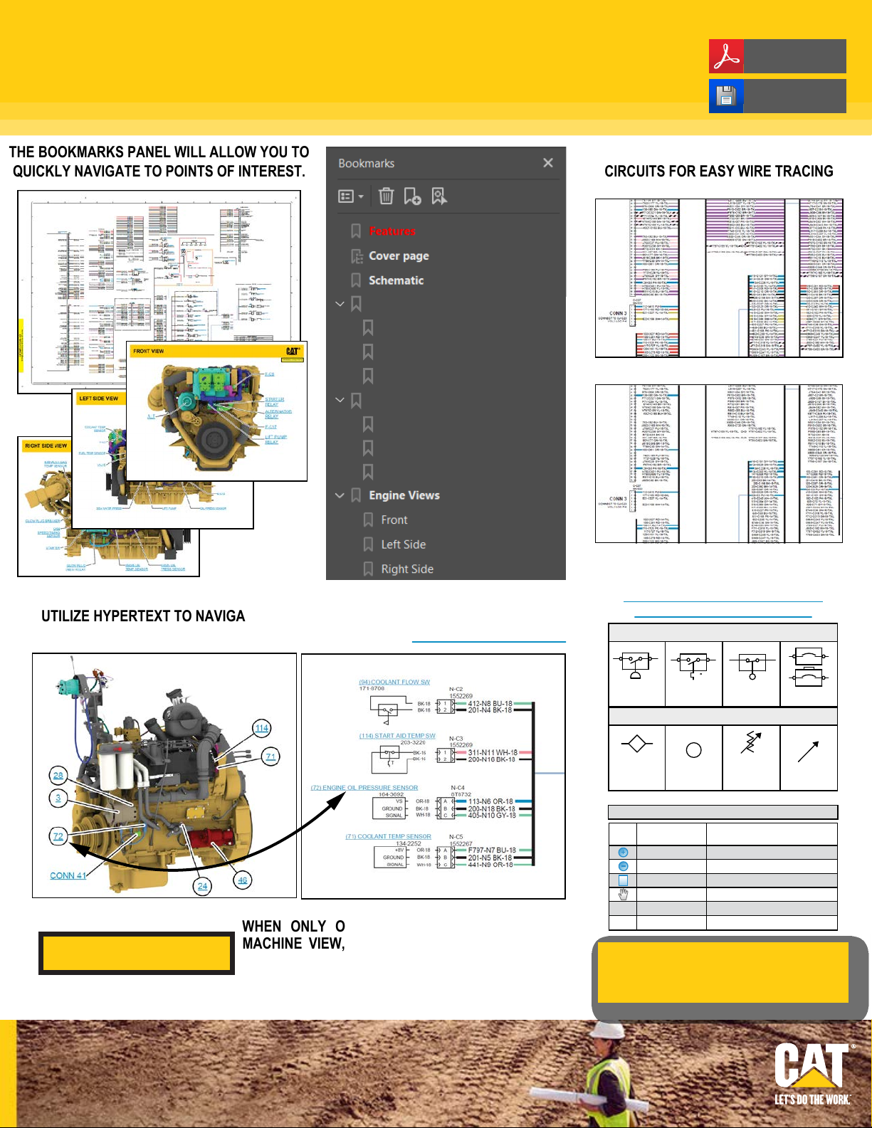
THE BOOKMARKS PANEL WILL ALLOW YOU TO
QUICKLY NAVIGATE TO POINTS OF INTEREST.
Function Isolation Tools
Grids On/Off
All Circuits Off
All Circuits On
Vol 1 - Cab Wiring
032 (Red) (Battery Power)
640 (Blue) (Key Power)
021 (Orange) (Starting)
THE FUNCTION ISOLATION TOOLS ISOLATE
CIRCUITS FOR EASY WIRE TRACING
STANDARD VIEW
640 (Blue) (Key Power) CIRCUIT ISOLATED
UTILIZE HYPERTEXT TO NAVIGATE TO COMPONENTS AND THEIR MACHINE LOCA-
TION QUICKLY. HYPERTEXT IS INDICATED BY TEXT THAT IS BLUE AND UNDERLINED.
WHEN ONLY ONE CALLOUT IS SHOWING ON A
VIEW ALL CALLOUTS
MACHINE VIEW, CLICKING ON THIS BUTTON WILL
MAKE ALL OF THE CALLOUTS VISIBLE. THIS
BUTTON IS TYPICALLY LOCATED IN THE TOP RIGHT
CORNER OF EVERY MACHINE VIEW PAGE.
CLICK HERE TO VIEW THE SCHEMATIC
SYMBOLS AND DEFINITIONS PAGE
ELECTRICAL SYMBOLS
Pressure
Switch
T
Temperature
Switch
Level
Switch
Circuit Breaker
BASIC HYDRAULIC SYMBOLS
Fluid
Conditioner
Due to different monitor sizes and PDF reader
preferences there may be some variance in linked
schematic locations. This document is best viewed at
a screen resolution of 1024 X 768.
Pump
or Motor
HOTKEYS (Keyboard Shortcuts)
FUNCTION
Zoom In
Zoom Out
Fit to Page
Hand Tool
Find
Search
Spring
(Adjustable)
“CTRL” / “+”
“CTRL” / “-”
“CTRL” / “0” (zero)
“SPACEBAR” (hold down)
“CTRL” / “F”
“CTRL” / “SHIFT” / “F”
Variability
KEYS
© 2022 Caterpillar. All Rights Reserved. CAT, CATERPILLAR, LET’S DO THE
WORK, their respective logos, “Caterpillar Corporate Yellow”, the “Power Edge”
and Cat “Modern Hex” trade dress as well as corporate and product identity used
herein, are trademarks of Caterpillar and may not be used without permission.
Page 2
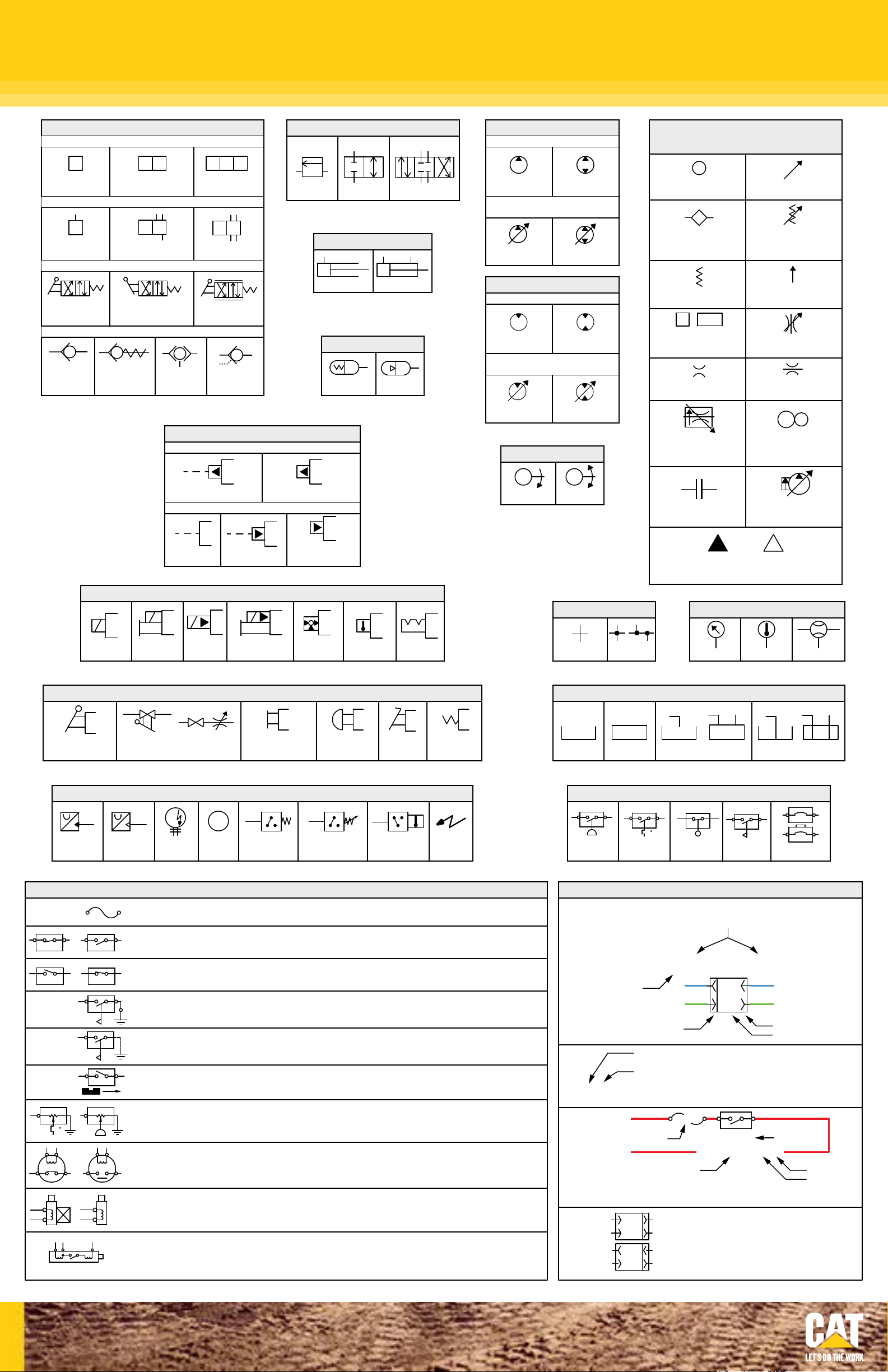
SCHEMATIC SYMBOLS AND DEFINITIONS
One Position
Two-way
A B
P T
Normal Position
Basic
Symbol
VALVES
ENVELOPES
Two Position
PORTS
Three-Way
CONTROL
A B
P T
Shifted Position
CHECK
Spring
Loaded
Shuttle
Three Position
Four-Way
Infinite Position
Pilot
Controlled
PILOT CONTROL
RELEASED PRESSURE
INTERNAL PASSAGEWAYS
FLOW IN ONE
DIRECTION
Infinite
Positioning
FLOW ALLOWED IN
EITHER DIRECTION
Two
Position
CYLINDERS
Single Acting
Double Acting
ACCUMULATORS
Spring Loaded
Gas Charged
PARALLEL
FLOW
Three
Position
CROSS
FLOW
PUMPS
FIXED DISPLACEMENT
Unidirectional
Bidirectional
VARIABLE DISPLACEMENT
NON- COMPENSATED
Unidirectional
Bidirectional
MOTORS
FIXED DISPLACEMENT
Unidirectional
Bidirectional
VARIABLE DISPLACEMENT
NON- COMPENSATED
Unidirectional
Bidirectional
ROTATING SHAFTS
BASIC HYDRAULIC
COMPONENT SYMBOLS
Pump
or Motor
Fluid
Conditioner
Spring
Control
Valves
Restriction
Line Restriction
Variable and Pressure
Compensated
Variability
Spring
(Adjustable)
Pressure
Compensation
Line Restriction
(Variable)
Line Restriction
(Fixed)
AUX.
MAIN
2-Section
Pump
External Return
Simplified
Solenoid
Push-pull Lever PedalGeneral Manual Push Button SpringManual Shutoff
Solenoid
or Manual
Solenoid
and Pilot
HYDRAULIC SYMBOLS - ELECTRICAL
Internal Return
REMOTE SUPPLY PRESSURE
Complete
Internal
Supply Pressure
COMBINATION CONTROLS
Solenoid and
Pilot or Manual
Servo
MANUAL CONTROL
Thermal
Detent
Unidirectional
Bidirectional
Pump: Variable and
Pressure Compensated
MEASUREMENT
Temperature
Flow
Crossing
LINES
Joining
Attachment
Hydraulic Pneumatic
Energy Triangles
Pressure
FLUID STORAGE RESERVOIRS
Vented Pressurized Return Above Fluid Level Return Below Fluid Level
ELECTRICAL SYMBOLS
Transducer
(Fluid)
T
Transducer
(Gas / Air)
G
Generator
M
Electric
Motor
Pressure
Switch
Pressure Switch
(Adjustable)
Temperature
Switch
Electrical
Wire
BASIC ELECTRICAL COMPONENT SYMBOLS
Fuse: A component in an electrical circuit that will open the circuit if too much current flows through it.
Switch (Normally Open): A switch that will close at a specified point (temp, press, etc.). The circle indicates
Switch (Normally Closed): A switch that will open at a specified point (temp, press, etc.).
Ground (Wired): This indicates that the component is connected to a grounded wire.
The grounded wire is fastened to the machine.
Ground (Case): This indicates that the component does not haveawire connected to ground.
It is grounded by being fastened to the machine.
Reed Switch: A switch whose contacts are controlled by a magnet. A magnet closes the contacts of
a normally open reed switch; it opens the contacts of a normally closed reed switch.
Sender: A component that is used with a temperature or pressure gauge.
The sender measures the temperature or pressure.
Its resistance changes to give an indication to the gauge of the temperature or pressure.
Relay (Magnetic Switch): A relay is an electrical component that is activated by electricity.
Solenoid: A solenoid is an electrical component that is activated by electricity.
It has a coil that makes an electromagnet when current flows through it.
The electromagnet can open or close a valve or move a piece of metal that can do work.
Magnetic Latch Solenoid: An electrical component that is activated by electricity and held latched by a
that the component has screw terminals and a wire can be disconnected from it.
No circle indicates that the wire cannot be disconnected from the component.
It has a coil that makes an electromagnet when current flows through it.
The electromagnet can open or close the switch part of the relay.
permanent magnet. It has two coils (latch and unlatch) that make electromagnet
when current flows through them. It also has an internal switch that places
the latch coil circuit open at the time the coil latches.
Pressure
Switch
T
Temperature
Switch
Switch
HARNESS AND WIRE SYMBOLS
Wire, Cable, or Harness Assembly Identification:
Includes Harness Identification Letters and Harness
Connector Serialization Codes (see sample).
AG-C4
Part Number: for
Connector Plug
Harness Identification Letter(s): (A, B, C, AA, AB, AC, ...)
Harness Connector Serialization Code: The "C" stands for
"Connector" and the number indicates which connector in the
harness (C1, C2, C3, ...)
L-C12
3E-5179
Fuse (5 Amps)
Harness identification code:
This example indicates wire group 325,
wire 135 in harness "AG".
1
2
1
2
111-7898
Plug
5A
*Wire gauge is shown in AWG (American Wire Gauge)
but could also be shown in metric denoted with mm
Deutsch connector: Typical representation
of a Deutsch connector. The plug contains all
sockets and the recept
Sure-Seal connector: Typical representation
of a Sure-Seal connector. The plug and receptacle
contain both pins and sockets.
Level
Flow
Switch
L-C12
3E-5179
1
2
9X-1123
325-AG135 PK-14
acle contains all pins.
Circuit Breaker
Receptacle
Pin or Socket Number
Component
Part Number
Wire Gauge*
Wire Color
© 2022 Caterpillar. All Rights Reserved. CAT, CATERPILLAR, LET’S DO THE
WORK, their respective logos, “Caterpillar Corporate Yellow”, the “Power Edge”
and Cat “Modern Hex” trade dress as well as corporate and product identity used
herein, are trademarks of Caterpillar and may not be used without permission.
Page 3

RENR1368-06
April 2022
3126B and 3126E Off-Highway Engine
Electrical System
3126B:
BKD1-UP
1AJ1-UP
8YL1-UP
8SZ1-UP
3126E:
G3E1-UP
CKM1-UP
CRP1-UP
7AS1-UP
9SZ1-UP
PUBLICATIONS.CAT.COM
© 2022 Caterpillar. All Rights Reserved. CAT, CATERPILLAR, LET’S DO THE WORK, their respective logos, “Caterpillar Corporate Yellow”, the “Power Edge”
and Cat “Modern Hex” trade dress as well as corporate and product identity used herein, are trademarks of Caterpillar and may not be used without permission.
Page 4

DIAGNOSTIC CODE LISTING
PID-FMI Description
00-00 No Detected Faults 55 0105-03 Intake Manifold Air Temperature voltage high 38
0001-11 Cylinder #1 Injector current fault 72 0105-04 Intake Manifold Air Temperature voltage low 38
0002-11 Cylinder #2 Injector current fault 72 0105-11 Very High Intake Manifold Air Temperature 64
0003-11 Cylinder #3 Injector current fault 73 0108-03 Barometric Pressure voltage high 26
0004-11 Cylinder #4 Injector current fault 73 0108-04 Barometric Pressure voltage low 26
0005-11 Cylinder #5 Injector current fault 74 0110-00 High Coolant Temperature Warning 61
0006-11 Cylinder #6 Injector current fault 74 0110-03 Coolant Temperature voltage high 27
0022-11 Primary to Secondary Engine Speed Signal Calibration 42 0110-04 Coolant Temperature voltage low 27
0022-13 Engine Speed Signal Calibration Not Performed 42 0110-11 Very High Coolant Temperature 61
0030-08 PTO Throttle signal invalid 29 0111-01 Low Coolant Level Warning 62
0030-13 PTO Throttle out of calibration 29 0111-02 Coolant Level signal invalid 12
0041-03 8 Volt Supply voltage high 21 0111-03 Coolant Level voltage high 12
0041-04 8 Volt Supply voltage low 21 0111-04 Coolant Level voltage low 12
0042-11 Injection Actuation Pressure output fault 0111-11 Very Low Coolant Level 62
0043-02 Key Switch Fault 71 0128-03 Secondary Fuel Level voltage high
0064-02 Secondary Engine Speed loss of signal 34 0128-04 Secondary Fuel Level voltage low
0064-11 Secondary Engine Speed no pattern 34 0164-00 Excessive Injection Actuation Pressure 17
0070-05 Inlet Air Heater current low 0164-02 Injection Actuation Pressure Signal Erratic 15
0070-06 Inlet Air Heater current high 0164-03 Injection Actuation Pressure voltage high 15
0071-00 Idle Shutdown Override 01 0164-04 Injection Actuation Pressure voltage low 15
0071-01 Idle Shutdown 47 0164-11 Injection Actuation Pressure system fault 39
0071-14 PTO Shutdown 47 0168-02 ECM Battery Power Intermittent 51
0084-00 Vehicle Overspeed Warning 41 0186-14 PTO Engine Shutdown Switch Occurrence 47
0084-01 Vehicle Speed loss of signal 31 0190-00 Engine Overspeed Warning 35
0084-02 Vehicle Speed signal invalid 36 0190-02 Primary Engine Speed Loss of Signal 34
0084-08 Vehicle Speed signal out of range 0190-11 Primary Engine Speed no pattern
0084-10 Vehicle Speed signal rate of change 36 0224-11 Theft Deterrent Active
0091-08 Throttle Position Invalid 32 0224-14 Theft Deterrent Active with Engine Cranking
0091-13 Throttle Position out of calibration 28 0231-02 J1939 Data Incorrect 58
0096-03 Fuel Level voltage high 0231-11 J1939 Data Link Fault 58
0096-04 Fuel Level voltage low 0231-12 J1939 Device Not Responding
0100-03 Oil Pressure voltage high 24 0232-03 5 Volt Supply voltage high 21
0100-04 Oil Pressure voltage low 24 0232-04 5 Volt Supply voltage low 21
0100-11 Very Low Oil Pressure 46 0246-11 Brake Pedal Switch #1 Fault
0102-03 Boost Pressure voltage high 25 0247-11 Brake Pedal Switch #2 Fault
0102-04 Boost Pressure voltage low 25 0252-11 Engine Software Incorrect 59
0102-07 Boost Pressure not responding 0253-02 Check Customer or System Parameters 56
0105-00 High Intake Manifold Air Temperature Warning 64 0253-14 Truck Manufacturer Parameter Not Programmed
Flash
Codes
PID-FMI Description
Flash
Codes
Page 5

ECM CONNECTOR
ECM Connectors
ECM Side
ECM Side
ECM Connector P2
HarnesECM Connector P1
DT Connector Receptacle DT Connector Plug
Receptacle Wedge
Plug Wedge
s Side
Harness Side
6 HEUI Injectors
Injection Actuation Pressure Control Valve
(IAPCV)
Top Camshaft Speed/Timing Sensor
Bottom Camshaft Speed/Timing Sensor
Injection Actuation Pressure Sensor
Boost Pressure Sensor
Atmospheric Pressure Sensor
Engine
Control
Module
Caterpillar Installed
OEM Installed
Accelerator Pedal Position Sensor
Ignition Key Switch
Cruise Control On/Off &
Set/Resume Switches
Clutch and Service Brake Switches
Coolant Level Sensor
Check Engine Lamp
A/C High Pressure Switch
Cab Diagnostic Connector
- 12 V +
Batteries
Warning Lamp
Speedometer & Tachometer
45
35 55
25
65
15
5
0
85
MPH
15
20
10
75
5
30
RPM X 1000
Cooling Fan
25
Receptacle Wedge
Receptacle Wedge
HD Connector Receptacle
Pin Contact
Speed/Timing Sensor Connectors
150 Series Receptacle
Socket Contact
Plug Wedge
Plug Wedge
HD Connector Plug
Sealing Plug
IAPCV Connector
150 Series Plug
(Specific Ratings Only)
Oil Pressure Sensor
(Optional)
Oil Level Switch
(Optional)
Coolant Temperature Sensor
Intake Manifold Air Temperature Sensor
Intake Air Heater Relay
Intake Air Heater
Vehicle Speed
Sensor
PTO Accelerator
Position Sensor
Fast Idle Enabled Lamp
Or Wait To Start Lamp
Fast Idle Enable Switch
PTO Switch On Lamp
PTO On/Off & PTO
Set/Resume Switches
Transmission Neutral Switch
AT/MT/HT Transmission Relay
Exhaust Brake On/Off Switch
Exhaust Brake
Intake Air Heater Lamp
A
Page 6

RELATED ELECTRICAL SERVICE MANUALS
Title
Troubleshooting
Systems Operation / Testing and Adjusting
Form Number
RENR1367
RENR1271
Page 7

67
3126B & 3126E ENGINE ELECTRICAL SCHEMATIC
INJECTOR HARNESS GROMMET
12345
F
E
D
L983-WH
J301 P301
B
F7 F6 F5 F4 F3 F2 F1
A
INJECTOR
CYLINDER
NO.1
ENGINE ATMOSPHERIC
ENGINE BOOST
PRESSURE
SENSOR
ENGINE INJECTION
ACTUATION
PRESSURE
SENSOR
PRESSURE
SENSOR
A701-GY
NOTE A
J302 P302
B
A
INJECTOR
CYLINDER
NO.2
E7
ENGINE OIL
PRESSURE
SENSOR
NOTE A
ENGINE OIL LEVEL
SWITCH
NOTE A
ENGINE COOLANT
TEMPERATURE
SENSOR
ENGINE INTAKE
MANIFOLD AIR
TEMPERATURE
SENSOR
D7
L983-WH
B
A
INJECTOR
CYLINDER
NO.3
A702-PU
ENGINE BOOST PRESSURE
ENGINE PRESSURE SENSOR RETURN
ENGINE PRESSURE SENSOR +5V
ENGINE INJECTION ACTUATION PRESSURE
ENGINE PRESSURE SENSOR RETURN
ENGINE PRESSURE SENSOR +5V
ENGINE ATMOSPHERIC PRESSURE
ENGINE PRESSURE SENSOR RETURN
ENGINE PRESSURE SENSOR +5V
E6
ENGINE OIL PRESSURE SENSOR
ENGINE OIL PRESSURE SENSOR RETURN
ENGINE OIL PRESSURE SENSOR +5V
ENGINE OIL LEVEL
ENGINE OIL LEVEL RETURN
ENGINE COOLANT TEMPERATURE
ENGINE TEMPERATURE SENSOR RETURN
ENGINE INTAKE MANIFOLD AIR TEMPERATURE
ENGINE TEMPERATURE SENSOR RETURN
D6
L984-OR
A703-BR
C
B
A
C200
C
B
A
C204
C203
C
B
A
C201
C
B
A
J304 P304J303 P303
B
A
INJECTOR
CYLINDER
NO.4
A746-PK
G829-GN
G828-WH
G849-BR
G829-GN
G828-WH
A747-GY
G829-GN
G828-WH
994-GY
G827-BU
G826-BR
1
2
J802 P802
1
2
J100 P100
1
2
J103 P103
G458-GY
�G829-GN
995-BU
G833-PK
C967-BU
G833-PK
L984-OR
B
A
INJECTOR
CYLINDER
NO.5
A704-GN
E5
TO ENGINE CYLINDER HEAD
(NOT CYLINDER HEAD GROUND STUD)
GROUND STUD
D5
L985-YL
J306 P306J305 P305
B
A
INJECTOR
CYLINDER
NO.6
A705-BU
TOP CAMSHAFT ENGINE
SPEED/TIMING SENSOR
BOTTOM CAMSHAFT ENGINE
SPEED/TIMING SENSOR
INTAKE AIR
L985-YL
A706-GY
INJECTION ACTUATION
PRESSURE CONTROL VALVE
TOP CAMSHAFT SPEED/TIMINGTOP CAMSHAFT SPEED/TIMING+
BOTTOM CAMSHAFT SPEED/TIMINGBOTTOM CAMSHAFT SPEED/TIMING+
ENGINE TIMING CALIBRATION PROBE+
ENGINE TIMING CALIBRATION PROBE-
K995-OR
HEATER
(IAPCV)
INTAKE AIR HEATER
RELAY
P300 J300
J501 P501
1
2
12
11
10
9
8
7
6
5
4
3
2
1
A
B
J500 P500
E4
A
B
J401 P401
A
B
J402 P402
A
B
J400 P400
C987-RD
G850-BU
ENGINE HARNESS CONNECTOR
L983-WH
L984-OR
L985-YL
A706-GY
A705-BU
A704-GN
A703-BR
A702-PU
A701-GY
G854-PK
G855-PU
A746-PK
G849-BR
A747-GY
G829-GN
G828-WH
994-GY
G827-BU
G826-BR
G883-GN
G458-GY
995-BU
C967-BU
G833-PK
E963-BK
E964-WH
E965-BU
E966-YL
G856-WH
G857-YL
NOTE A
G850-BU
D4
P648
G850-BU
B
C987-RD
A
P2 J2
INJECTOR RETURN CYLINDERS 1 & 2
44
INJECTOR RETURN CYLINDERS 3 & 4
45
INJECTOR RETURN CYLINDERS 5 & 6
46
INJECTOR CYLINDER 6
55
INJECTOR CYLINDER 5
54
INJECTOR CYLINDER 4
39
INJECTOR CYLINDER 3
38
INJECTOR CYLINDER 2
37
INJECTOR CYLINDER 1
36
47
67
68
1
63
64
4
5
IAP CONTROL VALVE
61
IAP CONTROL VALVE RETURN
62
70
40
ENGINE BOOST PRESSURE
27
ENGINE INJECTION ACTUATION PRESSURE
6
7
ENGINE ATMOSPHERIC PRESSURE
14
ENGINE PRESSURE SENSOR RETURN
3
ENGINE PRESSURE SENSOR +5V
2
15
16
17
ENGINE OIL PRESSURE SENSOR
24
ENGINE OIL PRESSURE SENSOR RETURN
42
41
ENGINE OIL PRESSURE SENSOR +5V
25
51
52
53
INPUT #16
60
ENGINE OIL LEVEL SWITCH
33
32
ENGINE COOLANT TEMPERATURE
35
ENGINE INTAKE MANIFOLD AIR TEMPERATURE
9
34
26
18
ENGINE TEMPERATURE SENSOR RETURN
10
11
12
TOP CAMSHAFT SPEED/TIMING-
49
TOP CAMSHAFT SPEED/TIMING+
48
13
50
19
BOTTOM CAMSHAFT SPEED/TIMING-
59
BOTTOM CAMSHAFT SPEED/TIMING+
58
28
29
30
31
43
ENGINE TIMING CALIBRATION PROBE+
22
ENGINE TIMING CALIBRATION PROBE-
23
56
57
65
66
69
20
21
INTAKE AIR HEATER RELAY
8
ENGINE CONTROL MODULE
ECM GROUND STRAP
TO ECM
MOUNTING
BOLT
E3
D3
E2
D2
E1
D1
F
E
D
C
B
(Dimensions: 25 inches x 24 inches)
RENR1368-06
12 Page,
A
CIRCUITS WITHIN THIS AREA ARE RECOMMENDATIONS
ENGINE
BLOCK
KEY SWITCH
ALTERNATOR
GROUND
NOTE A
NOTE A
NOTE A
NOTE A
NOTE A
NOTE A
NOTE A
C7
B7
COMPONENTS WITHIN THIS AREA ARE CATERPILLAR PROVIDED
A7
RELAY
OFF
ON
START
STARTER
MOTOR
(12V)
-
12V
BATTERY 3 BATTERY 1
NOTE A
(PEDAL RELEASED POSITION)
ACCELERATOR PEDAL SENSOR/SWITCH SENSOR RETURN
-
+ +
12V
BATTERY 2
H795-PK
CRUISE CONTROL ON/OFF SWITCH
CLUTCH PEDAL POSITION SWITCH N/C
H795-PK
A/C HIGH PRESSURE SWITCH N/C
H795-PK
ACCELERATOR PEDAL POSITION
SENSOR ACCELERATOR
PEDAL POSITION
C6
-
12V
TO ALLISON AT/MT/HT SHIFT
MODULATOR FOR AUTOMATIC
TRANSMISSIONS
B6
C975-WH
A6
3126B & 3126E OEM VEHICLE ELECTRICAL SCHEMATIC
N/O
+
(PEDAL RELEASED POSITION)
C977-BU
E971-GN
+8 V
100A WITH 130A PEAK AT 11V
K995-OR
C987-RD
H795-PK
SET/RESUME SWITCH
SERVICE BRAKE PEDAL POSITION SWITCH N/C
H795-PK
DIAGNOSTIC ENABLE SWITCH
H795-PK
N/O MOMENTARY SWITCH
B
BK
RD
WH
A
C
J403 P403
H795-PK
C985-BU
C986-BR
C992-PU
G844-PK
CHECK ENGINE
LAMP
WARNING LAMP
FAST IDLE
ENABLED LAMP
OR
WAIT TO
START LAMP
EXHAUST BRAKE
SOLENOID
J1939 SHIELD
C978-BR
C979-OR
INTAKE AIR
HEATER LAMP
C987-RD
L994-YL
659-PK
C5
G880-PK
FLYBACK
DIODE
9 PIN CAB
CONNECTOR
+BAT.
B
-BAT.
A
J
H
J1587 -
G
J1587 +
F
E
J1939 -
D
J1939 +
C
NOTE A
20A
B5
+BAT.
+BAT.
NOTE A
NOTE A
TACHOMETER
NOTE A
E793-BU
E794-YL
A249-BK
K990-GN
K900-YL
NOTE A
FAST IDLE ENABLE SWITCH
H795-PK
SERVICE BRAKE PEDAL POSITION SWITCH #2 N/O
TRANSMISSION NEUTRAL SWITCH N/O
PASSIVE MAGNETIC
VEHICLE SPEED
A5
COOLING FAN SOLENOID
B
A
J648
NOTE A
EXHAUST BRAKE ON/OFF SWITCH
SIGNAL+
NOTE A
SIGNAL-
450-YL
451-BR
N/O MOMENTARY SWITCH
NOTE A
(TRANSMISSION IN GEAR)
NOTE A
G808-BU
G809-GN
FLYBACK
DIODE
G882-WH
SENSOR
NOTE A
SPEEDOMETER
SIGNAL+
SIGNAL-
L902-GN
(PEDAL RELEASED POSITION)
409-OR
C974-PU
C973-GN
14 AWG GXL
14 AWG GXL
14 AWG GXL
14 AWG GXL
1
2
NOTE A: THIS IS AN OPTIONAL FEATURE NOT INSTALLED ON ALL VEHICLES.
659-PK
C4
NOTE A
NOTE A
B4
A4
L994-YL
K998-BU
G880-PK
E718-PK
E991-GY
G836-WH
C981-GY
C974-PU
C973-GN
NOTE A
993-BR
F713-OR
450-YL
451-BR
E793-BU
E794-YL
A249-BK
K990-GN
K900-YL
J906-BR
101-RD
101-RD
229-BK
229-BK
G838-BR
G839-BU
C978-BR
C979-OR
K999-GN
K980-PK
L902-GN
G840-PU
C975-WH
K982-YL
G841-GN
C992-PU
G842-GY
G882-WH
G843-OR
L901-GY
C977-BU
G879-OR
G844-PK
C983-WH
C984-YL
409-OR
E971-GN
G808-BU
G809-GN
G845-PU
H795-PK
C985-BU
C986-BR
G837-YL
P1 J1
MACHINE HARNESS CONNECTOR
NOTE A: THIS IS AN OPTIONAL FEATURE NOT INSTALLED ON ALL VEHICLES.
ENGINE CONTROL MODULE
29
WARNING LAMP
28
CHECK ENGINE LAMP
30
OUTPUT #1
31
OUTPUT #9
48
61
10
OUTPUT #2
12
OUTPUT #3
13
OUTPUT #4
15
EXHAUST BRAKE ON/OFF SWITCH
16
63
36
SPEEDOMETER POSITIVE
37
SPEEDOMETER NEGATIVE
27
26
3
INPUT SENSOR RETURN #2
17
INPUT #14
TACHOMETER POSITIVE
38
TACHOMETER NEGATIVE
39
57
43
9
J1587 DATA LINK NEGATIVE
8
J1587 DATA LINK POSITIVE
42
J1939 DATA LINK SHIELD
34
J1939 DATA LINK NEGATIVE
50
J1939 DATA LINK POSITIVE
1
14
70
IGNITION KEY SWITCH
25
52
UNSWITCHED +BATTERY
53
UNSWITCHED +BATTERY
65
-BATTERY
67
-BATTERY
19
OUTPUT #6
20
OUTPUT #7
51
SET
35
RESUME
44
INPUT #1 (PTO ON/OFF SWITCH)
56
INPUT #2
58
INPUT #18
40
OUTPUT #8
21
CRUISE CONTROL ON/OFF SWITCH
59
INPUT #3
60
INPUT #4
7
SERVICE BRAKE PEDAL POSITION SWITCH
45
55
INPUT #5
47
INPUT #13
64
INPUT #6
6
18
INPUT SENSOR RETURN #1
22
CLUTCH PEDAL POSITION SWITCH
23
2
+5V
46
INPUT #7
49
ENGINE COOLANT LEVEL NORMAL
54
ENGINE COOLANT LEVEL LOW
62
INPUT #12
24
INPUT #11
41
69
VEHICLE SPEED IN POSITIVE
32
VEHICLE SPEED IN NEGATIVE
33
INPUT #8 (REMOTE ACCELERATOR)
68
AP SENSOR/SWITCH SENSOR RETURN
5
+8V
4
ACCELERATOR PEDAL POSITION
66
OUTPUT #5
11
C3
B3
A3
C2
B2
SYMBOL DESCRIPTION
CIRCUIT CONNECTED
CIRCUIT NOT CONNECTED
ELECTRICAL CONNECTION TO
MACHINE STRUCTURE
INTERNAL ELECTRICAL CONNECTION
TO SURFACE OF COMPONENT
CONNECTOR
H#
CIRCUIT GROUPING DESIGNATION
ATCH WIRE, CABLE, COMPONENT
/
SPLICE
BLADE, SPADE, RING OR SCREW
TERMINAL
A2
THIS SCHEMATIC IS FOR THE 3126B AND 3126E ON-HIGHWAY ENGINE
ELECTRICAL SYSTEM
MEDIA NUMBER: RENR1368-06
Components are shown installed on a fully operable engine in a non powered state.
Refer to the appropriate Service Manual for Troubleshooting, Specifications and Systems Operations.
Refer to the Parts Manual using a specific serial number prefix in SIS before ordering parts from this schematic.
ABBREV
RD
WH
OR
YL
PK
BK
GY
PU
BR
GN
BU
C1
WIRE GROUP COLOR DESCRIPTIONS
(+) BATTERY
(+) BATTERY SWITCHED
STARTING CIRCUIT
(-) BATTERY / SENSOR RETURN
SENSOR / ACTUATOR SUPPLY
SIGNAL TO ECM
CONTROL (POSITIVE) FROM ECM
CONTROL (RETURN) FROM ECM
J1587/J1939 DATA LINK
OTHER COLOR DESCRIPTIONS
HIGHWAYS
COLOR
RED
WHITE
ORANGE
YELLOW
PINK
BLACK
GRAY
PURPLE
BROWN
GREEN
BLUE
B1
ALL WIRES TO BE 18 AWG OR LARGER SAE J1560 TYPE TXL
OR EQUIVALENT. FOR TWISTED PAIR SPECIFICATION SEE J1708.
Do not operate or work on this product unless you have
read and understood the instruction and warnings in the
relevant Operation and Maintenance Manuals and
relevant service literature. Failure to follow the instructions or heed the warnings could result in injury or
death. Proper care is your responsibility.
A1
C
B
A
67
12345
Page 8

ENGINE
INJECTION ACTUATION
PRESSURE SENSOR
INJECTOR HARNESS
GROMMET
INTAKE AIR HEATER
TOP VIEW
INTAKE MANIFOLD AIR
TEMPERATURE
SENSOR
ATMOSPHERIC
PRESSURE
SENSOR
BOOST
PRESSURE
SENSOR
INJECTION ACTUATION
PRESSURE SENSOR
INJECTOR HARNESS
GROMMET
INTAKE AIR HEATER
INTAKE MANIFOLD
AIR
TEMPERATURE
SENSOR
ATMOSPHERIC
PRESSURE
SENSOR
(SELECT RATINGS ONLY)
BOOST
PRESSURE
SENSOR
ENGINE HARNESS
CONNECTOR
J2/P2
INJECTION ACTUATION
PRESSURE CONTROL
VALVE
INLET AIR
HEATER
RELAY
ENGINE GROUND
STUD CONNECTION
INJECTION ACTUATION
PRESSURE CONTROL
ENGINE SPEED/TIMING
ENGINE GROUND
STUD CONNECTION
MACHINE HARNESS
CONNECTOR
J1/P1
VALVE
(IAPCV)
SENSORS
COOLANT
TEMPERATURE
SENSOR
OIL PRESSURE
SENSOR
(OPTIONAL)
OIL LEVEL
SWITCH
(OPTIONAL)
ENGINE
CONTROL
MODULE
LEFT SIDE VIEW
 Loading...