

Castwin DME-9724HM Operation Manual
Operation Manual
MPEG-2/4 AVC HD Encoder
DME-9724HM
Version 1
DME-9724HM
Before Using ..
Before using this device, please read this manual carefully from the beginning to the end to fully exercise
its performance and ensure longer service life through the correct use of the CASTWIN products.
About Warranty ..
The product warranty is included in the rear part of this users manual. We carry out free warranty repair
system for one year from the date of purchase of the product based on our warranty policy. However, even
during the warranty period, if there is no confirmation of our agent (or our company), or any lures/damages
of the product were caused by the customers negligence, the actual cost of repair shall be charged.
Therefore, please be sure to get a confirmation on the warranty from our agent (or our company) where
you have purchased our product.
Please keep the box etc used for packaging well so you can be eligible for the after-sale service.
The period of keeping parts for after service of this device is 8 years. For more information, please contact
our company.
※ Note : The parts for after service mean the circuits ·functional parts except the exterior.
(In accordance with our company regulation).
Notice Warning
This product is an electronic products, especially the internal circuitry is very sensitive to shock
and static electricity.
Please avoid hot and humid place for storage.
Optimum operating temperature is -10℃ ~ +40℃.
Failures resulted by the customers negligence shall not be warranted by the manufacturer.
Please be noted that falling apart of the sticker or label from the product or damaged parts may
be the direct cause of failure.
Please do not remove the connecting cable or turn the power OFF while the system is operating.
2

DME-9724HM
Before starting ..
This m a nu a l is a guidebook with re ga r d to the me th o d of us e and compos i t io n of the
MPEG-2/4 AVC HD Encoder (Hereinafter “Device”). Before using this device, please be sure to read this
manual thoroughly. After unpacking the package, please check various components and, if you have any
questions or inquiries, please contact our agent from whom you have purchased the device or our
company.
Safety Cautions
1. Cautions before installation of the product.
Please pay special attention not to install the device in the following places to avoid potential failure
of the device.
• A place directly exposed to sunlight or close to heating elements such as steam, heater, stoves
etc.
• Bad ventilation, humid and dusty area.
※ When using assembled on the system rack, please use a rack designed to be well ventilated as
possible.
• A place near to magnetizing equipments.
• An unstable place where is vibrating or sloping.
• A place near to strongly flammable substances such as alcohols, aerosol insecticide.
※ When cleaning this device, please lightly wipe out with a dry soft cloth applied with poly-wax and
then wipe out again with a dry cotton flannel for preservation.
Before connecting power cord, please check the voltage for sure.
After unpacking the package, please discard the vinyl pack. (Please keep it out of children’s reach
as it will be very dangerous if the child puts it on the head).
2. Cautions on product usage
3
If products are dismantled for repair by an unauthorized person, you may not be eligible for the
maintenance and repair service. Hence, in case of failure of the products, please contact the dealer from
whom you have purchased the product or our company.
Please read carefully the users manual before using the product.
When inevitably dismantle or repair the defects, please perform the work very carefully as the parts or
components are very sensitive.
Please do not touch receptacles or power lines with wet hand for safety.
Please be noted that the power line must be accurately plugged into the receptacles.
Please do not wipe the products with substances containing alcohol such as thinner and benzene etc.
Please do not touch the terminal exposed to the outside as possible.
Please operate the device in a well air-ventilating place.
Please do not dismantle or repair device randomly.
Please do not place heavy objects on the main body of the device.
Please do not move the device during operation.
Before unplugging the power cord, please pull out the power cord after shutting off thepower switch. In
case of frequent unplugging and plugging the power during operation of the device under the state that
power switch is not shut off, abnormalities may be caused to the device.
If smoke arises or strange odor smells from the main body during the operation of the device,
immediately lower the power switch and contact the dealer or our company for necessary technical
supports and maintenance.

Release History
Edit Date Approved by Description
DME-9724HM
0
1
2014. 01.
First Version
4
DME-9724HM
Free Maintenance
In case any problems occur with this product, you are eligible to receive services for the replacement of
the parts or exchange of the product. The period of maintenance may be extended by a separate contract.
For more information in this regard, please contact your dealer from whom you have purchased the
product or our company.
Maintenance Condition
In case any abnormalities occur with this product within one year, replacement of the parts or exchange of
the product shall be available free of charge.
(However, please be noted that failures due to the user’s negligence or natural disasters are not subject to
free replacement of the parts or product).
Free maintenance, replacement of parts or product is not applicable on following
cases.
Failures resulted by the user’s negligence.
Random use of the product, not following the instructions specified in this users manual.
In case the rated voltage or frequency specified in this users manual is not used.
In case failure occurs while dismantling and repairing the device by an unauthorized person who are not
qualified through a professional education.
※ Replacement of supplies and cleaning of the device are excluded from the maintenance.
Product up-grade and replacement & repair of the device after the free maintenance period shall be
available at minimum cost. Please contact your dealer or our company for further information in this
regard.
Free maintenance period
Customer
Information
◈ Contents related to the product purchasing information shall not be reissued.
◈ Must be fully informed about the contents and conditions at the time of purchasing the product.
◈ This information must be presented when taking maintenance service for the product.
Product MPEG-2/4 AVC HD HD Encoder
Model No DME-9724HM
Where purchased/
Telephone number
Date of purchase
Name
Address
Tel No.
5

Table of Contents
Names and features of each part on the front panel …………………….………………………………...
Names and features of each part on the rear panel ………………………..……………………………...
1.
2.
3.
3. Setting of Video GOP Type ………………………………………….........................................
3-4. Setting of Profile Type…………………………………………..................................................
4.
4-7. Setting of Bypass…………………………...............................................................................
5.
6.
7.
…………………………..........................................................................
8.
DME-9724HM
7
8
Start up…………………..………………………………………………………………………………..
Input / Output Setting
2-1. Setting of Video Signal……..……………………………………………………………………...
2-2. Setting of IP Stream ……..………………………………………………………………………... 11
Video Setting
3-1. Setting of Video Encoding & Bitrate…………………………………………………….............
3-2. Setting of Bitrate Mode…………………………………………………….................................. 13
3-
3-5. Setting of Aspect Ratio …………………………………………...............................................
3-6. Setting of Sync Loss…………………………………………....................................................
Audio Setting
4-1. Setting of Audio Map Select…………………………..............................................................
4-2. Setting of Audio Encoder…………………………................................................................... 19
4-3. Setting of Audio Bitrate…………………………...................................................................... 20
4-4. Setting of Audio Signal Volume Level…………………………...............................................
4-5. Setting of Audio Channel ………………………….................................................................. 22
10
12
14
15
16
17
18
21
9
4-6. Setting of Audio Signal Delay Time…………………………................................................... 23
PSIP / SI Setting
5-1. PSIP Setting…………………………......................................................................................
5-2. PID Setting…………………………........................................................................................
System Setting
6-1. Setting of Network …………………………............................................................................
6-2. Setting of System Delay …………………………...................................................................
6-3. Checking of S/W Revision…………………………................................................................. 29
Setting of Web Controller
Setting of Web NMS………………………….................................................................................
Before thinking it defective…………………………...............................................................................
Appendix - Instruction Manual for Mini XLR connection ………………………….................................
Product Warranty…………………………..............................................................................................
6
24
25
26
27
28
30
33
43
44
45
DME-9724HM
1
5
2
3
4
IP OUT
8
9
10
6
7
11
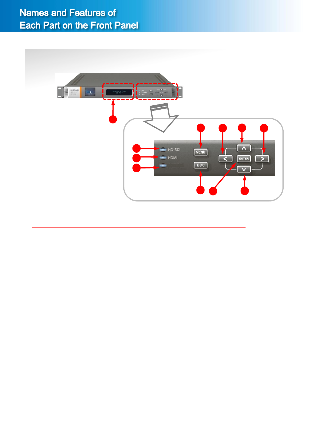
① VFD Display
Displays current status of the device, main menu and 5 different modes of the device function setting
screen.
Press ⑤ MENU button and ⑥ ESC button simultaneously to switch the device setting screen.
② HD-SDI LED
Lights up when the HD/SD-SDI signal of digital mode is normally inputted.
③ HDMI LED
Lights up when the HDMI signal of digital mode is normally inputted
④ IP OUT LED
Lights up when IP OUT signal is normally outputted.
⑤ MENU Button
Used to switch screen to upper menu(previous screen).
⑥ ESC Button
Used to clear selection or cancel manual saving. Also used to move to upper menu.
⑦ ENTER Button
Press when selecting setting and saving manually.
⑧ < Button
Used to move to the left side of the menu.
⑨ ∧ Button
Used to move to the up direction of the menu.
⑩ > Button
Used to move to the right side of the menu.
⑪ ∨ Button
Used to move to the down side of the menu.
7
DME-9724HM
1 2
3
4
5
6 7
8
10
11 9 12 13
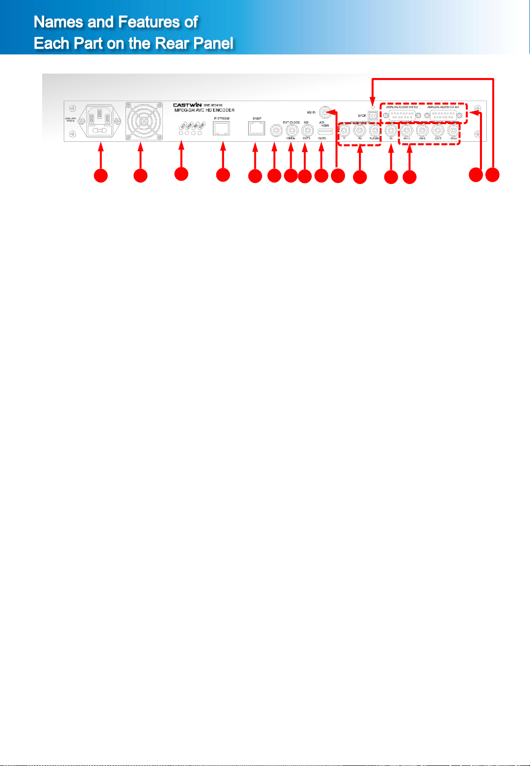
① Power Switch and AC Power Input Terminal
Use power AC 110~220V, 50/60Hz.
② Cooling Fan
③ IP Stream Internet speed LED
ACT LED / LINK LED / Internet SPEED LED for 100M/bps / Internet SPEED LED for 1,000M/bps
④ IP Stream Connection Terminal
A terminal connecting IP stream output. (RJ-45)
⑤ SNMP Connection Terminal
The status of the device can be monitored and controlled in remote area with LAN system using
RJ-45 connection jack.
⑥ EXTERNAL Clock
⑦ ASI 1 signal Output Terminal
TS Signal output terminal of DVB-ASI method.
⑧ ASI 2 signal Output Terminal
TS Signal output terminal of DVB-ASI method.
⑨ HDMI Signal Input Terminal (HDMI Input)
A terminal connecting HDMI signal Input.
⑩ ASI signal Input Terminal (ASI Input)
TS Signal input terminal of DVB-ASI method.
⑪ Component/Composite Signal Input Terminal
A terminal connecting analog video signal input of component method.
⑫ HD-SDI or SD-SDI Signal input Terminal (HD-SDI Input)
A terminal connecting HD-SDI or SD-SDI signal Input.
⑬ 4 channel AES/EBU Digital Audio Signal Input Terminal (ch1, ch2, ch3, ch4)
A terminal connecting digital audio signal input of AES/EBU method. (BNC)
⑭ D-Sub Stereo Analog Audio Signal Input Terminal (ch1/2, ch3/4)
A terminal connecting stereo audio signal input of analog method.
⑮ SPDIF Digital Optical Audio Signal Input Terminal
A terminal connecting digital optical audio signal input of SPDIF method.
14 15
8
DME-9724HM
1-1. Start up
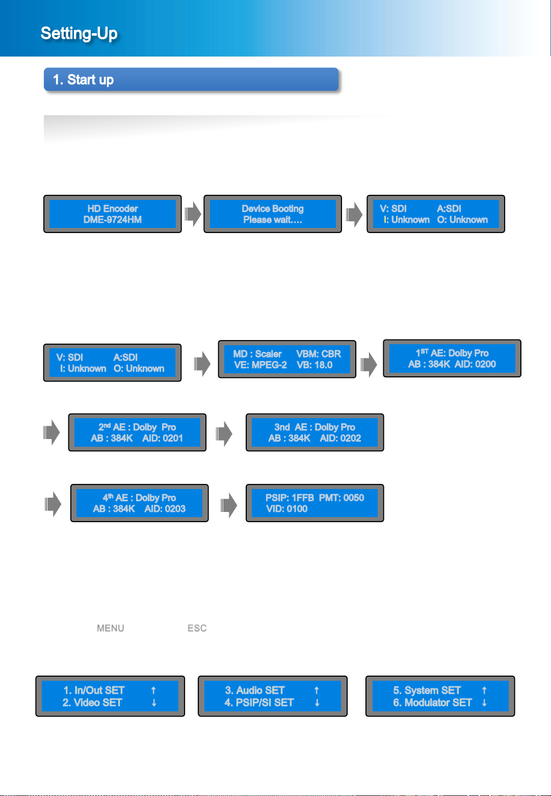
① Connect the AC power to the power input terminal on the back side and turn the power switch ON.
② Booting & Setting
While connecting power, the [Picture 1-1] below will be displayed on the screen and booting of the device
will be accomplished.
[Picture1-1] Setting start up screen
③ Main Screen
When booting is completed, the main screen will be displayed as shown in the [Picture1-2].
In the menu screen of the [Picture 2-1], press ∧ button or ∨ button to confirming the Setting values.
Following information will be displayed on the main screen.
[Picture1-2] Main Screen Pages
④ Setting Menu Screen
When the MENU button and the ESC button is pressed simultaneously in the screen of the [Picture 1-2]
above, a menu screen for device setting will be displayed as shown in the screen of the [Picture 1-3].
[Picture1-3] Menu Screen
9
DME-9724HM
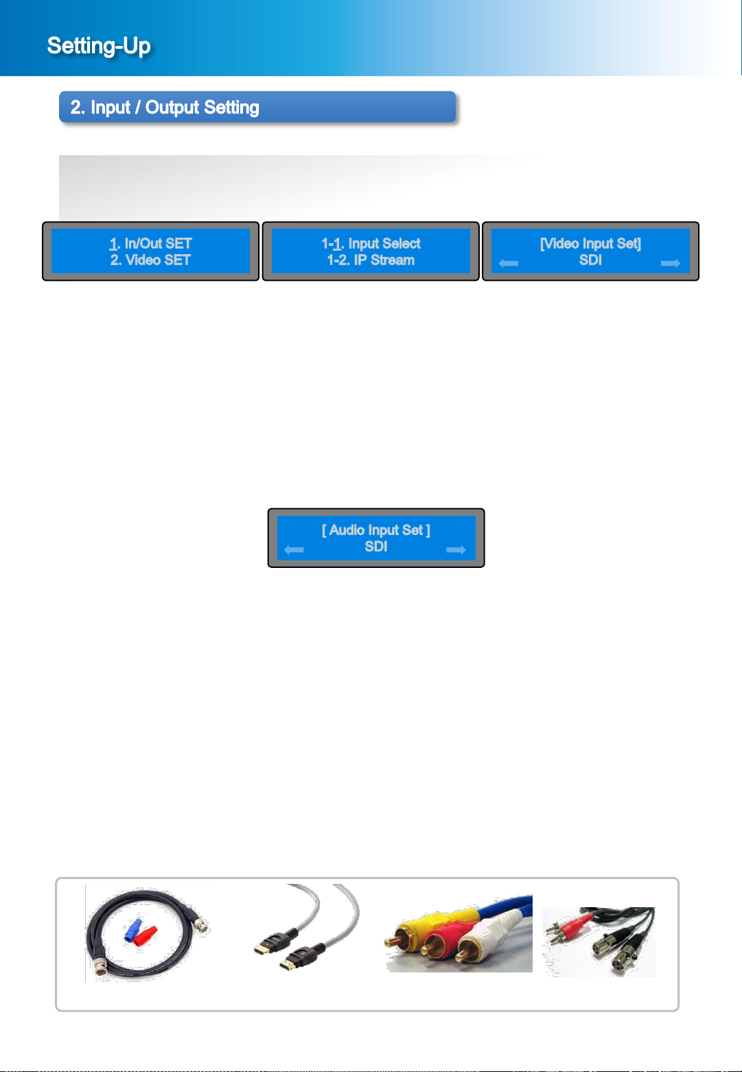
2-1. Setting of Video Input Signal
① When the MENU button and the ESC button is pressed simultaneously in the main screen
[Picture 1-2], a menu screen shown in the [Picture 2-1] will be displayed.
[Picture 2-1] Menu Screen [Picture 2-2] Sub Menu Screen [Picture 2-3] Setting of Video Input Signal
② Setting screen of Video and Audio Input Signal
In the menu screen of the [Picture 2-1], press ∧ button or ∨ button to bring it on “1. In/Out SET” and press
the ENTER button, then the sub menu screen will be displayed as shown in the [Picture 2-2].
In the sub menu screen of the [Picture 2-2], press the ENTER button to bring it on “1-1. Input Select”, then
the setting screen of Video Input Signal will be displayed as shown in the [Picture 2-3].
③ Setting of Video Input Signal
In the screen of the [Picture 2-3], select “SDI” or “HDMI”, “Component”, ”CVBS” using the < button or
>button, then press the ENTER button to save the set value.
④ Setting of Audio Input Signal
In the screen of the [Picture 2-3], select the video input signal and then press the ENTER button to
display the setting screen of Audio Input Signal. Likewise, select “SDI” or “HDMI”, “ANALOG ”,
“SPDIF”, “AES /EBU” using the < button or > button, then press the ENTER button to save the set value.
Press the ESC button to cancel the setting of Video/Audio Input Signal.
Press the MENU button to return to upper menu(previous screen).
This device supports the following three kinds of Video Signal Input.
1. HD-SDI : Digital Signal, 720p/1080i/1080p resolutions
SD-SDI : Digital Signal, 480i/576i resolutions
2.HDMI : Digital Signal 480i/576i/720p/1080i/1080p resolutions
3.COMPONENT : Y/Pb/Pr Signal, 480i/576i/720p/1080i/1080p resolutions
4.COMPOSITE : CVBS Signal, 480i/576i
☞ In case of setting differently from the input signal, the device will not operate normally.
[Picture 2-4] Setting of Audio Input Signal
10
HD/SD-SDI cable Component cable
HDMI cable
Connecting cable for Input Signal
Audio cable
DME-9724HM
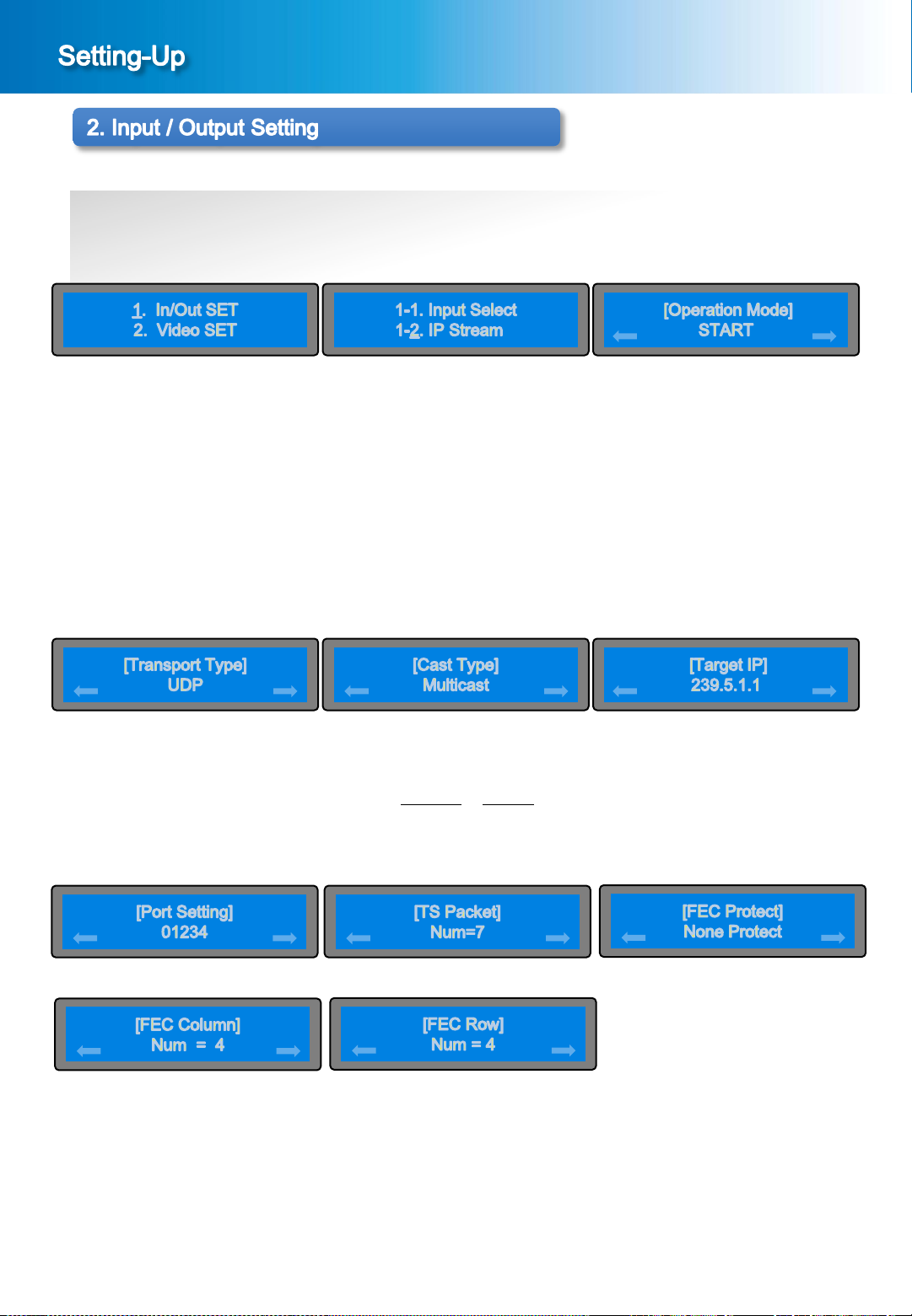
2-2. Setting of IP Stream
① When the MENU button and the ESC button is pressed simultaneously in the main screen
[Picture 1-2], a menu screen will be displayed as shown in the [Picture 2-1].
[Picture 2-1] Menu Screen [Picture 2-5] Sub Menu Screen
② Setting screen of IP Stream
In the menu screen of the [Picture 2-1], press the < button or > button to bring it on “1. In/Out SET” and
press the ENTER button, then the sub menu screen will be displayed as shown in the [Picture 2-5].
In the sub menu screen of the [Picture 2-5], press the ENTER button to bring it on “1-2. IP Stream”, then the
setting screen of IP Stream will be displayed as shown in the [Picture 2-6] START or STOP.
③ Setting of Operation Mode
In the menu screen of the [Picture 2-6], If press the ENTER button in the START status, screen such as
lower part appears in order. If selects the Stop, stops the IP stream.
If select the Start, then press the ENTER button, proceed to [Picture 2-7].
[Picture 2-6] Setting of IP Stream
[Picture 2-8] Setting of Cast Type [Picture 2-7] Setting of Transport Type
④ In the screen of the [Picture 2-7], select the UDP or RTP. If press the ENTER button, proceed to [Picture 2-8].
⑤ In the screen of the [Picture 2-8], select the Multicast or Unicast. If press the ENTER button, proceed to
[Picture 2-9].
⑥ In the screen of the [Picture 2-9], set up the Target IP using the <, >, ∧, ∨ button. If press the ENTER button,
proceed to [Picture 2-10].
[Picture 2-9] Setting of Target IP
[Picture 2-11] Setting of TS Packet [Picture 2-10] Setting of Port Setting
[Picture 2-13] Setting of TS Packet
⑦ In the screen of the [Picture 2-10], can select to 1~65535. If press the ENTER button, proceed to [Picture 2-11].
⑧ In the screen of the [Picture 2-11], can select to 1~7. Press the ENTER button to proceed to [Picture 2-12]
⑨ In the screen of the [Picture 2-12], can select to “None Protect” or “1D Protect”. Press the ENTER button to
proceed to [Picture 2-13]
⑩ In the screen of the [Picture 2-13], can select to 1~31. Press the ENTER button to proceed to [Picture 2-14]
⑪ In the screen of the [Picture 2-14], can select to 1~31. Press the ENTER button to save the setting of IP Stream.
Press the ESC button to cancel the setting of IP Stream.
11
Press the ENTER button to save the setting value.
[Picture 2-14] Setting of FEC Protect
[Picture 2-12] Setting of FEC Protect
3-1. Setting of Video Encoding & Bit Rate
① When the MENU button and the ESC button is pressed simultaneously in the main screen
[Picture 1-2], a menu screen will be displayed as shown in the [Picture 3-1].
DME-9724HM
[Picture 3-1] Menu Screen [Picture 3-2] Sub Menu Screen
[Picture 3-3] Video Encoder
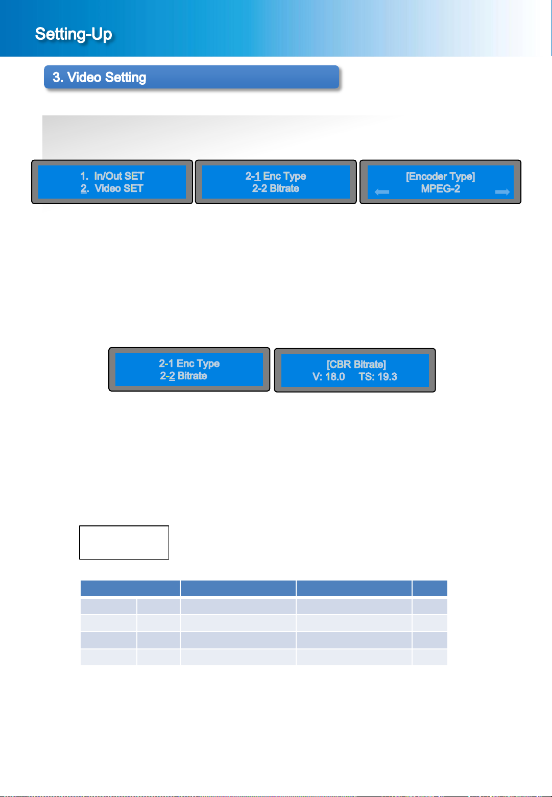
② Setting of Video Encoder
In the menu screen of the [Picture 3-1], press the ∨ button or ∧ button to bring it on “2. Video SET” and
press the ENTER button, then the sub menu screen will be displayed as shown in the [Picture 3-2].
In the sub menu screen of the [Picture 3-2], press the ENTER button to bring it on “2-1. Enc Type”,
then the setting screen of Video Encoding Type will be displayed as shown in the [Picture 3-3] MPEG-2 or
H.264.
[Picture 3-2] Sub Menu Screen
[Picture 3-4] CBR Mode
③ Setting of Video Bit Rate
In the sub menu screen of the [picture 3-2], press the ENTER button to bring it on “2-2”Bitrate”, then the
setting screen of the Video Bitrate Mode will be displayed as shown in the [picture3-4].
In the menu screen of the [Picture 3-4], press the ∨ button or ∧ button to have it indicate desired encoding
bit rate and then press the ENTER button to save the Video Encoding Bit Rate.
Following information will be displayed on the main screen.
V: Video Bitrate
TS: Total Bitrate
Range of the encoding bit rate setting is as below ;
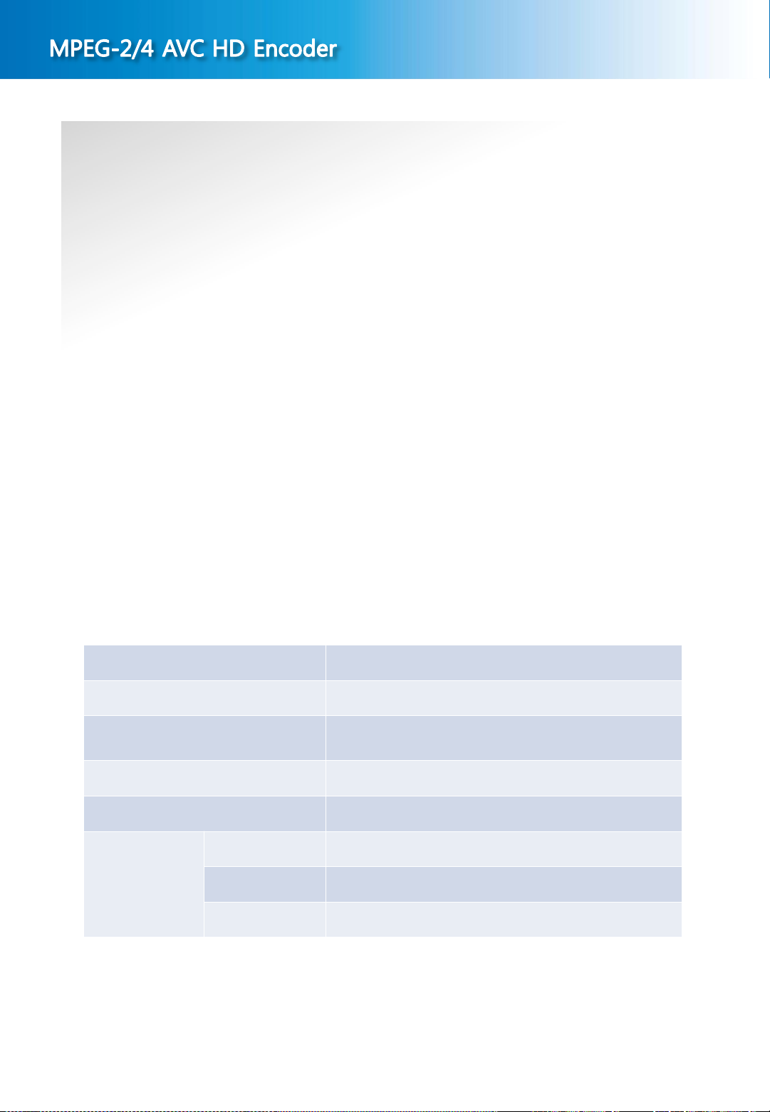
Encoding Type Video Bitrate Total Bitrate Note
H.264 CBR 1.6~50.0Mbps 2.5~52.3Mbps
VBR 1.6~50.0Mbps 2.5~52.3Mbps
MPEG-2 CBR 1.6~50.0Mbps 2.5~52.3Mbps
VBR 1.6~50.0Mbps 2.5~52.3Mbps
▷ Adjustment of the encoding bit rate : Step-by-step adjustment by 0.1 Mbps unit per each step.
□□.□ Mbps
Can increase or decrease the encoding bit rate by 0.1 Mbps unit by pressing the ∧ button or ∨ button.
The set value can be saved by pressing the ENTER button in this state.
Press the ESC button to cancel the set value saved.
Press the MENU button to return to upper menu(previous screen).
12
☞ The video encoding bit rate is set at 18.0Mbps for release.
3-2. Setting of Bitrate Mode
① When the MENU button and the ESC button is pressed simultaneously in the main screen
[Picture 1-2], a menu screen will be displayed as shown in the [Picture 3-1].
DME-9724HM
[Picture 3-1] Menu Screen [Picture 3-5] Sub Menu Screen
[Picture 3-6] CBR Mode
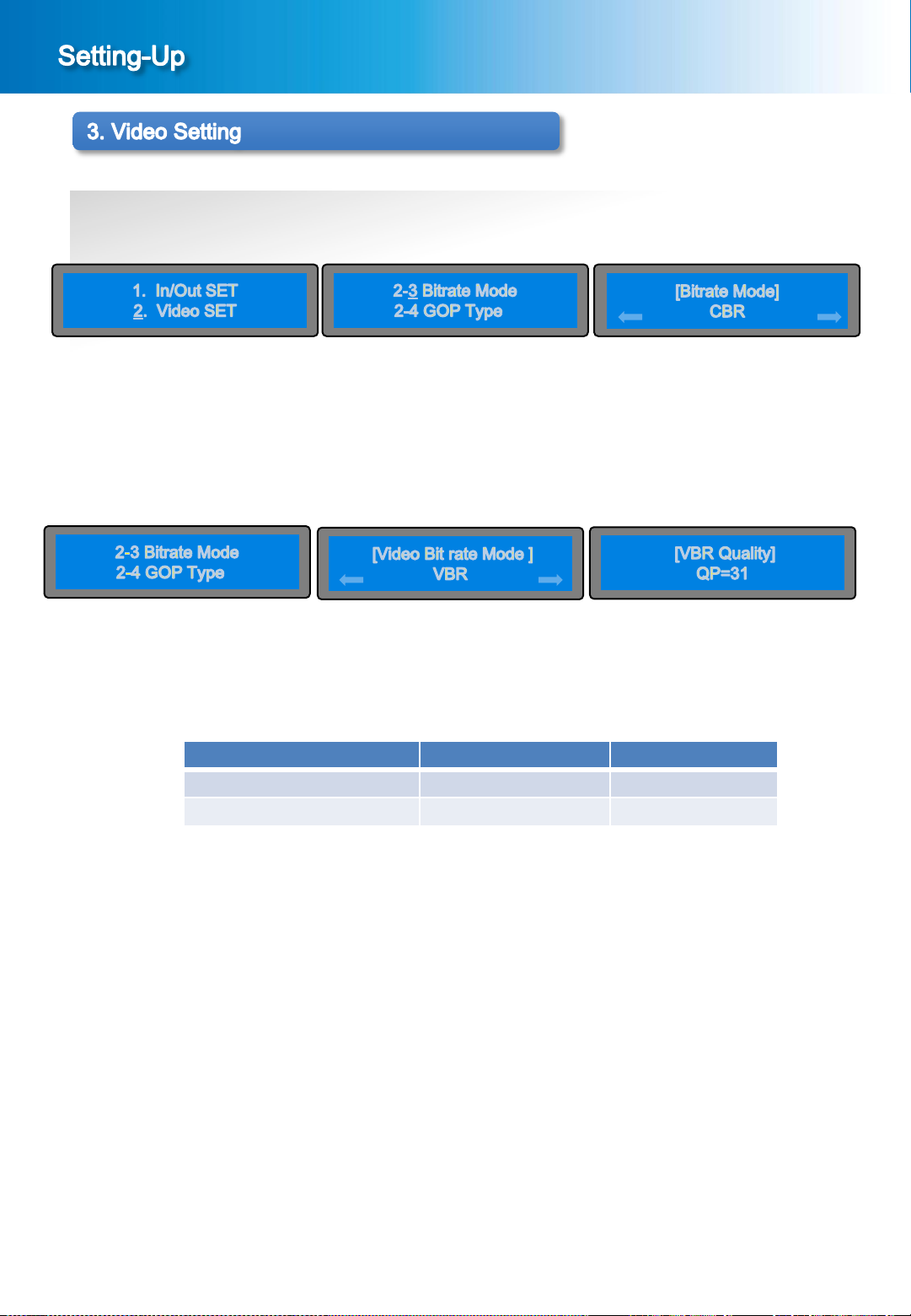
② Setting of Bitrate Mode
In the menu screen of the [Picture 3-1], press the ∨ button or ∧ button to bring it on “2. Video SET” and
press the ENTER button, then the sub menu screen will be displayed as shown in the [Picture 3-5].
In the sub menu screen of the [Picture 3-5], press the ENTER button to bring it on “2-3 Bitrate Mode”,
then the setting screen of Bitrate Mode will be displayed as shown in the [Picture 3-6] VBR or CBR.
[Picture 3-5] Sub Menu Screen
[Picture 3-8] VBR Mode
[Picture3-9] Video Bit Rate
In case of VBR Mode, when you select VBR and press Enter button to bring it on “VBR Quality” as [Picture 3-9].
Range of the VBR Quality setting is as below ;
Encoding Type VBR Quality Point Default Value
H.264 2~51 31
MPEG-2 2~31 10
13
3-3. Setting of Video GOP Type
① When the MENU button and the ESC button is pressed simultaneously in the main screen [Picture 1-2],
the menu screen shown in the [Picture 3-1] will be displayed.
DME-9724HM
[Picture 3-1] Menu Screen [Picture 3-5] Sub Menu Screen
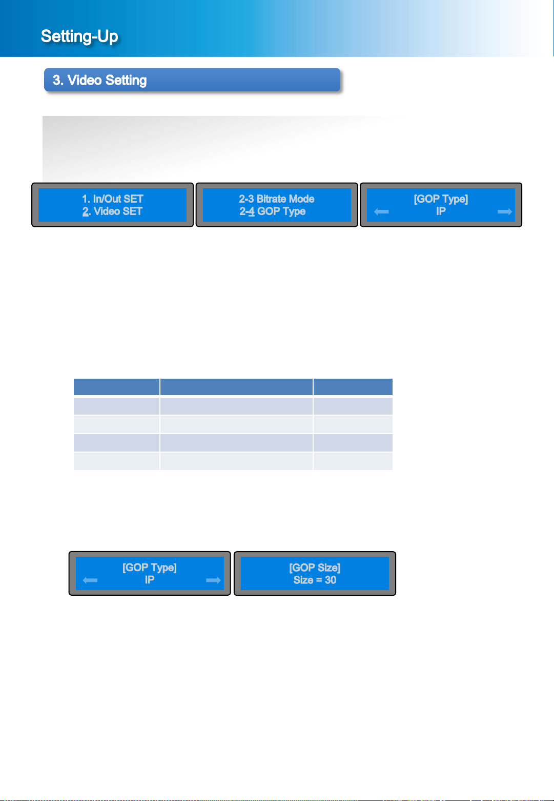
② Setting screen of Video GOP Type
In the menu screen of the [Picture 3-1], press the ∨ button or ∧ button to bring it on “2. Video SET” and press the
ENTER button, then the sub menu screen will be displayed as shown in the [Picture 3-5].
In the sub menu screen of the [Picture 3-6], to bring it on “2-4. Video GOP Type” and press the ENTER button,
then the setting screen of Video GOP Type will be displayed as shown in the [Picture 3-10].
③ Setting of Video GOP Type
According to Latency , the GOP type setting are as below ;
Latency GOP Type NOTE
Max IP/IBP/IBBP
Normal IP
Low IP
Ultra Low P ONLY
In the screen of the [Picture 3-10], set up the IP, IBBP, IBP using the < button or > button, then press the
ENTER button to save the set value.
④ Setting of GOP Size
[Picture 3-10] Setting of Video GOP Type
In the screen of the [Picture 3-10], select the GOP Type then press the Enter button, proceed to [Picture 3-11].
The range of GOP Size is from 2~250.
[Picture 3-11] Setting of GOP Size
[Picture 3-10] Setting of Video GOP Type
14
 Loading...