

Page 1
Integra Fan Flue
Inset Live Fuel Effect Gas Fire
Installation and
Users Instructions
These instructions should be read by the
installer before installation and then should be
handed to the end user when the installation
is complete.
This is an official requirement and is the
responsibility of the fitter of this
appliance.
Having installed the appliance, the installer
should take the necessary steps to ensure
that the user fully understands how to operate
the appliance and is also made aware of the
fire’
s basic cleaning and maintenance
requirements.
Page 2

SECTION PAGE
Notes for the Installer and End User 3
Installation Requirements 4
Installation Procedure 6
Commissioning 10
Operating Sequence 11
Technical Data 11
Replacement Parts 11
Trouble Shooting (GAS SAFE Engineer Only) 12
Control Panel Wiring Diagram 13
Fault Finding Diagram 14
User Instructions 15
Cleaning and Maintenance 16
Fire Front Specifications 16
Coal Layout Instructions 17
Guarantee 19
Trouble Shooting (User) 19
CONTENTS
2
Page 3
THIS APPLIANCE IS INTENDED FOR DECORATIVE PURPOSES
T
his appliance has been designed, tested and manufactured to the European Standard EN509 relating to
D
ecorative Gas Appliances and
m
ustbe installed by a qualified GAS SAFE Registered Installer in accordance
with the Gas Safety (Installation and use) regulations 1994 and all other relevant standards.
This appliance must be connected in accordance with the National Regulations. The appliance must be sealed
i
nto a non-combustible fireplace (Fig. 2) whose only opening must be through a Class I (7” or 175mm diameter)
or Class II (5” or 125mm diameter) chimney / flue of at least three metres in height.
Before installation, ensure that the local conditions, (identification of gas type and pressure) and the adjustment
of the appliance are compatible.
NOTES FOR THE INSTALLER AND END USER
3
An air vent is not normally required for this application because its input does not exceed 7kW. We recommend
that the chimney/flue is swept prior to installation of this appliance and that any flue restrictor or damper plate
should be removed or fixed in the open position. The chimney/flue must always generate a positive up draught to
ensure safe operation.
The installer must then establish that all the products of combustion are entering the flue within five minutes of
lighting from cold.
This can be verified by traversing the canopy with a lighted smoke match (see ‘Spillage Test’
page 5).
An isolation valve must be fitted adjacent to the appliance. When closed, this will allow the complete burner and
control assembly to be disconnected for maintenance or repair in accordance with national regulations.
The gas supply should be provided by a semi rigid pipe with an 8mm diameter and should be no longer than 1.5
metres in length.
Prior to installation, ensure that the local distribution conditions (identification of the type of gas and pressure)
and the adjustment of the appliance are compatible.
NOTE: When the gas supply pipe is passed through masonry or other brickwork always ensure that the end
of the pipe is covered to avoid any debris passing through into the appliance controls.
The appliance is fitted with an Oxygen Depletion Sensor (ODS) that monitors the room for products of
combustion. If products are detected, the ODS will automatically shut down the appliance. If this situation
arises, re-light the appliance, referring to the user instructions (page 14). If shut down re-occurs, a qualified
person must be called to thoroughly check the appliance. The spillage monitoring system (ODS pilot) must
not be put out of operation or be tampered with or adjusted by either the installer or the user. If the unit is
found to be at fault it should be replaced with the manufacturers original replacement parts.
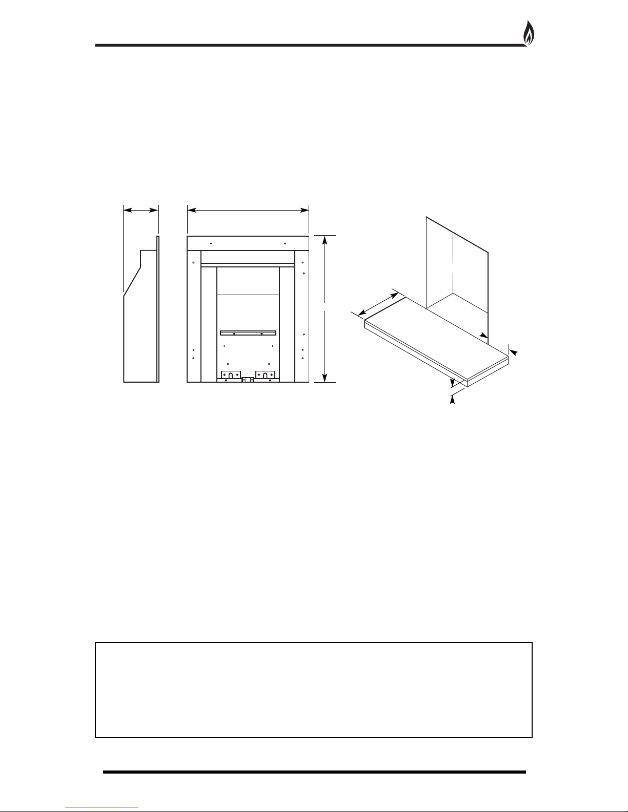
Fireplace Opening
1
50mm (min)
50mm (min)
300mm (min)
Fig. 1
Fig. 2
1
45mm 512mm
608mm
Page 4
This appliance must only be installed in Great Britain or Ireland.
1
. This appliance is a natural gas appliance only and has been designed for use with the following applications:
2. A non-combustible hearth must be provided to comply with current building regulations. Care should be taken
to prevent any damage being caused to surrounding soft furnishings or decoration, e.g. many embossed vinyl
wall coverings may become discoloured if placed too close to the appliance.
3. A suitable proprietary fire surround with 100
0
c rating may be used with a minimum clearance from hearth to
underside of shelf of 830mm, providing that the depth of shelf is 150mm or less.
4. Where the shelf depth is greater than 150mm, the minimum height clearance should be increased by 25mm
i
ncrements for each additional 12.5mm of shelf depth.
5. Minimum width between vertical sides of combustible surround should not be less than 800mm provided the
appliance is central to the surround and the surround legs do not exceed a 150mm profile.
6
. If the 150mm profile is exceeded, the width of the surround (and the back panel) should be increased by
25mm for each additional 12.5mm of profile depth.
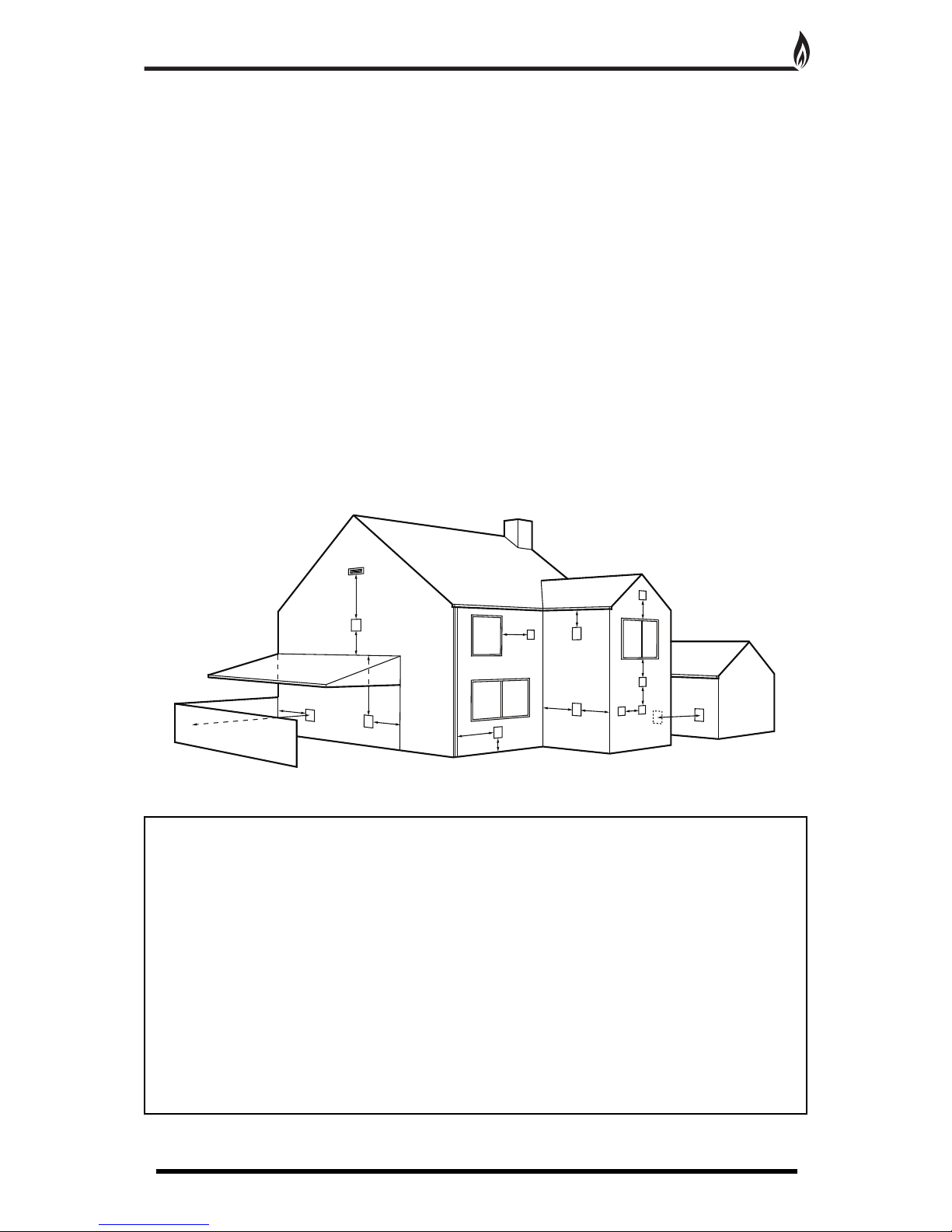
FLUE TERMINAL POSITIONS
The minimum acceptable dimensions from the centre of the flue terminal grille to obstructions and ventilation
opens (Fig. 3).
Dimension Terminal Position Minimum
A
Directly below an opening, air brick, window etc.
300mm
B Directly above an opening, air brick, window etc. 300mm
C Horizontally to an opening, air brick, window etc. 300mm
D
Below gutters, soil pipes or drain pipes
75mm
E Below eaves 200mm
F
Below balconies or car port roof
200mm
G From a vertical drain or soil pipe 150mm
H From an internal or external corner or to a boundary
alongside the terminal 200mm
I
Above ground, roof or balcony level
300mm
J From a surface or boundary facing the terminal 600mm
K From another terminal facing the terminal 1200mm
L
From an opening in a car port 1200mm
M Vertically from another terminal on the same wall 1500mm
N
Horizontally from another terminal on the same wall
300mm
INSTALLATION REQUIREMENTS
4
Fig. 3
A
M
A
N
H
H
K
C
G
H
J
F
L
I
I
DE
B
Page 5

VENTILATION
N
o special ventilation bricks or vents are required in the room containing the appliance, providing that normal
a
dventitious room ventilation exists. The installer must determine this by carrying out a spillage test.
SPILLAGE TEST
To check for satisfactory clearance of products of combustion, close all doors and windows and leave the fire
burning for five minutes. Insert a lit smoke match on a vertical plane 50mm down, 50mm inside the canopy
opening. All the smoke must be drawn into the flue. If spillage occurs, allow a further ten minutes and repeat the
test. Should spillage still occur turn the appliance off and seek expert advice.
T
o continue the test: If an extractor fan is situated in the room the test should be repeated with the fan running. If
there is a connecting room with an extractor fan the test should be repeated with all the doors to that room open
and the extractor fan running.
I
NSTALLATION INTO TIMBER FRAMED DWELLINGS
Where removal of any part of the inner timber leaf of the wall is involved, the structural integrity of the wall must be
maintained and the advice of your local Building Control Department should be sought. If the property is under any
N.H.B.C. cover, it is advised that their advice on this modification should also be sought.
Standard methods of installation may be adapted for use in timber framed buildings, providing extra care is taken to
prevent combustible materials from contact with hot surfaces.
The appliance must be installed in accordance with British Gas documents DM2 and DM3 or the Institute of Gas
Engineers published procedure IGE/UP/7.
Special attention must be paid to the location of the studwork frame of the inner leaf and the appliance positioned
accordingly. Wires and pipes that run within the inner timber leaf must also be located and taken into account when
positioning the appliance.
INSTALLATION USING EXTENDED FIRE SURROUND OR FALSE CHIMNEY BREAST
When using this method of installation the following amendments should be incorporated. 25mm clearance must be
allowed from the appliance firebox to any insulated combustibles. 75mm clearance must be allowed to any
unprotected combustibles.
50mm minimum thickness of insulation should be provided around the flue pipe and gather hood. Where the flue
pipe passes through the inner leaf, a hole 100mm larger than the flue should be cut to allow a 50mm air gap
around the entire flue circumference. The vapour barrier on the back of the inner leaf should be cut and carefully
fixed to prevent any ingress of damp into the plasterboard layer. A layer of insulation will need to be provided to
insulate the surface of the inner wall from the heat ef
fect of the flue. It may be advantageous to use a sheet of
Superlux board for this purpose. When setting the appliance into the inner wall find a suitable position between the
wall panel frames and carefully open up a hole to the dimensions given in the relevant section (section1), paying
careful attention to securing the damp proof membrane back into position. A Drip collar of galvanised or stainless
steel should be formed with the twisted joint on the underside of the flue to disperse drips. An air gap of 75mm
between all hot surfaces and the surrounding wall should be allowed, if protective insulation is used this may be
reduced to 25mm clearance.
The exposed cavity should be sealed off using Superlux or a similar non-combustible board. The board should be
fixed at an angle, lower at the back so as to direct any moisture coming down to the outside wall. This board should
be fixed with screws, Unibond, or a similar adhesive. It is important to fit this board or a cavity tray to protect the
property and the appliance from drips of water.
The sides of the opening where the cavity is exposed should be
packed with Rockwool or similar non-combustible material to a minimum depth of 50mm. The Rockwool packing
must extend from the base of the opening to the Superlux board.
NOTES ON ELECTRICAL INSTALLATION
1. External wiring must be correctly earthed, polarised and in accordance with relevant regulations/rules. In GB this
is the current I.E.E. Wiring Regulations. In IE reference should be made to the current edition of ETCI rules.
2. The method of connection to the electricity supply must facilitate complete electrical isolation of the appliance.
3. Connection may be via a fused double-pole isolator with a contact separation of at least 3mm in all poles.
The appliance must be positioned so that the switch is accessible.
4. If the appliance is to be fitted with a plug, the appliance must be positioned so that the plug is accessible.
5.
THE WIRES FEEDING THE FAN BOX MUST NOT BE ALLOWED TO TOUCH THE REAR OF THE FIRE BOX.
INSTALLATION REQUIREMENTS CONTINUED
5
Page 6

INSTALLATION OF THE FIRE BOX
1. With the fire place fixed on a suitable outside wall, screed the recess to the level of the hearth. This ensures
a
ccurate fitting of the fire and flue spigot alignment with the fan unit.
2.
From Inside: Draw a vertical line centrally on the back wall of the fireplace opening. Measure 407mm up from
the hearth and place a mark on the line. With a suitable drill (approx 10mm) make a hole through to outside
ensuring the drill is kept level.
F
rom Outside: Draw a rectangle 215mm wide x 250mm high centrally above the centre of the drilled hole.
Note: To successfully install this system, the bottom edge of the wall plate must be at least 3” (75mm)
from the outside ground level.
3. Carefully lift the appliance out of the packaging taking care not to damage the ceramic components in the
separate carton.
4. Remove the magnetic trim and store to one side to prevent any damage.
5. Cut the foam sealing strip (in plastic bag supplied) to length and stick a continuous strip down the two sides
and across the top of the radiant box. When the box is placed against a flat surface the foam strip will form a
seal around the boxes flange.
6. Insulate the rear of the fire box with Rockwool or similar.
7. Carefully lift the appliance into position in the fireplace opening and check that the flange of the radiant box
fits flush against the sealing face with no gaps present.
8. Remove the four screws that secure the burner tray to the box, two on the front leg and two at the rear of the
tray. Remove the burner tray and place to one side (Fig. 5).
INSTALLATION PROCEDURE FOR STANDARD 22” X 16” OPENING
6
Fig. 5
Blanking plate
Foam Sealing Strip
Magnetic Trim
Burner tray
Fig. 4
H
ole (10mm approx.)
Hole (10mm approx.)
Hearth Level
H
earth
O
utside Inside
2
15mm
250mm
407mm
Page 7

INSTALLATION PROCEDURE FOR STANDARD 22” X 16” OPENING CONTINUED
7
9. With the radiant box placed in the opening, mark out four of the eight fixing holes. Remove the box and
c
arefully drill and fit rawl plugs.
10. Temporarily fix the flue spigot to the rear of
the radiant box with the the four self tapping
s
crews provided. Offer the radiant box with the
s
pigot attached into the fireplace opening.
(carefully tuck or clip the cables over to the left
hand side of the opening, ensuring that they do
not come into contact with the fire box). The
s
pigot should protrude through the outer hole in
the brickwork. Screw the radiant box to the back
panel.
1
1. Take off the outer fan box cover by removing
t
he single screw near the flue outlet and swinging
the cover upwards to disengage on the mounting
rail. To remove the fan unit, unscrew and remove
t
he lower two screws and partially unscrew the
top screws. The unit can now be lifted off the two
rear screws via the keyhole slots.
12. From the outside, position the fan box into the cut out of the brickwork and over the protruding spigot
ensuring that the fan box flanges are flat against the brickwork. Mark the flue spigot so that it would be just
below ‘flush’ with the face of the fan box (on final fix the spigot should not touch any part of the fan unit as this
can cause a vibration noise). Remove the radiant box and cut the spigot to length.
12. Having cut the spigot to length, the radiant box should be of
fered up to the fireplace opening for the final fix.
Before fixing, the power cable should be fed round the back of the fireplace to a wall mounted power source.
This can be a three pin plug fused 3amp or by a fixed connection to a 3amp, all pole switched fused spur. The
spur must have a contact separation of at least 3mm. The ten core cable with the two six way connector plugs
should be temporarily fed through the flue spigot. The radiant box can now be screwed securely to the back
panel.
INSTALLING THE FAN UNIT
W
arning - This
Appliance MUST Be Earthed
1. Take the wall plate and place into the outside hole and over the cut to length spigot making sure that the inner
and outer spigots line up with each other centrally.
Make sure that the cable entry hole is in the top right hand corner (as the fan will only fit one way round)
Fig. 6
Fig. 7
Fixing
H
oles
F
ixing
H
oles
F
ixing Holes
Face of Wall Plate
Flue Spigot
Cut Line
Page 8

INSTALLATION PROCEDURE FOR STANDARD 22” X 16” OPENING CONTINUED
8
2. Working from inside the fan box, remove the cable retaining plate by unscrewing the two screws in the upper
lefthand corner. Feed the ten core wire through the rectangular cable hole. Secure the cable glands to the
retaining plate, leaving approximately 6” of cable from the connectors to the plate. Secure the retaining plate into
position using the two screws.
3. Slide the fan box into the wall. Making sure the outer cowl of the fan box is touching the wall all round, secure
the fan box into position using the four clamping bolts. Adjust the bolts so that the fan box sits centrally with the
flue. If the bolts cannot clamp to the brick (due to the design of brick) use the two packing pieces provided.
Use the silicone provided to seal the top and side edges of the fan box cowl to the wall.
4. Feed the glass fibre rope gently into the gap between the inner and outer spigot to form a ring seal between
them. The rope can be pushed into the gap with a large flat bladed screwdriver. Care must be taken not to push
the rope too far, as it may fall into the cavity. It only needs to be inserted enough to form a seal between the
mating spigots.
5. Replace the fan unit by hooking the keyhole slots over the heads of the top mounting screws. Replace the two
lower screws and tighten the upper two.
6. Connect the two six way plugs from the PCB and fan wiring loom to the plugs on the ten core wire.
7. Replace the cover panel by engaging it’s top channel into the mounting rail in the fan box. Swing the cover
downwards and secure with the retaining screw (Fig. 8).
PLEASE NOTE: Silicone sealant should be used to seal round the top and two sides of the Fan Box
Cowl only
.
NOTE: The fitter will be held responsible and will be liable to fund the replacement
if the unit is not sealed correctly
.
Fig. 9
Inner spigot
Fan Box Cowl
Glass fibre rope
F
ig. 8
S
pigot
C
able entry hole
F
an Box Cowl
F
an unit
Outer cover
O
uter cover
F
an Box Cowl
Connectors
Cable Glands
Retaining Plate
6”
Page 9

INSTALLATION PROCEDURE FOR STANDARD 22” X 16” OPENING CONTINUED
9
8
. Position the burner tray into the box in order to determine the length of 8mm gas supply needed and cut to
length.
9. Before making the final connection, thoroughly purge the supply pipe to clear any foreign matter, i.e. masonry
d
ust etc, as this could lead to blockages in the control valve and/or pilot assemblies.
10. Fix the burner in place using the four screws and make the gas connection.
A
LTERNATIVE FIXING METHOD
Where the drilling of the back panel is not practical, an alternative fixing method may be employed using the
cable fixing kit provided. Drill four holes in the rear of the fireplace opening (Fig. 11). Securely fix the four eye
b
olts provided using suitable rawl plugs. Feed one cable through each of the top holes in the rear of the
fire box.
Fix the radiant box into the opening, securing into position using the cable fixing kit (Fig. 10). Do not cut off the
loose ends as the full length is required should the radiant box need refitting at any time. Coil up and securely
store underneath the burner tray.
C
entre Line
Drill Holes for 4 eye bolts
on 112mm centre lines
between max and min height.
65mm
min
11
5mm
max
5
00mm
min
5
50mm
max
112mm
1
12mm
Fig. 11
Radiant box
Outer fan cover
Hearth
Eye Bolts
Tension Nut
Cable Clamping Screw
Fig. 10
Page 10

INSTALLATION PROCEDURE FOR DECORATIVE CAST SURROUND
10
1. Install the decorative cast surround into the fireplace opening and ensure it is fully sealed including the open
area above the fire (see Fig. 12).
2
. Carefully lift the fire box out of the packaging taking care not to damage the ceramic components in the
separate carton.
3. Cut the foam sealing strip (in plastic bag supplied) to length and stick a continuous strip up one side, across
t
he top and down the other side of the rear of the radiant box. When the box is placed against the cast surround
the foam strip will form a seal around the boxes flange.
4. Lift the fire box on to the two studs at the top of the surround and
check that the flange of the radiant box fits flush against the sealing
f
ace with no gaps present.
5. Locate the decorative frame on to the studs and secure with the
two nuts provided.
6. Insert the two screws into the lower holes in the decorative frame
and carefully tighten ensuring the fire box is securely clamped
between the frame and the surround.
Fig. 12
Decorative Cast
Surround
S
ecuring
Studs
Securing Screws
Decorative Frame
ENSURE THIS AREA
I
S SEALED
Foam Sealing Strip
1. Carry out a gas soundness test.
2. Unscrew the pressure test point sealing screw (Fig. 13) and fit a manometer
.
Consult the user instructions (page 15). Ignite the appliance and turn to the high
position.
3. Take a pressure reading and consult the technical data (page 11) to establish the correct working pressure.
4. Once the pressure has been checked and verified, turn off the appliance. Consult the ceramic component set
up diagrams (page 17 - 18) and fit the ceramics as per the instructions.
5. Carry out a Spillage
T
est (see page 5).
Fig. 13
Pressure Test Point
COMMISSIONING
Page 11

Gas Type Natural Gas (G20) Cat I
2H
Gas Connection 8mm
Number of Injectors One
Injector Size Stereomatic 068
Control Max Operating Temperature 80
o
c
Inlet Pressure Cold 20 mbar (8” W.G.)
Heat Input (Gross) 6.2 kW
Weight 11.4kg
230V ac 50Hz 55W Fuse Rating 3A IPX4D
1.
Loose coals - The ceramic coals supplied with this appliance can be replaced at service intervals depending
on their condition. If the coals do require replacement, the consumer can do so provided that the Ceramic
Component Layout Instructions (pages 17 - 18) are adhered to. Under no circumstances should additional/extra
coals be added. Only genuine Legend replacement parts should be used.
Order Ref:
SLC05
2. Front Coal, Fuel Bed and Side Cheeks - All these ceramic components can be replaced at service intervals
depending on their condition. If the coals do require replacement, the consumer can do so provided that the
Ceramic Component Layout Instructions (pages 17 - 18) are adhered to. Only genuine Legend replacement
parts should be used.
Order Ref:
SFC02, SCM03, SSC04,
3. Oxygen Depletion Sensing Pilot - In the unlikely event of a pilot failure, the pilot assembly should only be
replaced by a
GAS SAFE Registered Engineer. The user must not carry out this work.
Order Ref:
LEG01
4. Control Tap- In the unlikely event of control tap failure, the assembly should only be replaced by a
GAS SAFE Registered Engineer.
The user must not carry out this work.
Order Ref:
LEG02
5. If the supply cord is damaged, it must be replaced by a new harness assembly from the manufacturer or
service agent. Order Ref:
LEG35
6. Fan Unit Spares:
a. Pectron Board - Order Ref: LEG33
b. Solenoid V
alve
- Order Ref: LEG18
c. Fan Blower - Order Ref: LEG36
d. Pressure Switch - Order Ref: LEG34
OPERATING SEQUENCE
1
1
REPLACEMENT PARTS
TECHNICAL DATA
This system is basically an add on to an existing manual fire. The fan proving unit operates in such a way that
when the fan is running and all the safety features are checked OK, then it opens a solenoid up stream of the
g
as valve to allow gas to the manually operated gas valve.
Sequence: Initially with the unit in it’s off state, the gas valve relay contacts are open circuit and the fan is off.
To activate the unit, the user depresses the ON switch, at this point the APS is checked. If this indicates that fan
p
ressure is already present, no further action will occur and when the user releases the ON switch, the unit will
be in it’s off state.
If the APS indicates no airflow, then the fan will be switched on at it’s high rate. Once the unit is in this state, it
w
ill then wait until the APS ON contacts are made.
Once air pressure has been established, the fan will be switched to it’s service speed. After a delay, the gas
valve relay will be activated allowing a current to energise the solenoid valve so that gas can flow to the
m
anually operated gas valve. At this point a green neon will be illuminated.
Manual ignition can now take place.
If during running, the APS signals air flow failure, then the unit will switch back to high speed. If the ON contact
is not made in the APS, then the unit will switch off after a period of 6 seconds. In it’s off state, the gas valve
relay contacts are opened and the gas solenoid is closed. The fan is switched off and the neon will be
extinguished. Ignition will not be started unless the fan is switched back on manually.
At any time the user can press the off switch, this will cause the fan to shut down in the same manner as
described above.
Page 12

TROUBLE SHOOTING (GAS SAFE ENGINEER ONLY)
12
1. The Piezo will not spark.
Check: If the electrode is cracked or broken - Replace pilot assembly.
I
f the HT lead is shorting out on the burner body - Locate where the short is occurring, isolate
and/or re-route the lead.
If the HT unit/lead is faulty - Replace as necessary.
2
.
T
he Pilot will not light (but the Piezo is sparking).
C
heck: If the gas is reaching the pilot - check joints and connections.
If the pilot jet is blocked - Inspect and clean.
If the pilot is still not passing gas - Replace the pilot assembly.
3
.
T
he Pilot lights but goes out when the control knob is released.
Check: If the Thermocouple is loose/disconnected at the control valve - remake the connection.
If the Thermocouple is faulty - Replace.
If the Electro magnetic valve is faulty - replace valve.
4
.
T
he Burner will not light readily from the pilot.
Check: If the coals are obstructing the pilot to burner path ie. Are the coals blocking the opportunity for
the pilot to light the burner - Relay the coal set as per Ceramic Component Layout Instructions.
(pages 17 - 18).
5.
The fire makes a roaring noise when lit.
Check: That the front coal is seated correctly and the pilot hole is positioned correctly over the pilot
assembly.
IF ANY PART OF THE PILOT ASSEMBLY IS SUSPECTED AS BEING FAULTY THE COMPONENT MUST BE REPLACED.
6. The flames appear blue (after the fire has fully warmed up). The coals/ceramic liners have soot
deposits.
Check: That the coals have not moved from the original setting - Relay the coals as per the Ceramic
Component Layout Instructions (pages 17 - 18).
There may be too little/much ventilation into the room. Identify and then take steps to rectify.
7.
The flame picture is low on the high setting.
Check: For any partial blockages - Check all obvious locations for debris in pipe work and fittings.
Inlet gas pressure, both standing and working gas pressure - Identify problem and take
necessary steps to rectify.
Note: Flame pattern improves with use.
8.
Fumes enter the room when the fire is operating.
Check: Why the chimney is not drawing all the products of combustion up the flue, identify where the
problem lies and rectify, otherwise disconnect the fire and seek professional guidance.
Fig. 14
Page 13

CONTROL PANEL WIRING DIAGRAM
13
b Blue
lb Light Blue
l Lilac
o Orange
y Yellow
g Grey
br Brown
bk Black
r Red
w White
g/y Green\Yellow
p Purple
Fig. 15
Page 14

FAULT FINDING DIAGRAM
14
Page 15

15
USER INSTRUCTIONS
L
ighting Procedure
1. To light the fire, remove the ash pan cover.
2. To switch on the appliance, first turn the mains electricity supply on at
the fused spur or switched plug. Switch on the fan by keeping the ON
switch pressed until the green neon GAS ON indicator illuminates.
Gas is now available at the burner.
3. Control knob to be in POSITION 1 at commencement of the
ignition sequence.
4. Fully depress control knob and turn anticlockwise to POSITION 2
where it reaches a natural restriction (allow a couple of seconds for the
pilot gas to purge through the pipe). A sparking click is heard/felt and the pilot
flame is then lit. The pilot assembly is located at the front lefthand side of the fire, and when ignited (this can
take two or three ‘clicks’) it can be seen through the front coal set. Keep the knob depressed for 10/15 seconds
to allow the thermocouple to establish the pilot flame. The knob can then be released.
5. The operating level of the burner is now set by turning the control knob from the pilot
POSITION 2
through the
maximum setting POSITION 3 to the minimum POSITION 4. The control knob is adjustable between these two
positions.
6. To turn off the appliance, depress the control knob and turn clockwise until the POSITION 2 is reached. The
main burner will go out but the pilot light will still be lit.
The pilot can then be extinguished by depressing the
control knob and then turning to the off
POSITION 1.
T
o turn of
f the fan simply press the F
AN OFF switch.
WARNINGS:
Never throw rubbish on, or otherwise disturb the fuel bed.
Any alteration to this appliance including its ceramic components may render it inoperable and
unsafe.
THIS APPLIANCE IS INTENDED FOR DECORATIVE PURPOSES.
P
lease also familiarise yourself with the Notes for the Installer and End User on page 4.
OPERATION AND CONTROLS
I
t is most important that the operator of this gas appliance has fully read and understood all the operating,
cleaning and maintenance procedures as laid out in these instructions.
P
OSITION 1
O
FF
P
OSITION 2
IGNITION/PILOT
POSITION 3
M
AXIMUM SETTING
P
OSITION 4
MINIMUM SETTING
Fig. 16
Fig. 17
OFFON
G
reen neon indicator
On/off switches
Page 16

Cast Tec Fires recommend that this appliance is serviced at regular 12 monthly intervals. The chimney
or flue should also be checked regularly to ensure that all products of combustion are entering the flue
a
nd there is no excessive build up of soot.
I
t is the users responsibility to ensure that the appliance is kept in a clean serviceable condition.
1. Ceramic Components and Fuel Bed - Debris from any
source should be removed with a soft brush. Please ensure
t
hat any debris including soot deposits are removed from the
appliance and not left on the fuel bed. It is recommended that
the user should, on a regular quarterly basis, carefully
remove all ceramic components and thoroughly clean the
stainless steel burner strip and the pilot assembly. Any build
u
p of debris in this area could affect the operation of the
appliance.
NOTE: It is common to find surface cracks in the ceramic components. This is due to the expansion and
contraction of the ceramic fibres caused by the intense heat that the burner generates. The cracks will not
affect the safe operation of this appliance. However great care must be taken when handling the ceramic
components as they will break if handled incorrectly. Do not use a vacuum cleaner to clean the ceramics.
2.
Radiant Box Ceramic Liners - Use only a soft brush to remove any soot deposits from the ceramic liners
during cleaning as this is the only method that can be used to remove deposits. The ceramic liners are very
delicate and should be treated accordingly.
3.
Brass Trims and Frets - The brass trim and fret should be removed from the appliance for cleaning, please
ensure that the appliance has cooled thoroughly. Polished metal trims and frets are not lacquer coated and
therefore require polishing. It is recommended that a good quality metal polish is used.
4.
Fan - Remove any household fibres or soot build-up from the blades of the fan with a suitable brush.
FIRE FRONT SPECIFICATIONS
Fire fronts are now available in many different designs and finishes. The user can now choose their own
particular style of fire front to suit their individual fireplace setting, providing the fire front complies with the
following dimensions -
Fire Front - (X) Max: 210mm Min: 190mm
Ash Pan Cover - (W) Max: 90mm Min: 65mm
(Y) Max: 345mm Min: 320mm
SAFETY
W
ARNING
- This appliance has a naked flame and as with all heating appliances a fireguard
should be used for the protection of children, the elderly and infirm. Fireguards should conform to
BS 6539 (1984 Fireguards for use with solid fuel appliances). This fire is not fitted with an integral
guard. In normal use consideration may be given to the use of a fireguard confirming to BS 6539,
such that the approach to the naked flame is minimised.
CLEANING AND MAINTENANCE
16
w
Y
X
Minimum area free space 15cm
2
Minimum area free space 5cm
2
Fig. 19
Stainless Steel Burner Strip
P
ilot Assembly
Fig. 18
Page 17

COAL LAYOUT INSTRUCTIONS
17
1. Place the main fuel bed on to the middle section of
the metal burner tray. It is important that the front edge
of the fuel bed is located behind the burner strip
(Fig. 21).
2. Position the front coal on the front coal retainer,
making sure that the back edge is pushed up against
the front of the burner strip (Fig. 22).
3. Place the side cheeks into position, making sure
they are positioned either side of the fuel bed and the
overhang is at the front.
The outside edge should be in
contact with the radiant box ceramic liner
. Ensure that
the lower part of the side cheeks sit on the front coal
(Fig. 23).
It is very important that all the coals are used and
arranged as shown in order to achieve the desired
flame picture.
It may be necessary to remove some or all of the coals
to clean them at some time. Cleaning must only be
d
one using a soft brush.
C
AUTION: The coals are extremely fragile and must
be handled accordingly. Gloves should be worn and
a
ny inhalation of dust should be avoided. The coals
must be kept away from children at all times. Never
p
ut additional coals on the fire. Never use coals
other than those originally supplied, or genuine
L
egend Spare Parts.
Fig. 20
Fig. 21
Fig. 22
Fig. 23
Burner Tray
B
urner Strip
Right Hand
Side Cheek
Left Hand
Side Cheek
F
uel Bed
Front Coal
Page 18

COAL LAYOUT INSTRUCTIONS CONTINUED
18
5. Pick out the smallest two coals and lay to one side,
lay the first row of four loose coals on top of the front
coal. Ensure the back of the coals are resting on the
coal bed and there are even gaps all round (Fig. 24).
6. Choose three loose coals and place them in line on
the next row up, again making sure all the gaps are
even. It is important that the coals ‘bridge’ the peaks of
the fuel bed and are not placed in between. This helps
the flow of burnt gases and should give an even
glowing fuel bed (Fig. 25).
8. Place the next two coals in the middle, on the back
edge of the coals previously laid ensuring even gaps all
round. Finally place the two small coals, one in each
top corner. Make any adjustments necessary to achieve
even gaps as this will help in giving a well balanced
flame picture and an even glow (Fig. 26).
F
ig. 24
Fig. 25
Fig. 26
Small Coal
Small Coal
Page 19

GUARANTEE
19
Your appliance is guaranteed for one year from proof of purchase. Should the appliance prove defective within
t
hat period we agree to repair or replace (at our discretion) the component or appliance provided that:
1. The user can produce a receipt for proof of purchase/installation.
2
. The appliance has been supplied by an authorised stockist and has been installed by a qualified installer, all
installation and operating instructions have been strictly adhered to.
3. No alterations have been carried out on the appliance or component parts without our written consent.
4
. The appliance has not been used for any purpose other than those intended.
5. The appliance has not been damaged accidentally or due to fair wear and tear.
Guarantee claims should be made through your appliance supplier. The Guarantee is restricted to UK Mainland
a
nd is additional to your statutory rights.
TROUBLE SHOOTING (USER)
1. The Fire will not light.
Remove the brass fret and check the pilot area for soot.
If soot is present remove all the loose coals and the front coal and thoroughly clean any debris
in and around the pilot area.
If the fire will still not light contact your installer.
2.
The flames appear blue - excessive soot deposits.
The ceramic components including the coal need relaying (pages 17-18).
Too much or too little room ventilation. Seek professional advice.
3.
Roaring noise coming from the pilot.
The front coal is not seated correctly. Turn the appliance off and allow to cool down. Re-seat
front coal, ensuring it is flat to the base of the front coal retainer (page 17).
4.
All the Ceramic Components are discolouring.
The ceramic sets and liners are all manufactured from ceramic fibre and its natural colour is
white, dyes are used to give it a realistic appearance. These dyes discolour after they have
been subjected to intense heat. However the discolouration does not af
fect the operation of the
appliance. The realistic appearance can be restored with the use of a good replacement dye
that can be purchased from most good fireplace showrooms.
Page 20

Unit 200
Glenfield Park Site 1
Philips Road
Blackburn
Lancashire
BB1 5PF
Tel: 01254 695244
Fax: 01254 695255
W
eb:
www
.legend-fires.com
Email: info@legend-fires.com
Issue B - 17/6/11
 Loading...