

Page 1
Integra Convector Plus Manual
Inset Live Fuel Effect Gas Fire
Installation and
Users Instructions
These instructions should be read by the
installer before installation and then should be
handed to the end user when the installation
is complete.
This is an official requirement and is the
responsibility of the fitter of this
appliance.
Having installed the appliance, the installer
should take the necessary steps to ensure
that the user fully understands how to operate
the appliance and is also made aware of the
fire’s basic cleaning and maintenance
requirements.
Page 2

Page 3

SECTION PAGE
Notes for the Installer and End User 4
Installation Requirements 5
Installation Procedure - Standard 22” x 16” 6
Installation Procedure - Decorative Cast 8
Commissioning 8
Removing the Baffles 9
Technical Data 9
Replacement Parts 9
Trouble Shooting (GAS SAFE Engineer Only) 10
User Instructions 11
Cleaning and Maintenance 12
Fire Front Specifications 12
Coal Layout Instructions 13
Guarantee 15
Trouble Shooting (User) 15
CONTENTS
3
Page 4
THIS APPLIANCE IS INTENDED FOR DECORATIVE PURPOSES
T
his appliance has been designed, tested and manufactured to BS7977-1:2009 relating to Decorative Gas
A
ppliances and
m
ustbe installed by a qualified GAS SAFE Registered Installer in accordance with the Gas
Safety (Installation and use) regulations 1994 and all other relevant standards.
This appliance must be connected in accordance with the National Regulations. The appliance must be sealed
i
nto a non-combustible fireplace (Fig. 2) whose only opening must be through a Class I (7” or 175mm diameter)
or Class II (5” or 125mm diameter) chimney / flue of at least three metres in height.
Before installation, ensure that the local conditions, (identification of gas type and pressure) and the adjustment
of the appliance are compatible.
NOTES FOR THE INSTALLER AND END USER
4
This fire is a very effective heating appliance and must be fitted against a wall of non-combustible material as
classified in BS 476-4:1970 (2007).
An air vent is not normally required for this application because its input does not exceed 7kW. We recommend
that the chimney/flue is swept prior to installation of this appliance and that any flue restrictor or damper plate
should be removed or fixed in the open position. The chimney/flue must always generate a positive up draught to
ensure safe operation.
The installer must then establish that all the products of combustion are entering the flue within five minutes of
lighting from cold. This can be verified by traversing the canopy with a lighted smoke match (see ‘Spillage Test’
page 5).
An isolation valve must be fitted adjacent to the appliance. When closed, this will allow the complete burner and
control assembly to be disconnected for maintenance or repair in accordance with national regulations.
The gas supply should be provided by a semi rigid pipe with an 8mm diameter and should be no longer than 1.5
metres in length.
NOTE: When the gas supply pipe is passed through masonry or other brickwork always ensure that the end
of the pipe is covered to avoid any debris passing through into the appliance controls.
The appliance is fitted with an Oxygen Depletion Sensor (ODS) that monitors the room for products of
combustion. If products are detected, the ODS will automatically shut down the appliance. If this situation
arises, re-light the appliance, referring to the user instructions (page 1
1). If shut down re-occurs, a qualified
person must be called to thoroughly check the appliance. The spillage monitoring system (ODS pilot) must
not be put out of operation or be tampered with or adjusted by either the installer or the user. If the unit is
found to be at fault it should be replaced with the manufacturers original replacement parts.
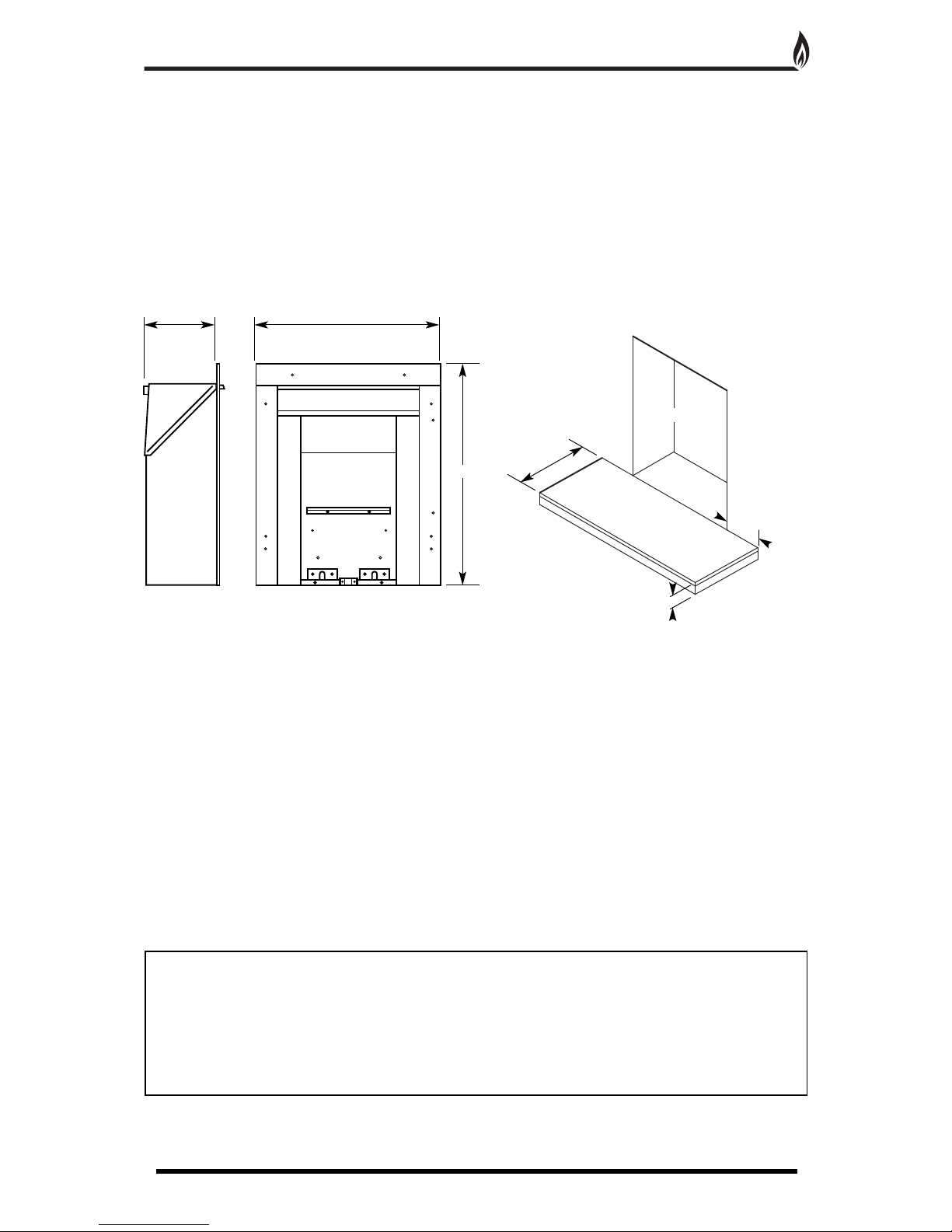
Fireplace Opening
1
50mm (min)
50mm (min)
3
00mm (min)
Fig. 1
Fig. 2
195mm 512mm
612mm
Page 5

This appliance must only be installed in Great Britain or Ireland.
1
. This fire is a natural gas appliance and has been designed for use with the following applications:
a)
Class I - Conventional brick or stone chimney as used for a solid fuel fire with a cross sectional dimension of
2
25mm x 225mm (9” x 9”) or a lined flue with a minimum diameter of 175mm (7”), with the fireplace components
conforming to BS1251, or a builders opening a minimum of 560mm high and 406mm wide with a minimum depth
of 230mm to allow sufficient volume for debris collection. To obtain this depth it would not normally be necessary
to remove the chair brick. Any permanent flue restrictions or variable dampers are to be removed or locked in the
fully open position. The chimney should also be swept prior to installation.
b)
Class II - A double walled or insulated metal flue box built to the requirements of BS715 with an insulated flue
having a minimum diameter of 125mm (5”) and a minimum effective overall height of 3 metres (10’).
NOTE: If the flue box is to be used with an existing brick or stone chimney, a 125mm (5”) minimum diameter
f
lue liner conforming to BS715 may be used.
2. A non-combustible hearth must be provided to comply with current building regulations. Care should be taken
to prevent any damage being caused to surrounding soft furnishings or decoration, e.g. many embossed vinyl
wall coverings may become discoloured if placed too close to the appliance.
3. A suitable proprietary fire surround with 100
0
c rating may be used with a minimum clearance from hearth to
underside of shelf of 830mm, providing that the depth of shelf is 150mm or less.
4. Where the shelf depth is greater than 150mm, the minimum height clearance should be increased by 25mm
increments for each additional 12.5mm of shelf depth.
5. Minimum width between vertical sides of combustible surround should not be less than 800mm provided the
appliance is central to the surround and the surround legs do not exceed a 150mm profile.
6. If the 150mm profile is exceeded, the width of the surround (and the back panel) should be increased by
25mm for each additional 12.5mm of profile depth.
FLUE FLOW TEST
A flue flow test (smoke test) is carried out to check the effectiveness of the flue and to ensure that there is no
leakage into another part of the premises (including any loft), or as appropriate other adjoining premises (this is
particularly important where a number of chimneys combine into a multiple stack).
The flue flow test should be carried out using a suitable smoke pellet which the pellet manufacturer claims to
generate 5m
3
of smoke in 30 seconds burn time.
These gas fires should have the flue flow test carried out with the appliance in position but not connected to the
gas supply so that the smoke test can be carried out with representative flue flow conditions.
A warm flue will be more effective than a cold flue. If the flue is reluctant to draw, which can be initially assessed
by lighting a smoke match at the intended position of the appliance flue connection, introduce some heat into the
flue for a minimum of 10 minutes using a blow torch or other means.
Other factors, such as weather conditions and a combination of materials used to construct the flue can all
influence the flue draught. The pre-heating process may require as much as half an hour before the flue behaves
satisfactory as a blow torch does not represent the volume of heat consistent with the normal appliance
operation.
A Flue Flow Test should be checked as follows:
1. Carry out those visual checks as indicated previously
, and continue only if satisfactory
.
2. Establish that an adequate air supply is available for the combustion of the appliance
3. Close all doors and windows in the room that the appliance is to be installed.
4. Light a smoke pellet at the intended position for the appliance. Place the inset fire case into position.
5.
The test is satisfactory if
- there is no significant escape of smoke from the appliance position.
- there is no seepage of smoke over the length of the flue.
- smoke is discharged only from the correct terminal.
VENTILATION
No special ventilation bricks or vents are required in the room containing the appliance, providing that normal
adventitious room ventilation exists. The installer must determine this by carrying out a spillage test.
SPILLAGE TEST
To check for satisfactory clearance of products of combustion, close all doors and windows and leave the fire
burning for five minutes. Insert a lit smoke match on a vertical plane 50mm down, 50mm inside the canopy
opening. All the smoke must be drawn into the flue. If spillage occurs, allow a further ten minutes and repeat the
test.
Should the Installer detect signs of spillage after a further 10 minutes (the odd wisp may be ignored)
it may be necessary to remove the fire outlet baffles - see page 8.
Should spillage still occur turn the
appliance off and seek expert advice.
T
o continue the test: If an extractor fan is situated in the room the test should be repeated with the fan running.
If there is a connecting room with an extractor fan the test should be repeated with all the doors to that room
open and the extractor fan running.
INSTALLATION REQUIREMENTS
5
Page 6

1. Carefully lift the appliance out of the packaging taking care not to damage the ceramic components in the
separate carton.
2
. Remove the magnetic trim and store to one side to prevent any damage.
3. Cut the foam sealing strip (in plastic bag supplied) to length and stick a continuous strip down the two sides
and across the top of the radiant box. When the box is placed against a flat surface the foam strip will form a
s
eal around the boxes flange.
4. Carefully lift the appliance into position in the fireplace opening and check that the flange of the radiant box
fits flush against the sealing face with no gaps present.
5
. Remove the four screws that secure the burner tray to the box, two on the front leg and two at the rear of the
tray. Remove the burner tray and place to one side (Fig. 3).
6. When the burner tray has been removed, decide which side of the appliance the gas supply will be entering
the radiant box and remove the relevant blanking plate (left or right hand side).
The gas supply should be
concealed as much as possible.
7. With the radiant box placed in the opening, mark out four of the eight fixing holes. Remove the box and
carefully drill and fit rawl plugs.
8. Pass the 8mm gas connection through the back of the
box and secure the box into place using four screws
(straight shank screws are recommended for marble).
Check that the outer flange of the appliance is completely
sealed against the back panel.
INSTALLATION PROCEDURE FOR STANDARD 22” X 16” OPENING
6
Fig. 3
Fig. 4
Burner tray
Blanking plate
Foam Sealing Strip
Magnetic Trim
Fixing
Holes
Fixing
Holes
Fixing Holes
Page 7

INSTALLATION PROCEDURE FOR STANDARD 22” X 16” OPENING CONTINUED
7
Radiant box
Hearth
Eye Bolts
Centre Line
Drill Holes for 4 eye bolts
on 112mm centre lines
between max and min height.
6
5mm
m
in
Fix the radiant box into the opening, securing into position using the cable fixing kit (Fig. 6). Do not cut off the
loose ends as the full length is required should the radiant box need refitting at any time. Coil up and securely
store underneath the burner tray
.
1. Position the burner tray into the box in order to determine the length of 8mm gas supply needed and cut to
length.
2. Before making the final connection, thoroughly purge the supply pipe to clear any foreign matter, i.e. masonry
dust etc, as this could lead to blockages in the control valve and/or pilot assemblies.
3. Fix the burner in place using the four screws and make the gas connection. Carry out a gas soundness test.
A
LTERNATIVE FIXING METHOD
Where the drilling of the back panel is not practical, an alternative
fixing method may be employed using the
optional cable fixing kit
p
rovided. Drill four holes in the rear of the fireplace opening (Fig. 5).
Securely fix the four eye bolts provided using suitable rawl plugs.
Feed one cable through each of the top holes in the rear of the
fire box.
1
15mm
max
5
00mm
min
5
50mm
max
1
12mm 1
12mm
Tension Nut
Cable Clamping Screw
Fig. 5
Fig. 6
Cable
Page 8

1. Install the decorative cast surround into the fireplace opening and ensure it is fully sealed including the open
area above the fire (see Fig. 7).
2
. Carefully lift the fire box out of the packaging taking care not to damage the ceramic components in the
separate carton.
3. Cut the foam sealing strip (in plastic bag supplied) to length and stick a continuous strip up one side, across
t
he top and down the other side of the rear of the radiant box. When the box is placed against the cast surround
the foam strip will form a seal around the boxes flange.
4. Lift the fire box on to the two studs at the top of the surround and
check that the flange of the radiant box fits flush against the sealing
f
ace with no gaps present.
5. Locate the decorative frame on to the studs and secure with the
two nuts provided.
6
. Insert the two screws into the lower holes in the decorative frame
and carefully tighten ensuring the fire box is securely clamped
between the frame and the surround.
INSTALLATION PROCEDURE FOR DECORATIVE CAST SURROUND
8
1. Unscrew the pressure test point sealing screw (Fig. 8) and fit a manometer.
Consult the user instructions (page 1
1). Ignite the appliance and turn to the
high position.
2. Take a pressure reading and consult the technical data (page 9) to
establish the correct working pressure.
3. Once the pressure has been checked and verified, turn off the
appliance. Consult the ceramic component set up diagrams
(pages 13-14) and fit the ceramics as per the instructions.
4. Carry out a Spillage Test (page 5).
COMMISSIONING
Fig. 8
Fig. 7
Pressure
T
est Point
Decorative Cast
Surround
S
ecuring
Studs
Securing Screws
Decorative Frame
E
NSURE THIS AREA
IS SEALED
Foam Sealing Strip
Page 9

1. Loose coals - The ceramic coals supplied with this appliance can be replaced at service intervals depending
on their condition. If the coals do require replacement, the consumer can do so provided that the Ceramic
Component Layout Instructions (pages 13-14) are adhered to. Under no circumstances should additional/extra
coals be added. Only genuine Legend replacement parts should be used.
Order Ref:
VLC06
2. Front Coal, and Fuel Bed, Side Cheeks and Rear Coal - All these ceramic components can be replaced at
service intervals depending on their condition. If the coals do require replacement, the consumer can do so
provided that the Ceramic Component Layout Instructions (pages 13-14) are adhered to. Only genuine Legend
replacement parts should be used.
Order Ref:
VFC02, VFM03, VCSC04, VCR05
3. Oxygen Depletion Sensing Pilot - In the unlikely event of a pilot failure, the pilot assembly should only be
replaced by a
GAS SAFE Registered Engineer.
The user must not carry out this work.
Order Ref:
NG - LEG01, LPG - LEG26
4. Control Tap - In the unlikely event of control tap failure, the assembly should only be replaced by a
GAS SAFE Registered Engineer.
The user must not carry out this work.
Order Ref:
NG - LEG02, LPG - LEG30
REMOVING THE BAFFLES
9
Gas Type Natural Gas (G20) Cat I
2H
Gas Connection 8mm
Number of Injectors One
Injector size Stereomatic 074
Control Max Operating Temperature 80
o
c
Inlet Pressure Cold 20 mbar
Heat Input (Gross) 6.9 kW
W
eight
10.4 kg
REPLACEMENT PARTS
TECHNICAL DATA
Securing Screw
Securing Screw
B
affles
It may be necessary to remove the two baffles from the outlet
ducts - see spillage section on page 5.
To remove the baffles, undo the two screws (one on each of the
ducts) and slide out the two baffles.
Fig. 9
Page 10

TROUBLE SHOOTING (GAS SAFE ENGINEER ONLY)
10
1. The Piezo will not spark.
Check: If the electrode is cracked or broken - Replace pilot assembly.
I
f the HT lead is shorting out on the burner body - Locate where the short is occurring, isolate
and/or re-route the lead.
If the HT unit/lead is faulty - Replace as necessary.
2
.
T
he Pilot will not light (but the Piezo is sparking).
C
heck: If the gas is reaching the pilot - check joints and connections.
If the pilot jet is blocked - Inspect and clean.
If the pilot is still not passing gas - Replace the pilot assembly.
3
.
T
he Pilot lights but goes out when the control knob is released.
Check: If the Thermocouple is loose/disconnected at the control valve - remake the connection.
If the Thermocouple is faulty - Replace.
If the Electro magnetic valve is faulty - replace valve.
4
.
T
he Burner will not light readily from the pilot.
Check: If the coals are obstructing the pilot to burner path ie. Are the coals blocking the opportunity for
the pilot to light the burner - Relay the coal set as per Ceramic Component Layout Instructions.
(pages 13-14).
5.
The fire makes a roaring noise when lit.
Check: That the front coal is seated correctly and the pilot hole is positioned correctly over the pilot
assembly.
IF ANY PART OF THE PILOT ASSEMBLY IS SUSPECTED AS BEING FAULTY THE COMPONENT MUST BE REPLACED.
6. The flames appear blue (after the fire has fully warmed up). The coals/ceramic liners have soot
deposits.
Check: That the coals have not moved from the original setting - Relay the coals as per the Ceramic
Component Layout Instructions (pages 13-14).
There may be too little/much ventilation into the room. Identify and then take steps to rectify.
7.
The flame picture is low on the high setting.
Check: For any partial blockages - Check all obvious locations for debris in pipe work and fittings.
Inlet gas pressure, both standing and working gas pressure - Identify problem and take
necessary steps to rectify.
Note: Flame pattern improves with use.
8.
Fumes enter the room when the fire is operating.
Check: Why the chimney is not drawing all the products of combustion up the flue, identify where the
problem lies and rectify, otherwise disconnect the fire and seek professional guidance.
Page 11

THIS APPLIANCE IS INTENDED FOR DECORATIVE PURPOSES.
Please also familiarise yourself with the Notes for the Installer and End User on page 4.
O
PERATION AND CONTROLS
It is most important that the operator of this gas appliance has fully read and understood all the operating,
cleaning and maintenance procedures as laid out in these instructions.
USER INSTRUCTIONS
1
1
POSITION 1
OFF
POSITION 2
IGNITION/PILOT
POSITION 3
MAXIMUM SETTING
POSITION 4
MINIMUM SETTING
Lighting Procedure
1. To light the fire, remove the ash pan cover.
2. Control knob to be in POSITION 1 at commencement of the ignition sequence.
3. Fully depress control knob and turn anticlockwise to POSITION 2 where it reaches a natural restriction (allow
a couple of seconds for the pilot gas to purge through the pipe). A sparking click is heard/felt and the pilot flame
is then lit (the fire can safely be left on permanent pilot at this stage for future lighting if preferred or can be
ignited every time the fire is lit). The pilot assembly is located at the front lefthand side of the fire, and when
ignited (this can take two or three ‘clicks’) it can be seen through the front coal set. Keep the knob depressed for
10/15 seconds to allow the thermocouple to establish the pilot flame. The knob can then be released.
4. The operating level of the burner is now set by turning the control knob from the pilot POSITION 2 through the
maximum setting POSITION 3 to the minimum POSITION 4. The control knob is adjustable between these two
positions.
5. To turn off the appliance, depress the control knob and turn clockwise until the POSITION 2 is reached. The
main burner will go out but the pilot light will still be lit.
The pilot can then be extinguished by depressing the
control knob and then turning to the off POSITION 1.
In the event of failure of the normal means of ignition, Fully depress control knob and turn anticlockwise to
POSITION 2 and light the pilot with a naked flame from beneath the burner tray.
WARNINGS:
Never throw any type of rubbish on or otherwise disturb the fuel bed.
Any alteration to this appliance including its ceramic components may render it inoperable and
unsafe.
ALWAYS run this appliance on the high setting for the first 30 minutes (minimum) - Failure to do this
may result in poor combustion and excessive sooting.
Fig. 10
Page 12

C
AST TEC Fires recommend that this appliance is serviced at regular 12 monthly intervals. The chimney
o
r flue should also be checked regularly to ensure that all products of combustion are entering the flue
and there is no excessive build up of soot.
It is the users responsibility to ensure that the appliance
is kept in a clean serviceable condition.
1. Ceramic Components and Fuel Bed - Debris from any
source should be removed with a soft brush. Please ensure
that any debris including soot deposits are removed from the
appliance and not left on the fuel bed. It is recommended that
t
he user should, on a regular quarterly basis, carefully
remove all ceramic components and thoroughly clean the
stainless steel burner strip and the pilot assembly. Any build
up of debris in this area could affect the operation of the
a
ppliance.
NOTE: It is common to find surface cracks in the ceramic components. This is due to the expansion and
contraction of the ceramic fibres caused by the intense heat that the burner generates. The cracks will not
affect the safe operation of this appliance. However great care must be taken when handling the ceramic
components as they will break if handled incorrectly. Do not use a vacuum cleaner to clean the ceramics.
2.
Radiant Box Ceramic Liners - Use only a soft brush to remove any soot deposits from the ceramic liners
during cleaning as this is the only method that can be used to remove deposits. The ceramic liners are very
delicate and should be treated accordingly.
3.
Brass Trims and Frets - The brass trim and fret should be removed from the appliance for cleaning, please
ensure that the appliance has cooled thoroughly. Polished metal trims and frets are not lacquer coated and
therefore require polishing. It is recommended that a good quality metal polish is used.
FIRE FRONT SPECIFICATIONS
Fire fronts are now available in many different designs and finishes. The user can now choose their own
particular style of fire front to suit their individual fireplace setting, providing the fire front complies with the
following dimensions -
Fire Front - (X) Max: 210mm Min: 190mm
Ash Pan Cover - (W) Max: 90mm Min: 65mm
(Y) Max: 345mm Min: 320mm
SAFETY WARNING - This appliance has a naked flame and as with all heating appliances a fireguard
should be used for the protection of children, the elderly and infirm. Fireguards should conform to
BS 6539 (1984 Fireguards for use with solid fuel appliances). This fire is not fitted with an integral
guard. In normal use consideration may be given to the use of a fireguard confirming to BS 6539,
such that the approach to the naked flame is minimised.
CLEANING AND MAINTENANCE
12
w
Y
X
Minimum area free space 15cm
2
Minimum area free space 5cm
2
Fig. 12
S
tainless Steel Burner Strip
P
ilot Assembly
Fig. 11
Page 13

COAL LAYOUT
13
1. Place the rear coal on the rear ceramic retainer
ledge in a central position (Fig. 14).
2. Place the main fuel bed on to the middle section of
the metal burner tray. It is important that the front edge
of the fuel bed is located behind the burner strip (Fig.
15).
3. Position the front coal on the front ceramic retainer
,
making sure that the back edge is pushed up against
the front of the burner strip (Fig. 16).
4. Place the side cheeks into position, making sure
they are positioned either side of the fuel bed and the
overhang is at the front. The outside edge should be in
contact with the radiant box ceramic liner. Ensure that
the lower part of the side cheeks sit on the front coal
and are in front of the rear coal (Fig. 17).
It is very important that all the coals are used and
arranged as shown in order to achieve the desired
flame picture.
It may be necessary to remove some or all of the coals
to clean them at some time. Cleaning must only be
done using a soft brush.
CAUTION: The coals are extremely fragile and must
b
e handled accordingly. Gloves should be worn and
any inhalation of dust should be avoided. The coals
must be kept away from children at all times. Never
put additional coals on the fire. Never use coals
o
ther than those originally supplied, or genuine
Legend Spare Parts.
Fig. 13
Fig. 17
Fig. 14
Fig. 15
Fig. 16
Burner Tray
B
urner Strip
R
ear Coal
Right Hand
Side Cheek
Left Hand
Side Cheek
Fuel Bed
Front Coal
Page 14

COAL LAYOUT CONTINUED
14
5. Pick out the smallest two coals and lay to one side,
lay the first row of four loose coals on top of the front
coal. Ensure the back of the coals are resting on the
coal bed and there are even gaps all round (Fig. 18).
6. Choose three loose coals and place them in line on
the next row up, again making sure all the gaps are
even. It is important that the coals ‘bridge’ the peaks of
the fuel bed and are not placed in between. This helps
the flow of burnt gases and should give an even
glowing fuel bed (Fig. 19).
7. Lay another row of four coals on the next row up,
again making sure all the gaps are even (Fig. 20).
8. Place the next three coals in the middle, on the back
edge of the coals previously laid ensuring even gaps all
round. Finally place the two small coals, one in each
top corner
. Make any adjustments necessary to achieve
even gaps as this will help in giving a well balanced
flame picture and an even glow (Fig. 21).
F
ig. 18
Fig. 19
Fig. 20
Fig. 21
Small Coal
Small Coal
Page 15

15
Your appliance is guaranteed for one year from proof of purchase. Should the appliance prove defective within
that period we agree to repair or replace (at our discretion) the component or appliance provided that:
1
. The user can produce a receipt for proof of purchase/installation.
2. The appliance has been supplied by an authorised stockist and has been installed by a qualified installer, all
installation and operating instructions have been strictly adhered to.
3. No alterations have been carried out on the appliance or component parts without our written consent.
4. The appliance has not been used for any purpose other than those intended.
5
. The appliance has not been damaged accidentally or due to fair wear and tear.
Guarantee claims should be made through your appliance supplier. The Guarantee is restricted to UK Mainland
and is additional to your statutory rights.
TROUBLE SHOOTING (USER)
1. The Fire will not light.
Remove the brass fret and check the pilot area for soot.
If soot is present remove all the loose coals and the front coal and thoroughly clean any debris
in and around the pilot area.
If the fire will still not light contact your installer.
2.
The flames appear blue - excessive soot deposits.
The ceramic components including the coal need relaying (pages 13-14).
Too much or too little room ventilation. Seek professional advice.
3.
Roaring noise coming from the pilot.
The front coal is not seated correctly. Turn the appliance off and allow to cool down. Re-seat
front coal, ensuring it is flat to the base of the front coal retainer
(page 13).
4.
All the Ceramic Components are discolouring.
The ceramic sets and liners are all manufactured from ceramic fibre. As these fibres are
naturally white, dyes are used to give a realistic appearance.
These dyes discolour after they
have been subjected to intense heat. However the discolouration does not affect the operation
of the appliance.
The realistic appearance can be restored with the use of a good replacement
dye that can be purchased from most good fireplace showrooms.
GUARANTEE
Page 16

Unit 200
Glenfield Park Site 1
Philips Road
Blackburn
Lancashire
BB1 5PF
T
el:
01254 695244
Fax: 01254 695255
Web: www.legend-fires.com
Email: info@legend-fires.com
Issue B - 13/9/11
 Loading...