

Castolin Eutectic CastoTIG Operating Manual / Spare Parts List

n
OPERATING MANUAL / SPARE PARTS LIST
CastoTIG
1702/2202 AC/DC - 2201 DC
© by Eutectic+Castolin - 304911 - 01/2003


ud_ca_st_et_00737 022003
Dear Castolin customer
These directions are intended to familiarise you with the operation and maintenance of the
equipment. It is in your interests to read these directions carefully and to conscientiously
apply the instructions given here. If you do this, you will avoid faults and operating errors.
The reward will be a piece of equipment, which is always ready for use and which will
serve you well for many years.
Please also take special note of the safety rules - and observe them! In this way, you will
help to ensure more safety at your workplace. And of course, if you treat your product
carefully, this definitely helps to prolong its enduring quality and reliability - things which
are both essential prerequisites for getting outstanding results.
Introduction

ud_ca_st_sv_00676 032003
I
Safety rules
Danger!
Warning!
Caution!
“Note!” indicates a situation which implies a risk of impaired welding result
and damage to the equipment.
Note!
This equipment has been made in accordance with the state of the art and
all recognised safety rules. Nevertheless, incorrect operation or misuse may
still lead to danger for
- the life and well-being of the operator or of third parties,
- the equipment and other tangible assets belonging to the owner/operator,
- efficient working with the equipment.
All persons involved in any way with starting up, operating, servicing and
maintaining the equipment must
- be suitably qualified
- know about welding and
- read and follow exactly the instructions given in this manual.
The instruction manual must be kept at the machine location at all times. In
addition to the instruction manual, copies of both the generally applicable
and the local accident prevention and environmental protection rules must be
kept on hand, and of course observed in practice.
All the safety instructions and danger warnings on the machine itself:
- must be kept in a legible condition
- must not be damaged
General remarks
Important!
“Danger!” indicates an imminently hazardous situation which, if not avo-
ided, will result in death or serious injury. This signal word is to be limited to
the most extreme situations. This signal word is not used for property
damage hazards unless personal injury risk appropriate to this level is also
involved.
“Warning!” indicates a potentially hazardous situation which, if not avoided,
could result in death or serious injury. This signal word is not used for
property damage hazards unless personal injury risk appropriate to this
level is also involved.
“Caution!” indicates a potentially hazardous situation which, if not avoided,
may result in minor or moderate injury. It may also be used to alert alert
against unsafe practices that may cause property damage.
“Important!” indicates practical hints and other useful special-information. It
is no signal word for a harmful or dangerous situation.
Whenever you see any of the symbols shown above, you must pay even
closer attention to the contents of the manual!
ud_ca_st_sv_00676 032003
II
Operation or storage of the power source outside the stipulated range is
deemed to be “not in accordance with the intended use”. The manufacturer
shall not be liable for any damage resulting herefrom.
Temperature range of ambient air:
- when operating: - 10 °C to + 40 °C (14 °F to 104 °F)
- when being transported or stored: - 25 °C to + 55 °C (-13 °F to 131 °F)
Relative atmospheric humidity:
- up to 50 % at 40 °C (104 °F)
- up to 90 % at 20 °C (68 °F)
Ambient air: Free of dust, acids, corrosive gases or substances etc.
Elevation above sea level: Up to 2000 m (6500 ft)
Ambient
conditions
The power source may only be used for jobs as defined by the “Intended
purpose”.
The machine may ONLY be used for the welding processes stated on the
rating plate.
Utilisation for any other purpose, or in any other manner, shall be deemed to
be "not in accordance with the intended purpose". The manufacturer shall
not be liable for any damage resulting from such improper use.
Utilisation in accordance with the “intended purpose” also comprises
- complete reading and following of all the instructions given in this manual
- complete reading and following of all the safety instructions and danger
warnings
- performing all stipulated inspection and servicing work.
The appliance must never be used for the following:
- Thawing pipes
- Charging batteries/accumulators
- Starting engines
The machine is designed to be used in industrial and workshop
environments. The manufacturer shall not be liable for any damage resulting
from use of the machine in residential premises.
Likewise Castolin will accept no liability for defective or faulty work results.
Utilisation for
intended purpose
only
- must not be removed
- must not be covered, pasted or painted over
For information about where the safety instructions and danger warnings are
located on the machine, please see the section of your machine’s instruction
manual headed “General remarks”.
Any malfunctions which might impair machine safety must be eliminated
immediately - meaning before the equipment is next switched on.
It’s your safety that’s at stake!
General remarks
(continued)
ud_ca_st_sv_00676 032003
III
Before starting work, all persons to be entrusted with carrying out work with
(or on) the machine shall undertake
- to observe the basic regulations on workplace safety and accident
prevention
- to read the sections on “safety rules” and the “warnings” contained in this
manual, and to sign to confirm that they have understood these and will
comply with them.
Before leaving the workplace, personnel must ensure that there is no risk of
injury or damage being caused during their absence.
Obligations of
personnel
Protection for
yourself and
other persons
When welding, you are exposed to many different hazards such as:
- flying sparks and hot metal particles
- arc radiation which could damage your eyes and skin
- harmful electromagnetic fields which may put the lives of cardiac pacemaker users at risk
- electrical hazards from mains and welding current
- increased exposure to noise
The owner/operator undertakes to ensure that the only persons allowed to
work with the machine are persons who
- are familiar with the basic regulations on workplace safety and accident
prevention and who have been instructed in how to operate the machine
- have read and understood the sections on “safety rules” and the “warnings“ contained in this manual, and have confirmed as much with their
signatures
- be trained in such a way that meets with the requirements of the work
results
Regular checks must be performed to ensure that personnel are still working
in a safety-conscious manner.
Obligations of
owner/operator
Anybody working on the workpiece during welding must wear suitable protective clothing with the following characteristics:
- flame-retardant
- isolating and dry
- must cover whole body, be undamaged and in good condition
- protective helmet
- trousers with no turn-ups
- noxious welding fumes and gases.
ud_ca_st_sv_00676 032003
IV
The fumes given off during welding contain gases and vapors that are
harmful to health.
Welding fumes contain substances which may cause birth defects and
cancers.
Keep your head away from discharges of welding fumes and gases.
Do not inhale any fumes or noxious gases that are given off.
Extract all fumes and gases away from the workplace, using suitable means.
Ensure a sufficient supply of fresh air.
Where insufficient ventilation is available, use a respirator mask with an
independent air supply.
If you are not sure whether your fume-extraction system is sufficiently powerful, compare the measured pollutant emission values with the permitted
threshold limit values.
The harmfulness of the welding fumes will depend on e.g. the following
components:
- the metals used in and for the workpiece
- the electrodes
- coatings
- cleaning and degreasing agents and the like
For this reason, pay attention to the relevant Materials Safety Data Sheets
and the information given by the manufacturer regarding the components
listed above.
Keep all flammable vapors (e.g. from solvents) well away from the arc
radiation.
Hazards from
noxious gases
and vapours
Keep other people - especially children - well away from the equipment and
the welding operation while this is in progress. If there are still any other
persons nearby during welding, you must
- draw their attention to all the dangers (risk of being dazzled by the arc or
injured by flying sparks, harmful welding fumes, high noise immission
levels, possible hazards from mains or welding current ...)
- provide them with suitable protective equipment and/or
- erect suitable protective partitions or curtains.
Protection for
yourself and
other persons
(continued)
“Protective clothing” also includes:
- protecting your eyes and face from UV rays, heat and flying sparks with
an appropriate safety shield containing appropriate regulation filter glass
- wearing a pair of appropriate regulation goggles (with sideguards) behind
the safety shield
- wearing stout footwear that will also insulate even in wet conditions
- protecting your hands by wearing appropriate gloves (electrically insulating, heat-proof)
To lessen your exposure to noise and to protect your hearing against injury,
wear ear-protectors!
ud_ca_st_sv_00676 032003
V
Hazards from
mains and welding current
Flying sparks can cause fires and explosions!
Never perform welding anywhere near combustible materials.
Combustible materials must be at least 11 meters (35 feet) away from the
arc, or else must be covered over with approved coverings.
Have a suitable, approved fire extinguisher at the ready.
Sparks and hot metal particles may also get into surrounding areas through
small cracks and openings. Take suitable measures here to ensure that there
is no risk of injury or fire.
Do not perform welding in locations that are at risk from fire and/or explosion,
or in enclosed tanks, barrels or pipes, unless these latter have been
prepared for welding in accordance with the relevant national and
international standards.
Welding must NEVER be performed on containers that have had gases,
fuels, mineral oils etc. stored in them. Even small traces of these substances
left in the containers are a major explosion hazard.
Hazards from
flying sparks
An electric shock can be fatal. Every electric shock is hazardous to life.
Do not touch any live parts, either inside or outside the machine.
In MIG/MAG welding, the welding wire, the wire spool, the drive rollers and
all metal parts having contact with the welding wire are also live.
Always place the wirefeeder on an adequately insulated floor or base, or else
use a suitable insulating wirefeeder holder.
Ensure sufficient protection for yourself and for other people by means of a
dry base or cover that provides adequate insulation against the ground/frame
potential. The base or cover must completely cover the entire area between
your body and the ground/frame potential.
All cables and other leads must be firmly attached, undamaged, properly
insulated and adequately dimensioned. Immediately replace any loose
connections, scorched, damaged or underdimensioned cables or other
leads.
Do not loop any cables or other leads around your body or any part of your
body.
Never immerse the welding electrode (rod electrode, tungsten electrode,
welding wire, ...) in liquid in order to cool it, and never touch it when the
power source is ON.
Twice the open-circuit voltage of one single welding machine may occur
between the welding electrodes of two welding machines. Touching the
potentials of both electrodes simultaneously may be fatal.
Have the mains and the machine supply leads checked regularly by a
qualified electrician to ensure that the PE (protective earth) conductor is
functioning correctly.
Only run the machine on a mains network with a PE conductor, and plugged
into a power outlet socket with a protective-conductor contact.

ud_ca_st_sv_00676 032003
VI
If the following instructions are ignored, stray welding currents may occur.
These can cause:
- fires
- overheating of components that are connected to the workpiece
- destruction of PE conductors
- damage to the machine and other electrical equipment
Ensure that the workpiece clamp is tightly connected to the workpiece.
Attach the workpiece clamp as close as possible to the area to be welded.
On electrically conductive floors, the machine must be set up in such a way
that it is sufficiently insulated from the floor.
When using current supply distributors, twin head wire feeder fixtures etc.,
please note the following: The electrode on the unused welding torch/welding
tongs is also current carrying. Please ensure that there is sufficient insulating storage for the unused welding torch/tongs.
Stray welding
currents
Hazards from
mains and welding current
(continued)
If the machine is run on a mains network without a PE conductor and
plugged into a power outlet socket without a protective-conductor contact,
this counts as gross negligence and the manufacturer shall not be liable for
any resulting damage.
Wherever necessary, use suitable measures to ensure that the workpiece is
sufficiently grounded (earthed).
Switch off any appliances that are not in use.
When working at great heights, wear a safety harness.
Before doing any work on the machine, switch it off and unplug it from the
mains.
Put up a clearly legible and easy-to-understand warning sign to stop anybody
inadvertently plugging the machine back into the mains and switching it back
on again.
After opening up the machine:
- discharge any components that may be storing an electrical charge
- ensure that all machine components are electrically dead.
If work needs to be performed on any live parts, there must be a second
person on hand to immediately switch off the machine at the main switch in
an emergency.

ud_ca_st_sv_00676 032003
VII
It is the responsibility of the owner/operator to ensure that no
electromagnetic interference is caused to electrical and electronic
equipment.
If electromagnetic interference is found to be occurring, the owner/operator is
obliged to take all necessary measures to prevent this interference.
Examine and evaluate any possible electromagnetic problems that may
occur on equipment in the vicinity, and the degree of immunity of this
equipment, in accordance with national and international regulations:
- safety features
- mains, signal and data-transmission leads
- IT and telecoms equipment
- measurement and calibration devices
- the health of persons in the vicinity, e.g. users of heart pacemakers and
hearing aids
EMC precautions
- users of heart pacemakers must take medical advice before going
anywhere near welding equipment or welding workplaces
Electromagnetic fields may cause as yet unknown damage to health.
Ancillary measures for preventing EMC problems:
a) Mains supply
- If electromagnetic interference still occurs, despite the fact that the mains
connection is in accordance with the regulations, take additional
measures (e.g. use a suitable mains filter).
b) Welding cables
- Keep these as short as possible
- Arrange them so that they run close together
- Lay them well away from other leads.
c) Equipotential bonding
d) Workpiece grounding (earthing)
- where necessary, run the connection to ground (earth) via suitable
capacitors.
e) Shielding, where necessary
- Shield other equipment in the vicinity
- Shield the entire welding installation.
Keep your hands, hair, clothing and tools well away from all moving parts,
e.g.:
- fans
- toothed wheels
- rollers
- shafts
- wire-spools and welding wires
Do not put your fingers anywhere near the rotating toothed wheels of the
wirefeed drive.0
Covers and sideguards may only be opened or removed for as long as is
absolutely necessary to carry out maintenance and repair work.
Particular danger
spots
ud_ca_st_sv_00676 032003
VIII
Particular danger
spots
(continued)
When hoisting the machines by crane, only use suitable Castolin-supplied
lifting devices.
- Attach the chains and/or ropes to all the hoisting points provided on the
suitable lifting device.
- The chains and/or ropes must be at an angle which is as close to the
vertical as possible.
- Remove the gas cylinder and the wirefeed unit (from MIG/MAG units).
When hoisting the wirefeed unit by crane during welding, always use a
suitable, insulating suspension arrangement (MIG/MAG units).
If a machine is fitted with a carrying strap or carrying handle, remember that
this strap is ONLY to be used for lifting and carrying the machine by hand.
The carrying strap is NOT suitable for transporting the machine by crane,
fork-lift truck or by any other mechanical hoisting device.
Power sources for use in spaces with increased electrical danger (e.g.
boilers) must be identified by the (for “safety”) mark.
However, the power source should not be in such rooms.
Allow welding torches - and other items of equipment that are used at high
operating temperatures - to cool down before doing any work on them.
Special regulations apply to rooms at risk from fire and/or explosion. Observe
all relevant national and international regulations.
Risk of scalding from accidental discharge of hot coolant. Before unplugging
the connectors for coolant forward flow and return flow, switch off the cooling
unit.
When the welding wire emerges from the torch, there is a high risk of injury
(the wire may pierce the welder’s hand, injure his face and eyes ...). For this
reason, when feeder-inching etc., always hold the torch so that it is pointing
away from your body (MIG/MAG power sources).
While the machine is in use:
- ensure that all the covers are closed and that all the sideguards are
properly mounted ...
- ... and that all covers and sideguards are kept closed.
Do not touch the workpiece during and after welding - risk of injury from
burning!
Slag may suddenly “jump” off workpieces as they cool. For this reason,
continue to wear the regulation protective gear, and to ensure that other
persons are suitably protected, when doing post-weld finishing on
workpieces.
Danger of colourless and odourless inert gas escaping unnoticed, when
using an adapter for the inert gas protection. Seal the adapter thread for the
inert gas connection using Teflon tape before assembly.
ud_ca_st_sv_00676 032003
IX
Shielding-gas cylinders contain pressurized gas and may explode if they are
damaged. As shielding-gas cylinders are an integral part of the overall
welding outfit, they also have to be treated with great care.
Protect shielding-gas cylinders containing compressed gas from excessive
heat, mechanical impact, slag, naked flames, sparks and arcs.
Mount the shielding-gas cylinders in the vertical and fasten them in such a
way that they cannot fall over (i.e. as shown in the instruction manual).
Keep shielding-gas cylinders well away from welding circuits (and, indeed,
from any other electrical circuits).
Never hang a welding torch on a shielding-gas cylinder.
Never touch a shielding-gas cylinder with a welding electrode.
Explosion hazard - never perform welding on a pressurized shielding-gas
cylinder.
Use only shielding-gas cylinders that are suitable for the application in
question, together with matching, suitable accessories (pressure regulators,
hoses and fittings, ...). Only use shielding-gas cylinders and accessories that
are in good condition.
When opening the valve of a shielding-gas cylinder, always turn your face
away from the outlet nozzle.
Danger from
shielding-gas
cylinders
Safety precautions at the installation site and
when being
transported
A machine that topples over can easily kill someone! For this reason, always
place the machine on an even, firm floor in such a way that it stands firmly.
- An angle of inclination of up to 10° is permissible.
Special regulations apply to rooms at risk from fire and/or explosion. Observe
all relevant national and international regulations.
By means of internal instructions and checks, ensure that the workplace and
the area around it are always kept clean and tidy.
The appliance must only be installed and operated in accordance with the
protection type stated on the specifications plate.
When installing the appliance, please ensure a clearance radius of 0.5 m
(1.6ft.) , so that cool air can circulate freely.
When transporting the appliance, please ensure that the valid national and
regional guidelines and accident protection regulations are followed. This
applies in particular to guidelines in respect of dangers during transportation
and carriage.
Close the shielding-gas cylinder valve when no welding is being carried out.
When the shielding-gas cylinder is not connected up, leave the cap in place
on the shielding-gas cylinder valve.
Observe the manufacturer’s instructions and all relevant national and
international rules applying to shielding-gas cylinders and accessories.

ud_ca_st_sv_00676 032003
X
With parts sourced from other suppliers, there is no certainty that these parts
will have been designed and manufactured to cope with the stressing and
safety requirements that will be made of them. Use only original spares and
wearing parts (this also applies to standard parts).
Do not make any alterations, installations or modifications to the machine
without getting permission from the manufacturer first.
Replace immediately any components that are not in perfect condition.
Preventive and
corrective maintenance
Only operate the machine if all of its protective features are fully functional. If
any of the protective features are not fully functional, this endangers:
- the life and well-being of the operator or other persons
- the equipment and other tangible assets belonging to the owner/operator
- efficient working with the equipment.
Any safety features that are not fully functional must be put right before you
switch on the machine.
Never evade safety features and never put safety features out of order.
Before switching on the machine, ensure that nobody can be endangered by
your doing so.
- At least once a week, check the machine for any damage that may be
visible from the outside, and check that the safety features all function
correctly.
- Always fasten the shielding-gas cylinder firmly, and remove it altogether
before hoisting the machine by crane.
- Owing to its special properties (in terms of electrical conductivity, frost-
proofing, materials-compatibility, combustibility etc.), only Castolin
coolant is suitable for use in our machines.
- Only use suitable Castolin coolant.
- Do not mix Castolin coolant with other coolants.
- If any damage occurs in cases where other coolants have been used, the
manufacturer shall not be liable for any such damage, and all warranty
claims shall be null and void.
- Under certain conditions, the coolant is flammable. Only transport the
coolant in closed original containers, and keep it away from sources of
ignition.
- Used coolant must be disposed of properly in accordance with the
relevant national and international regulations. A safety data sheet is
available from your Castolin service centre.
- Before starting welding - while the machine is still cool - check the
coolant level.
Safety precautions in normal
operation
Before transportation, completely drain any coolant and dismantle the following components:
- Wire feed
- Wire wound coil
- Gas bottle
Before commissioning and after transportation, a visual check for damage
must be carried out. Any damage must be repaired by Castolin-trained
service personnel before commissioning.
Safety precautions at the installation site and
when being
transported
(continued)
ud_ca_st_sv_00676 032003
XI
Copyright to this instruction manual remains the property of Castolin.
The text and illustrations are all technically correct at the time of going to
print. The right to effect modifications is reserved. The contents of the
instruction manual shall not provide the basis for any claims whatever on the
part of the purchaser. If you have any suggestions for improvement, or can
point out to us any mistakes which you may have found in the manual, we
should be most grateful for your comments.
Copyright
Equipment with CE-markings fulfils the basic requirements of the LowVoltage and Electromagnetic Compatibility Guideline (e.g. relevant product
standards according to EN 60 974). .
Safety markings
Equipment marked with the CSA-Test Mark fulfils the requirements made in
the relevant standards for Canada and the USA.
The owner/operator is obliged to have a safety inspection performed on the
machine at least once every 12 months.
Castolin also recommend the same (12-month) interval for regular calibration
of power sources.
A safety inspection, by a trained and certified electrician, is prescribed:
- after any alterations
- after any modifications or installations of additional components
- following repairs, care and maintenance
- at least every twelve months.
Observe the relevant national and international standards and directives in
connection with the safety inspection.
More detailed information on safety inspections and calibration is available
from your regional or national Castolin service centre, who will be pleased to
provide you with copies of the necessary documents, standards and directives upon request.
Safety inspection
Preventive and
corrective maintenance
(continued)
When ordering spare parts, please state the exact designation and the
relevant part number, as given in the spare parts list. Please also quote the
serial number of your machine.
The user is responsible for the data security of changes made to factory
settings. Castolin is not liable, if personal settings are deleted.
Data security

ud_ca_st_sv_00676 032003
XII

1
Contents
General remarks ........................................................................................................................................... 4
Basic system principle.............................................................................................................................. 4
Areas of utilisation.................................................................................................................................... 4
Machine concept ...................................................................................................................................... 4
Minimum equipment needed for welding ....................................................................................................... 5
General remarks ...................................................................................................................................... 5
TIG-AC welding........................................................................................................................................ 5
TIG-DC welding........................................................................................................................................ 5
Rod electrode (MMA) welding .................................................................................................................. 5
System components...................................................................................................................................... 6
General remarks ...................................................................................................................................... 6
Overview .................................................................................................................................................. 6
Control panel ................................................................................................................................................. 7
Overwiew ................................................................................................................................................. 7
General remarks ...................................................................................................................................... 8
CastoTIG 1702/2202 AC/DC control panel .............................................................................................. 8
CastoTIG 2201 DC control panel ........................................................................................................... 13
Connections, switches and system add-ons ............................................................................................... 17
CastoTIG 1702/2202 AC/DC .................................................................................................................. 17
CastoTIG 2201 DC ................................................................................................................................ 18
Before putting the power source into service .............................................................................................. 19
Safety ..................................................................................................................................................... 19
Utilisation for intended purpose only ...................................................................................................... 19
Machine set-up regulations .................................................................................................................... 19
Mains connection ................................................................................................................................... 19
Generator-powered operation ................................................................................................................ 19
Putting the machine into service ................................................................................................................. 20
General remarks .................................................................................................................................... 20
Remarks on the cooling unit................................................................................................................... 20
Connecting up the gas cylinder .............................................................................................................. 20
Establishing a connection to the workpiece ........................................................................................... 21
Mounting the welding torch .................................................................................................................... 21
TIG operating modes .................................................................................................................................. 22
General remarks .................................................................................................................................... 22
Symbols and their explanations ............................................................................................................. 22
2-step ..................................................................................................................................................... 23
Spot welding ........................................................................................................................................... 24
4-step ..................................................................................................................................................... 25
4-step with intermediate lowering ........................................................................................................... 26
Special 4-step: Variant 1 ........................................................................................................................ 27
Welding torch with standard functionality ............................................................................................... 28
Welding torch with up / down functionality ............................................................................................. 29
TIG welding ................................................................................................................................................. 30
Safety ..................................................................................................................................................... 30
Tooling up............................................................................................................................................... 30
Selecting the operating mode ................................................................................................................ 30
Selecting the process (CastoTIG 1702 /2202 AC/DC) ........................................................................... 31
Cap-shaping (CastoTIG 1702 /2202 AC/DC) .........................................................................................31
Setting the parameters ........................................................................................................................... 31
Setting the shielding-gas flow rate ......................................................................................................... 31
Arc ignition - generalremarks ................................................................................................................. 31
HF ignition .............................................................................................................................................. 32
Touchdown ignition................................................................................................................................. 33
Ignition time-out function ........................................................................................................................ 34
Arc-break watchdog function ................................................................................................................. 34
TIG pulsing ............................................................................................................................................. 34

2
Rod electrode (MMA) welding ..................................................................................................................... 35
Safety ..................................................................................................................................................... 35
Tooling up ............................................................................................................................................... 35
Selecting the operating mode ................................................................................................................ 35
Setting the parameters........................................................................................................................... 36
Hot-Start function ................................................................................................................................... 36
Selecting the process (CastoTIG 1702/2202 AC/DC) ............................................................................ 36
Dynamic (arc force) function .................................................................................................................. 37
“Eln” characteristic-selection function .................................................................................................... 37
Further explanations of the “Eln” characteristic-selection function......................................................... 38
Anti-stick function ................................................................................................................................... 39
The set-up menu ......................................................................................................................................... 40
Overview ................................................................................................................................................ 40
The set-up menu: Level 1 ........................................................................................................................... 41
General remarks .................................................................................................................................... 41
Level 1: TIG set-up parameters .................................................................................................................. 41
Accessing ............................................................................................................................................... 41
Selecting and altering the set-up parameter .......................................................................................... 41
Saving and exiting .................................................................................................................................. 41
Available set-up parameters................................................................................................................... 42
Level 1: AC / polarity reversal set-up parameters........................................................................................ 43
General remarks .................................................................................................................................... 43
Accessing ............................................................................................................................................... 43
Selecting and altering the set-up parameter .......................................................................................... 44
Saving and exiting .................................................................................................................................. 44
Available set-up parameters................................................................................................................... 44
Level 1: Rod-electrode set-up parameters .................................................................................................. 44
Accessing ............................................................................................................................................... 44
Selecting and altering the set-up parameter .......................................................................................... 44
Saving and exiting .................................................................................................................................. 44
Available set-up parameters................................................................................................................... 45
The set-up menu: Level 2 ........................................................................................................................... 45
General remarks .................................................................................................................................... 45
Level 2: TIG set-up parameters .................................................................................................................. 45
Select “Parameter 2nd” .......................................................................................................................... 45
Accessing ............................................................................................................................................... 46
Selecting and altering the set-up parameter .......................................................................................... 46
Exiting and saving .................................................................................................................................. 46
Available set-up parameters................................................................................................................... 46
Level 2: AC / polarity reversal set-up parameters........................................................................................ 47
Select “Parameter 2nd” .......................................................................................................................... 47
Accessing ............................................................................................................................................... 47
Selecting and altering the set-up parameter .......................................................................................... 47
Exiting and saving .................................................................................................................................. 47
Available set-up parameters................................................................................................................... 47
Level 2: Rod-electrode set-up parameters .................................................................................................. 48
Select “Parameter 2nd” .......................................................................................................................... 48
Accessing ............................................................................................................................................... 48
Selecting and altering the set-up parameter .......................................................................................... 48
Exiting and saving .................................................................................................................................. 48
Available set-up parameters................................................................................................................... 48
Special function ........................................................................................................................................... 49
Indicating the software version ............................................................................................................... 49
Troubleshooting........................................................................................................................................... 49
General remarks .................................................................................................................................... 49
Displayed service codes ........................................................................................................................ 49
CastoTIG 1702 /2202 AC/DC, CastoTIG 2201 DC power source .......................................................... 51

3
Care, maintenance and disposal ................................................................................................................. 53
General remarks .................................................................................................................................... 53
Every start-up ......................................................................................................................................... 53
Every 2 months ...................................................................................................................................... 53
Every 6 months ...................................................................................................................................... 53
Disposal ................................................................................................................................................. 53
Technical data ............................................................................................................................................. 54
Special voltages ..................................................................................................................................... 54
CastoTIG 1702 AC/DC / 2202 AC/DC .................................................................................................... 54
CastoTIG 2201 DC ................................................................................................................................ 55
Terms and abbreviations used .................................................................................................................... 56
General remarks .................................................................................................................................... 56
Terms and abbreviations ........................................................................................................................ 56
Spare parts list
Circuit diagram
4
Among the typical features of the new power sources are their very great flexibility and
adaptability to many different types of welding task. The reasons for these welcome
characteristics may be found not only in the modular product design, but also in the
scope that the system gives for troublefree system extensions. In addition, there is an
extensive selection of remote-control units with digital controls and displays, for a huge
spectrum of applications.
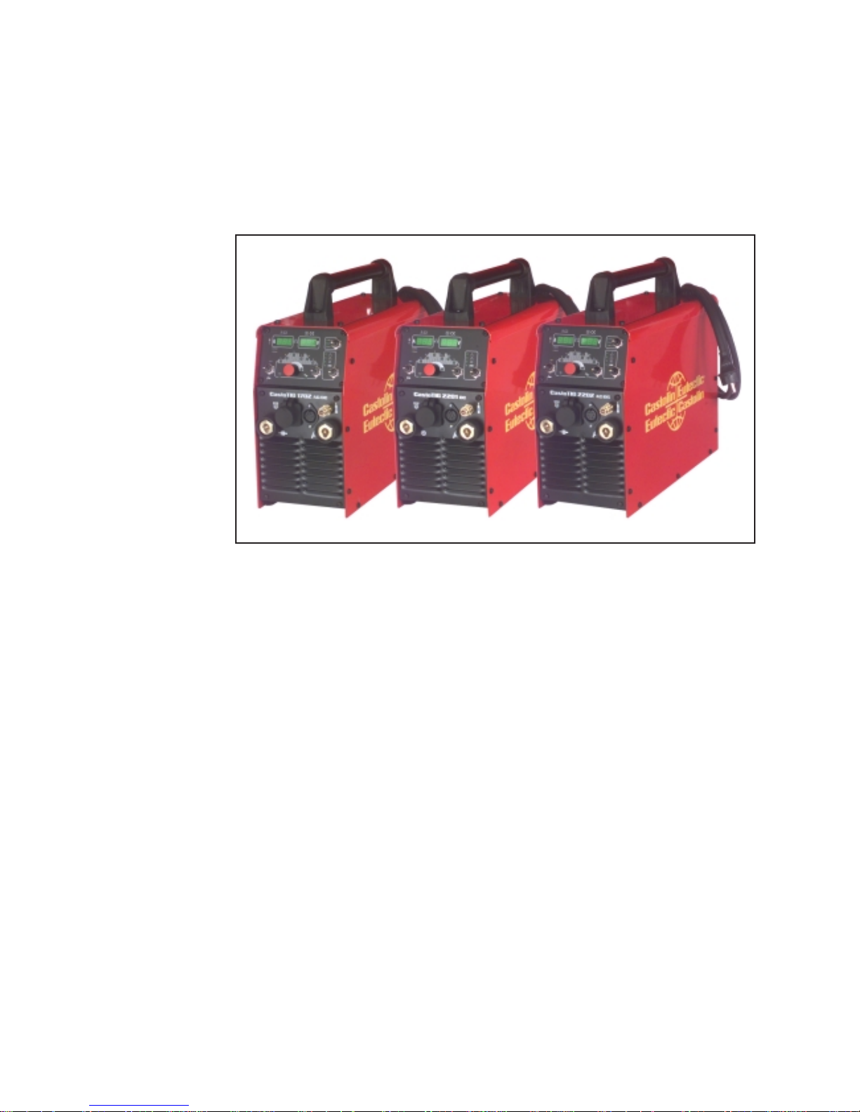
The CastoTIG 1702 AC/DC, CastoTIG 2202 AC/DC and CastoTIG 2201 DC belong to a
new generation of TIG power sources. Among their outstanding features are superlative
precision in the welding process, exact replicability of all results, and superb welding
properties. Alongside the welding properties, the high degree of efficiency is another key
feature of the technology incorporated in the new TIG power sources.
Fig.1 CastoTIG 1702 AC/DC, CastoTIG 2201 DC and CastoTIG 2202 AC/DC power sources
Work with the new power sources is made even easier by their self-explanatory, “intuitive” operating concept. Despite the wealth of features with which the machines are
loaded, the welder can see the key functions “at a glance” and adjust them accordingly.
In the workshop and industrial fields there are innumerable areas of application for the
CastoTIG 1702 AC/DC, CastoTIG 2202 AC/DC and CastoTIG 2201 DC. As regards their
suitability for welding different materials, they are just as much “at home” welding unalloyed and low-alloy steel as they are welding high-alloy chrome-nickel steels.
Moreover, the CastoTIG 1702 AC/DC and CastoTIG 2202 AC/DC does sterling service
when it comes to welding aluminium, aluminium alloys and magnesium. The AC frequency can be adjusted over a very wide range, permitting optimum adaptation to your
particular requirements.
General remarks
Basic system
principle
Machine concept
Areas of utilisation

5
Minimum equipment needed for welding
General remarks
TIG-AC welding
TIG-DC welding
Rod electrode
(MMA) welding
Depending on which weld process you intend to use, a certain minimum level of equipment will be needed in order to work with the power source.
In the section below, you will find lists of what equipment is needed (as a minimum) for
welding with each of the weld processes.
- CastoTIG 1702/2202 AC/DC power source
- Grounding (earthing) cable
- TIG welding torch with rocker switch
- Gas connection (for supplying the machine with shielding gas), with pressure
regulator
- Filler metal (depending on the application)
- CastoTIG 1702/2202 AC/DC or CastoTIG 2201 DC power source
- Grounding (earthing) cable
- TIG welding torch with rocker switch
- Gas connection (for supplying the machine with shielding gas)
- Filler metal (depending on the application)
- CastoTIG 1702/2202 AC/DC or CastoTIG 2201 DC power source
- Grounding (earthing) cable
- Electrode holders
- Rod electrodes (as required by the application)

6
Electrode cable
Grounding (earthing) cable
Fig.2 System add-ons and options
Trolley, and gascylinder holders
Remote control unit
Power source
Cooling unit
TIG welding torch:
Standard / Up/Down
RC F pedal remote
control unit
System components
General remarks The CastoTIG 1702 AC/DC, CastoTIG 2202 AC/DC and CastoTIG 2201 DC power
sources can be run with numerous different system add-ons and options.
Overview
7
4. Alter the parameter
The key feature of the control panel is the logical way in which the controls are arranged.
All the main parameters needed for day-to-day working can easily be
- selected with the buttons
- altered with the adjusting dial
- shown on the display during welding.
Note! Owing to software updates, you may find that your machine has certain
functions that are not described in these Operating Instructions, or vice-versa.
Also, certain illustrations may be very slightly different from the actual controls
on your machine. However, these controls function in exactly the same way.
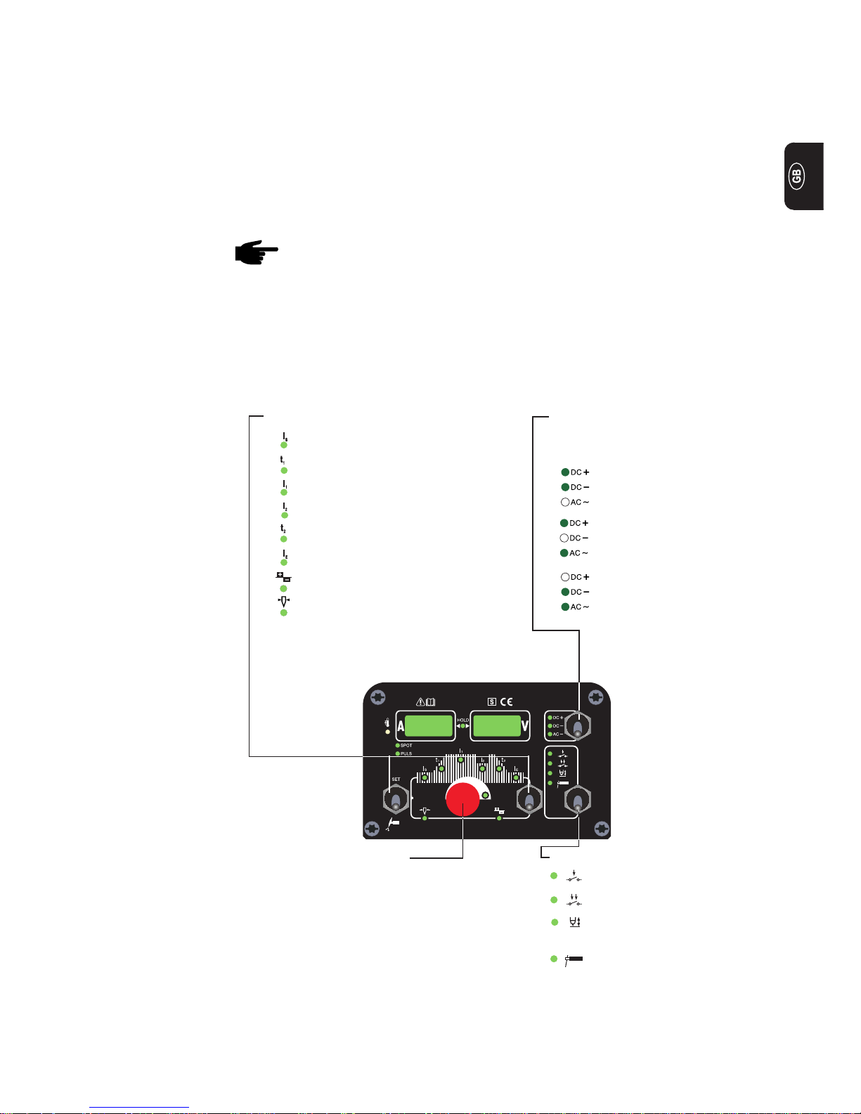
The illustration below shows an overview of the main settings needed for day-to-day
working, based on the example of the CastoTIG 1702/2202 AC/DC and CastoTIG 2201
DC control panel. You will find a detailed description of these settings in the following
section (“Control panel”).
1. Select the operating mode:
Rod electrode (MMA)
Contact ignition
(Lift-arc)
4-step mode
2-step mode
2. Choose which process:
(only on CastoTIG 1702/2202 AC/
DC)
DC+ welding
(only with rod electrode)
DC- welding
AC welding
3. Select the parameter:
Starting current I
S
Upslope t
1
Main current I
1
Reduced current I
2
Downslope t
2
Final current I
E
Balance (only with TIG-AC)
Electrode diameter
Control panel
Overwiew
8
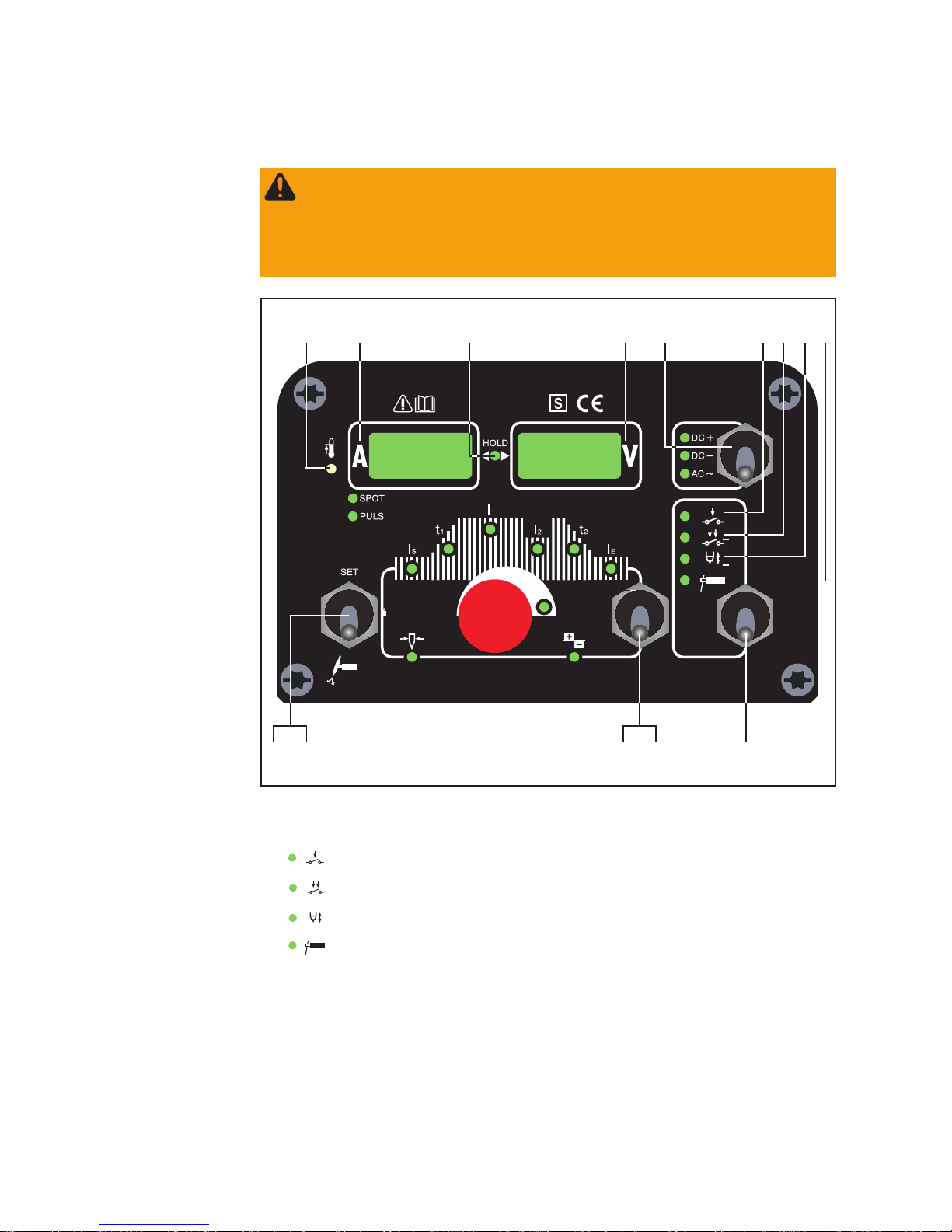
CastoTIG 1702/
2202 AC/DC
control panel
Fig.3 CastoTIG 1702/2202 AC/DC control panel
(6)(15) (12)(10)
(2) (3) (5)(4)
(1)(9)(14)(13) (7)
(1) Mode button ... for selecting the operating mode
(2) 2-step mode
(3) 4-step mode
(4) Contact ignition (Lift-arc)
(5) Rod electrode (MMA) welding
Important! If you select the “Rod electrode (MMA) welding” mode (5), the welding
voltage will only be available after a 3-second time-lag.
(8)
(11)
In this section, the control panels of the CastoTIG 1702/2202 AC/DC and CastoTIG
2201 DC power sources will be dealt with separately.
General remarks
Warning! Operating the equipment incorrectly can cause serious injury and
damage. Do not use the functions described here until you have read and completely understood all of the following documents:
- these Operating Instructions
- all "Operating Instructions" for the system components, especially the
"Safety rules"
 Loading...