

Page 1

SOHOSpeed ADSL2/2+ Ethernet/Wireless Gateway User’s Manual
AADDSSLL22//22++EEtthheerrnneett//W
Wiirreelleessss
OHH
SSO
UUsseerr’’ssM
OSSppeeeedd
O
Gaattee
G
Maann
waayy
w
uaall
u
Revision 1.0
July 2006
0
Page 2

SOHOSpeed ADSL2/2+ Ethernet/Wireless Gateway User’s Manual
FCCInformation
FCC Radiation Exposure Statement
This equipment complies with FCC radiation exposure limits set forth for an
uncontrolled environment.
This equipment should be installed and operated with minimum distance
20cm between the radiator & your body.
This transmitter must not be co-located or operating in conjunction with any
other antenna or transmitter.
FCC Warning
This device complies with part 15 of the FCC Rules. Operation is subject to
the following two conditions:
1. This device may not cause harmful interference.
2. This device must accept any interference received, including interference
that may cause undesired operation.
This equipment has been tested and found to comply with the limits for a
Class B digital device, pursuant to part 15 of the FCC Rules. These limits are
designed to provide reasonable protection against harmful interference in a
residential installation. This generates, uses and can radiate radio frequency
energy and, if not installed and used in accordance with the instructions, may
cause harmful interference to radio communications. However, there is no
guarantee that interference will not occur in a particular installation. If this
equipment does cause harmful interference to radio or television reception,
which can be determined by turning equipment off and on, the user is
encouraged to try to correct the interference by one or more of the following
measures:
y Reorient or relocate the receiving antenna.
y Increase the separation between the equipment and receiver.
y Connect the equipment into an outlet on a circuit different from that to
which the receiver is connected.
y Consult the dealer or an experienced radio/TV technician for help.
Notice: The Part 15 radio device operates on a non-interference basis with
other devices operating at this frequency. Any changes or modification not
expressly approved by the party responsible could void the user’s authority to
operate the device.
CE Mark Warning
This is a Class B product. In a domestic environment, this product may cause
radio interference in which case the user may be required to take adequate
measures.
1
Page 3

SOHOSpeed ADSL2/2+ Ethernet/Wireless Gateway User’s Manual
Warranty
Items sold by manufacturer/distributor/agent, hereinafter called "Seller", are
warranted only as follows: Except as noted below Seller will correct, either by
repair or replacement at its option, any defect of material or workmanship
which develops within one year after delivery of the item to the original Buyer
provided that evaluation and inspection by Seller discloses that such defect
developed under normal and proper use. Repaired or replaced items will be
further warranted for the unexpired term of their original warranty. All items
claimed defective must be returned to Seller, transportation charges prepaid,
and will be returned to the Buyer with transportation charges collect unless
evaluation proves the item to be defective and that the Seller is responsible
for the defect. In that case, Seller will return to Buyer with transportation
charge prepaid. Seller may elect to evaluate and repair defective items at the
Buyer's site. Seller may charge Buyer a fee (including travel expenses, if
needed) to cover the cost of evaluation if the evaluation shows that the items
are not defective or that they are defective for reasons beyond the scope of
this warranty.
The Seller makes no warranty concerning components or accessories not
manufactured by it. However, in the event of failure of such a part, Seller will
give reasonable assistance to Buyer in obtaining from the manufacturer
whatever adjustment is reasonable in light of the manufacturer's own warranty.
Seller will not assume expense or liability for repairs made outside the factory
by other than Seller's employees without Seller's written consent.
SELLER IS NOT RESPONSIBLE FOR DAMAGE TO ANY ASSOCIATED
EQUIPMENT, NOR WILL SELLER BE HELD LIABLE FOR INCIDENTAL,
CONSEQUENTIAL, OR OTHER DAMAGES. THIS WARRANTY IS IN LIEU
OF ALL OTHER WARRANTIES EXPRESSED OR IMPLIED INCLUDING
THE IMPLIED WARRANTY OF "MERCHANTABILITY" AND "FITNESS FOR
PARTICULAR PURPOSE."
Trademarks
All trademarks are the property of their respective owners.
2
Page 4

SOHOSpeed ADSL2/2+ Ethernet/Wireless Gateway User’s Manual
Table of Contents
1. INTRODUCTION................................................................................................ 5
1.1 F
1.2 S
EATURES ......................................................................................................5
PECIFICATION............................................................................................... 6
2. SOHOSPEED OVERVIEW ...............................................................................7
2.1 P
2.2 LED D
ORTS AND BUTTONS .................................................................................... 7
ESCRIPTION ........................................................................................ 8
2.3 INSTALLING YOUR SOHOSPEED ................................................................... 8
3. SETTING UP YOUR SOHOSPEED ................................................................. 9
3.1 L
3.2 H
3.3 S
OG INTO YOUR SOHOSPEED ..................................................................... 9
OME PAGE .................................................................................................10
ETUP .......................................................................................................... 11
3.3.1 Wide Area Network (WAN) Connection ..............................................11
3.3.2 Local Area Network (LAN) Connection............................................... 11
3.4 C
ONFIGURING THE WAN ............................................................................. 12
3.4.1 Setup a WAN Connection (New Connection).......................................12
3.4.2 Tow Step PVC ......................................................................................24
3.4.3 Modify an Existing Connection............................................................25
3.4.4 Modem Setup........................................................................................ 26
3.5 C
ONFIGURING THE LAN............................................................................... 27
3.5.1 LAN Group Configuration ................................................................... 30
3.5.2 Ethernet Switch Configuration ............................................................33
3.6 C
ONFIGURING THE WLAN...........................................................................34
3.6.1 WIRELESS Setup .................................................................................34
3.6.2 Wireless Configuration ........................................................................ 36
3.6.3 Multi SSID............................................................................................37
3.6.4 Wireless Security..................................................................................39
3.6.5 Wireless Management..........................................................................43
3.6.6 WDS .....................................................................................................44
3.7 ADVANCED ............................................................................................... 46
3.7.1 UPnP....................................................................................................46
3.7.2 SNTP ....................................................................................................47
3.7.3 SNMP ................................................................................................... 48
3.7.4 TR-069..................................................................................................50
3.7.5 Port Forwarding .................................................................................. 51
3.7.6 IP Filters .............................................................................................. 57
3.7.7 LAN Clients..........................................................................................60
3.7.8 LAN Isolation .......................................................................................62
3.7.9 TR-068 WAN Access ............................................................................63
3.7.10 Bridge Filters .......................................................................................64
3.7.11 Web Filters...........................................................................................66
3.7.12 Dynamic DNS Client............................................................................67
3.7.13 IGMP Proxy .........................................................................................68
3.7.14 Static Routing.......................................................................................72
3.7.15 Dynamic Routing .................................................................................74
3.7.16 Policy Routing...................................................................................... 76
3.7.17 Ingress..................................................................................................79
3
Page 5

SOHOSpeed ADSL2/2+ Ethernet/Wireless Gateway User’s Manual
3.7.18 Egress................................................................................................... 86
3.7.19 Shaper ..................................................................................................88
3.7.20 Web Access Control .............................................................................90
3.7.21 SSH Access Control .............................................................................92
3.8 T
OOLS ..........................................................................................................93
3.8.1 System Commands ...............................................................................93
3.8.2 Remote Log - Router ............................................................................ 94
3.8.3 Remote Log - Voice..............................................................................95
3.8.4 User Management................................................................................96
3.8.5 Update SOHOSpeed.............................................................................97
3.8.6 Ping Test ..............................................................................................98
3.8.7 Modem Test..........................................................................................99
3.9 STATUS....................................................................................................100
3.9.1 Network Statistics...............................................................................101
3.9.2 Connection Status ..............................................................................101
3.9.3 DDNS Update Status..........................................................................102
3.9.4 DHCP Clients ....................................................................................103
3.9.5 Modem Status.....................................................................................104
3.9.6 Product Information...........................................................................104
3.9.7 System Log .........................................................................................105
3.9.8 WDS Report .......................................................................................105
APPENDIX: TROUBLESHOOTING ...................................................................106
4
Page 6

SOHOSpeed ADSL2/2+ Ethernet/Wireless Gateway User’s Manual
1. Introduction
The SOHOSpeed ADSL2/2+ Ethernet/Wireless Gateway is a high-speed WAN bridge/router
that is specifically designed to connect to the Internet and to directly connect to your local
area network (LAN) via universal serial bus (USB), wireless LAN (WLAN), or high speed
10/100 Mbps Ethernet. The SOHOSpeed also has full Network Address Translation (NAT)
firewall, demilitarized zone (DMZ) services, and WLAN security support to block unwanted
users from accessing your network. Quality of Service (QoS) and Policy routing (PR) are also
supported.
The SOHOSpeed is fully compatible with PCs and Apple Macs. It also supports 802.11b/g
and the following wireless security protocols: WEP, WPA, WPA2, and 802.1x.
1.1 Features
zEquipped with four 10/100 Ethernet ports
zEquipped with one USB Interface
zEquipped with two telephone ports
zEquipped with IEEE 802.11b/g WLAN AP
zHigh speed wireless connection, up to 54 Mbps
zConnects multiple PCs to the Internet with just one WAN IP Address (when configured in
router mode with NAT enabled)
zConfigurable through user-friendly web pages
zSupports Single-Session IPSec and PPTP Pass-Through for Virtual Private Network
(VPN)
zSeveral popular games are already pre configured. Just enable the game and the port
settings are automatically configured.
zConfigurable as a DHCP Server on Your Network
zCompatible with virtually all standard Internet applications
zIndustry standard and interoperable DSL interface
zAddress Filtering, DMZ Hosting, and Much More
zSupport 64, 128 and 256 bits WEP / WPA / WPA-PSK / 802.1x (wireless models)
zSimple web based status page displays a snapshot of your system configuration, and
links to the configuration pages
zDownloadable flash software upgrades
zSupport for up to 8 Permanent Virtual Circuits (PVC)
zSupport for up to 8 PPPoE sessions
zSupports Classical IP over ATM (CLIP or also referred to as RFC1577)
zCost effective extension ADSL2+ modem design to full-featured ADSL and WLAN router
zSystem management includes SNMP v1 and v2 command line interface and web
interface
zBrowse the Internet while talking on the phone simultaneously
5
Page 7

SOHOSpeed ADSL2/2+ Ethernet/Wireless Gateway User’s Manual
1.2 Specification
ADSL Compliance
zSupport Multi mode standards (ANSI T1.413 Issue 2, G.dmt, G.lite)
zADSL2 G.dmt.bis (G.992.3)
zADSL2 G.lite.bis (G.992.4)
zADSL2+ (G.992.5)
zReach Extended ADSL (RE ADSL)
ATM Protocols
z8 PVC Support
zAdaptation Layers AAL5, AAL2 and AAL0 Support
zOAM F4/F5 Loop Back
PPP Support
zPPP over ATM PVC (RFC 2364&RFC1577)
zPPP over Ethernet (RFC 2516)
zPAP (Password Authentication Protocol), CHAP (Challenge Handshake Authentication
Protocol) and MS-CHAP (Microsoft Challenge Handshake Authentication Protocol)
Bridge Mode
zRFC 1483 Bridge
zIEEE 802.1D transparent bridging
zBridge Filtering
Router Mode
zRFC 1483 Route
zIPoA (RFC1577)
zRIP 1 & 2 supported
zDHCP (RFC1541) Server, Relay and Client
zNetwork Address Translation (NAT)/ Network Address Port Translation (NAPT)
zDNS relay
zIGMP v1 and v2
zToS supported
Quality of Service (QoS)
zConstant Bit Rate (CBR), Real-Time Variable Bit Rate (VBR-rt)
zNon-Real-Time Variable Bit Rate (VBR-nrt)
zUnspecified Bit Rate (VBR)
Management
zRemote / Local configuration & management
zWeb / Telnet configuration & management
zFirmware upgrade through web management
Wireless Specification
zStandard
IEEE 802.11b/g for wireless LAN
zFrequency Band
2.400 ~ 2.4835 GHz ISM Band
zSpreading
DSSS (Direct Sequence Spread Spectrum)
zSecurity
64/128-bit WEP Encryption
zOperating Range
Open Space: 100 - 300m; Indoor: 35m - 100m
zSupported Bit Rate
54M, 48M, 36M, 24M, 18M, 12M, 11M, 9M, 6M, 5.5M, 2M, 1Mbps
zModulation
OFDM, CCK
6
Page 8
SOHOSpeed ADSL2/2+ Ethernet/Wireless Gateway User’s Manual
2. SOHOSpeed Overview
Your SOHOSpeed has many ports, switches and LEDs. The features are listed below.
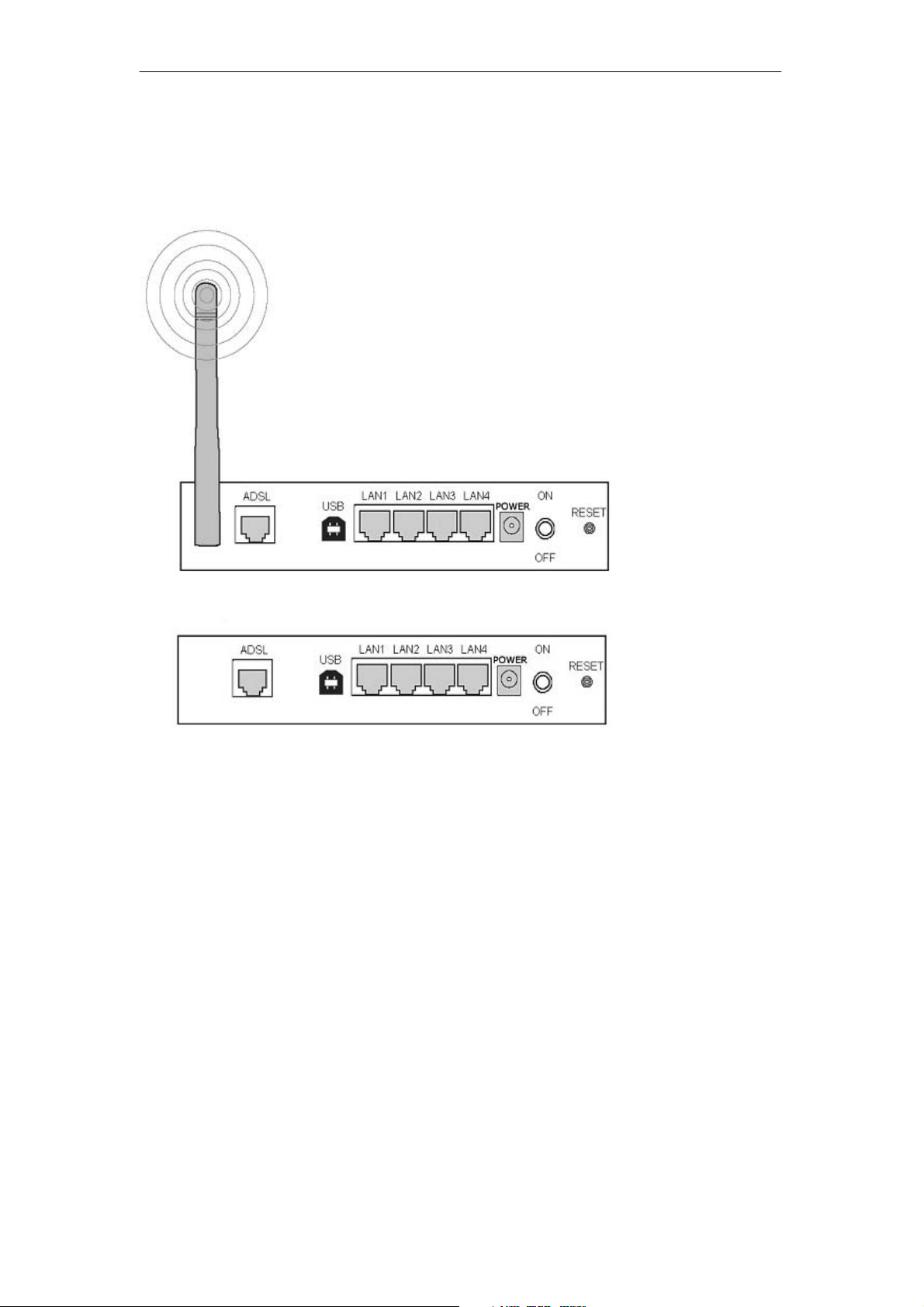
2.1 Ports and Buttons
(4 Ports Wireless Gateway)
RESET: The RESET button will set the SOHOSpeed to its factory default setting and reset
the SOHOSpeed. You may need to place the SOHOSpeed into its factory defaults if the
configuration is changed, you loose the ability to enter the SOHOSpeed via the web interface,
or following a software upgrade, and you loose the ability to enter the SOHOSpeed. To reset
the SOHOSpeed, simply press the reset button for more than 10 seconds. The SOHOSpeed
will be reset to its factory defaults and after about 30 seconds the SOHOSpeed will become
operational again.
POWER: Connect the power adapter that came the SOHOSpeed. Using a power supply with
a different voltage rating will damage this product. Make sure to observe the proper power
requirements. The power requirement is 12 volts.
LAN (local area network) port(s): Connect to Ethernet network devices, such as a PC, hub,
switch, or router.
(4 Ports Ethernet Gateway)
USB (universal serial port): Connects this port to a PC’s USB port. The SOHOSpeed only
supports Window’s based PCs via a RNDIS driver (included in the software).
ADSL port: This is the WAN interface which connects directly to your phone line.
7
Page 9
SOHOSpeed ADSL2/2+ Ethernet/Wireless Gateway User’s Manual
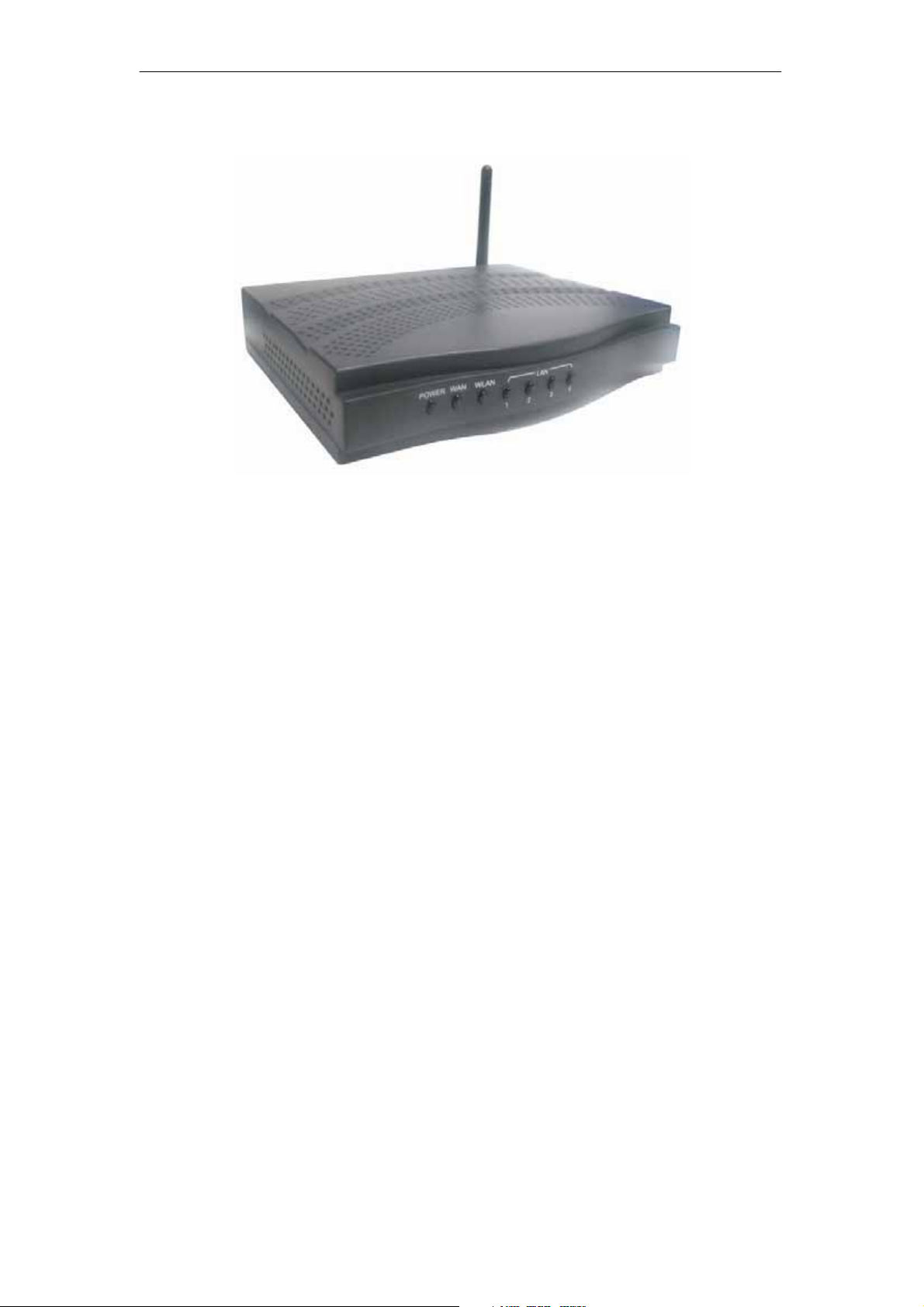
2.2 LED Description
Power LED: The LED stays lighted to indicate the system is power on properly.
WAN LED: This LED is lighted when the WAN connection is established and flashes when
the WAN port is sending/receiving data.
WLAN LED: This LED is lighted when a wireless link is established and flashes when the
data is sending/receiving via wireless.
PPP LED: This LED is lighted when a PPP link is established and flashes when the data is
sending/receiving via PPP. (Ethernet models)
LAN LED: The LED is lighted when a connection is established to LAN port and flashes when
LAN port is sending/receiving data. (The number of LAN ports depends on your model.)
USB LED: The LED is lighted when a connection is established to USB port and flashes
when USB port is sending/receiving data.
2.3 Installing your SOHOSpeed
Locate an optimum location for the SOHOSpeed.
1.
2. For connections to the Ethernet and DSL interfaces, refer to the Quick Installation Guide.
3. Connect the AC Power Adapter. Depending upon the type of network, you may want to
put the power supply on an uninterruptible supply. Only use the power adapter supplied
with the SOHOSpeed. A different adapter may damage the product.
Now that the hardware installation is complete, continue on to set up your SOHOSpeed.
8
Page 10
SOHOSpeed ADSL2/2+ Ethernet/Wireless Gateway User’s Manual
3. Setting up Your SOHOSpeed
This section guides you through configuring your SOHOSpeed. The SOHOSpeed is shipped
with a standard default bridge configuration. Most users would want to change the
SOHOSpeed from a bridge to a router.
Before setting up your SOHOSpeed, make sure you have followed the Quick Start Guide.
You should have your computers configured for DHCP mode and have proxies disabled on
your browser. If you access the router using your web browser and see a log-in redirection
page instead of the Log In page, check your browser’s settings to verify that JavaScript is
enabled. Also, if you do not get the page as shown below, you may need to delete your
temporary Internet files by flushing the cached web pages.
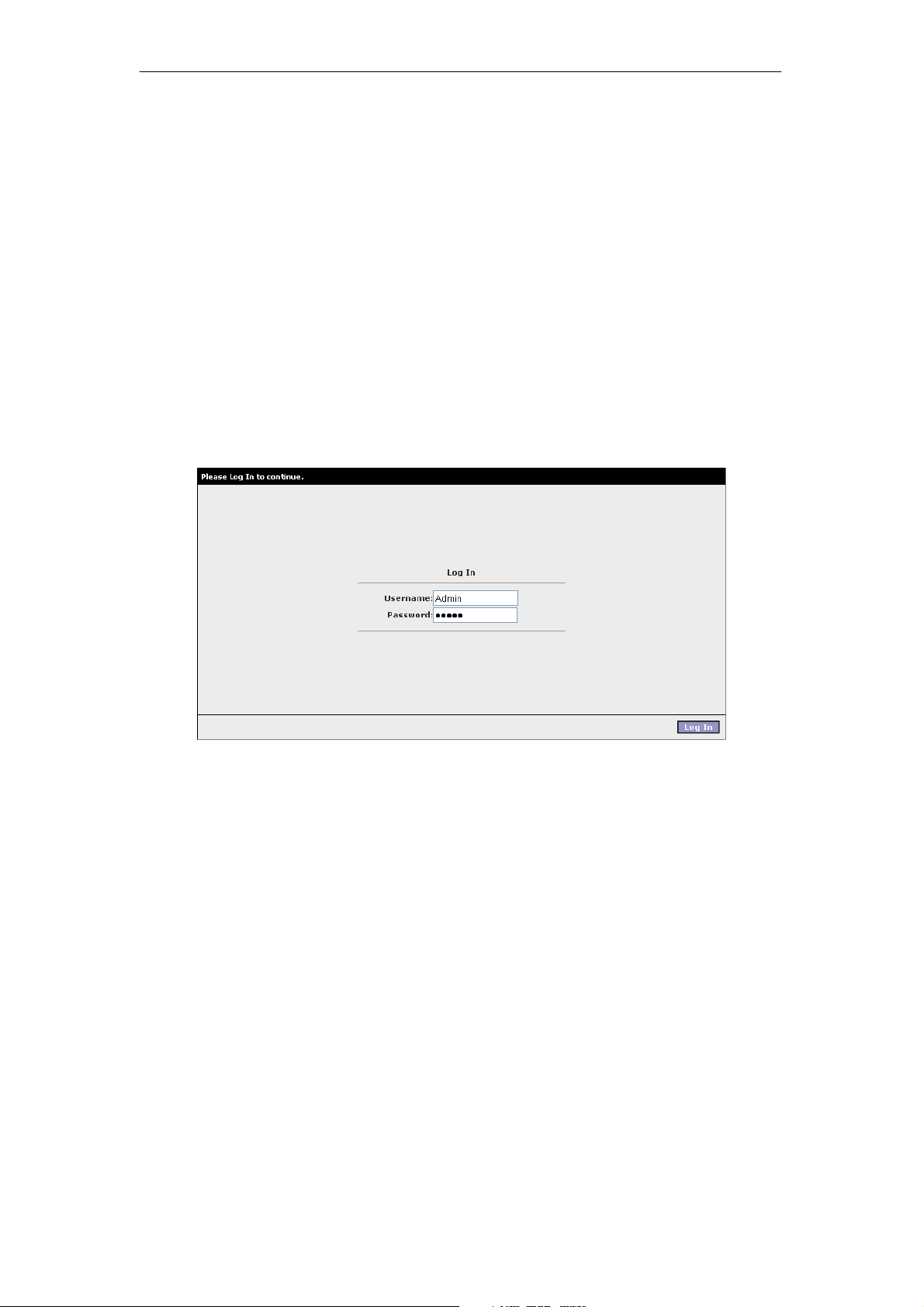
3.1 Log into Your SOHOSpeed
Use the following procedures to log in to your SOHOSpeed.
1. Open your web browser.
You may get an error message. This is normal. Continue on to the next step.
2. Type the default IP address of the SOHOSpeed 192.168.1.1 and press Enter.
The Log In page appears.
3. Enter the following information:
z User Name: Admin
z Password: Admin
Note: Both fields are case-sensitive. Admin is the default value. The login name and
password can be changed later on using the Tools/User Management menu options.
4. Click Log In.
The main page appears.
9
Page 11
SOHOSpeed ADSL2/2+ Ethernet/Wireless Gateway User’s Manual
3.2 Home Page
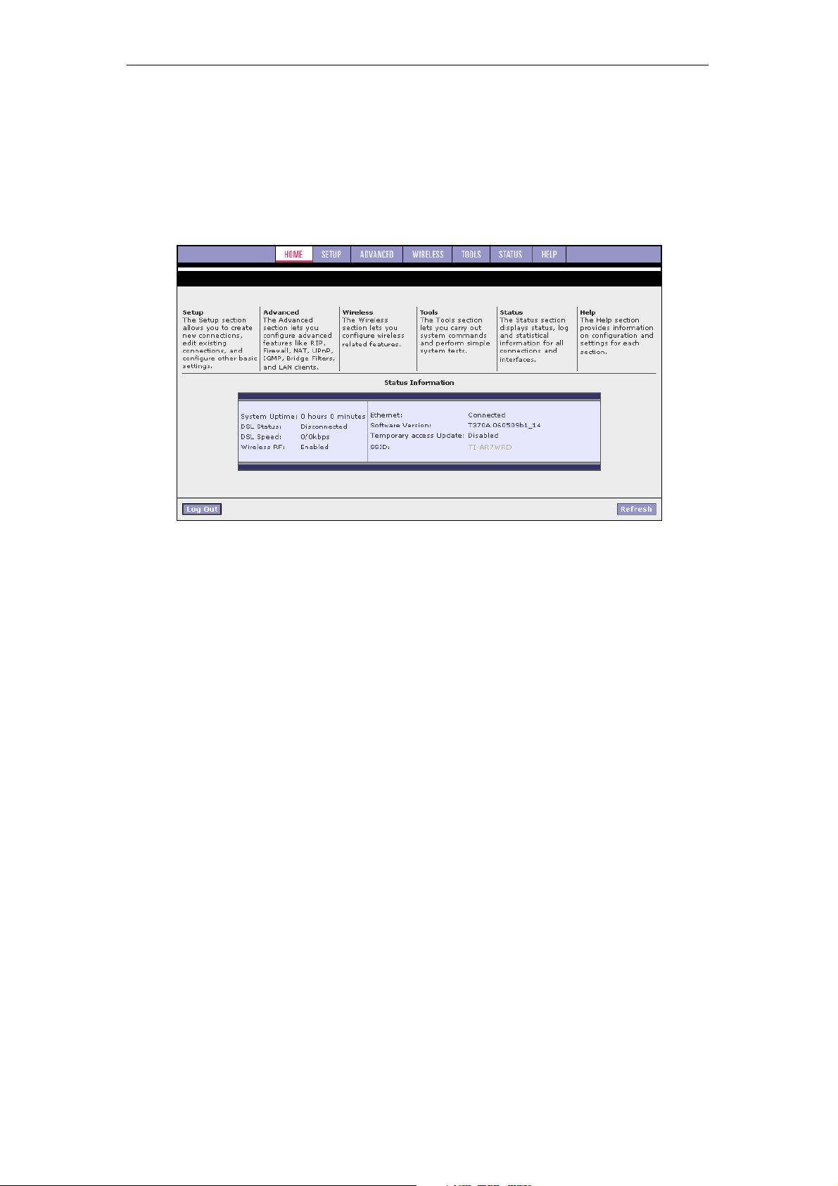
The first page is the Home page. From this page you can perform the following tasks:
z Setup the SOHOSpeed (configure the LAN and WAN connection(s).
z Configure the advanced configuration options within the SOHOSpeed (security, routing,
and filtering).
z Obtain the status of the SOHOSpeed.
z View the extensive online help.
The basic layout of the Home page consists of a page selection list across the top of the
browser window. The lower center part of the page displays the SOHOSpeed status,
connection information, and other useful information. The center part of the display provides
descriptions of the options supported on the other web interface pages.
10
Page 12
SOHOSpeed ADSL2/2+ Ethernet/Wireless Gateway User’s Manual
3.3 Setup
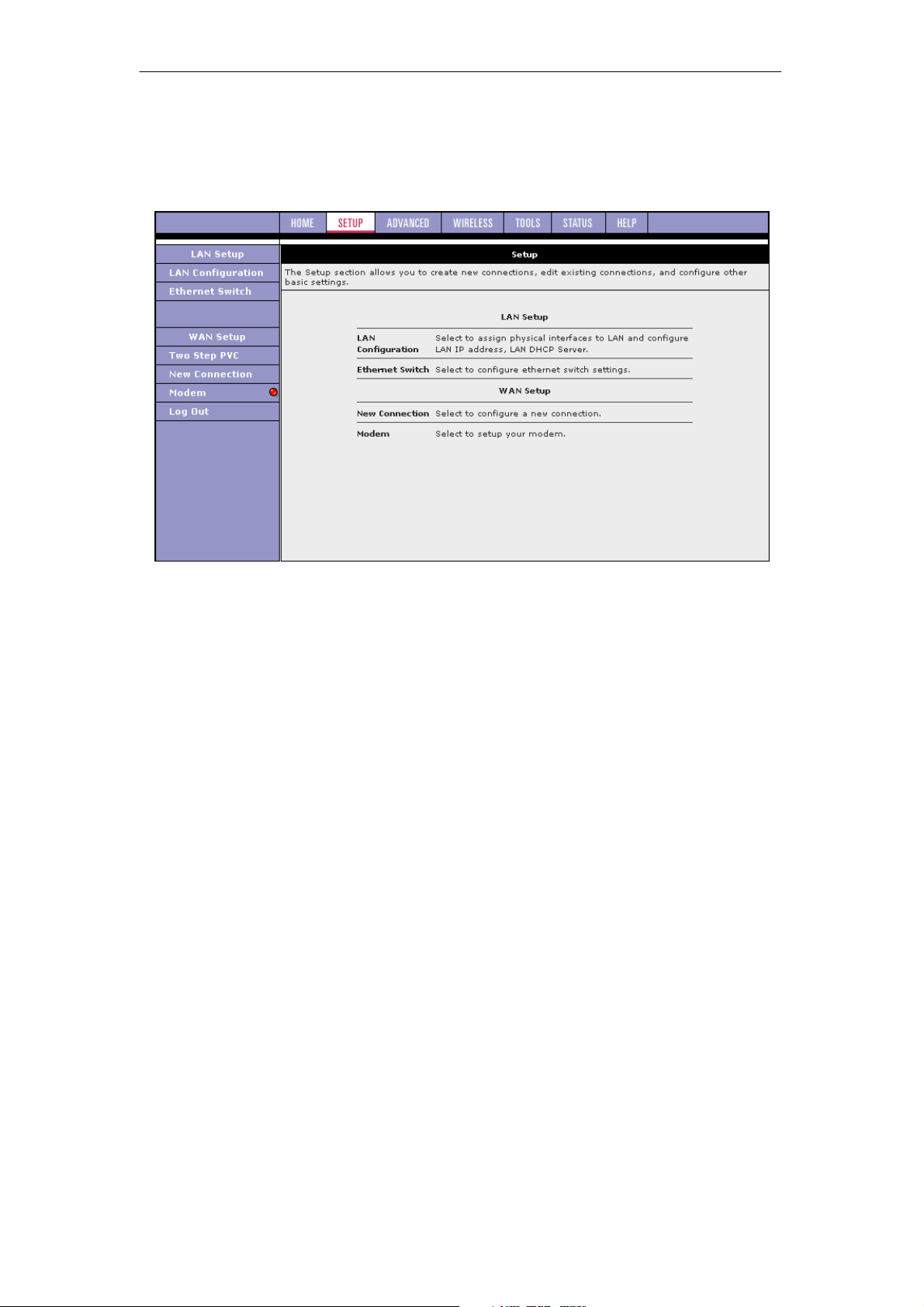
To setup your SOHOSpeed with a basic configuration, from the Main page, select Setup. The
figure below illustrates the Setup page. The page is divided into two subsections: the LAN
Setup and the WAN Setup.
Before configuring the SOHOSpeed, there are several concepts that you should be familiar
with on how your new SOHOSpeed works. Please take a moment to familiarize yourself with
these concepts, as it should make the configuration much easier.
3.3.1 Wide Area Network (WAN) Connection
On one side of the SOHOSpeed is the WAN interface, also referred to as a broadband
connection. This WAN connection is different for every WAN service provider. Most of the
configuration you perform is for the WAN connection.
3.3.2 Local Area Network (LAN) Connection
On the other side of the SOHOSpeed are LAN interfaces. This is where local hosts are
connected. The SOHOSpeed is normally configured to automatically provide all the hosts on
the LAN network with IP addresses.
11
Page 13

SOHOSpeed ADSL2/2+ Ethernet/Wireless Gateway User’s Manual
3.4 Configuring the WAN
Before the SOHOSpeed passes any data between the LAN interfaces and the WAN interface,
the WAN side of the SOHOSpeed must be configured.
You need some (or all) of the information outlined below before you can properly configure
the WAN:
z Your DSL line virtual path identifier (VPI) and virtual channel identifier (VCI)
z Your DSL encapsulation type and multiplexing
z Your DSL training mode (default is MultiMode)
For PPPoA or PPPoE users, you also need these values from your ISP:
z Your username and password
For RFC 2684 Static connections, you may need these values from your ISP:
z Your fixed WAN IP address
z Your subnet mask
z Your default gateway
z A set of three DNS IP addresses
Since multiple users can use the SOHOSpeed, the SOHOSpeed can simultaneously support
multiple connection types; hence, you must set up different profiles for each connection. The
SOHOSpeed supports the following protocols:
z RFC 2516 PPPoE
z RFC 2364 PPPoA
z RFC 2684 Static
z Dynamic host configuration protocol (DHCP)
z Bridged
z RFC 2225 classical IP over ATM (CLIP)
You can create up to eight WAN connections.
3.4.1 Setup a WAN Connection (New Connection)
A new WAN connection is a virtual connection over the physical DSL connection. Your
SOHOSpeed can support up to eight different (unique) virtual connections. If you have
multiple different virtual connections, you may need to use the static and dynamic routing
capabilities of the SOHOSpeed to pass data correctly.
Before you make a new WAN connection, you should make sure you have an available DSL
connection.
PPPoE
PPP, or point-to-point protocol, is a method of establishing a network connection/session
between network hosts. PPPoE is a protocol for encapsulating PPP frames in Ethernet
frames and is described in RFC 2516.
PPPoE provides the ability to connect to a network of hosts over a simple bridging access
device to a remote access concentrator. With this model, each SOHOSpeed uses its own
PPP stack. Access control, billing, and type of service control can all be done on a per-user
rather than per-site basis.
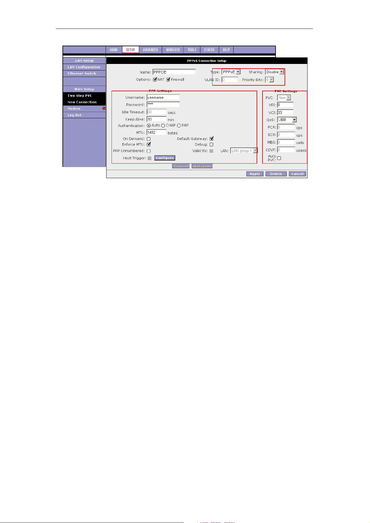
The default New Connection Setup page, which defaults to the PPPoE Connection Setup
page. Notice this page can be logically divided into three sections:
z Section A includes settings specific to the connection type
z Section B (VLAN settings)
z Section C (PVC settings) remains the same for all six connection types.
For other connection types, we will focus on the fields in Section A.
12
Page 14
SOHOSpeed ADSL2/2+ Ethernet/Wireless Gateway User’s Manual
1. At the Setup main page, click New Connection.
The default PPPoE Connection Setup page is displayed.
2. In the Name field, enter a unique name for the PPPoE connection.
The name must not have spaces and cannot begin with numbers. In this example, the
unique name is PPPoE.
3. The Network Address Translation (NAT) and the Firewall options are enabled by
default. Leave these in the default mode.
Note: NAT enables the IP address on the LAN side to be translated to IP address on the
WAN side. If NAT is disabled, you cannot access the Internet.
4. If you want to enable VLAN, refer to the table below to configure the following fields:
z Sharing: Select VLAN to enable the VLAN ID and Priority Bits fields.
z VLAN ID: Enter the VLAN ID.
z Priority Bits: Select the priority bits of the VLAN.
5. In the PPP Settings section, enter values from DSL service provider or your ISP.
6. In the PVC Settings section, enter values for the VPI and VCI.
Note: Your DSL service provider or your ISP supplies these values. In this example, the
DSL service provider is using 0,33.
7. Select the Quality of Service (QoS).
Leave the default value if you are unsure or if the ISP did not provide this information.
8. Click Apply to complete the connection setup. This temporarily activates this connection.
13
Page 15
SOHOSpeed ADSL2/2+ Ethernet/Wireless Gateway User’s Manual
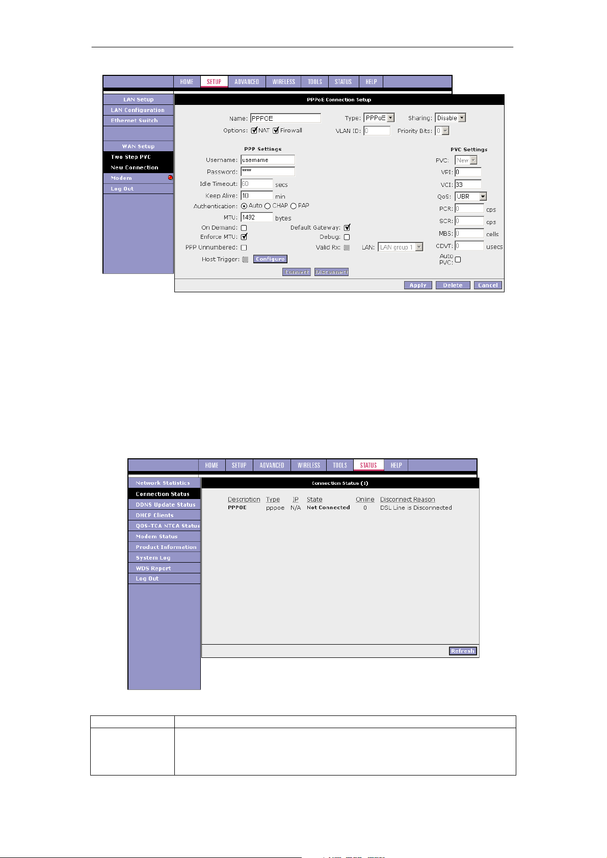
A new link is created for this connection in the left-hand column. You can connect,
disconnect, apply, delete, or cancel this connection using the buttons at the bottom of
this page.
Note: The changes take effect when you click Apply; however, if the SOHOSpeed
configuration is not saved, these changes will be lost upon SOHOSpeed reboot.
9. To make the change permanent, click Tools at the top of the page and select System
Commands.
10. At the System Commands page, click Save All.
11. To check the status, click Status at the top of the page and select Connection Status.
The figure below shows the Connection Status page.
Field Description
Field Definition/Description
Username
Your user name for the PPPoE access provided by your DSL service
provider or your ISP. This field is alpha-numeric and the maximum length is
64 characters. It cannot start with a number. The character type restrictions
do not apply for CLI-based configuration.
14
Page 16

SOHOSpeed ADSL2/2+ Ethernet/Wireless Gateway User’s Manual
Password
Idle Timeout
Keep Alive
Authentication
MTU
On Demand
Default Gateway
Enforce MTU
Debug
PPP
Unnumbered
LAN
Your password for the PPPoE access provided by your DSL service
provider or your ISP. This field is alpha-numeric and the maximum length is
128 characters. The character type restrictions do not apply for CLI-based
configuration.
Specifies that PPPoE connection should disconnect if the link has no
activity detected for n seconds. This field is used in conjunction with the
On-Demand feature and is enabled only when the On Demand field is
checked. To ensure that the link is always active, enter a 0 in this field.
You can also enter a value larger than 10 (secs).
When the On Demand option is not enabled, this value specifies the time
to wait without being connected to your provider before terminating the
connection. To ensure that the link is always active, enter a 0 in this field.
You can also enter any positive integer value in this field.
Three authentication options are available:
z Auto
z Challenge handshake authentication protocol (CHAP)
z Password authentication protocol (PAP)
Microsoft CHAP v2 is also supported in the Auto and CHAP options.
However, MS CHAP v1 is not supported.
Maximum transmit unit the DSL connection can transmit. It is a negotiated
value that packets of no more than n bytes can be sent to the service
provider. The PPPoE interface default MTU is 1492 (max) and PPPoA
default MTU is 1500 (max). The minimum MTU value is 64.
Enables On Demand mode. The connection disconnects if no activity is
detected after the specified idle timeout value. When checked, this field
enables the following fields:
z Idle Timeout
z Host Trigger
z Valid Rx
If checked, this WAN connection acts as the default gateway to the
Internet.
This feature is enabled by default. It forces all TCP traffic to conform with
PPP MTU by changing TCP maximum segment size to PPP MTU. If it is
disabled, you may have issues accessing some Internet sites.
Enables PPPoE connection debugging facilities. This option is used by ISP
technical support and ODM/OEM testers to simulate packets going through
the network from the WAN side.
PPP Unnumbered is a special feature. It enables the ISP to designate a
block of public IP addresses to the customer where it is statically assigned
on the LAN side. PPP Unnumbered is, in essence, like a bridged
connection.
The LAN field is associated with the PPP Unnumbered field and is enabled
when the PPP Unnumbered field is checked. You can specify the LAN
group the packets need to go to when the PPP Unnumbered feature is
activated.
Field
Sharing
VLAN ID
Definition/Description
The following options are available:
z Disable: Disables connection sharing.
z Enable: Enables connection sharing.
z VLAN: The VLAN ID and Priority Bits fields are activated when VLAN is
selected, which enable you to create VLAN.
VLAN Identification. Multiple connections over the same PVC are supported,
which requires the WAN network to have VLAN support and for the DSLAMS and
Routers on the ISP to handle VLAN Tags.
Extended support is also available, which allows multiple connections to be
placed over the single PVC without VLAN support (VLAN Tag of 0 is this special
case). In this mode of operation, a received packet is flooded on all the
connections that reside over it.
15
Page 17

SOHOSpeed ADSL2/2+ Ethernet/Wireless Gateway User’s Manual
Priority
Bits
PVC
VPI
VCI
QoS
PCR
Priority is given to a VLAN connection from 0-7. All packets sent over the VLAN
connection have the Priority bits set to the configured value.
Permanent virtual circuit. This is a fixed virtual circuit between two users.
It is the public data network equivalent of a leased line. No call setup or clearing
procedures are needed.
Virtual path identifier, equivalent to the virtual path connection (VPC).
Virtual channel identifier. A 16-bit field in the header of an ATM cell. The VCI,
together with the VPI, is used to identify the next destination of a cell as it passes
through to the ATM switch.
Quality of service, a characteristic of data transmission that measures how
accurately and how quickly a message or data is transferred from a source host
to a destination host over a network. The three QoS options are:
z Undefined Bit Rate (UBR): When UBR is selected, the PCR, SCR, MBS,
and CDVT fields are disabled.
z Constant Bit Rate (CBR): When CBR is selected, the PCR and CDVT fields
are enabled.
z Variable Bit Rate (VBR): When VBR is selected, the PCR, SCR, MBS, and
CDVT fields are enabled.
Peak Cell Rate, measured in cells/sec, is the cell rate which the source may
never exceed.
SCR
MBS
CDVT
Auto PVC
Sustained cell rate, measured in cells/sec, is the average cell rate over the
duration of the connection.
Maximum burst size, a traffic parameter that specifies the maximum number of
cells that can be transmitted at the Peak Cell Rate.
Cell delay variation tolerance, the maximum amount of cell delay variation that
can be accommodated. Cell delay variation measures the random inter-arrival
times of cells within an ATM connection due to cell transfer delay caused by
buffering, multiplexing, and so on.
Auto-Sensing permanent virtual circuit. The overall operation of the auto-sensing
PVC feature relies on end-to-end OAM pings to defined PVCs. There are two
groups of PVCs: customer default PVCs which are defined by the OEM/ISP and
the backup PVCs. The customer default must have 0/35 as the first default PVC.
The backup list of PVCs must be of the following VPI/VCI: 0/35, 8/35, 0/43, 0/51,
0/59, 8/43, 8/51, and 8/59. The list of PVCs is defined in XML and is configurable.
The Auto-Sensing PVC feature itself is also configurable in that the auto-search
mechanism can be disabled.
Upon DSL synchronization, end-to-end OAM pings will be conducted for every
defined PVC. The result of the pings will be recorded in an array for later use to
determine the usability of the particular PVC for connectivity. This list helps the
PVC manage the available PVC for use, and needs to be synchronized with
connections made without Auto-Sensing PVC. Update to this list is performed for
any change in DSL synchronization.
During connection establishment, the PVC module will first search through the list
of defined default PVCs. If a PVC is found from the default list that is ping-able
and not in use, the PVC module will update for that particular PVC as in-use from
the list and continues processing. If a PVC is not found in the default, the backup
PVC list is used. If no PVC is found again, the module will let the end-user know
that no available VCC was found.
With the connection established, the PVC is stored in flash as the connection
default PVC. Therefore upon reboot, this PVC is automatically chosen as the
PVC for that connection. This saved PVC in environment space of flash overrides
16
Page 18
SOHOSpeed ADSL2/2+ Ethernet/Wireless Gateway User’s Manual
the PVC connection saved in XML configuration space of flash for that
connection. During the connection establishment processing, the saved PVC will
be checked to see whether a connection can be made with the PVC. If the PVC
is OAM ping-able, the connection process continues. If the PVC is not OAM pingable, the search for an available PVC starts. The process of PVC selection is the
same as described above.
The list of default PVCs and backup PVCs need to be global for the management
of all connections, non Auto-Sensing PVC connection, as well as, Auto-Sensing
PVC connections. These lists allow the end-users to establish connectivity
without keeping track of the PVC used.
PPPoA Connection Setup
PPPoA is also known as RFC 2364. It is a method of encapsulating PPP packets in ATM cells
that are carried over the DSL line. PPP, or point-to-point protocol, is a method of establishing
a network connection/session between network hosts. It usually provides a mechanism of
authenticating users. Logical link control (LLC) and virtual circuit (VC) are two different
methods of encapsulating the PPP packet. Contact your ISP to determine which
encapsulation is being used on your DSL connection.
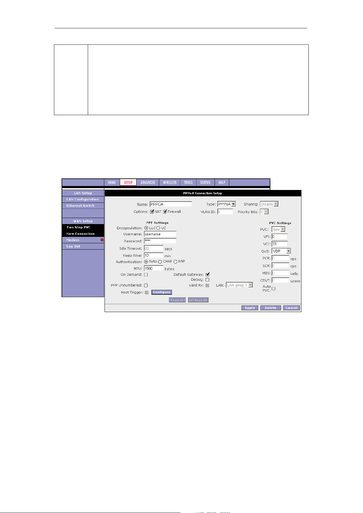
To configure the SOHOSpeed for PPPoA:
1. On the Setup main page, click New Connection.
The default PPPoE Connection Setup page isdisplayed.
2. From Type drop-down box, select PPPoA.
The default PPPoA Connection Setup page is displayed.
3. Enter a unique name for the PPPoA connection in the Name field.
The name must not have spaces and cannot begin with numbers. In this example, the
unique name is PPPoA.
4. The Network Address Translation (NAT) and the Firewall options are enabled by
default. Leave these in the default mode.
5. If you want to enable VLAN, refer to the table on section 3.4.1 to configure the following
fields:
z Sharing: Select VLAN to enable the VLAN ID and Priority Bits fields.
z VLAN ID: Enter the VLAN ID.
z Priority Bits: Select the priority bits of the VLAN.
6. In the PPP Settings section, select the encapsulation type (LLC or VC).
Note: If you are not sure, just use the default mode.
17
Page 19

SOHOSpeed ADSL2/2+ Ethernet/Wireless Gateway User’s Manual
7. In the PVC Settings section, enter values for the VPI and VCI.
Note: Your DSL service provider or your ISP supplies these values. In this example, the
DSL service provider is using 0,33.
8. Select the Quality of Service (QoS). Leave the default value if you are unsure or if the
ISP did not provide this information.
The PCR, SCR, MBS, and CDVT fields are enabled/disabled depending on the QoS
selection. Enter the values provided by the ISP or leave the defaults. Click Apply to
complete the connection setup. This temporarily activates this connection.
A new link has been created for this connection in the left-hand column. You can
connect, disconnect, apply, delete, or cancel this connection using this page by clicking
the Connection Name to return to its Connection Setup page.
Note: The changes take effect when you click Apply; however, if the SOHOSpeed
configuration is not saved, these changes will be lost upon SOHOSpeed reboot.
9. To make the change permanent, click Tools at the top of the page and select System
Commands.
10. At the System Commands page, click Save All.
11. To check the status, click Status and select Connection Status.
Field Description
Field
Encapsulation
Username
Password
Idle Timeout
Keep Alive
MTU
On Demand
Default Gateway
Definition/Description
The technique used by layered protocols in which a layer adds header
information to the protocol data unit (PDU) from the layer above. As an
example, in Internet terminology, a packet would contain a header from the
data link layer, followed by a header from the network layer (IP), followed
by a header from the transport layer (TCP), followed by the application
protocol data. Two options are provided: Logical Link Control (LLC) and
Virtual Channel (VC).
Your user name for the PPPoA access provided by your DSL service
provider or your ISP. This field is alpha-numeric and the maximum length is
64 characters. It cannot start with a number. The character type restrictions
do not apply for CLI-based configuration.
Your password for the PPPoA access provided by your DSL service
provider or your ISP. This field is alpha-numeric and the maximum length is
128 characters. The character type restrictions do not apply for CLI-based
configuration.
Specifies that the PPPoA connection should disconnect if the link has no
activity detected for n seconds. This field is used in conjunction with the On
Demand feature. To ensure that the link is always active, enter a 0 in this
field. You can also enter a value larger than 10 (secs).
When the On Demand option is not enabled, this value specifies the time
to wait without being connected to your provider before terminating the
connection. To ensure that the link is always active, enter a 0 in this field.
You can also enter any positive integer value in this field.
Authentication Three authentication options are available:
z Auto
z Challenge Handshake Authentication protocol (CHAP)
z Password Authentication Protocol (PAP)
Microsoft CHAP v2 is also supported in the Auto and CHAP options.
However, MS CHAP v1 is not supported.
Maximum transmit unit the DSL connection can transmit. It is a negotiated
value that packets of no more than n bytes can be sent to the service
provider. The PPPoE interface default MTU is 1492 (max) and PPPoA
default MTU is 1500 (max). The minimum MTU value is 64.
Enables On Demand mode. The connection disconnects if no activity is
detected after the specified Idle Timeout value.
If checked, this WAN connection acts as the default gateway to the
Internet.
18
Page 20
SOHOSpeed ADSL2/2+ Ethernet/Wireless Gateway User’s Manual
Debug
For VLAN and PVC field descriptions, please refer to section 3.4.1.
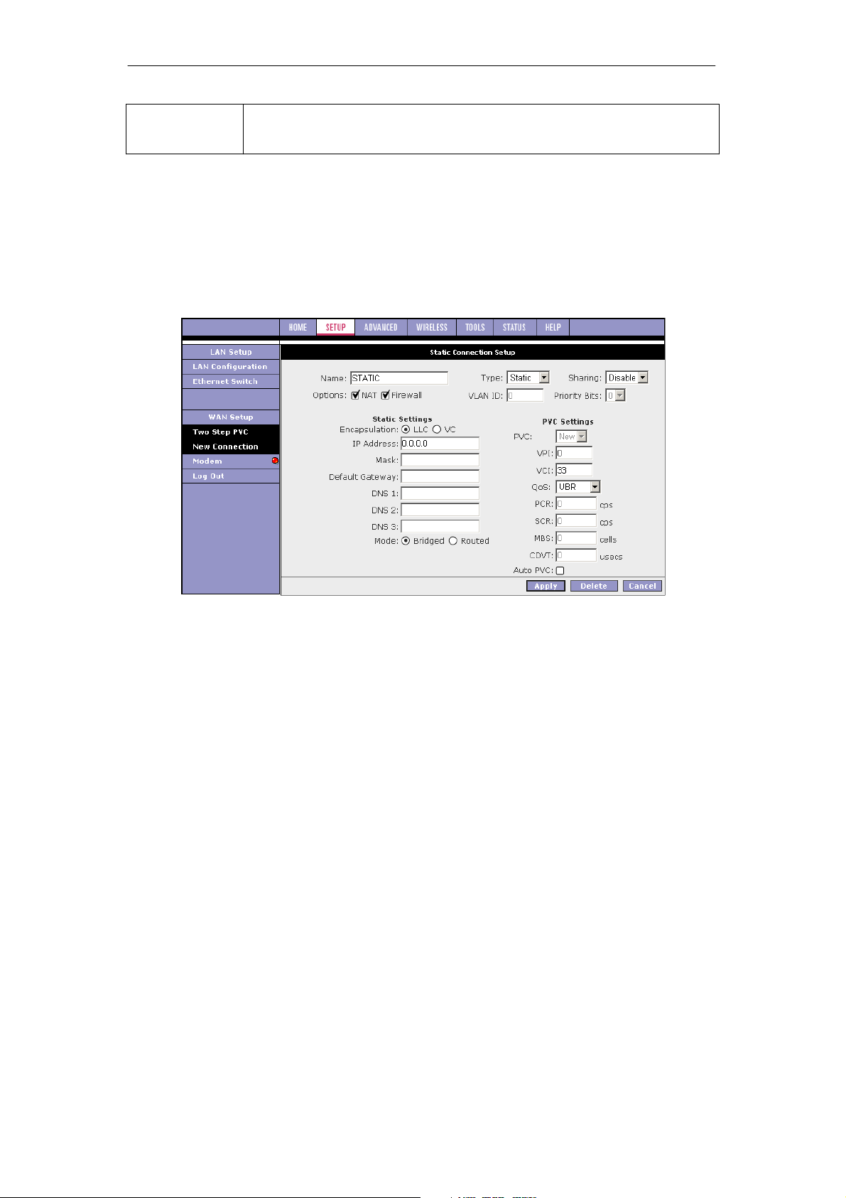
Static Connection Setup
Static connection type is used whenever a known static IP address is assigned to the
SOHOSpeed. Additional addressing information such as the subnet mask and the default
gateway must also be specified. Up to three domain name server (DNS) addresses can be
identified. These servers resolve the name of the computer to the IP address mapped to it
and thus enable you to access other web servers by typing the symbolic name (host name).
Enables PPPoA connection debugging facilities. This allows the ISP
technical support and ODM/OEM testers to simulate packets going through
from WAN side.
1. At the Setup main page, click New Connection.
The default PPPoE Connection Setup page is displayed.
2. At the Type field select Static.
The Static Connection Setup page is displayed.
3. In the Name field, enter a unique name for the Static connection.
The name must not have spaces and cannot begin with numbers. In this example, the
unique name is Static.
4. The Network Address Translation (NAT) and the Firewall options are enabled by
default. Leave these in the default mode.
5. In the Static Settings section, select the Encapsulation Type (LLC or VC).
Note: If you are not sure, just use the default mode.
6. Based upon the information your DSL/ISP provided, enter your assigned IP Address,
Subnet Mask, Default Gateway (if provided), and Domain Name Services (DNS)
values (if provided).
7. For the static configuration, you can also select a Bridged connection or a Routed
connection.
8. In the PVC Settings section, enter values for the VPI and VCI.
Note: Your DSL service provider or your ISP supplies these values. In this example, the
DSL service provider is using 0,33.
9. Select the Quality of Service (QoS). Leave the default value if you are unsure or if the
ISP did not provide this information.
The PCR, SCR, MBS, and CDVT fields are enabled/disabled depending on the QoS
selection. Enter the values provided by the ISP or leave the defaults.
10. Click Apply to complete the connection setup. This temporarily activates this connection.
A new link has been created for this connection in the left-hand column. You can apply,
delete, or cancel this connection using the buttons on this page.
19
Page 21
SOHOSpeed ADSL2/2+ Ethernet/Wireless Gateway User’s Manual
A new link is created for this connection in the left-hand column. You can connect,
disconnect, apply, delete, or cancel this connection using the buttons at the bottom of
this page.
Note: The changes take effect when you click Apply; however, if the SOHOSpeed
configuration is not saved, these changes will be lost upon SOHOSpeed reboot.
11. To make the change permanent, click Tools at the top of the page and select System
Commands.
12. At the System Commands page, click Save All.
13. To check the status, click Status at the top of the page and select Connection Status.
Field Description
Field
Encapsulation
IP Address
Mask
Gateway
Default
Gateway
DNS
Mode
Definition/Description
The technique used by layered protocols in which a layer adds header
information to the protocol data unit (PDU) from the layer above. As an
example, in Internet terminology, a packet would contain a header from the
data link layer, followed by a header from the network layer (IP), followed by a
header from the transport layer (TCP), followed by the application protocol
data. Two options are provided: Logical Link Control (LLC) and Virtual
Channel (VC).
IP address of the static connection provided by the ISP.
Subnet mask provided by your ISP.
The IP address of your gateway provided by the ISP.
The IP address of the default gateway to the Internet provided by the ISP.
Domain name server IP address provided by your ISP. You can configure up
to three DNS IP addresses.
Two modes are available: Bridged and Routed.
For VLAN and PVC field descriptions, please refer to section 3.4.1.
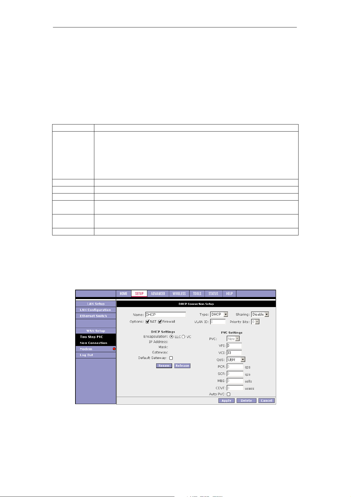
DHCP Connection Setup
DHCP allows the SOHOSpeed to automatically obtain the IP address from the server. This
option is commonly used in situations where the IP is dynamically assigned and is not known
prior to assignment.
1. On the Setup main page, click New Connection.
The default DHCP Connection Setup page is displayed.
2. From the Type drop-down box, select DHCP.
The default DHCP Connection Setup page is displayed.
20
Page 22

SOHOSpeed ADSL2/2+ Ethernet/Wireless Gateway User’s Manual
3. Enter a unique name for the DHCP connection in the Name field.
The name must not have spaces and cannot begin with numbers. In this example, the
unique name is DHCP.
4. The Network Address Translation (NAT) and the Firewall options are enabled by
default. Leave these in the default mode.
5. If your DSL line is connected and your DSL/IPS provider is supporting DHCP, you can
click Renew and the SOHOSpeed retrieves an IP Address, Subnet Mask, and Gateway
Address.
At any time, you can release the DHCP address by clicking Release, and renew the
DHCP address by clicking Renew.
6. Under PVC Settings, enter values for the VPI and VCI.
Note: Your DSL service provider or your ISP supplies these values. In this example, the
DSL service provider is using 0,35.
7. Select the Quality of Service (QoS). Leave the default value if you are unsure or if the
ISP did not provide this information.
The PCR, SCR, MBS, and CDVT fields are enabled/disabled depending on the QoS
selection. Enter the values provided by the ISP or leave the defaults.
8. Click Apply to complete the connection setup. This temporarily activates this connection.
A new link has been created for this connection in the left-hand column. You can apply,
delete, or cancel this connection using the buttons on this page.
Note: The changes take effect when you click Apply; however, if the SOHOSpeed
configuration is not saved, these changes will be lost upon SOHOSpeed reboot.
9. To make the change permanent, click Tools at the top of the page and select System
Commands.
10. At the System Commands page, click Save All.
11. To check the status, click Status at the top of the page and select Connection Status.
Field Description
Field Definition/Description
Encapsulation
IP Address
Mask
Gateway
Default Gateway
For VLAN and PVC field descriptions, please refer to section 3.4.1.
The technique used by layered protocols in which a layer adds header
information to the protocol data unit (PDU) from the layer above. As an
example, in Internet terminology, a packet would contain a header from the
data link layer, followed by a header from the network layer (IP), followed
by a header from the transport layer (TCP), followed by the application
protocol data. Two options are provided: Logical Link Control (LLC) and
Virtual Channel (VC).
IP address assigned by the DHCP server.
The subnet mask assigned by the DHCP server.
The IP address of your gateway.
If checked, this WAN connection acts as the default gateway to the
Internet.
21
Page 23
SOHOSpeed ADSL2/2+ Ethernet/Wireless Gateway User’s Manual
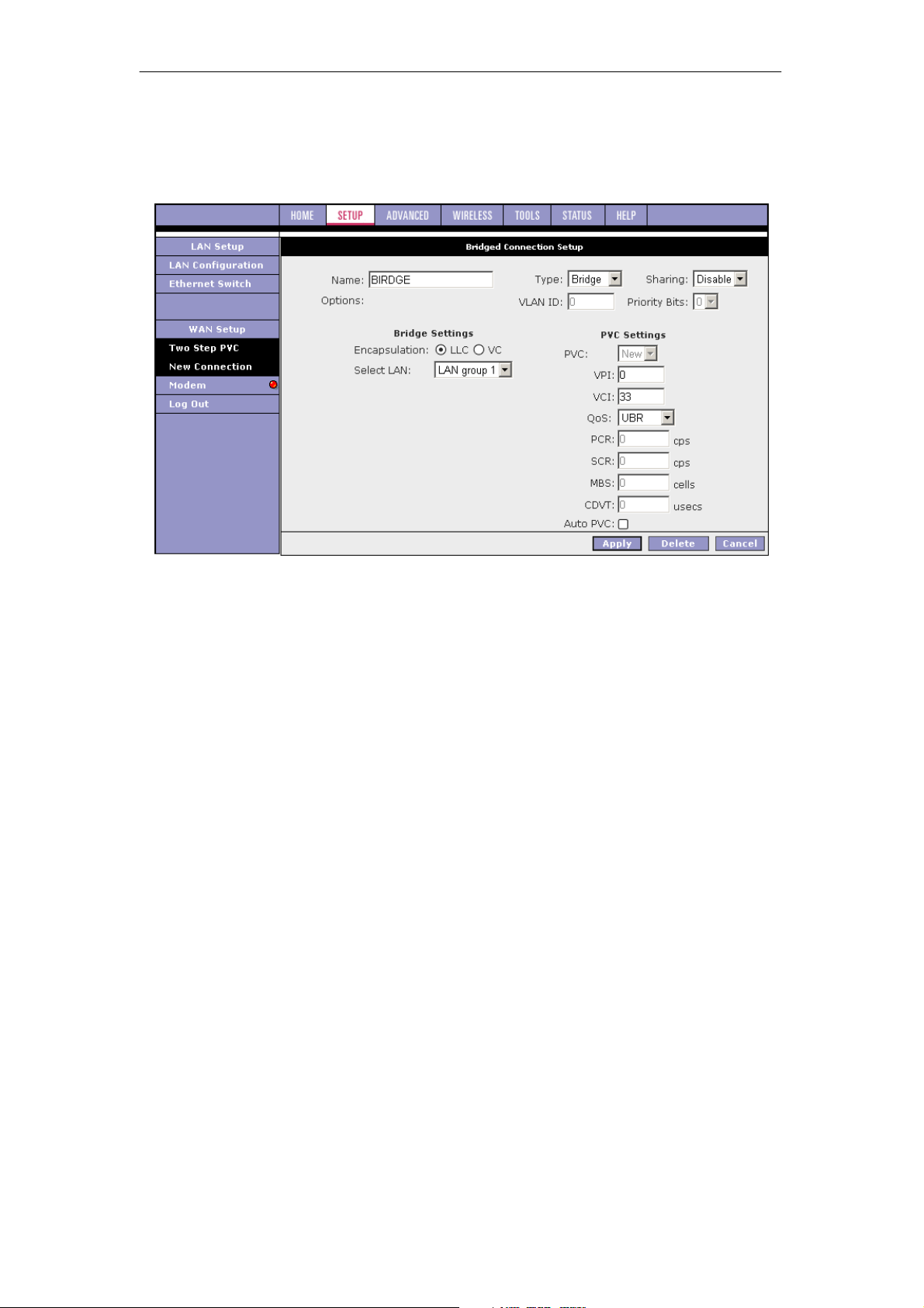
Bridged Profile and Connection
A pure bridged connection does not assign any IP address to the WAN interface. NAT and
firewall rules are not enabled. This connection method makes the SOHOSpeed act as a
bridge for passing packets between the WAN interface and the LAN interface.
1. On the Setup main page, click New Connection.
The default PPPoE Connection Setup page is displayed.
2. From Type drop-down box, select Bridge.
The default Bridged Connection Setup page is displayed.
3. Enter a unique name for the Bridged connection in the Name field.
The name must not have spaces and cannot begin with numbers. In this example, the
unique name is Bridge.
4. The Network Address Translation (NAT) and the Firewall options are enabled by
default. Leave these in the default mode.
5. In the Bridge Settings section, select the Encapsulation Type (LLC or VC).
Note: If you are not sure, just use the default mode.
6. In the PVC Settings section, enter values for the VPI and VCI.
Note: Your DSL service provider or your ISP supplies these values. In this example, the
DSL service provider is using 0,33.
7. Select the Quality of Service (QoS). Leave the default value if you are unsure or if the
ISP did not provide this information.
The PCR, SCR, MBS, and CDVT fields are enabled/disabled depending on the QoS
selection. Enter the values provided by the ISP or leave the defaults.
8. Click Apply to complete the connection setup. This temporarily activates this connection.
A new link has been created for this connection in the left-hand column. You can apply,
delete, or cancel this connection using this page.
Note: The changes take effect when you click Apply; however, if the SOHOSpeed
configuration is not saved, these changes will be lost upon SOHOSpeed reboot.
9. To make the change permanent, click Tools at the top of the page and select System
Commands.
10. At the System Commands page, click Save All.
11. To check the status, click Status and select Connection Status.
22
Page 24
SOHOSpeed ADSL2/2+ Ethernet/Wireless Gateway User’s Manual
Field Description
Field
Encapsulation
Select LAN
For VLAN and PVC field descriptions, please refer to section 3.4.1.
Definition/Description
The technique used by layered protocols in which a layer adds header
information to the protocol data unit (PDU) from the layer above. As an
example, in Internet terminology, a packet would contain a header from the
data link layer, followed by a header from the network layer (IP), followed by
a header from the transport layer (TCP), followed by the application protocol
data. Two encapsulation options are provided:
z Logical Link Control (LLC)
z Virtual Channel (VC)
Select the LAN group for the bridged connection. The following options are
available:
z LAN Group 1
z LAN Group 2
z LAN Group 3
z None
This bridged connection will be added to the selected LAN group. If you
select None, the connection is not added to any LAN group but to the
Interfaces box on the LAN Configuration page, which can be configured to
a LAN group on the same page.
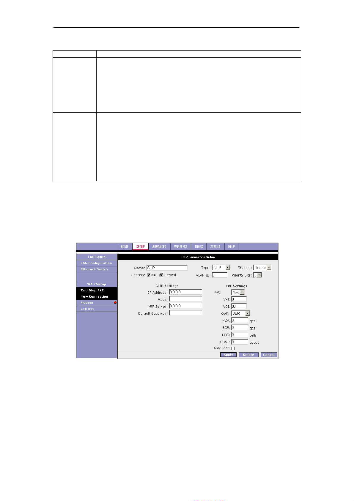
Classical IP over ATM Connection Setup
CLIP, defined in RFC 2225, provides the ability to transmit IP packets over an ATM network.
This SOHOSpeed’s CLIP support encapsulates an IP datagram in an AAL5 PDU frame using
RFC 2225 and it uses an ATM-aware version of the address resolution protocol (ATMARP).
Its CLIP support only allows support for PVCs, SVCs are not supported by the SOHOSpeed.
1. On the Setup main page, click New Connection.
The default PPPoE Connection Setup page is displayed.
2. From Type drop-down box, select CLIP.
The default CLIP Connection Setup page is displayed.
3. Enter a unique name for the static connection in the Name field.
The name must not have spaces and cannot begin with numbers. In this example, the
unique name is Clip.
4. The Network Address Translation (NAT) and the Firewall options are enabled by
default. Leave these in the default mode.
5. Based upon the information your DSL/ISP provided, enter your assigned IP Address,
Mask, ARP Server, and Default Gateway.
23
Page 25

SOHOSpeed ADSL2/2+ Ethernet/Wireless Gateway User’s Manual
6. In the PVC Settings section, enter values for the VPI and VCI.
Note: Your DSL service provider or your ISP supplies these values.
7. Select the Quality of Service (QoS); leave the default value if you are unsure or if the
ISP did not provide this information.
The PCR, SCR, MBS, and CDVT fields are enabled/disabled depending on the QoS
selection. Enter the values provided by the ISP or leave the defaults.
8. Click Apply to complete the connection setup. This temporarily activates this connection.
A new link has been created for this connection in the left-hand column. You can apply,
delete, or cancel this connection using this page.
Note: The changes take effect when you click Apply; however, if the SOHOSpeed
configuration is not saved, these changes will be lost upon SOHOSpeed reboot.
9. To make the change permanent, click Tools at the top of the page and select System
Commands.
10. At the System Commands page, click Save All.
11. To check the status, click Status at the top of the page and select Connection Status.
Field Description
Field
IP Address
Mask
ARP Server
Default Gateway
Definition/Description
IP address of the CLIP connection provided by your ISP.
Subnet mask provided by your ISP.
IP address of the Address Resolution Protocol (ARP) server provided by
your ISP.
If checked, this WAN connection acts as the default gateway to the
Internet.
For VLAN and PVC field descriptions, please refer to section 3.4.1.
3.4.2 Tow Step PVC
The Two-step PVC page is added to support the Remote Management /Clear Embedded
Operations Channel (EOC) feature, which is a China MII requirement. This page allows WAN
connections to be created in two steps:
1. Create multiple PVCs with VPI, VCI values, and encapsulation types. The following
encapsulation methods are supported:
z PPPoA
z PPPoE
z Router 1483
z Bridge
z Static
z DHCP
z CLIP
24
Page 26
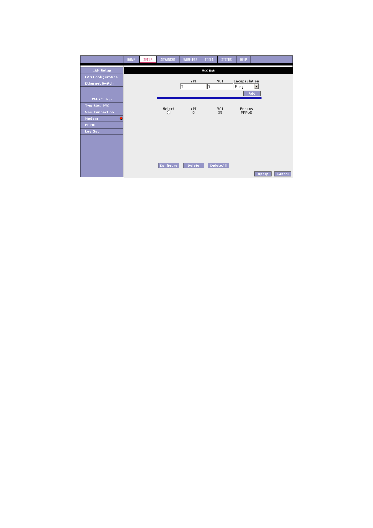
SOHOSpeed ADSL2/2+ Ethernet/Wireless Gateway User’s Manual
2. Create a WAN connection from an existing PVC.
For more information about VPI and VCI, refer to the table in section 3.4.11.
3.4.3 Modify an Existing Connection
1. On the Setup main page, select the connection you want to modify from the left-hand
column.
The connections are listed as Connection 1 through Connection 8.
Note: Up to eight WAN connections of all types are supported.
2. Make modifications on the individual connection page.
Note: Some fields are disabled after initial creation.
3. Click Apply to temporarily activate the changes you made.
Note: The changes take effect when you click Apply; however, if the SOHOSpeed
configuration is not saved, these changes will be lost upon SOHOSpeed reboot.
4. To make the change permanent, click Tools at the top of the page and select System
Commands.
5. At the System Commands page, click Save All.
25
Page 27
SOHOSpeed ADSL2/2+ Ethernet/Wireless Gateway User’s Manual
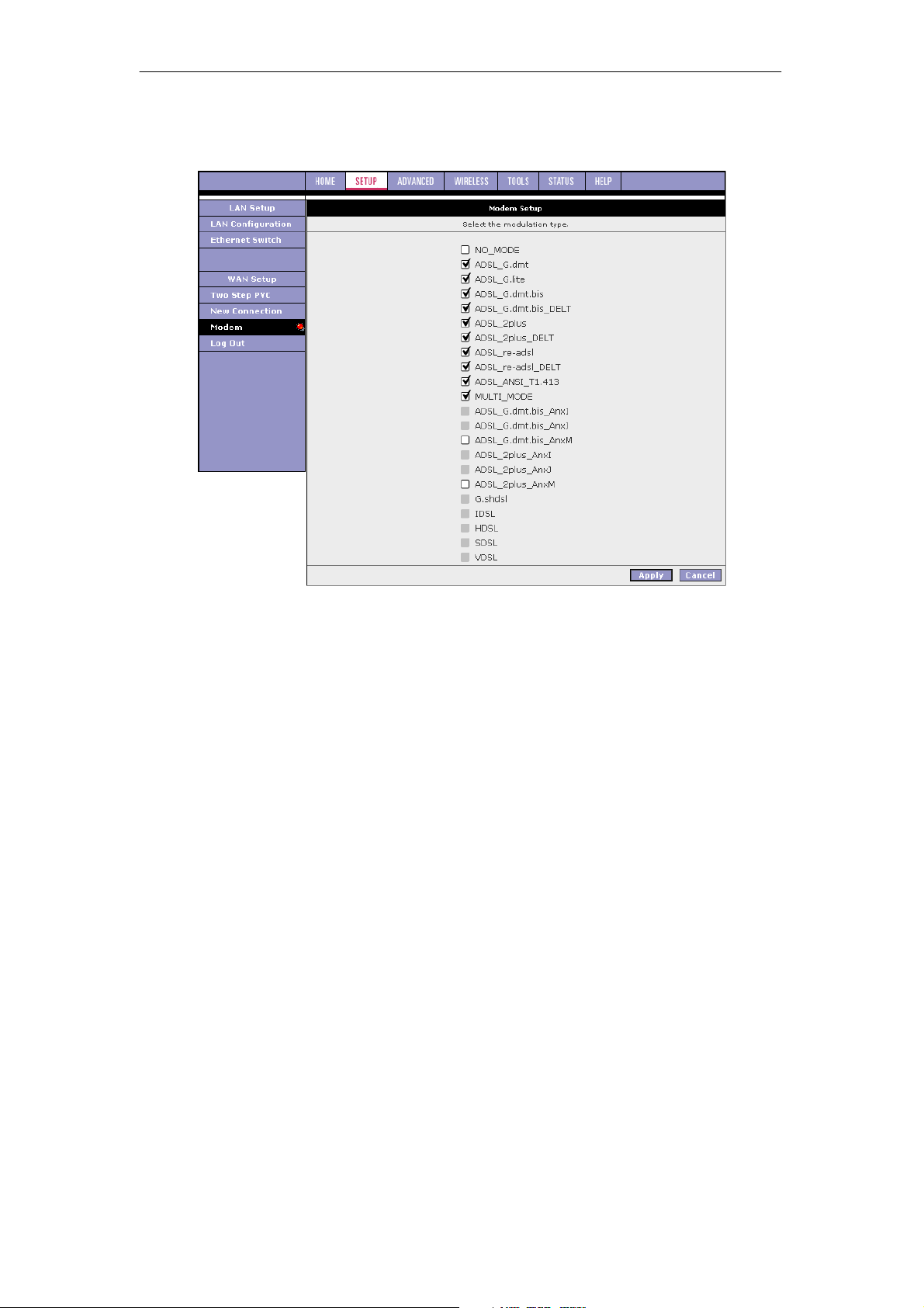
3.4.4 Modem Setup
The Modem Setup page allows you to select any combination of DSL training modes.
26
Page 28
SOHOSpeed ADSL2/2+ Ethernet/Wireless Gateway User’s Manual
3.5 Configuring the LAN
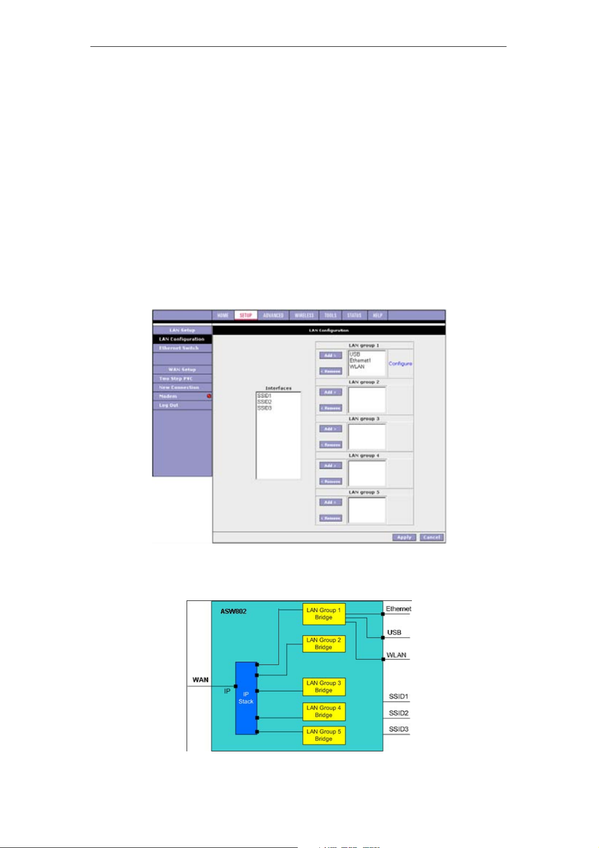
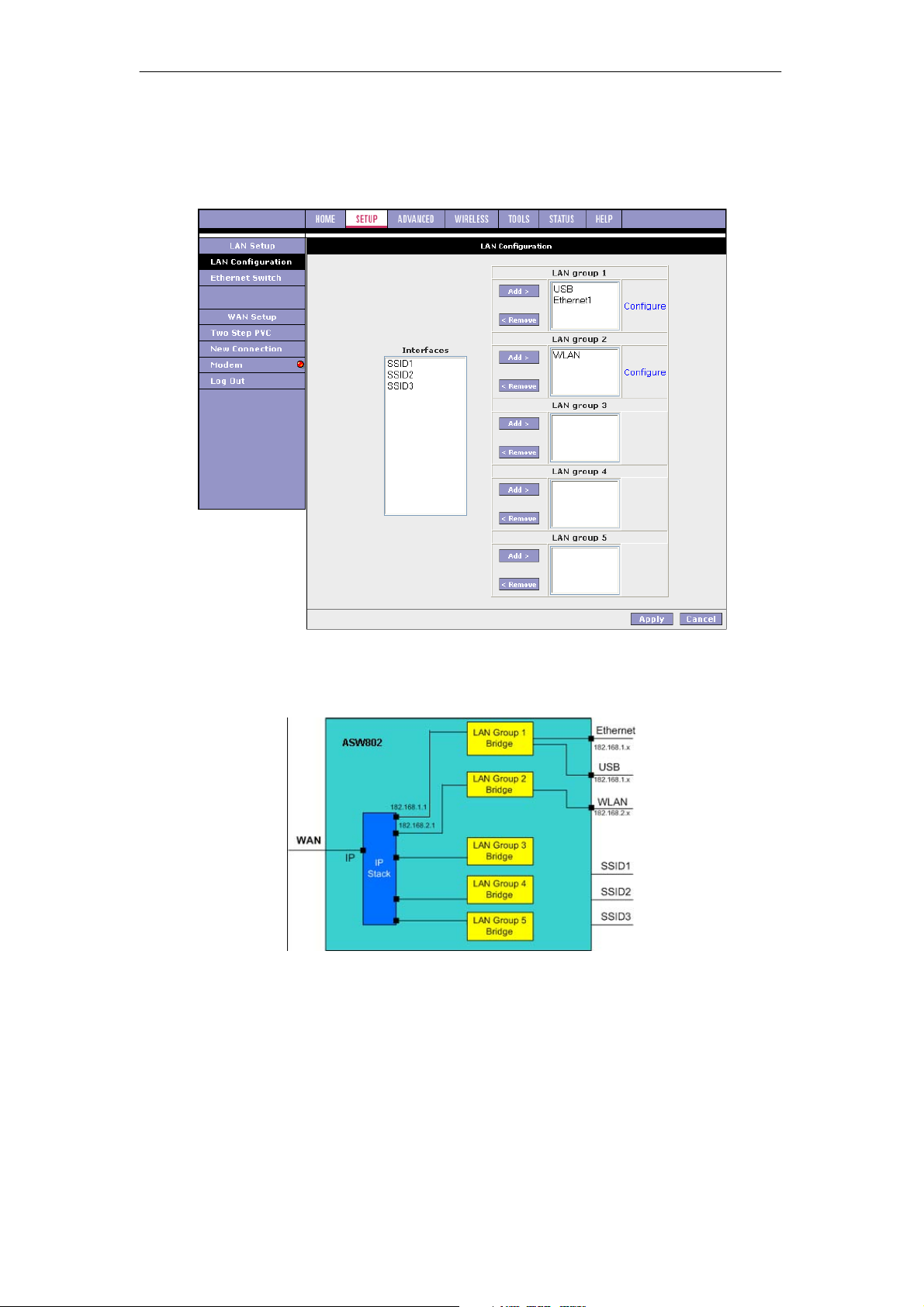
The SOHOSpeed provides LAN configuration for multiple LAN bridge groups. Up to five LAN
bridge groups are supported. The LAN interefaces could include: Ethernet, USB, WLAN
(Primary SSID), SSID1, SSID2, and SSID3. It is possible to assign any LAN interface to any
bridge group but only one group, except that the Ethernet interface needs to stay in LAN
group 1. Each LAN group can then be configured with static IP address, dynamic IP address,
or be unmanaged (no IP).
The default LAN Configuration page shows the LAN interfaces that belong to a single LAN
bridge group (LAN Group 1):
z USB
z Ethernet
z WLAN
Note: The following interfaces are not valid until multiple SSID is enabled and the secondary
SSIDs are configured:
z SSID1 (corresponds to the first secondary SSID)
z SSID2 (corresponds to the second secondary SSID)
z SSID3 (corresponds to the third secondary SSID)
For more information on how to configure multiple SSIDs, refer to ‘‘Multiple SSID’’.
The SOHOSpeed performs routing between the LAN group 1 and the WAN connections as
shown in figure below.
27
Page 29
SOHOSpeed ADSL2/2+ Ethernet/Wireless Gateway User’s Manual
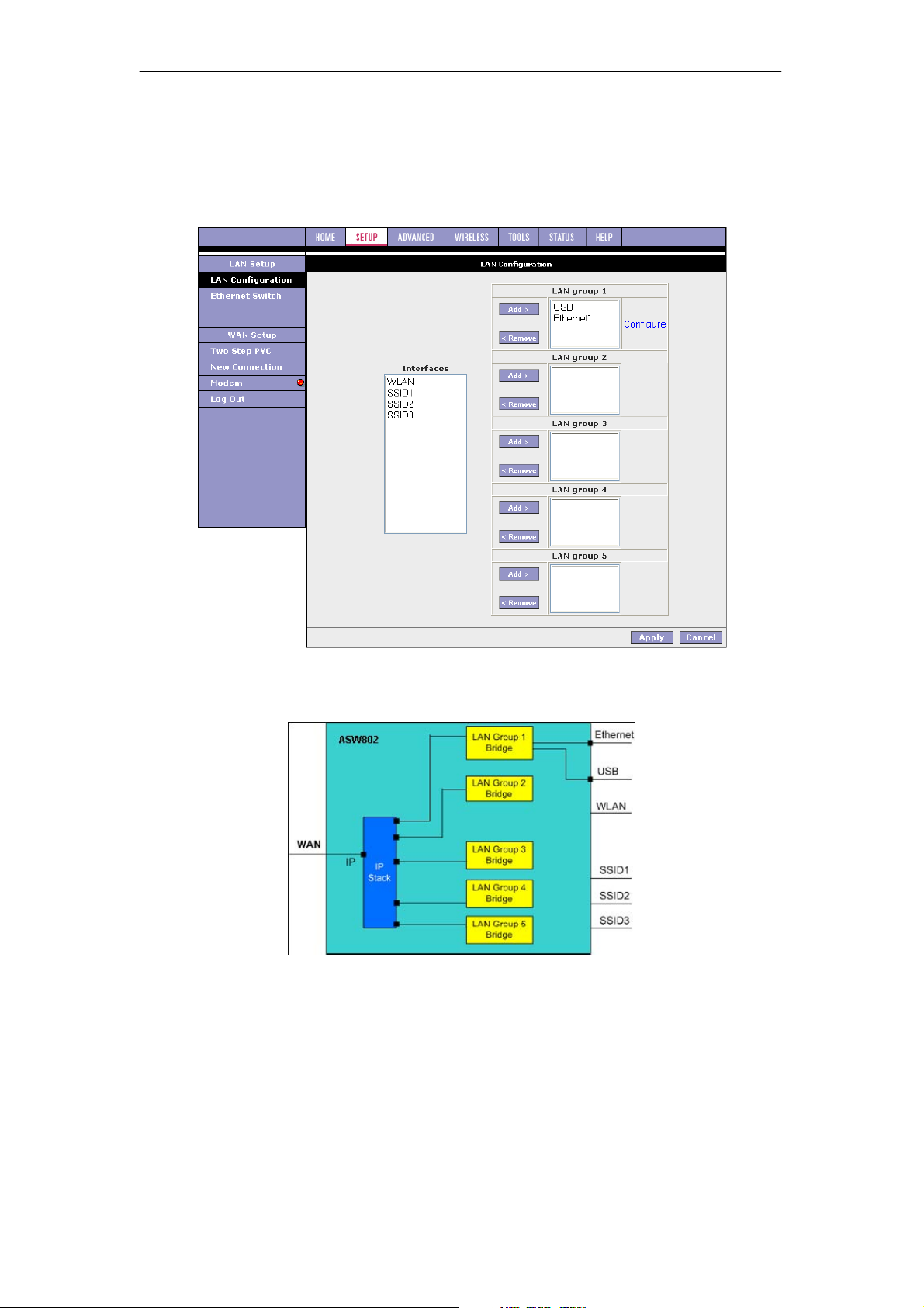
Follow the procedure below to configure LAN group 2.
1. Select WLAN interface in LAN group 1 and click Remove.
WLAN moves to the Interfaces box on the left as shown in figure below.
Note: You can configure the USB interface and WLAN interfaces to a different LAN
group; however, the Ethernet interface is default in LAN group 1 and cannot be moved.
No packets are sent to the WLAN interface as it does not belong to any LAN group. This
is shown in figure below.
28
Page 30
SOHOSpeed ADSL2/2+ Ethernet/Wireless Gateway User’s Manual
2. Select WLAN in the Interface box and click Add next to LAN group 2.
WLAN moves to LAN group 2 as shown in figure below. The Configure link for LAN
group 2 has also been generated, allowing additional configurations for the defined LAN
group.
Two LAN segments have been configured as shown in figure below with two sets of IP
addresses. The Ethernet and USB interfaces belong to LAN group 1 with an IP of 192.168.1.x.
The WLAN interface belongs to LAN group 2 with an IP of 192.168.2.x.
3. Click Apply to temporarily activate the changes.
Note: The changes take effect when you click Apply; however, if the SOHOSpeed
configuration is not saved, these changes will be lost upon SOHOSpeed reboot.
4. To make the change permanent, click Tools at the top of the page and select System
Commands.
5. At the System Commands page, click Save All.
29
Page 31
SOHOSpeed ADSL2/2+ Ethernet/Wireless Gateway User’s Manual
3.5.1 LAN Group Configuration
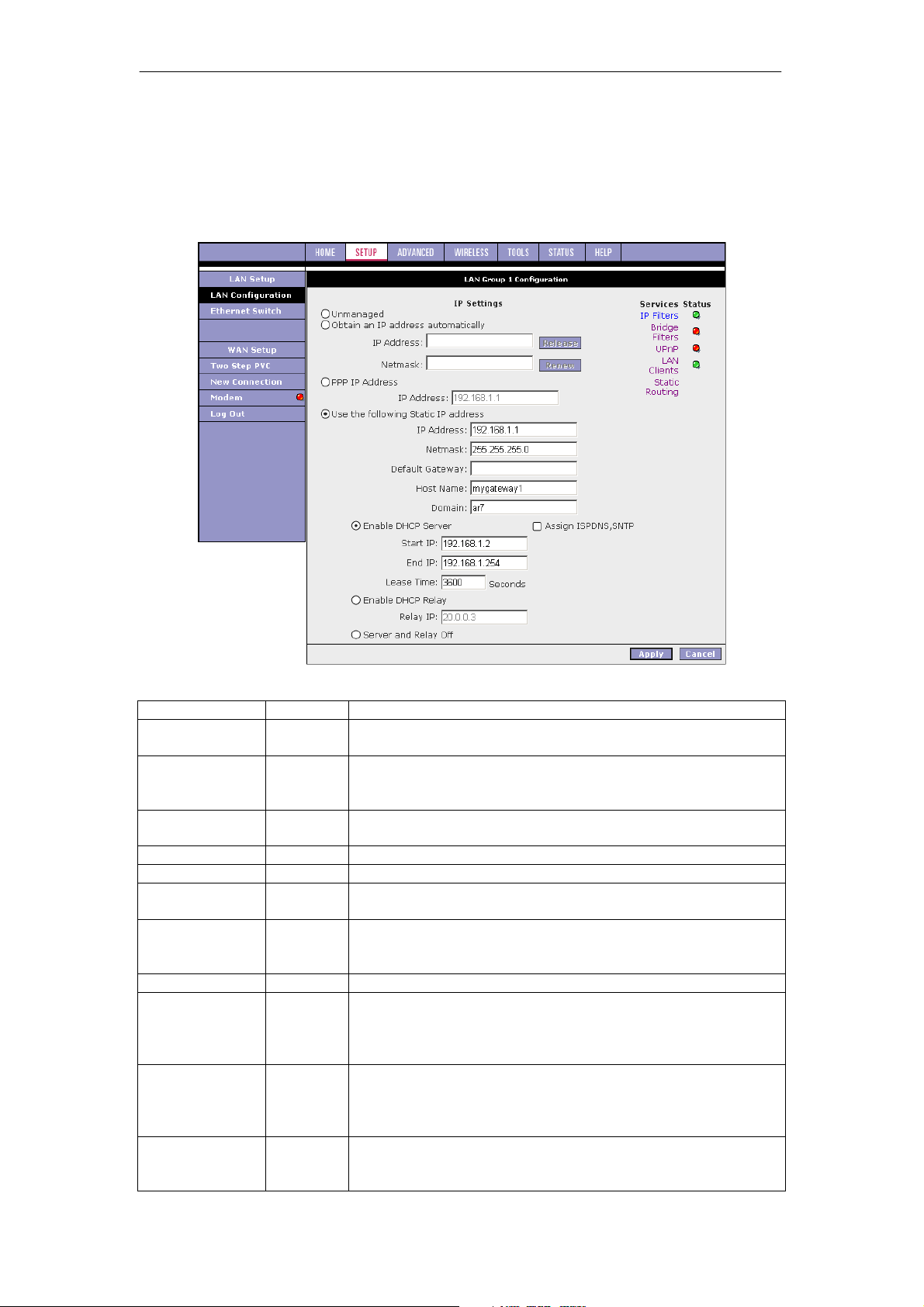
The LAN Group Configuration page allows you to configure settings for each defined LAN
group.
Notice that you can also view the status of advanced services that can be applied to this LAN
group. A green status indicates that the services have been enabled, while a red status
indicates that the service is currently disabled.
Field Description
Category/Field
Unmanaged
Obtain an IP
address
automatically
PPP IP Address
Use the
following Static
IP address
Field Definition/Description
Unmanaged is a state when the LAN group is not configured
and no IP address has been assigned to the bridge.
When this function is enabled, your SOHOSpeed acts like a
client and requests an IP address from the DHCP server on
the LAN side.
IP Address You can retrieve/renew an IP address from the DHCP server
using the Release and Renew buttons.
Netmask The subnet mask of your Gateway.
Enables/disables PPP unnumbered feature.
IP Address The IP address should be different from, but in the same
subnet as the WAN-side IP address.
This field enables you to change the IP address of the
SOHOSpeed.
IP Address The default IP address of the SOHOSpeed is 192.168.1.1.
Netmask The default subnet mask of your SOHOSpeed is
255.255.255.0. This subnet allows the SOHOSpeed to support
254 users. If you want to support a larger number of users you
can change the subnet mask.
Default
Gateway
Host Name The host name is used in conjunction with the domain name to
The default gateway is the routing device used to forward all
traffic that is not addressed to a station within the local subnet.
Your ISP provides you with the IP address of the default
gateway.
uniquely identify the SOHOSpeed. It can be any alphanumeric
word that does not contain spaces.
30
Page 32

Enable DHCP
Server
Enable DHCP
Relay
Server and
Relay Off
SOHOSpeed ADSL2/2+ Ethernet/Wireless Gateway User’s Manual
Domain The domain name is used in conjunction with the host
name to uniquely identify the SOHOSpeed. To access the web
pages of the SOHOSpeed you can type 192.168.1.1 (the IP
address) or mygateway1.ar7 (Host Name.Domain).
Enables/disables DHCP. By default, your SOHOSpeed has the
DHCP server (LAN side) enabled. If you already have a DHCP
server running on your network, you must disable one of the
two DHCP servers.
Assign ISP
DNS,
SNTP
Enable/disables the Assign ISP DNS, SNTP feature when the
DHCP server of your SOHOSpeed has been enabled. To learn
more about the Assign ISP DNS, SNTP feature, refer to
‘‘Assign ISP DNS, SNTP’’.
Start IP The Start IP Address is where the DHCP server starts issuing
IP addresses. This value must be greater than the IP address
value of the SOHOSpeed. For example, if the IP address of
the SOHOSpeed is 192.168.1.1 (default), then the starting IP
address must be 192.168.1.2 (or higher).
Note: If you change the start or end values, make sure the
values are still within the same subnet as the SOHOSpeed. In
other words, if the IP address of the SOHOSpeed is
192.168.1.1 (default) and you change the DHCP start/end IP
addresses to be 192.168.1.2/192.168.1.100, you cannot
communicate with the SOHOSpeed if your host has DHCP
enabled.
End IP The End IP Address is where the DHCP server stops issuing
IP addresses. The ending address cannot exceed a subnet
limit of 254, hence the max value for the default gateway is
192.168.1.254. If the DHCP server runs out of DHCP
addresses, users do not get access to network resources. If
this happens, you can increase the Ending IP address (to the
limit of 254) or reduce the lease time.
Note: If you change the start or end values, make sure the
values are still within the same subnet as the IP address of the
SOHOSpeed. In other words, if the IP address of the
SOHOSpeed is 192.168.1.1 (default) and you change the
DHCP start/end IP addresses to be
192.168.1.2/192.168.1.100, you cannot communicate with the
SOHOSpeed if your host has DHCP enabled.
Lease
Time
The Lease Time is the amount of time that a network user is
allowed to maintain a network connection to the SOHOSpeed
using the current dynamic IP address. At the end of the Lease
Time, the lease is either renewed or a new IP is issued by the
DHCP server. The amount of time is in units of seconds. The
default value is 3600 seconds (1 hour). The maximum value is
999999 seconds (about 278 hours).
In addition to the DHCP server feature, the SOHOSpeed
supports the DHCP relay function. When the SOHOSpeed is
configured as DHCP server, it assigns the IP addresses to the
LAN clients. When the SOHOSpeed is configured as DHCP
relay, it is responsible for forwarding the requests and
responses negotiated between the DHCP clients and the
server.
Relay IP The IP address of the DHCP relay server.
When the DHCP server and relay functions are turned off, the
network administrator must carefully configure the IP address,
Subnet Mask, and DNS settings of every host on your network.
Do not assign the same IP address to more than one host.
Also, your SOHOSpeed must reside on the same subnet as all
the other hosts.
31
Page 33
SOHOSpeed ADSL2/2+ Ethernet/Wireless Gateway User’s Manual
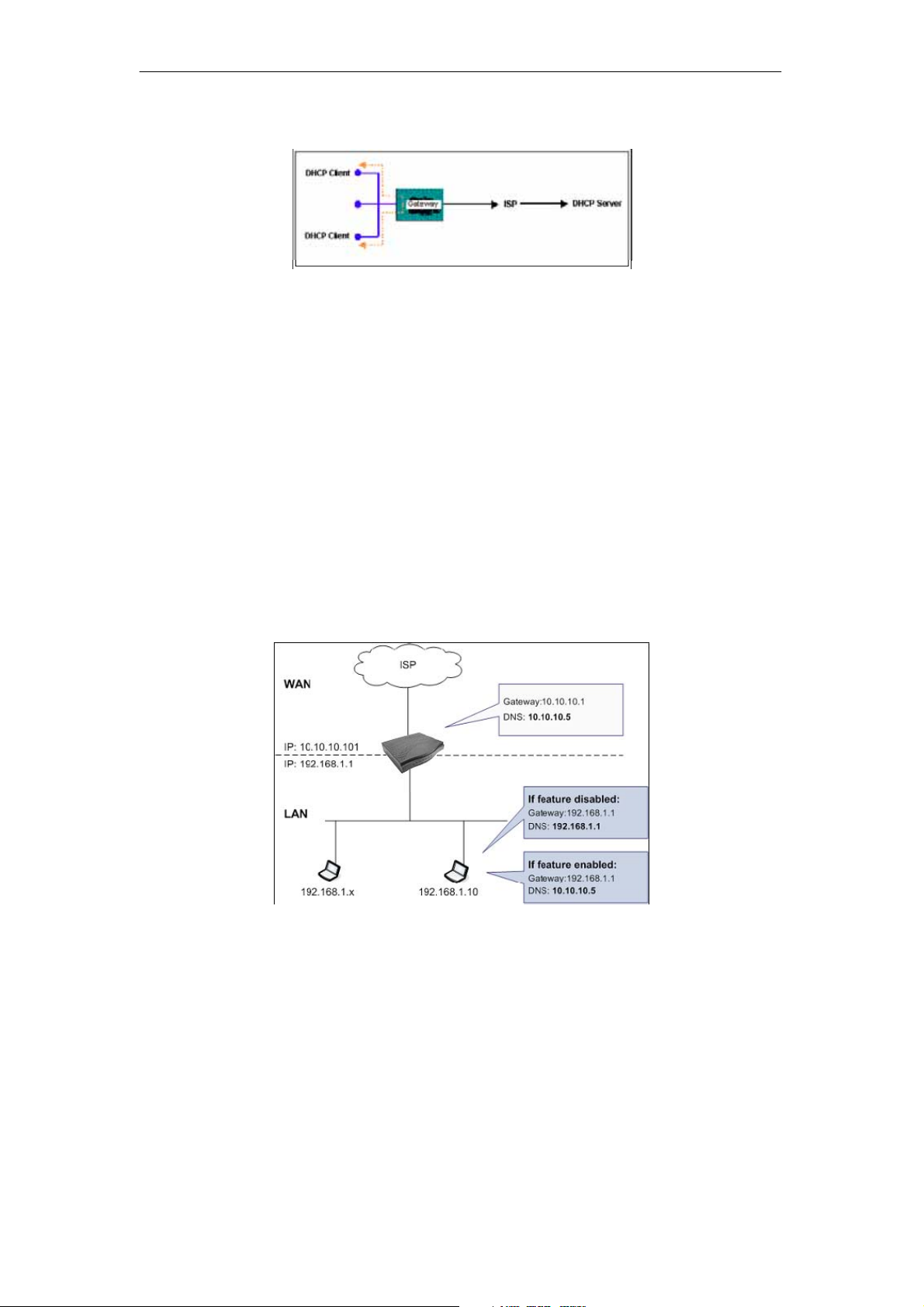
Example of a DHCP Relay configuration
4.6.1.1 Assign ISP DNS, SNTP
When you enable the DHCP server on the LAN side, the SOHOSpeed dynamically assigns IP
addresses to the hosts on the local network. The SOHOSpeed provides its own LAN IP
address (192.168.1.1) as both the gateway and the DNS server.
On the WAN side, the SOHOSpeed receives the following data (among other data) from the
ISP:
z IP: 10.10.10.101
z Gateway: 10.10.10.1
z DNS: 10.10.10.5
The SOHOSpeed has a choice of advertising its own IP address (192.168.1.1) to the LAN
side hosts as the DNS server, or providing the DNS that was received from the WAN side
(10.10.10.5). This can be configured by enabling/ disabling Assign ISP DNS SNTP on the
LAN Group Configuration page.
Note: This section only applies when you have enabled DHCP server on the LAN Group
Configuration page.
External DHCP Options
The default option (feature disabled)
As shown in figure above, when Assign ISP DSN SNTP is disabled, the hosts on the LAN
network use the LAN IP address of the SOHOSpeed as the DNS. The following data is
provided to the host by the DHCP server.
z IP: 192.168.1.x
z Gateway: 192.168.1.1
z DNS: 192.168.1.1
The external DHCP option (feature enabled)
As shown in figure above, when Assign ISP DSN SNTP is enabled, the host on the LAN
network uses the WAN side DNS. The following data is provided to the host:
z IP: 192.168.1.x
z Gateway: 192.168.1.1
z DNS: 10.0.0.5
32
Page 34
SOHOSpeed ADSL2/2+ Ethernet/Wireless Gateway User’s Manual
Note: If the WAN connection is also of DHCP type, the SOHOSpeed receives additional data
from the ISP, and if Assign ISP DSN SNTP is enabled, the data is passed on to the LAN side
hosts as well. The additional data may include (but not limited to) the following:
z Time server
z Log server
z Cookie server
z Print server
z NTP server
z WINS server
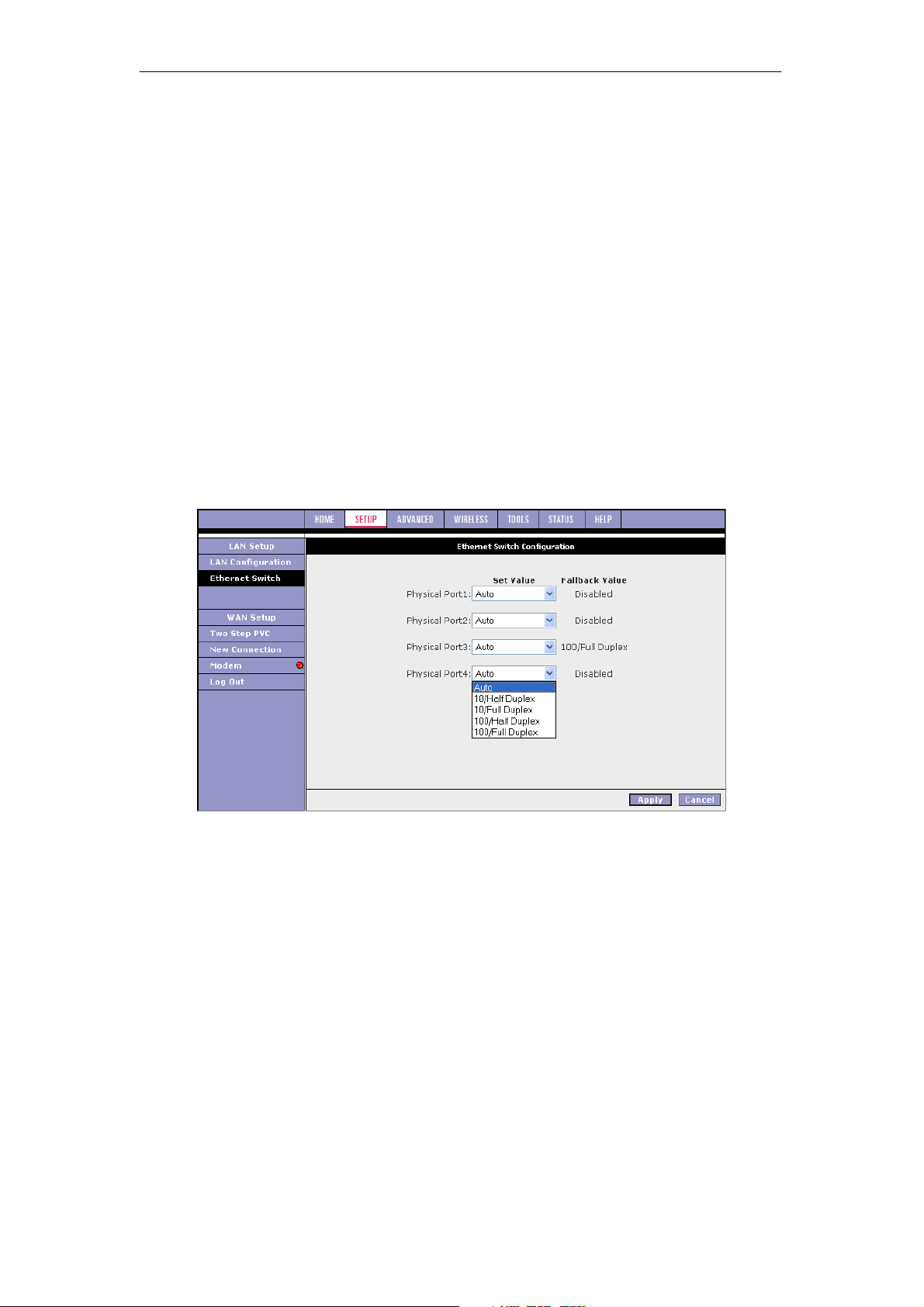
3.5.2 Ethernet Switch Configuration
Ethernet switch port settings can be configured to meet the requirements of your LAN
configuration. As seen in the drop-down menu in figure below, port setting options include:
z Auto detect (default)
z 10 Mbps half duplex
z 10 Mbps full duplex
z 100 Mbps half duplex
z 100 Mbps full duplex
In the example shown, the system has auto-detected an Ethernet cable connected to LAN
port 3 and assigned a port setting of 100 Mbps full duplex.
33
Page 35
SOHOSpeed ADSL2/2+ Ethernet/Wireless Gateway User’s Manual
3.6 Configuring the WLAN
The wireless local area networks (WLAN) tab allows you to perform WLAN interface
configuration functions.
3.6.1 WIRELESS Setup
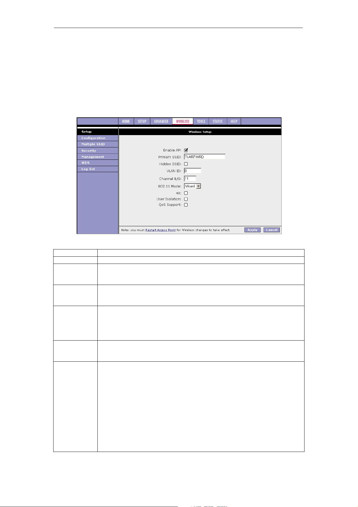
The default Wireless Setup page which is accessed by clicking the Setup link. This page
provides basic access point (AP) parameter settings.
Note: you must Restart Access Point for Wireless changes to take effect.
Field Description
Field Definition/Description
Enable AP
Primary SSID
Hidden SSID
VLAN ID
Channel B/G
802.11 Mode
Enables/disables the access point.
The primary service set identifier of the AP, which is the only SSID your AP
broadcasts (if hidden SSID is disabled). The default is TI-AR7WRD and you
can assign a unique SSID to your AP. The SSID is up to 32 characters.
Enables/disables the hidden SSID feature. When hidden SSID is enabled,
the SSID is removed from the beacon frames the AP transmits, thus the AP
will not be seen by any other station.
The VLAN ID for the primary SSID. By default, multiple SSID is disabled and
the VLAN ID of the primary SSID is 0. When you enable multiple SSID, you
are prompted to change the VLAN ID of the primary SSID to a unique value
between 1 - 4095. For more information on enabling multiple SSID, refer to
‘‘Multiple SSID’’.
The channel on which the AP and the wireless stations communicate.
Different domains have different ranges of channels. For FCC in 2.4 GHz,
the default channel is 11.
You can select from the following modes:
z Mixed mode: Both 802.11b and g modes are supported. The legacy
supported rates information element (SR IE) contains the 802.11b
legacy supported rates and the additional OFDM supported rates.
Extended SR IE contains the extended supported rates, if present.
Beacon & Probe Response Frames are sent in b rate.
z 11b only Mode: The legacy SR IE contains only the 802.11b legacy
supported rates. The extended SR IE is not present.
z 11b+ Mode: Similar to the 802.11b-only mode except that 22Mbps
PBCC rate/modulation is included, which is TI proprietary.
z 11g only Mode: The legacy SR IE contains only the OFDM additional
supported rates. The extended SR IE contains the extended supported
rates, if present.
34
Page 36
SOHOSpeed ADSL2/2+ Ethernet/Wireless Gateway User’s Manual
4X
User Isolation
QoS
User Isolation
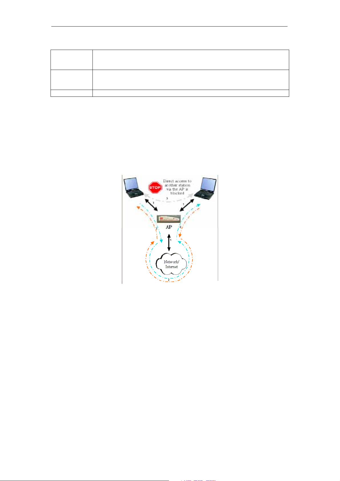
When user isolation is enabled, wireless users will not be able to directly access other
wireless users. Access can be controlled by the AP.
The figure below illustrates the three states of enabling the user isolation feature:
Enables/disables the 4x feature for 802.11g mode. This function is
SOHOSpeed proprietary and is only available when both TI wireless station
card and SOHOSpeed are used.
When checked, wireless users will not be able to directly access other
wireless users. More details on User Isolation are discussed in ‘‘User
Isolation’’.
Support Refer to ‘‘WLAN QoS Support’’ for more information.
1. AP disabled basic service set (BSS) bridging: Before user isolation is enabled, the
stations can exchange data via the AP. This is disabled when user isolation is enabled.
2. All data is sent to WAN.
3. Enable/disable flag: No station has direct access to other stations as a result of user
isolation.
Follow the procedure below to save changes you have made on the Wireless Setup page.
1. Click Apply.
2. Click Restart Access Point at the bottom of the page, which takes you to the System
Commands page.
Note: An alternative way to access the System Commands page is to select Tools at
the top of the page, then click the System Commands link.
3. On the System Commands page, click Save All.
This temporarily saves all the changes you have made. You will still need to restart the
access point for any changes to take effect.
4. Click Restart Access Point for changes to the WLAN settings to take effect.
CAUTION: Any changes you make to the WLAN page do NOT get saved automatically.
Clicking Apply on the individual page is not sufficient for the changes you made to take effect.
For changes you made to any WLAN page to take effect, you must perform the steps as
described above.
35
Page 37
62+26SHHG$'6/(WKHUQHW:LUHOHVV*DWHZD\8VHU¶V0DQXDO
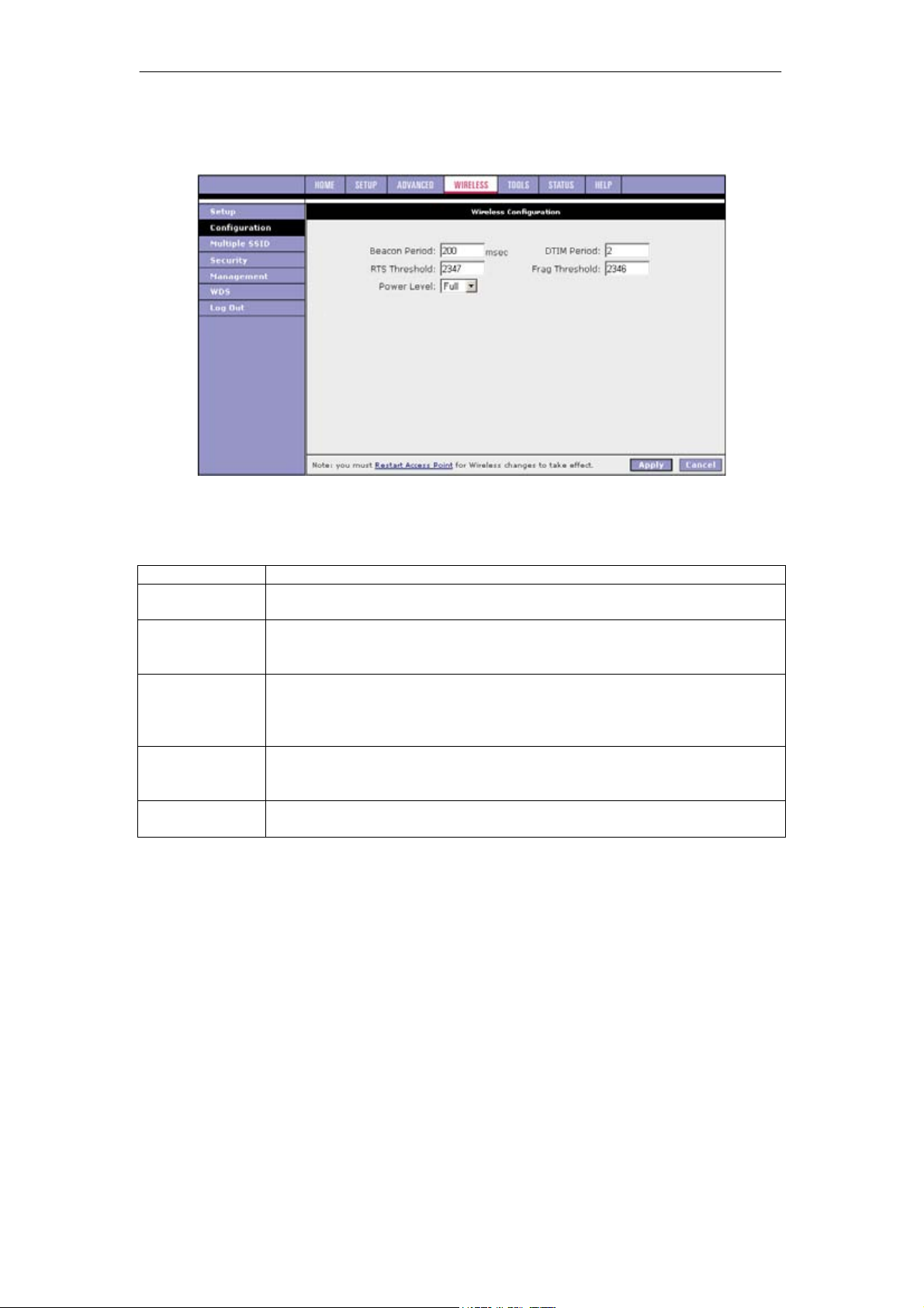
:LUHOHVV&RQILJXUDWLRQ
7KLVSDJHSURYLGHVWKHDGYDQFHGZLUHOHVVQHWZRUNSDUDPHWHUVHWWLQJV
1RWH7KHKLJKOLJKWHGDUHDUHODWHVWRWKHPXOWLGRPDLQFDSDELOLW\IXQFWLRQZKLFKFDQQRWEH
FRQILJXUHGE\WKHHQGXVHULVDQUHVHUYHGIXQFWLRQ
)LHOG'HVFULSWLRQ
LWLRQ'HVFULSWLRQ
)LHOG
%HDFRQ3HULRG
'7,0SHULRG
576WKUHVKROG
)UDJPHQWDWLRQ
3RZHU/HYHO
)ROORZWKHSURFHGXUHEHORZWRVDYHFKDQJHV\RXKDYHPDGHRQWKH:LUHOHVV6HWXSSDJH
'HILQ
WLPHLQWHUYDOEHWZHHQEHDFRQIUDPHWUDQVPLVVLRQVZKLFKUDQJHVIURP
7KH
PVHF7KHGHIDXOWYDOXHRIWKLVILHOGLVPVHF
'HOLYHU\WUDIILFLGHQWLILFDWLRQPDSSHULRG7KHQXPEHURIEHDFRQIUDPH
WUDQVPLVVLRQVEHIRUHIUDPHVWKDWDUHWDUJHWHGIRUVWDWLRQVRSHUDWLQJLQORZ
SRZHUPRGHZLOOEHWUDQVPLWWHG7KHGHIDXOWYDOXHRIWKLVILHOGLV
5HTXHVWWRVHQGWKUHVKROG7KHQXPEHURIE\WHVLQD0DFSURWRFROGDWD
XQLW03'8EHORZZKLFKDQ576&76KDQGVKDNHZLOOQRWEHSHUIRUPHG
7KHGHIDXOWYDOXHLVKRZHYHUZKHQ[LVHQDEOHGRQWKHVHWXSSDJH
WKH576WKUHVKROGYDOXHFKDQJHVWR
7KUHVKROG7KHPLQLPXPOHQJWKRIDIUDPHWKDWZLOOEHIUDJPHQWHG7KH
GHIDXOW
YDOXHLVKRZHYHUZKHQ[LVHQDEOHGRQWKH6HWXSSDJHWKH
IUDJPHQWDWLRQWKUHVKROGYDOXHFKDQJHVWR
7KH7[RXWSXWSRZHUSHUFHQWDJHFRPSDUHGWRWKHPD[LPXP7[SRZHUIXOO
DQG'HIDXOWLV)XOOSRZHU
&OLFN $SSO\
&OLFN 5HVWDUW$FFHVV3RLQWDWWKHERWWRPRIWKHSDJHZKLFKWDNHV\RXWRWKH6\VWHP
&RPPDQGVSDJH
1RWH$QDOWHUQDWLYHZD\WRDFFHVVWKH6\VWHP&RPPDQGVSDJHLVWRVHOHFW7RROVDW
WKH
WRSRIWKHSDJHWKHQFOLFNWKH6\VWHP&RPPDQGVOLQN
2QWKH6\VWHP&RPPDQGVSDJHFOLFN6DYH$OO
7KLVWHPSRUDULO\VDYHVDOOWKHFKDQJHV\RXKDYHPDGH<RXZLOOVWLOOQHHGWRUHVWDUWWKH
DF
FHVVSRLQWIRUDQ\FKDQJHVWRWDNHHIIHFW
&OLFN 5HVWDUW$FFHVV3RLQWIRUFKDQJHVWRWKH:/$1VHWWLQJVWRWDNHHIIHFW
Page 38
SOHOSpeed ADSL2/2+ Ethernet/Wireless Gateway User’s Manual
CAUTION: Any changes you make to the WLAN page do NOT get saved automatically.
Clicking Apply on the individual page is not sufficient for the changes you made to take effect.
For changes you made to any WLAN page to take effect, you must perform the steps as
described above.
3.6.3 Multi SSID
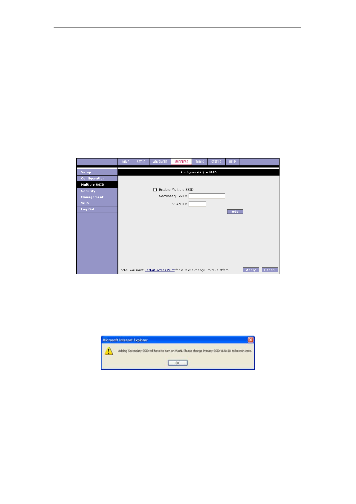
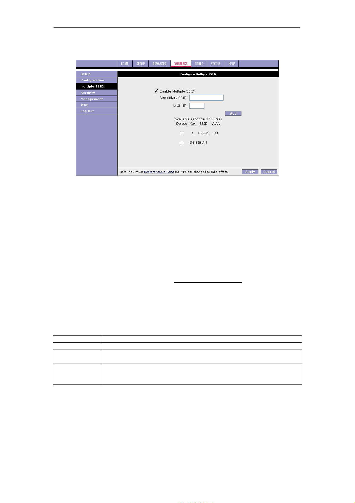
The Enable SSID field allows you to create multiple SSIDs for the AP. The Multiple SSID
feature supports up to two SSID (one primary and one secondary). You can see from Figure
4-6 that Multiple SSID feature is enabled by default and a secondary SSID has been created:
z Secondary SSID: TI-Voice_SSID
z VLAN ID: 2
You can disable multiple SSID or re-configure the secondary SSID; however, it is
recommended that you keep the default setting so that voice data over WLAN is given the
highest priority. To learn more about how WLAN QoS is handled, refer to ‘‘WLAN QoS
Support’.
You can create multiple SSIDs using the procedure describe below:
1. Check Enable Multiple SSID.
2. Enter the Secondary SSID and VLAN ID. Then click Add.
3. A pop-up message appears requesting you to change the Primary SSID’s VLAN ID to
be no-zero.
37
Page 39
SOHOSpeed ADSL2/2+ Ethernet/Wireless Gateway User’s Manual
4. Click OK. The SSID appears as shown in figure below.
Note: The SSID field takes up to 32 alpha-numeric characters.
5. Go to WLAN Configuration page, and change the VLAN ID to a number different from
zero (between 1 and 4095).
6. Repeat first part of step 2 to add more SSID.
Note: Up to 3 secondary SSIDs are supported (in addition to the primary SSID).
7. To delete an SSID, check the SSID, then click Delete in the pop-up window. To delete
all SSIDs, check Delete All.
Note: When the last secondary SSID is deleted, WLAN QoS is disabled and the VLAN
ID of the primary SSID is changed to the default 0.
8. Click Apply to complete the settings.
Note: The changes take effect when you click Apply; however, if the SOHOSpeed
configuration is not saved, these changes will be lost upon SOHOSpeed reboot.
9. After finish adding SSID, please refer to 3.5 Configuring the LAN to setup the LAN
configuration for each SSID.
10. To make the change permanent, click Tools at the top of the page and select System
Commands.
11. At the System Commands page, click Save All.
Field Description
Field
Enable Multiple
Secondary SSID
VLAN ID
Definition/Description
SSID Enables/disables multiple SSID.
The secondary SSID of the SOHOSpeed, is up to 32 characters and is
unique from the primary SSID.
The VLAN ID of the secondary SSID, which has a unique value between 1
- 4095. For more information on the VLAN ID of the primary SSID, refer to
‘‘Wireless Setup Page’’.
38
Page 40
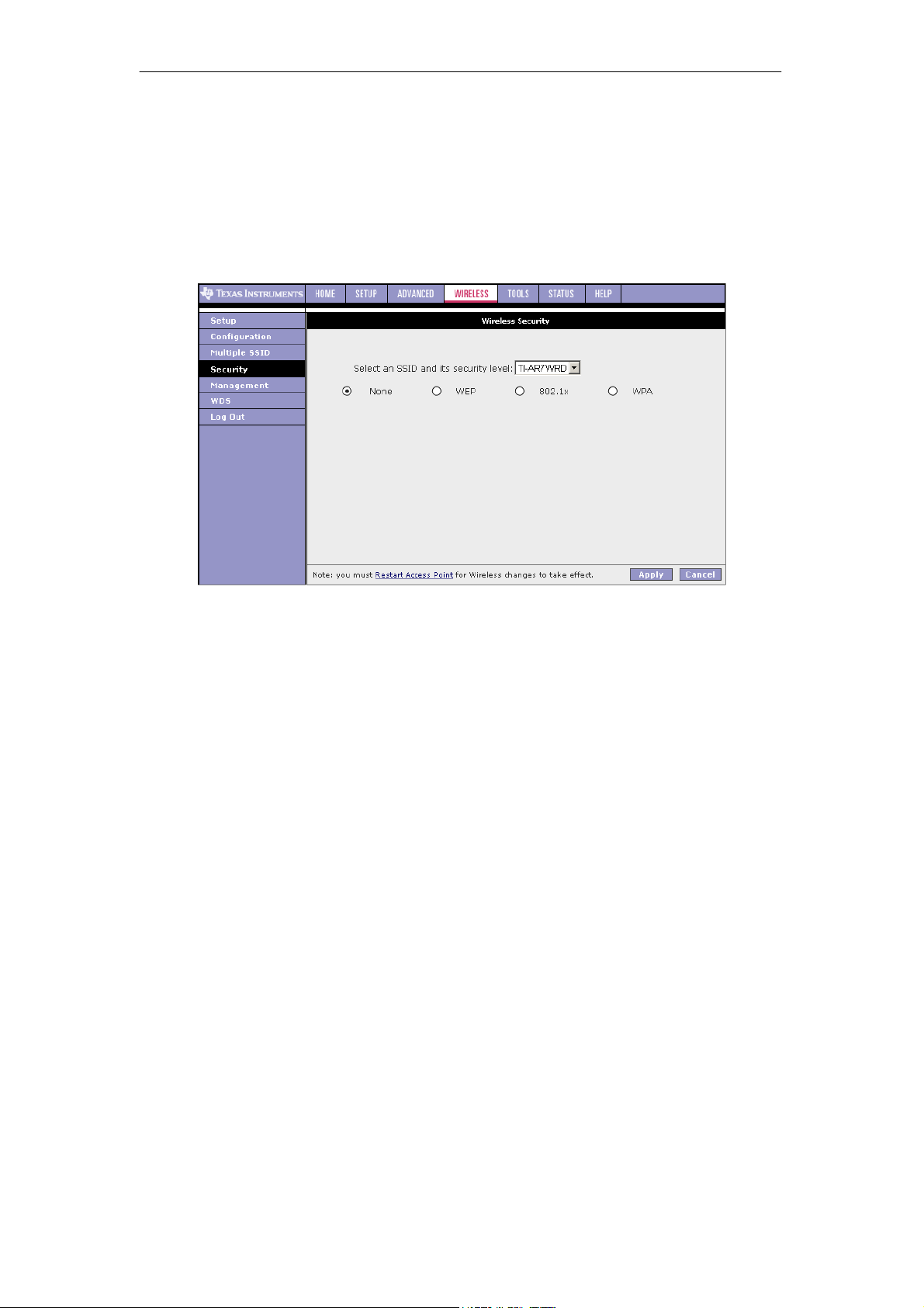
SOHOSpeed ADSL2/2+ Ethernet/Wireless Gateway User’s Manual
3.6.4 Wireless Security
The default Wireless Security page provides the following wireless network security options:
z None: No security used.
z Wired equivalent privacy (WEP): Enable legacy stations to connect the AP.
z 802.1x: Enable stations with 802.1x capability to connect the AP.
z Wi-Fi protected access (WPA): Enable stations with WPA capability to connect the AP.
z WPA2: Enable stations with WPA2 capability to connect the AP. This option is available
under the WPA option.
If you have multiple SSID enabled, you can assign security to each SSID. There are a few
rules/limitations that you should follow:
z WEP cannot be assigned to more than one SSID.
z 802.1x cannot be assigned to more than one SSID.
z WEP and 802.1x cannot both be assigned concurrently to different SSIDs.
z When more than one SSID exists with security enabled, the Authentication type for WEP
cannot be Shared.
WEP
WEP is a security protocol for WLAN. WEP provides security by encrypting the data that is
sent over the WLAN.
The SOHOSpeed supports three levels of WEP encryption:
z 64-bit encryption
z 128-bit encryption
z 256-bit encryption
With WEP, the receiving station must use the same key for decryption. Each radio network
interface card (NIC) and AP, therefore, must be manually configured with the same key.
39
Page 41
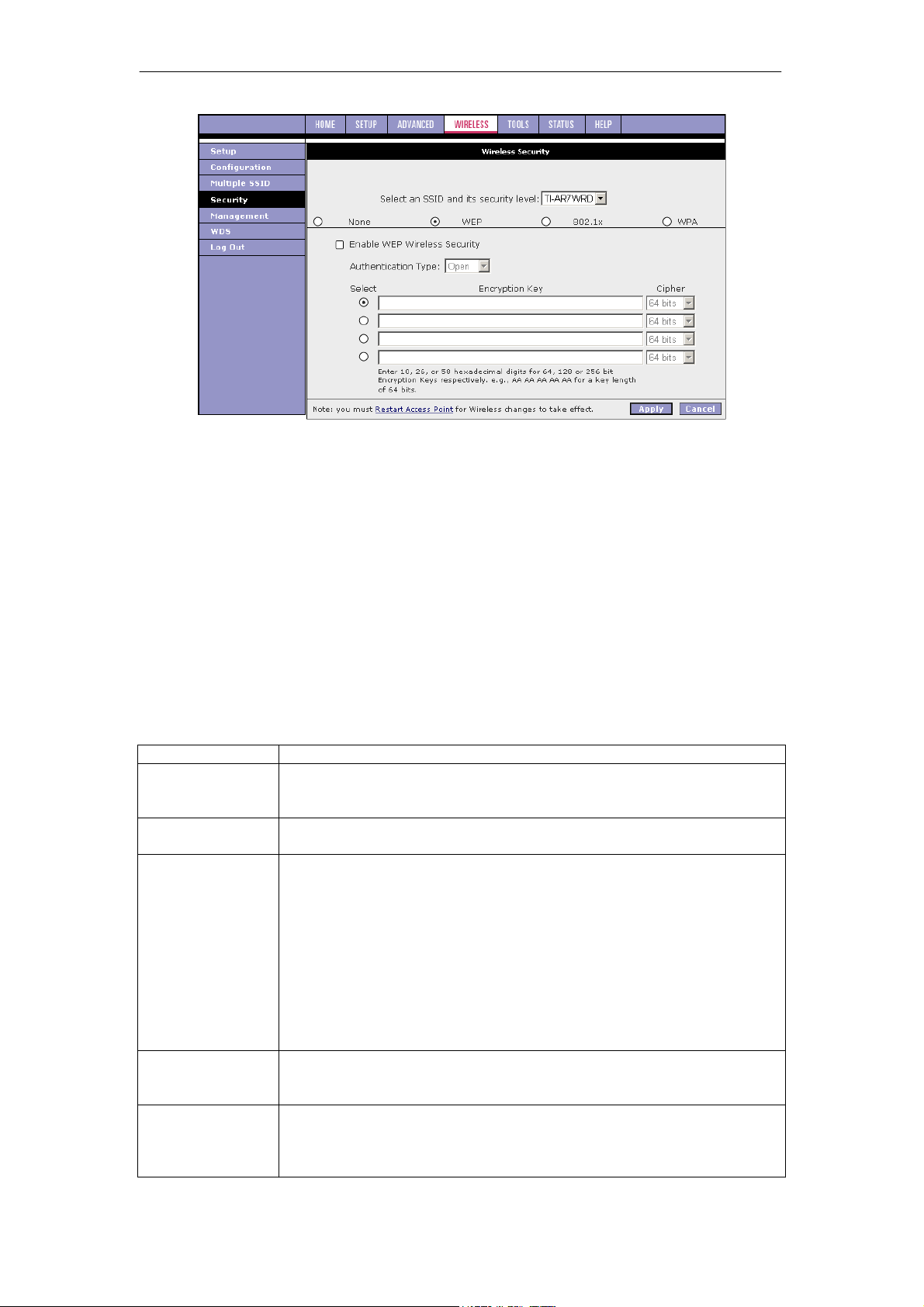
SOHOSpeed ADSL2/2+ Ethernet/Wireless Gateway User’s Manual
Follow the procedure below to enable WEP on yourSOHOSpeed.
1. Select the SSID that you want to apply security to.
2. Check Enable WEP Wireless Security.
3. Select Authentication Type.
4. Enter Encryption key and select Cipher following the instructions on the page.
You will need to enter the same key for the first time configuration of each station.
5. Click Apply to complete the settings.
Note: The changes take effect when you click Apply; however, if the SOHOSpeed
configuration is not saved, these changes will be lost upon SOHOSpeed reboot.
6. To make the change permanent, click Tools at the top of the page and select System
Commands.
7. At the System Commands page, click Save All.
Field Description
Field
Select an SSID
and its Security
Level
Enable WEP
Wireless Security
Authentication
Encryption Key
WEP Cipher
Definition/Description
If multiple SSID is enabled, use this drop-down menu to select the SSID
that you want to apply wireless security to.
Check this field to enable WEP wireless security on the selected SSID.
Type Authentication algorithm to use when the security configuration is
set to Legacy. When the security configuration is set to 802.1x or WPA,
the authentication algorithm is always open. This field is enabled when
the WEP security field is checked. There are three options:
z Open (default): In open-system authentication, the access point
accepts any station without verifying its identify.
z Shared: Shared-key authentication requires a shared key (WEP
encryption key) be distributed to the stations before attempting
authentication.
z Both: If both is selected, the access point will perform shared-key
authentication, then open-system authentication.
This field is enabled when the WEP security is checked to identify the
key value that is used when the security configuration is set to WEP. The
key length must match the WEP cipher.
This field is enabled when the WEP security field is checked. You can
select from 64 bits, 128 bits, and 256 bits. The WEP cipher that is used
when the security configuration is set to WEP. This field is not used when
the security configuration is set to 802.1x and WPA.
40
Page 42
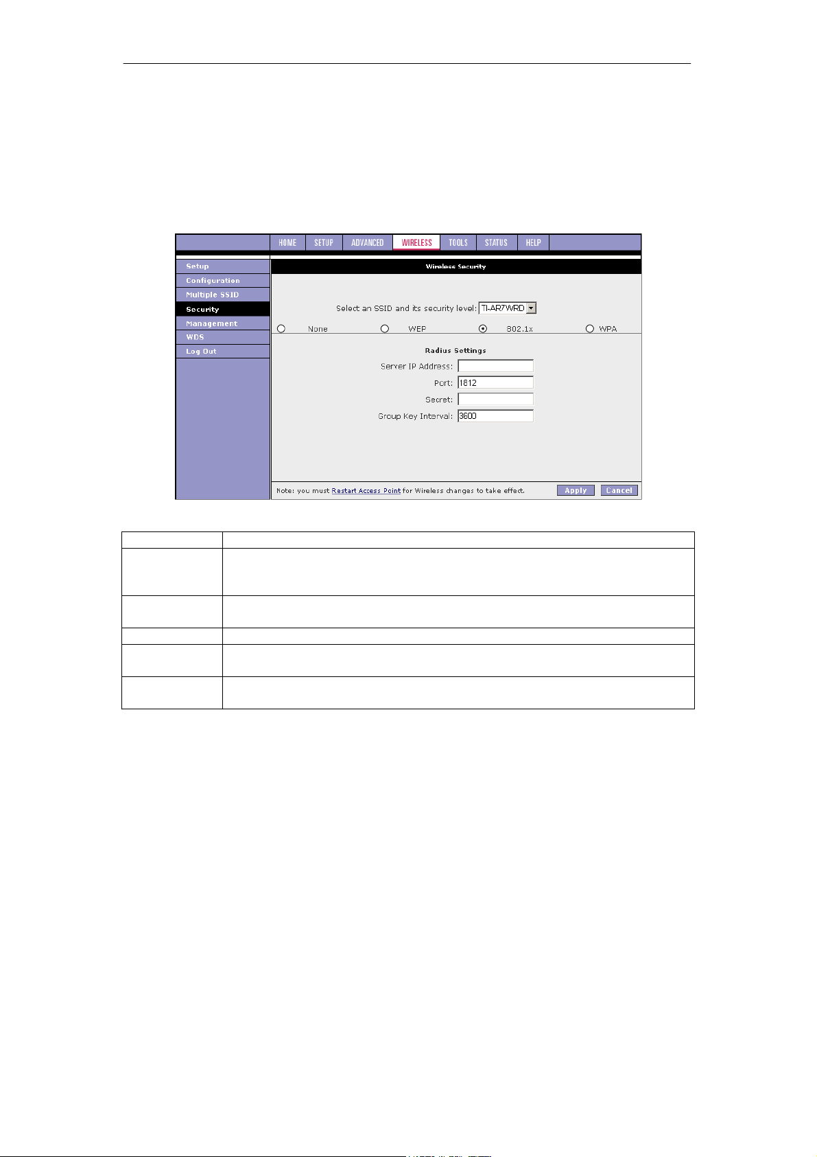
SOHOSpeed ADSL2/2+ Ethernet/Wireless Gateway User’s Manual
802.1x
802.1x is a security protocol for WLAN. It is a port-based network access control that keeps
the network port disconnected until authentication is completed. 802.1x is based on
extensible authentication protocol (EAP). EAP messages from the authenticator to the
authentication server typically use the remote authentication dial-in user service (RADIUS)
protocol. The figure below shows the default setting of the Wireless Security - 802.1x page.
Field Description
Field
Select an SSID
and its
Definition/Description
If multiple SSID is enabled, use this drop-down menu to select the SSID that
you want to apply wireless security to.
Security Level
Server IP
The IP address of the RADIUS server. Used for authentication.
Address
Port
Secret
The protocol port of the RADIUS server.
The secret that the AP shares with the RADIUS server. You can enter up to
63 alpha-numeric characters in this field.
Group Key
Interval
The group key interval that is used to distribute the group key to 802.1x and
WPA stations. The default value of this field is 3600 secs.
41
Page 43

SOHOSpeed ADSL2/2+ Ethernet/Wireless Gateway User’s Manual
WPA
WPA is a security protocol for WLAN. WPA uses a sophisticated key hierarchy that generates
new encryption keys each time a mobile device establishes itself with an AP. Protocols
including 802.1X, EAP, and RADIUS are used for strong authentication. Like WEP, keys can
still be entered manually (pre-shared keys); however, using a RADIUS authentication server
provides automatic key generation and enterprise-wide authentication. WPA uses temporal
key integrity protocol (TKIP) for data encryption. WPA2, also known as 802.11i, uses
advanced encryption standard counter mode CBC-MAC protocol (AES-CCMP) for data
encryption.
Field Description
Field Definition/Description
Select an SSID
and its
If multiple SSID is enabled, use this drop-down menu to select the SSID that
you want to apply wireless security to.
Security Level
WPA
WPA2
AnyWPA
Enable WPA2
Pre-
Enables stations that support WPA v.1 to connect to the AP.
Enables stations that support WPA v.2 to connect to the AP.
Enables stations that support WPA v.1 and WPA v.2 to connect to the AP.
Enables/disables WPA2 pre-authentication. This field is activated only when
WPA2 or AnyWPA is enabled.
authentication
Group Key
This value is measured in seconds.
Interval
Radius Server
When selected, the WPA stations authenticate with the RADIUS server using
extensible authentication protocol - transport layer security (EAP-TLS) over
802.1x.
IP Address
Port
Secret
IP address of the RADIUS server.
The protocol port of the RADIUS server.
The secret that the AP shares with the RADIUS server. You can enter up to
63 alpha-numeric characters in this field.
Pre-shared
Key
When selected, the WPA stations do not authenticate with the RADIUS
server using EAP-TLS. Instead they share a pre-shared secret with the AP
(ASCII format).
String
Pre-shared key string. The PSK string needs to be entered in the first-time
configuration of each station. You can enter 8 - 63 alpha-numeric characters
in this field.
42
Page 44
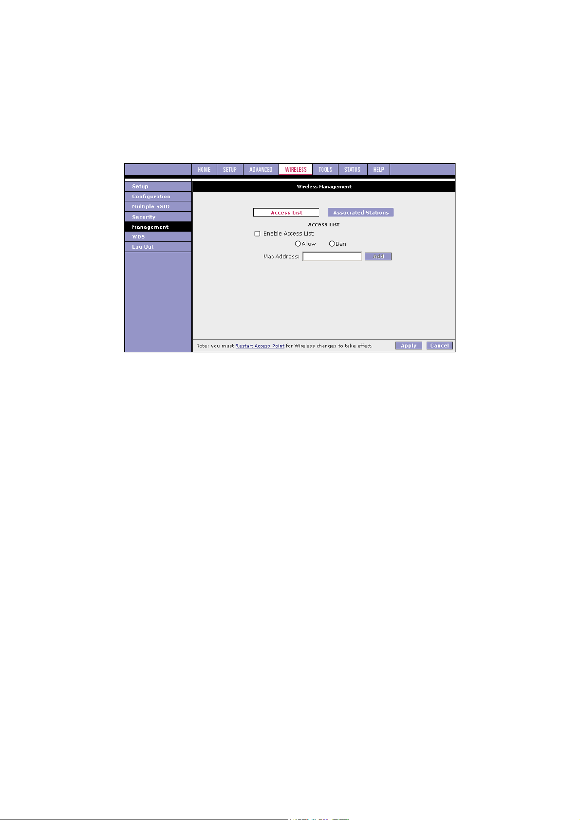
SOHOSpeed ADSL2/2+ Ethernet/Wireless Gateway User’s Manual
3.6.5 Wireless Management
The wireless management function gives another level of security to your AP. It allows you to
create an allowed access list or a banned access list (not both) and view a list of stations
associated with your access point.
Access List
By clicking Management from the left-hand navigation list, you are taken to the default Access
List page.
You can create an Allowed or Banned access list from the Access List page using Procedure
4-4.
1. Check Enable Access List.
2. Select Allow to create an allowed access list or Ban to create a banned list.
Note: You cannot create both.
3. Enter a MAC address of an allowed or banned station, then click Add.
This station appears in your allowed or banned access list.
4. Repeat this step for each station you want to add to your access list.
5. Click Apply to complete the settings.
Note: The changes take effect when you click Apply; however, if the SOHOSpeed
configuration is not saved, these changes will be lost upon SOHOSpeed reboot.
6. To make the change permanent, click Tools at the top of the page and select System
Commands.
7. At the System Commands page, click Save All.
43
Page 45
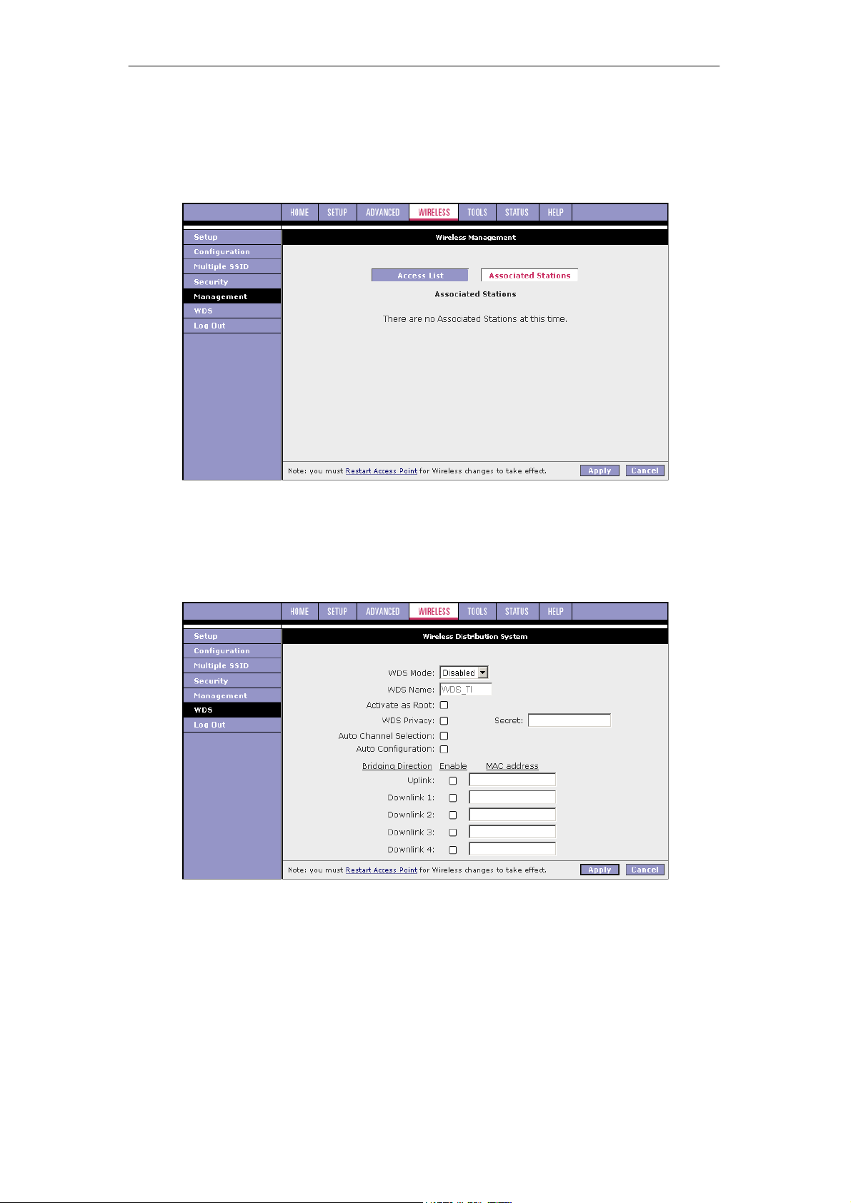
SOHOSpeed ADSL2/2+ Ethernet/Wireless Gateway User’s Manual
Associated Stations
This page allows you to see a list of all stations associated with the access point. You can
ban any stations on the list by clicking Ban Station next to the MAC Address. If the Allowed
Access list is enabled, this station will be deleted from the Allowed Access List. If the Banned
Access list is enabled, this station will be added to the Banned Access List.
3.6.6 WDS
Wireless distribution system (WDS) is a system that interconnects BSS to build a premise
wide network. WDS network allows users of mobile equipment to roam and stay connected to
the available network resources. You can configure your SOHOSpeed as WDS mode using
the WDS page.
44
Page 46

SOHOSpeed ADSL2/2+ Ethernet/Wireless Gateway User’s Manual
Field Description
Field Definition/Description
WDS Mode
The following WDS modes are available:
z Bridge: In Bridge mode, the AP basic service set (BSS) service is
enabled.
z Repeater: In Repeater mode, the AP BSS is disabled when connection to
the upper layer AP is established.
z Crude: In Crude mode, the AP BSS service is always enabled; however,
the links between APs are configured statically and are not maintained.
z Disabled (Default): WDS inactive.
z In Both Bridge and Repeater modes, WDS uses management protocol to
establish and maintain links between APs.
WDS Name
The WDS name is used to identify WDS network. The field takes up to eight
characters. Two or more WDS networks may exist in the same area.
Activate as
Root
This field must be checked for the root device in WDS hierarchy. Only one
WDS root device may exist in WDS network. This field is not applicable for
Crude mode.
WDS
Privacy
Checking this field commands WDS manager to use a secured connection
between APs in the WDS network. Security settings must be the same in all
APs in the WDS network.
Note: WDS privacy is not supported in Crude mode.
Secret
Auto
The 32-character alpha-numeric privacy key.
Auto channel selection is not supported in the current version.
Channel
Selection
Auto
Auto configuration is not supported in the current version.
Configuratio
n
Uplink
Connection
The BSS ID of the upper device in the WDS hierarchy. This uplink cannot be
configured if Root is enabled.
Check Box
Downlink
Connection
The BSS ID of the lower device in the WDS hierarchy connected to this AP. Up
to four downlinks can be configured.
Check
Boxes
45
Page 47
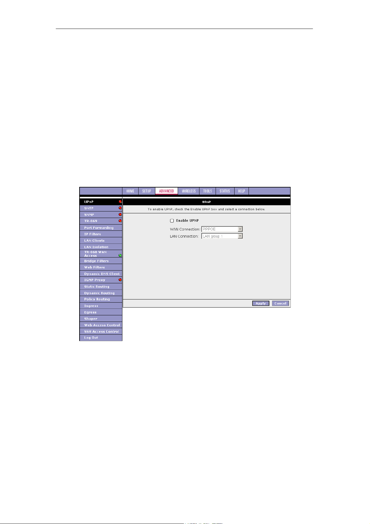
SOHOSpeed ADSL2/2+ Ethernet/Wireless Gateway User’s Manual
3.7 ADVANCED
The Advanced tab allows you to perform advanced configuration functions for existing
connections including:
z Enabling and disabling of key features including voice, voice provision, UPnP, SNTP,
SNMP, TR-069, IP QoS, RIP, access control, TR-068 WAN access, and multicasting
z QoS (ingress, egress, shaper) and policy routing
z Management of LAN port interfaces, packet flow, and filtering
At least one WAN connection must be configured before implementing advanced WAN
configuration features. At least one LAN group must be defined before implementing
advanced LAN configuration features.
3.7.1 UPnP
Universal plug and play (UPnP), NAT, and firewall traversal allow traffic to pass through the
SOHOSpeed for applications using the UPnP protocol. This feature requires one active WAN
connection. In addition, the PC should support this feature. In the presence of multiple WAN
connections, select a connection on which the incoming traffic is present, for example, the
default WAN connection.
1. Check Enable UPnP.
This enables the WAN Connection and LAN Connection fields.
2. Select the WAN Connection and LAN Connection that will use UPnP from the drop-
down lists.
3. Click Apply to temporarily activate the settings.
Note: The changes take effect when you click Apply; however, if the SOHOSpeed
configuration is not saved, these changes will be lost upon SOHOSpeed reboot.
4. To make the change permanent, click Tools at the top of the page and select System
Commands.
5. At the System Commands page, click Save All.
46
Page 48
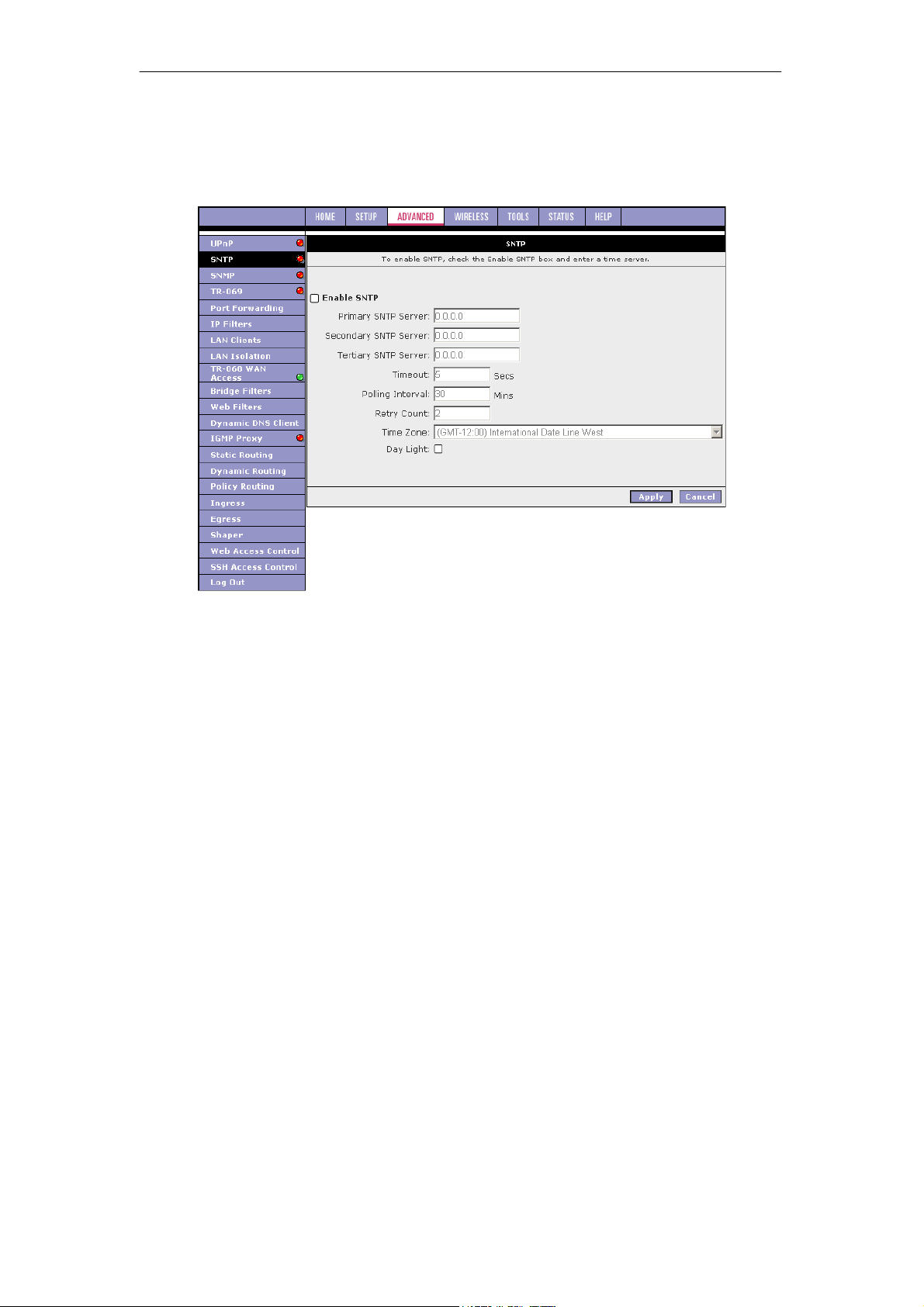
SOHOSpeed ADSL2/2+ Ethernet/Wireless Gateway User’s Manual
3.7.2 SNTP
Simple network timing protocol (SNTP) is a protocol used to synchronize the system time to
the public SNTP servers. It uses the UDP protocol on port 123 to communicate between
clients and servers. The figure below shows the default SNTP page.
When the SNTP feature is enabled, your SOHOSpeed starts querying for the time clock
information from the primary SNTP server. If it fails to get a valid response within the Timeout
period, it makes additional attempts based on the number specified in the Retry Count field
before moving to the Secondary SNTP server.
If it fails to get a valid response from Secondary STNP server within the specified retry count,
it starts querying the Tertiary SNTP server. If it fails to get a valid response from all the
servers, then the program stops. Once a valid response is received from one of the servers,
the program goes to sleep for number of minutes specified in the Polling Interval field before
starting the whole process again.
1. Check Enable SNTP.
2. Use the table below as a reference and configure the following fields:
z Primary SNTP Server
z Secondary SNTP Server
z Tertiary SNTP Server
z Timeout
z Polling Interval
z Retry Count
z Time Zone
z Day Light
3. Click Apply to temporarily activate the settings.
Note: The changes take effect when you click Apply; however, if the SOHOSpeed
configuration is not saved, these changes will be lost upon SOHOSpeed reboot.
4. To make the change permanent, click Tools at the top of the page and select System
Commands.
5. At the System Commands page, click Save All.
47
Page 49
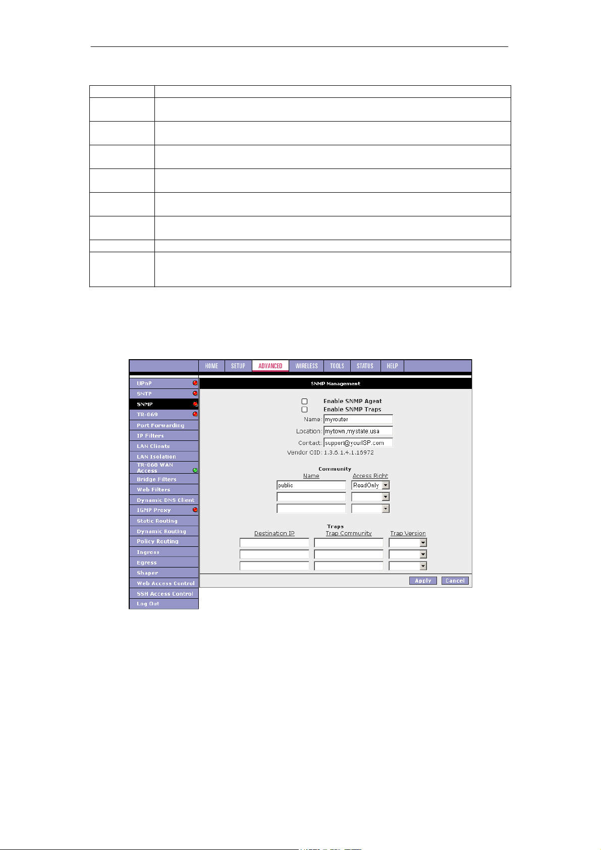
SOHOSpeed ADSL2/2+ Ethernet/Wireless Gateway User’s Manual
Field Description
Field Definition/Description
Primary
SNTP Server
Secondary
SNTP Server
Tertiary
SNTP Server
Timeout
Polling
Interval
Retry Count
Time Zone
Day Light
The IP address or the host name of the primary SNTP server. This can be
provided by ISP or user-defined.
The IP address or the host name of the secondary SNTP server. This can be
provided by ISP or user-defined.
The IP address or the host name of the tertiary SNTP server. This can be
provided by ISP or user-defined.
If the SOHOSpeed failed to connect to a SNTP server within the Timeout
period, it retries the connection.
The amount of time between a successful connection with a SNTP server and
a new attempt to connect to an SNTP server.
The number of times the SOHOSpeed tries to connect to an SNTP server
before it tries to connect to the next server in line.
The time zone in which the SOHOSpeed resides.
Check/uncheck this option to enable/disable daylight saving time (DST).
Note: DST is not automatically enabled or disabled. You need to manually
enable and disable it.
3.7.3 SNMP
Simple network management protocol (SNMP) is a troubleshooting and management protocol
that uses the UDP protocol on port 161 to communicate between clients and servers. The
figure below shows the default SNMP page.
SNMP uses a Manager- Management information base (MIB)-Agent solution to fulfill network
management needs. The manager is a separate station that can request data from an SNMP
agent, which resides in each modem on the network. The agent uses the MIBs as dictionaries
of manageable objects. The SNMP agent supports GET, SET, GETNEXT, and TRAP for four
groups with MIB-II: System, Interface, IP, and ICMP.
48
Page 50

SOHOSpeed ADSL2/2+ Ethernet/Wireless Gateway User’s Manual
Field Description
Field Definition/Description
Enable SNMP
The SNMP agent is enabled by default.
Agent
Enable SNMP
SNMP traps are enabled to send by default.
Traps
Name
Location
Contact
Vendor OID
An administratively-assigned name for the SOHOSpeed.
The physical location of the SOHOSpeed.
Contact person and/or contact information for the SOHOSpeed.
Vendor object identifier. The vendor's authoritative identification of the
network management subsystem contained in the entity. This value is
allocated within the SMI enterprises subtree (1.3.6.1.4.1). For example,
Texas Instruments was assigned the subtree 1.3.6.1.4.1.294.
Community
SNMP defines a community to be a relationship between an SNMP agent
and one or more SNMP managers. Once the clear-text community name
corresponds to a community known to the receiving SNMP entity, the
sending SNMP entity is considered to be authenticated as a member of
that community and is granted different levels of access: read-only or readwrite. The combination of community access mode and a MIB-managed
project defines the community profile for each object.
The community profile defines the operations that can be applied to the
object. In the SOHOSpeed, a default community name of public with
access mode of read-only is created in the configuration file. It allows a
GET or a GETNEXT operation to all objects with access rights of READONLY and READ-WRITE in the MIB.
In the SOHOSpeed, up to three community names can be configured
through the web page. The view_subtrees of SNMPv2c and user-based
security model and view-based access control model of SNMPv3 will be
supported in future SNMP agent development.
Community
Name
Community
Access Right
Name of community. SNMP supports up to 3 communities including the
default community name of public.
Two options are offered:
z ReadOnly: Allows a GET or a GETNEXT operation to all objects in
the MIB.
z ReadWrite: Allows ReadOnly access right to all objects and SET
operation to objects defined as read-writable in the MIB.
Trap
Trap is an event notification. There are four standard traps supported in the
SOHOSpeed:
z WarmStartTrap
z LinkUpTrap
z LinkDownTrap
z AuthenticationFailureTrap
Trap Destination
IP
Trap Community
Trap Version
Destination IP address of the trap. Traps can be sent to three different
destinations.
Community name of the trap.
Two trap versions/formats are supported:
z SNMP v1
z SNMP v2c
49
Page 51
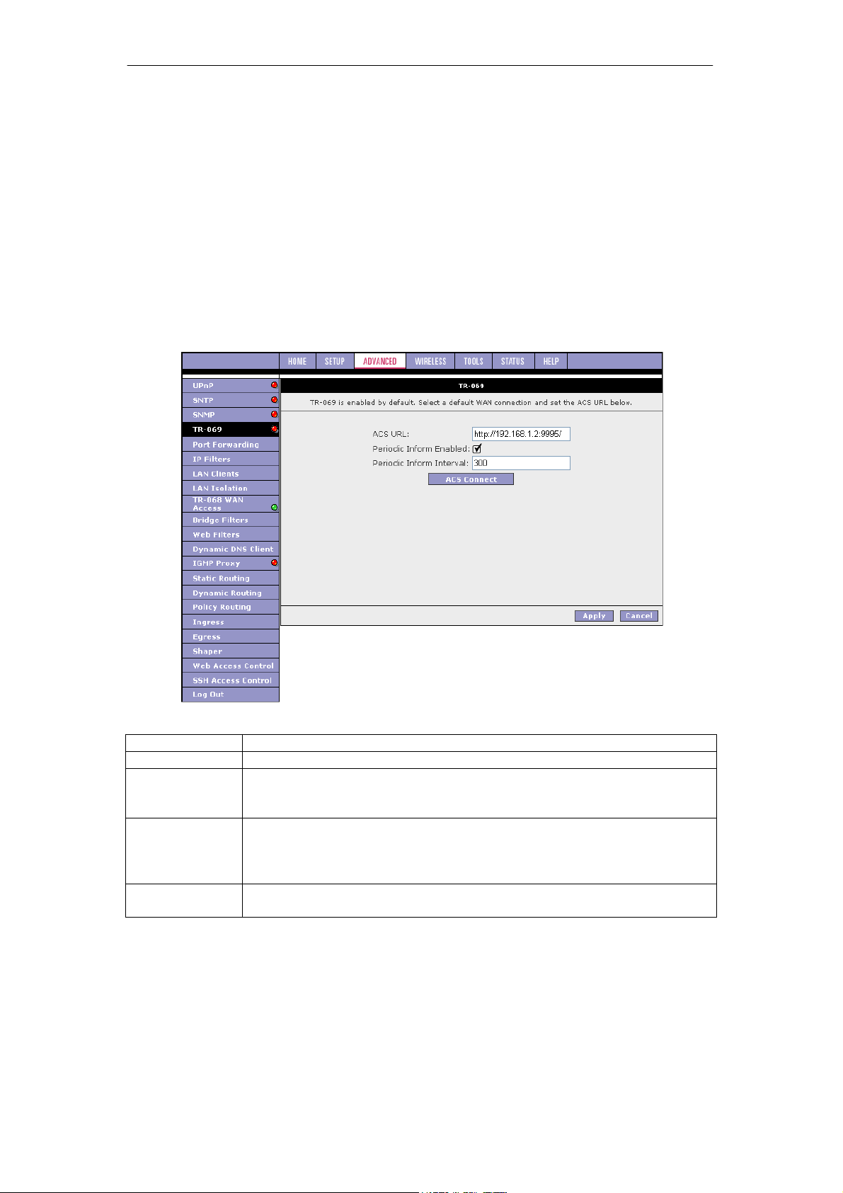
SOHOSpeed ADSL2/2+ Ethernet/Wireless Gateway User’s Manual
3.7.4 TR-069
TR-069 is CPE Management Protocol from WAN side, intended for communication between a
CPE and Auto-Configuration Server (ACS). The CPE WAN Management Protocol defines a
mechanism that encompasses secure auto-configuration of a CPE, and also incorporates
other CPE management functions into a common framework.
The CPE WAN Management Protocol is intended to support a variety of functionalities to
manage a collection of CPE, including the following primary capabilities:
z Auto-configuration and dynamic service provisioning
z Software/firmware image management
z Status and performance monitoring
z Diagnostics
The TR-069 page allows you to set up connection parameters and may not be seen by the
end user. The figure below shows the default TR-069 page.
Field Description
Field Definition/Description
ACS URL
Periodic Inform
Enabled
Periodic Inform
Interval
ACS Connect
URL of the auto configuration server (ACS) provided by the ISP.
Enable/disables the SOHOSpeed to connect to the ACS periodically. If you
enable this feature, you should enter a value in the Periodic Inform Interval
field.
This field is enabled only when the Periodic Inform Enabled field is
checked. It defines the amount of time (in seconds) between a successful
connection with an ACS server and a new attempt to connect to an ACS
server. A recommended value is 86400 seconds (1 day).
By clicking the ACS Connect button, you manually connect the
SOHOSpeed to the ACS.
50
Page 52

SOHOSpeed ADSL2/2+ Ethernet/Wireless Gateway User’s Manual
Please refer to TR-69 “Field Description” and follow procedure below to configure parameters
related to TR-69.
1. Leave the default URL in the ACS URL field .
2. Check Periodic Inform Enabled and enter a value in the Periodic Inform Interval field.
or
Click ACS Connect to manually connect to the ACS. Once a connection is established,
the ACS can update all three fields: ACS URL, Periodic Inform Enabled, and Periodic
Inform Interval.
3. Click Apply when you finish to temporarily activate the settings.
Note: The changes take effect when you click Apply; however, if the SOHOSpeed
configuration is not saved, these changes will be lost upon SOHOSpeed reboot.
4. To make the change permanent, click Tools at the top of the page and select System
Commands.
5. At the System Commands page, click Save All.
3.7.5 Port Forwarding
The port forwarding (or virtual server) feature allows you to direct incoming traffic to specific
LAN hosts based on a protocol port number and protocol.
Using the Port Forwarding page, you can provide local services (for example, web hosting) for
people on the Internet or play Internet games. Port forwarding is configurable per LAN group.
A database of predefined port forwarding rules allows you to apply one or more rules to one
or more members of a defined LAN group. You can view the rules associated with a
predefined category and add the available rules for a given category. You can also create,
edit, or delete your own port forwarding rules.
51
Page 53
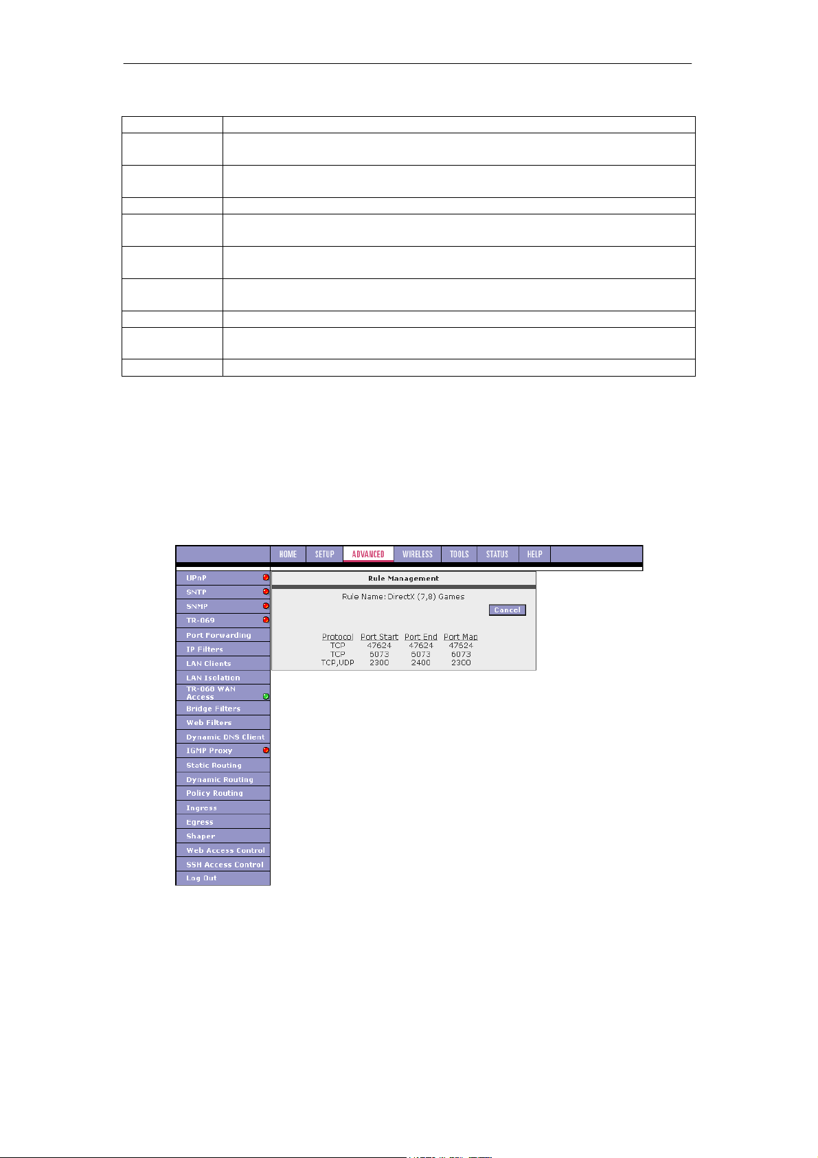
SOHOSpeed ADSL2/2+ Ethernet/Wireless Gateway User’s Manual
Field Description
Field
WAN
Connection
Select LAN
Group
LAN IP
Allow
Incoming Ping
DMZ
Custom Port
Forwarding
Category
Available
Rules
Applied Rules
Definition/Description
Select the WAN connection to which port forwarding is applied.
Select the LAN Group to which port forwarding is applied.
Select the IP address to host the service.
Enabling incoming ping (ICMP) requests on the Port Forwarding page allows
the SOHOSpeed to respond to a ping from the Internet.
Demilitarized zone. More information on DMZ is available in "DMZ Settings
Page".
This link takes you to the Custom Port Forwarding page. More information is
available in "Custom Port Forwarding Page".
Custom and user-defined categories.
Predefined and user-defined IP filtering rules for each category.
Lists the IP filtering rules you elect to apply for each given category.
6. On the Port Forwarding Configuration page, select WAN Connection, LAN Group,
and LAN IP.
If the desired LAN IP is not available in the LAN IP drop-down menu, you can add it
using the LAN Client page, which is accessed by clicking New IP.
7. Select the available rules for a given category and click Add to apply the rule for this
category.
Note: You can click View to view the rule associated with a predefined filter on the Rule
Management page.
52
Page 54
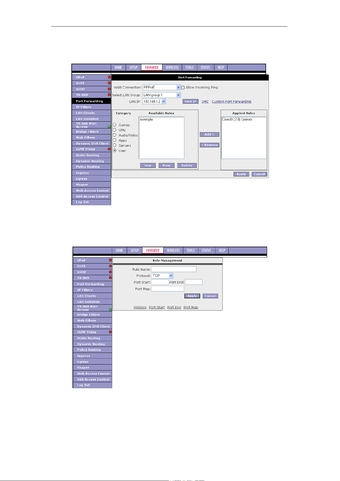
SOHOSpeed ADSL2/2+ Ethernet/Wireless Gateway User’s Manual
8. If a rule is not in the list, you can create your own rule in the User category.
Select User, then click New
Note: The New, View, and Delete buttons become available only when the User category is
selected. All the custom rules you create fall under the User Category.
9. The Rule Management page populates for you to create new rules. Enter Rule Name,
Protocol, Port Start, Port End, and Port Map fields, then click Apply.
The rules you create become available in the User category. You are able to view or
delete the rules you create.
10. Continue to add rules as they apply from each category.
11. Click Apply when you finish to temporarily activate the settings.
Note: The changes take effect when you click Apply; however, if the SOHOSpeed
configuration is not saved, these changes will be lost upon SOHOSpeed reboot.
53
Page 55
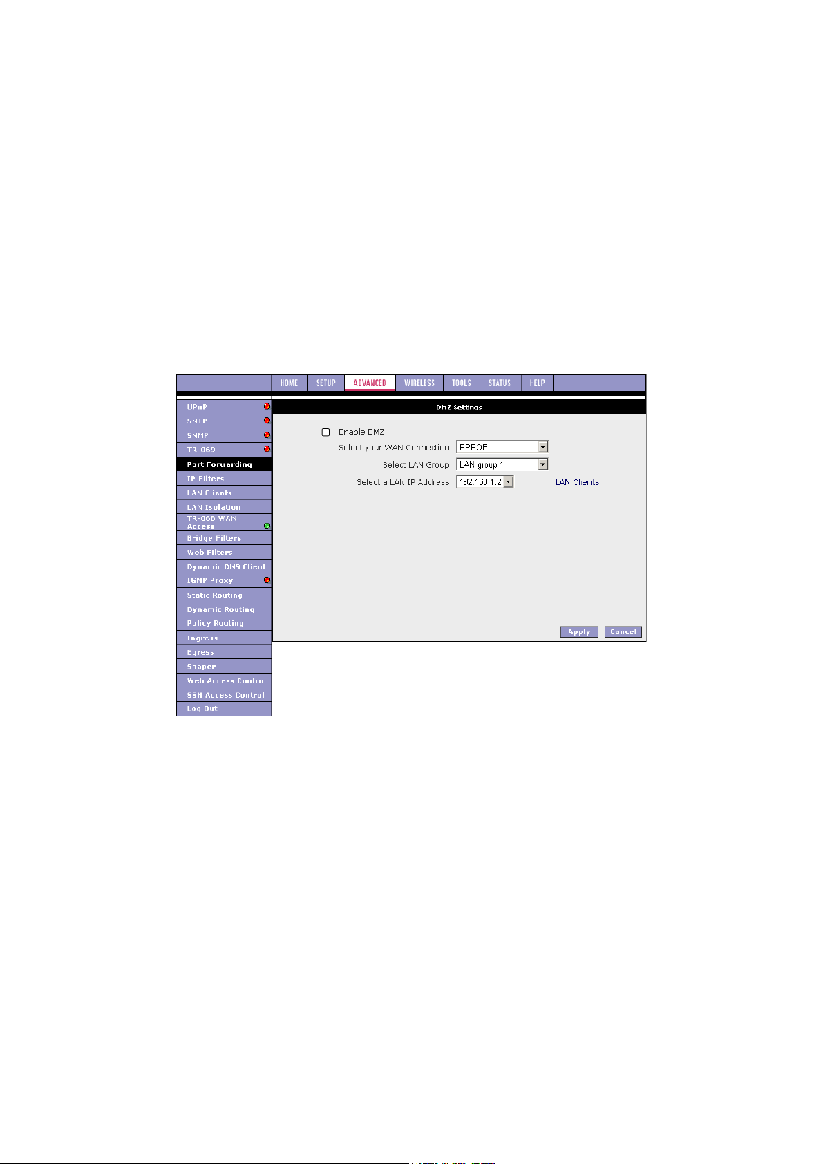
SOHOSpeed ADSL2/2+ Ethernet/Wireless Gateway User’s Manual
12. To make the change permanent, click Tools at the top of the page and select System
Commands.
13. At the System Commands page, click Save All.
Note: You can also use the Custom Port Forwarding link to add programs to the existing list.
DMZ Settings Page
Setting a host on your local network as demilitarized zone (DMZ) forwards any network traffic
that is not redirected to another host via the port forwarding feature to the IP address of the
host. This opens the access to the DMZ host from the Internet. This function is disabled by
default. By enabling DMZ, you add an extra layer of security protection for hosts behind the
firewall.
1. On the Port Forwarding page, click the DMZ link.
You are taken to the DMZ Settings page.
2. Check the Enable DMZ box.
3. Select the WAN Connection, LAN Group, and LAN IP Address.
DMZ is configurable per LAN segment.
4. Click Apply when you finish to temporarily activate the settings.
Note: You can access the LAN Clients page by clicking the LAN Clients link.
Note: The changes take effect when you click Apply; however, if the SOHOSpeed
configuration is not saved, these changes will be lost upon SOHOSpeed reboot.
5. To make the change permanent, click Tools at the top of the page and select System
Commands.
6. At the System Commands page, click Save All.
54
Page 56

Field Description
Field
Enable DMZ
Select your
WAN
Connection
Select LAN
Group
Select a LAN IP
Address
LAN Clients
SOHOSpeed ADSL2/2+ Ethernet/Wireless Gateway User’s Manual
Definition/Description
Enables/disables the Demilitarized Zone feature. This field is unchecked
(disabled) by default.
Select the WAN connection on which the DMZ feature is applied.
Select the LAN Group on which the DMZ feature is applied.
Select the LAN IP address you are going to use as the DMZ host. This host
is exposed to the Internet. Be aware that this feature may expose your
local network to security risks.
This link takes you to the LAN Clients page. More information on LAN
Clients can be found in "LAN Clients Page".
55
Page 57

SOHOSpeed ADSL2/2+ Ethernet/Wireless Gateway User’s Manual
Custom Port Forwarding Page
The Custom Port Forwarding page allows you to create up to 15 custom port forwarding
entries to support specific services or applications, such as concurrent NAT/NAPT operation.
Field Description
Field
Connection
Enable
Application
Protocol
Source IP
Address
Source Netmask
Destination IP
Address
Destination
Netmask
Destination Port
Start
Destination Port
End
Destination Port
Map
Definition/Description
Select the WAN connection on which the Custom Port Forwarding rule is to
be applied.
The Enable button is checked by default, meaning this rule is automatically
applied when you click the Apply button.
Name of the application for which your ports will be opened.
There are three options available: TCP, UDP, and TCP and UDP.
You can define the source IP address from which the incoming traffic is
allowed. Enter 0.0.0.0 for all.
Netmask of the source IP address. Enter 255.255.255.255 for all.
The LAN-side destination IP address for incoming traffic.
The LAN-side destination netmask for incoming traffic. The default value of
this field is 255.255.255.255.
The starting port number that is made open for this application.
The ending port number that is made open for this application.
Destination port mapped on the LAN (destination) side to which packets
are forwarded. There are two types of port mapping:
z One-to-one (one port mapped to one)
z Multiple-to-one (multiple ports mapped to one port)
Note: Wildcard (*) entries are allowed for IP Address/Netmask and Port range fields.
56
Page 58
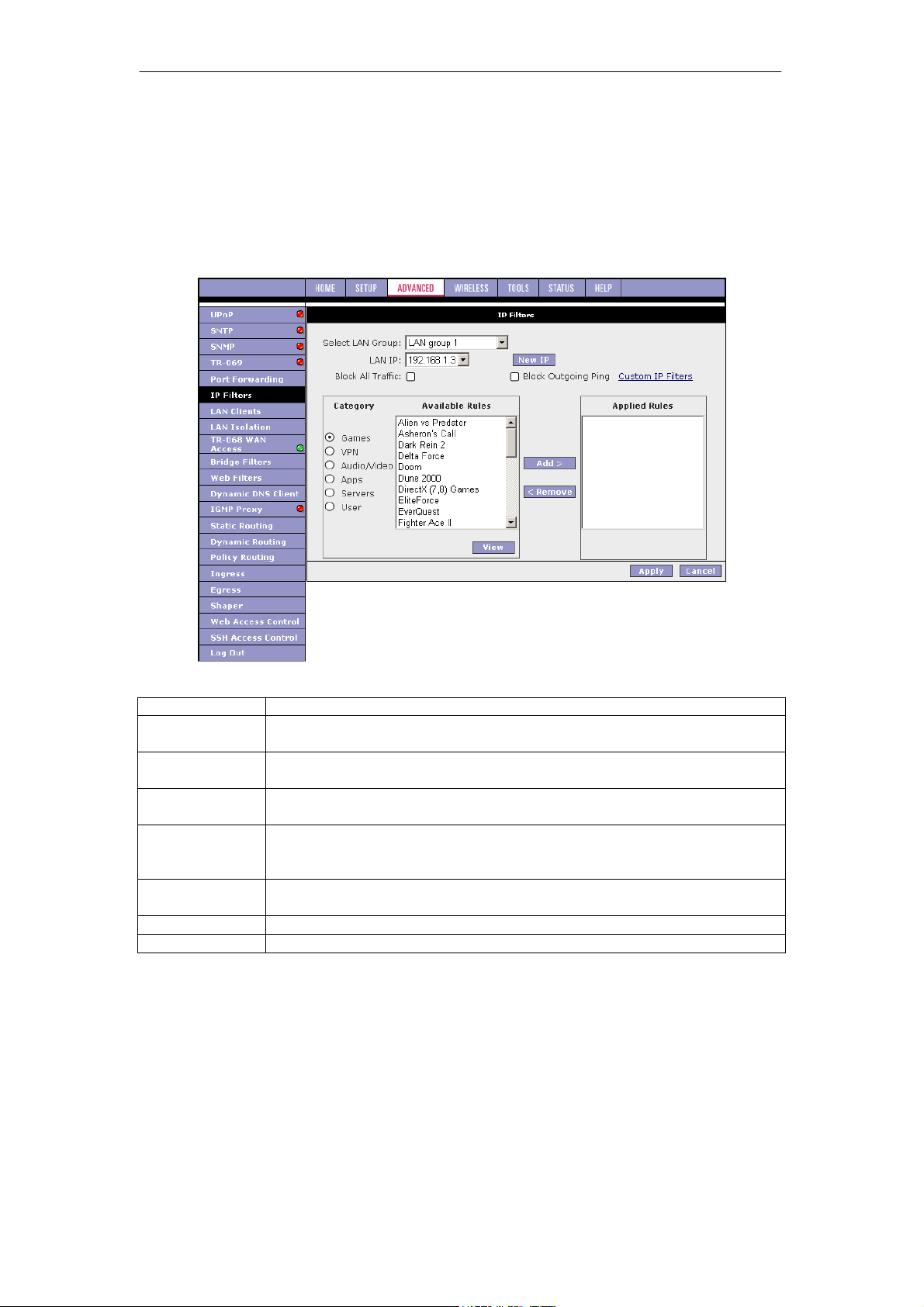
SOHOSpeed ADSL2/2+ Ethernet/Wireless Gateway User’s Manual
3.7.6 IP Filters
The IP filtering feature allows you to block specific applications/services based on the IP
address of a LAN device. You can use the IP Filters page to block specific traffic (for example,
block web access) or any traffic from a host on your local network.
A database of predefined IP filters allows you to apply one or more filtering rules to one or
more members of a defined LAN group. You can view the rules associated with a predefined
filter and add the available rules for a given category. You can also create, edit, or delete your
own IP filter rules.
Field Description
Field
Select LAN
Group
LAN IP
Block All Traffic
Block Outgoing
Ping
Custom IP
Filters
Available Rules
Applied Rules
Definition/Description
Select the LAN group to which the IP fIlters feature will be applied.
Select the IP address in the given LAN group to which the IP Filters feature
will be applied.
When checked, complete network access is blocked for the specific IP
address.
Blocking outgoing ping (ICMP) generated from a particular LAN IP can be
used if your host has a virus that attempts a Ping-of-Death Denial of
Service attack.
This link takes you to the Custom IP Filters page. More information is
available in "Custom IP Filters Page".
Predefined and user-defined IP filtering rules for each category.
Lists the IP filtering rules you elect to apply for each given category.
1. On the IP Filters page, select LAN Group and LAN IP.
If the desired LAN IP is not available in the LAN IP drop-down menu, you can add it
using the LAN Client page, which is accessed by clicking New IP.
2. Select the available rules for a given category. Click View to view the rule associated
with a predefined filter. Click Add to apply the rule for this category.
57
Page 59
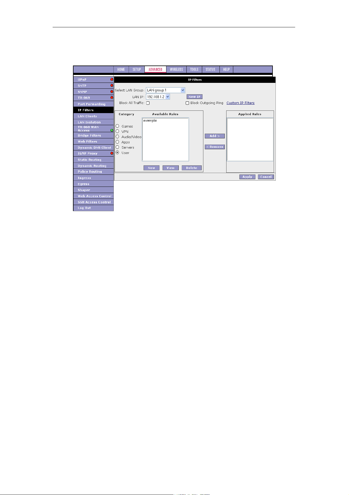
SOHOSpeed ADSL2/2+ Ethernet/Wireless Gateway User’s Manual
3. If a rule is not in the list, you can create your own rule in the User category.
Select User, then click New.
Note: The New, View, and Delete buttons become available only when the User
category is selected. All the custom rules you create fall under the User Category.
4. The Rule Management page populates for you to create new rules. Enter Rule Name,
Protocol, Port Start, Port End, and Port Map fields, then click Apply.
The rules you create appear in the Available Rules box in the User category.
You can view or delete the rules you create.
5. Continue to add rules as they apply from each category using the Add button.
6. Click Apply when you finish to temporarily activate the settings.
Note: The changes take effect when you click Apply; however, if the SOHOSpeed
configuration is not saved, these changes will be lost upon SOHOSpeed reboot.
7. To make the change permanent, click Tools at the top of the page and select System
Commands.
8. At the System Commands page, click Save All.
58
Page 60
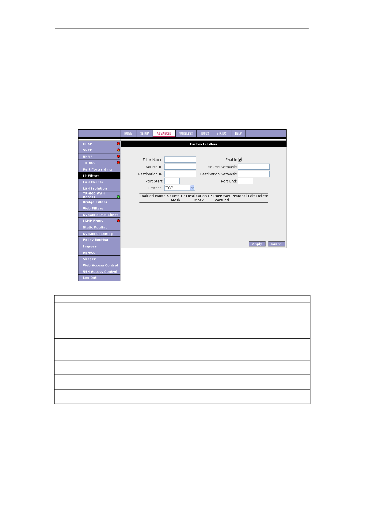
SOHOSpeed ADSL2/2+ Ethernet/Wireless Gateway User’s Manual
Custom IP Filters Page
The Custom IP Filters page allows you to define up to 20 custom IP filtering entries to block
specific services or applications based on:
z Source/destination IP address and netmask
z TCP port (ranges supported)
z Protocol
z TCP
z UDP
z TCP and UDP
z ICMP
z Any
Field Description
Field Definition/Description
Filter Name
Enable
Name of the IP filter rule you are creating.
The Enable button is checked by default, meaning this rule is automatically
applied when you click Apply.
Source IP
The LAN-side source IP address assigned to outgoing traffic on which
filtering is applied.
Source Netmask
Destination IP
Netmask of the source IP on your LAN side.
You can define the destination IP address to which your source IP will be
banned access. Enter 0.0.0.0 for all.
Destination
Netmask of the destination IP. Enter 255.255.255.255 for all.
Netmask
Port Stat
Port End
Protocol
The starting port number that will be blocked for this application.
The ending port number that will be blocked for this application.
There are five options available: TCP, UDP, TCP and UDP, ICMP, and
Any.
59
Page 61

SOHOSpeed ADSL2/2+ Ethernet/Wireless Gateway User’s Manual
3.7.7 LAN Clients
The LAN clients feature allows you to see all the hosts on the LAN segment.
Each host is qualified to be either dynamic (host obtained a lease from this SOHOSpeed) or
static (host has a manually-configured IP address).
You can add a static IP address (belonging to the SOHOSpeed’s LAN subnet) using the LAN
Clients page. Any existing static entry falling within the DHCP server's range can be deleted
and the IP address is made available for future allocation.
Note: Dynamic clients show up in the list only when the DHCP server is running.
1. On the LAN Clients page, select LAN Connection, and enter IP Address, Hostname,
and MAC Address.
2. Click Apply.
The IP address is allocated and it shows up in the list of LAN clients as a Dynamic entry.
60
Page 62
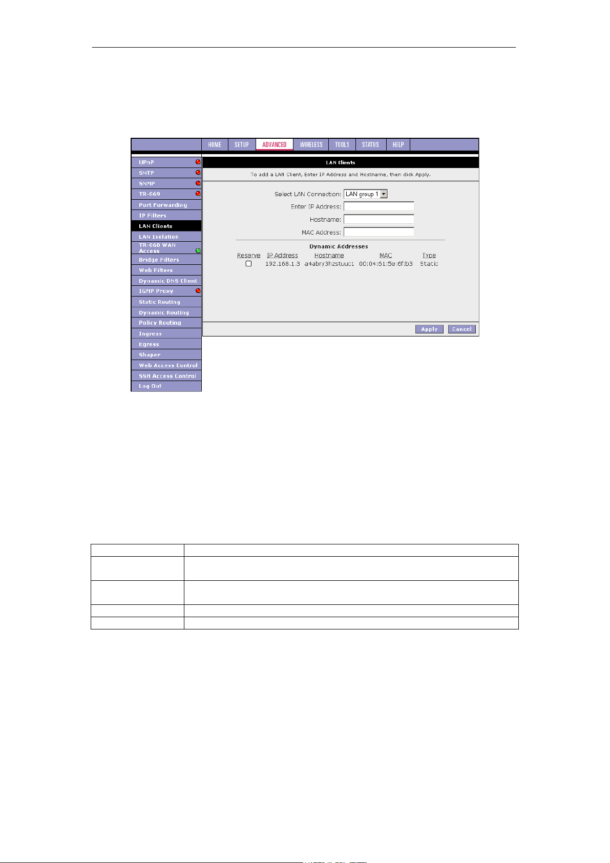
SOHOSpeed ADSL2/2+ Ethernet/Wireless Gateway User’s Manual
3. You can convert the dynamic entry into a static entry by clicking Reserve, then Apply.
As shown in figure below, the IP is now changed to a Static address. You can delete this
entry by selecting Delete.
4. When you finish, click Apply to temporarily activate the settings.
Note: The changes take effect when you click Apply; however, if the SOHOSpeed
configuration is not saved, these changes will be lost upon SOHOSpeed reboot.
5. To make the change permanent, click Tools at the top of the page and select System
Commands.
6. At the System Commands page, click Save All.
Note: The firewall rules that are applied to a Dynamic IP address will be removed after the
release time expires.
Field Description
Field Definition/Description
Select LAN
Connection
Enter IP Address
Hostname
MAC Address
Select the LAN connection to which the client is to be added.
Assign the dynamic IP address to the host here. This is a mandatory
field.
Hostname of the client. This is an optional field.
MAC address of the host. This is an optional field.
61
Page 63
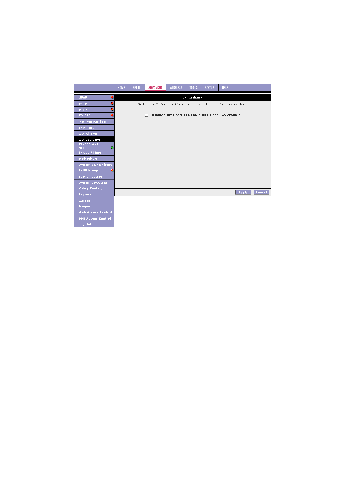
SOHOSpeed ADSL2/2+ Ethernet/Wireless Gateway User’s Manual
3.7.8 LAN Isolation
The LAN Isolation page allows you to disable the flow of packets between up to five userdefined LAN groups (interfaces include WLAN, USB, Ethernet, SSID1, SID2, and SSID3).
This allows you to secure information in private portions of the LAN (such as a hot spot
deployment) from other publicly accessible LAN segments.
1. Check the LAN group combinations that define which traffic will be blocked.
2. Click Apply to temporarily activate the settings.
Note: The changes take effect when you click Apply; however, if the SOHOSpeed
configuration is not saved, these changes will be lost upon SOHOSpeed reboot.
3. To make the change permanent, click Tools at the top of the page and select System
Commands.
4. At the System Commands page, click Save All.
62
Page 64
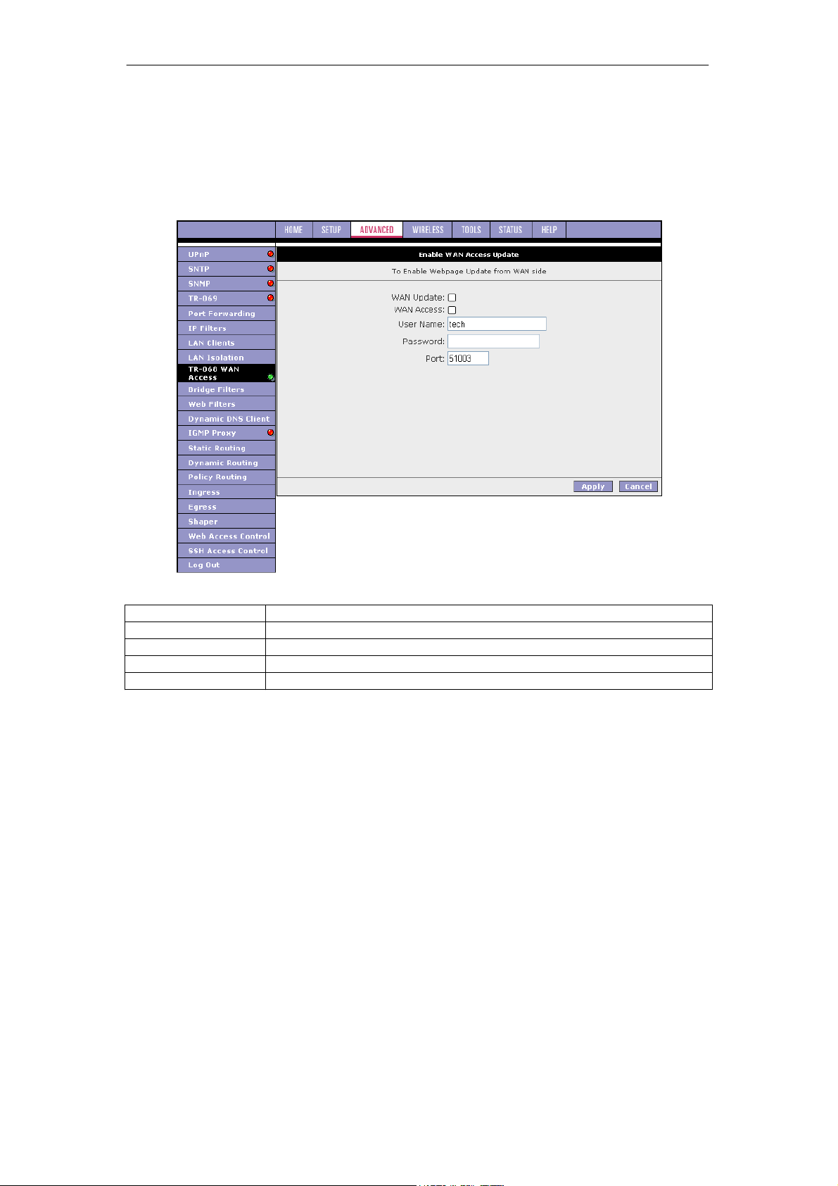
SOHOSpeed ADSL2/2+ Ethernet/Wireless Gateway User’s Manual
3.7.9 TR-068 WAN Access
The TR-068 WAN Access page enables you to give temporary permission to someone (such
as technical support staff) to be able to access your SOHOSpeed from the WAN side. From
the moment the account is enabled, the user is expected to log in within 20 active minutes,
otherwise the account expires. Once the user has logged in, if the session remains inactive
for more than 20 minutes, the user will be logged out and the account expires.
Field Description
Field Definition/Description
WAN Update
WAN Access
User Name
Password
To create a temporary user account for a remote access to your RG, use TR-68 “Field
Description” as a reference and follow procedure below.
Check this field to give the account read and write access.
Check this field to give the account read-only access.
User name of the WAN access account.
Password of the WAN access account.
1. Check WAN Update to enable write privilege of the SOHOSpeed.
2. Check WAN Access to enable read privilege of the SOHOSpeed.
3. Enter a user name and password in the User Name and Password fields.
4. Enter a port number In the Port field (for example, 51003).
5. Click Apply to temporarily activate the settings.
Note: The changes take effect when you click Apply; however, if the SOHOSpeed
configuration is not saved, these changes will be lost upon SOHOSpeed reboot.
6. To make the change permanent, click Tools at the top of the page and select System
Commands.
7. At the System Commands page, click Save All.
8. To access your SOHOSpeed remotely, enter the following in the URL:
http(s)://10.10.10.5:51003
Syntax: http(s)://WAN IP of SOHOSpeed:Port Number
63
Page 65
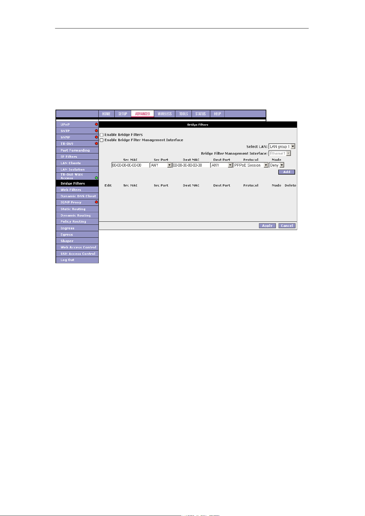
SOHOSpeed ADSL2/2+ Ethernet/Wireless Gateway User’s Manual
3.7.10 Bridge Filters
The bridge filtering mechanism provides a way for you to define rules to allow or deny frames
through the bridge based on source MAC address, destination MAC address, frame type, and
physical ports. When bridge filtering is enabled, each frame is examined against every
defined filter rule in sequence. When a match is found, the appropriate filtering action (allow
or deny) is performed.
Note that the bridge filter only examines frames from interfaces that are part of the bridge
itself. Up to 20 filter rules are supported with bridge filtering.
1. Check Enable Bridge Filters.
2. To add a rule, enter the source MAC address, destination MAC address, and frame type
with desired filtering type, then click Add.
Note: You can also edit a rule that you created using the Edit checkbox. You can delete
a rule using Delete.
3. Click Apply to temporarily activate the settings.
Note: The changes take effect when you click Apply; however, if the SOHOSpeed
configuration is not saved, these changes will be lost upon SOHOSpeed reboot.
4. To make the change permanent, click Tools at the top of the page and select System
Commands.
5. At the System Commands page, click Save All.
Note: There are four hidden filter rules within the bridge filter table. These rules are entered to
ensure you do not "lock" yourself out of the SOHOSpeed on a particular port. The rules
pertain to the combination of source/destination MAC addresses, source/destination ports,
and protocols.
64
Page 66

SOHOSpeed ADSL2/2+ Ethernet/Wireless Gateway User’s Manual
Field Description
Field Definition/Description
Enable Bridge
Filters
Enables/disables bridge filtering. It can be set/unset during any add,
edit, or delete operation. It can also be set/unset independently by
clicking Apply.
Enable Bridge Filter
Management
Interface
Select LAN
When checked, it enables the Bridge Filter Management Interface field.
This ensures that you do not get locked out of the SOHOSpeed on the
interface of the LAN group specified in the next two fields.
Select your LAN group to enable the Bridge Filter Management
Interface feature.
Bridge Filter
Management
Interface
Select the interface of the LAN group to have the Bridge Filter
Management Interface feature enabled. Depending on the LAN group
that is selected, the interface selections are Ethernet, USB, and/or
WLAN.
SRC MAC
The source MAC address. It must be in a xx-xx-xx-xx-xx-xx format,
with 00-00-00-00-00-00 as don't care. Blanks can be used in the MAC
address space and are also considered as don't care.
SRC Port
Source port. You can choose from Any, Ethernet, USB, WLAN, or
WAN Bridge Connection Port for the particular bridge. If any of the
selections are not available, please check your DSL connection.
Dest MAC
Dest Port
The destination MAC address.
Destination port. You can choose from Any, Ethernet, USB, and
WLAN.
Protocol You can choose from the following options: PPPoE Session,
PPPoE Discovery, IPX - Ethernet II, RARP, IPv6, IPv4, and Any.
Mode
There are two filtering modes: Deny and Allow.
65
Page 67
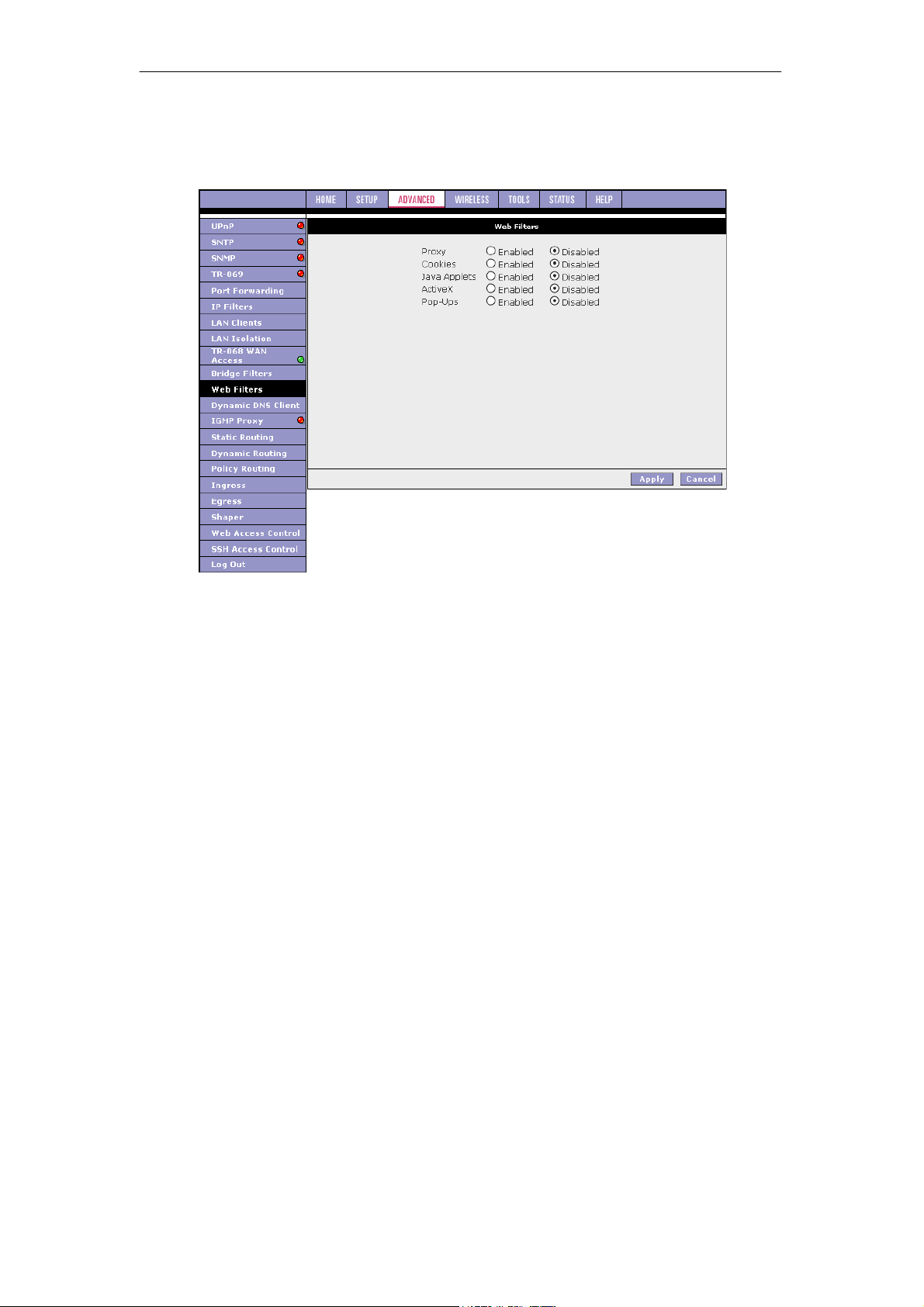
SOHOSpeed ADSL2/2+ Ethernet/Wireless Gateway User’s Manual
3.7.11 Web Filters
The Web Filters page allows you to manage the type of web content that passes through your
SOHOSpeed.
The following web filters are disabled by default:
z Proxy server
z Cookies
z Java applets
z ActiveX controls
z Pop-ups
To enable a web filter, check Enabled next to the filter name, then click Apply.
66
Page 68
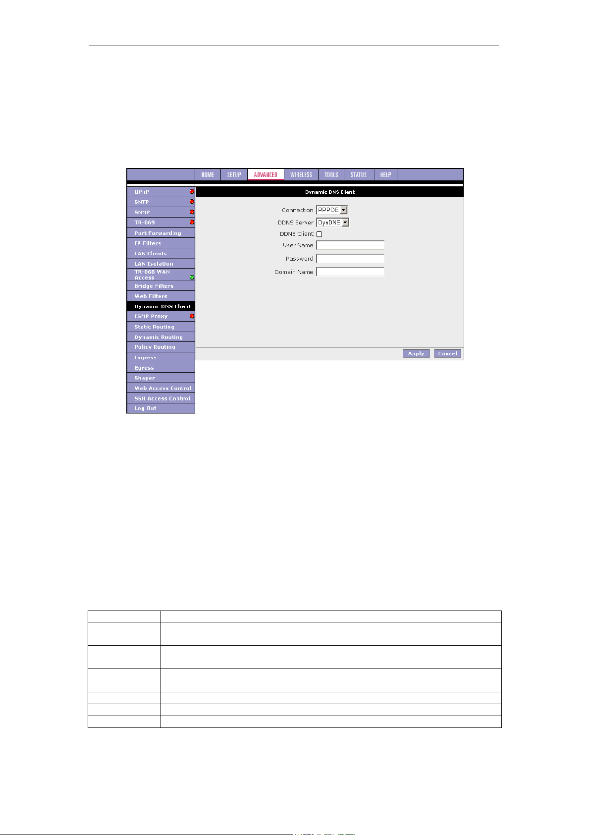
SOHOSpeed ADSL2/2+ Ethernet/Wireless Gateway User’s Manual
3.7.12 Dynamic DNS Client
Each time your SOHOSpeed connects to the Internet, your ISP assigns a different IP address
to your SOHOSpeed. In order for you or other users to access your SOHOSpeed from the
WAN-side, you need to manually track the IP that is currently used. The Dynamic DNS
feature allows you to register your SOHOSpeed with a DNS server and access your
SOHOSpeed each time using the same host name. The Dynamic DNS Client page allows
you to enable/disable the Dynamic DNS feature.
1. On the Dynamic DNS Client page, configure the following fields:
z Connection
z DDNS Server
z DDNS Client
z User Name
z Password
z Domain Name
2. Click Apply to temporarily activate the settings.
Note: The changes take effect when you click Apply; however, if the SOHOSpeed
configuration is not saved, these changes will be lost upon SOHOSpeed reboot.
3. To make the change permanent, click Tools at the top of the page and select System
Commands.
4. At the System Commands page, click Save All.
Field Description
Field Definition/Description
Connection
DDNS Server
DDNS Client
User Name
Password
Domain Name
This field defaults to your SOHOSpeed’s WAN connection over which your
SOHOSpeed will be accessed.
This is where you select the server from different DDNS service providers.
A charge may occur depends on the service you select.
Enables/disables the DDNS client feature for the WAN connection. This field
is disabled by default.
User name assigned by the DDNS service provider.
Password assigned by the DDNS service provider.
Domain name to be registered with the DDNS server.
67
Page 69
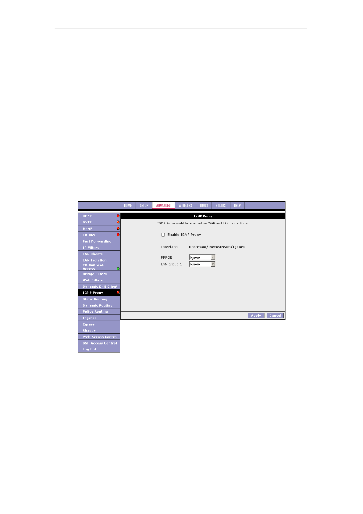
SOHOSpeed ADSL2/2+ Ethernet/Wireless Gateway User’s Manual
3.7.13 IGMP Proxy
Multicasting is a form of limited broadcast. UDP is used to send datagrams to all hosts that
belong to what is called a Host Group. A host group is a set of one or more hosts identified by
a single IP destination address. The following statements apply to host groups:
z Anyone can join or leave a host group at will.
z There are no restrictions on a host’s location.
z There are no restrictions on the number of members that may belong to a host group.
z A host may belong to multiple host groups.
z Non-group members may send UDP datagrams to the host group.
Multicasting is useful when the same data needs to be sent to more than one device. For
instance, if one device is responsible for acquiring data that many other devices need, then
multicasting is a natural fit. Note that using multicasting as opposed to sending the same data
to individual devices uses less network bandwidth. The multicast feature also enables you to
receive multicast video streams from multicast servers.
IP hosts use Internet group management protocol (IGMP) to report their multicast group
memberships to neighboring routers. Similarly, multicast routers use IGMP to discover which
of their hosts belong to multicast groups.
Your SOHOSpeed supports IGMP proxy that handles IGMP messages. When enabled, your
SOHOSpeed acts as a proxy for a LAN host making requests to join and leave multicast
groups, or a multicast router sending multicast packets to multicast groups on the WAN side.
The IGMP Proxy page allows you to enable multicast on available WAN and LAN connections.
You can configure the WAN or LAN interface as one of the following:
1. Upstream: The interface that IGMP requests from hosts are sent to the multicast router.
2. Downstream: The interface data from the multicast router are sent to hosts in the
multicast group database.
3. Ignore: No IGMP request nor data multicast are forwarded.
You can perform one of the two options:
1. Configure one or more WAN interface as the upstream interface.
2. Configure one or more LAN interface as the upstream interface.
Each option is discussed in more details as follows.
68
Page 70
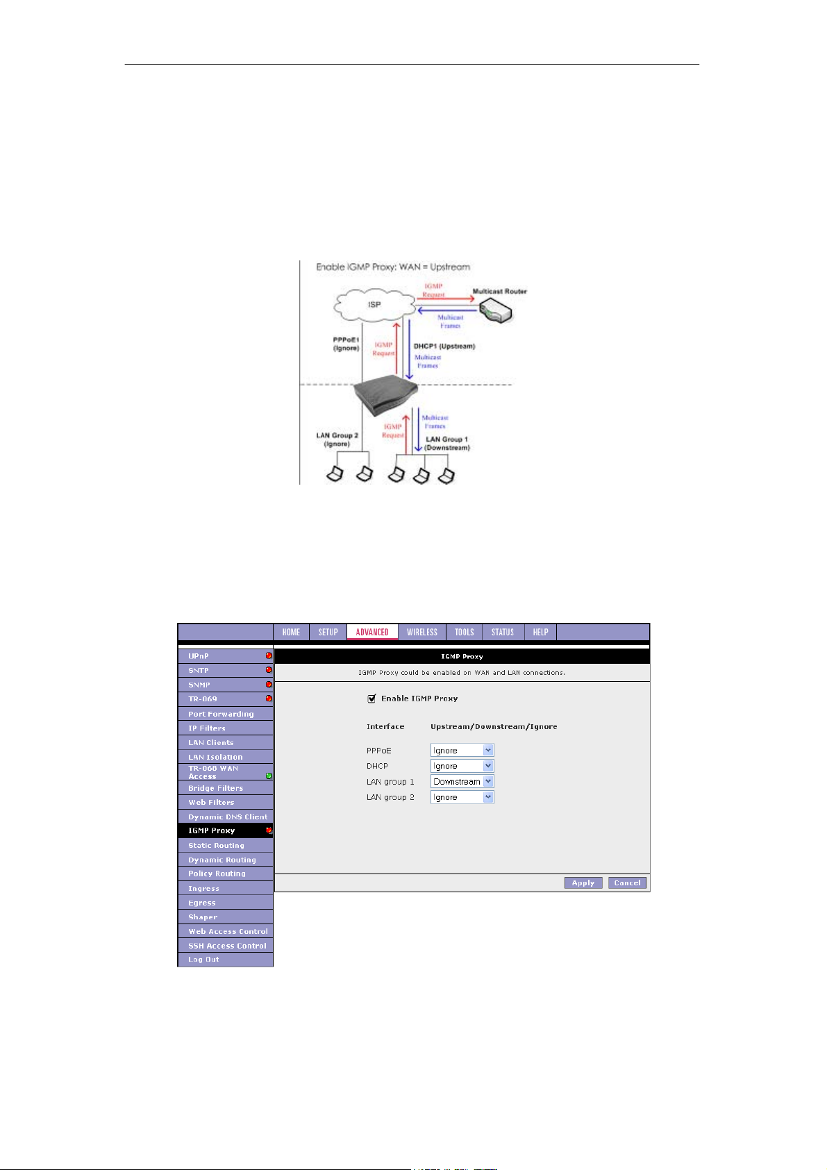
SOHOSpeed ADSL2/2+ Ethernet/Wireless Gateway User’s Manual
Configure a WAN Interface as the Upstream IGMP Proxy
This applies when the multicast server in on the network. Hosts on your LAN side can send
IGMP requests through the WAN interface. And the WAN will pass multicast packets from the
multicast server to the hosts on the LAN side.
In figure as shown below, the WAN interface DHCP1 is enabled as the upstream IGMP
interface, which forwards IGMP requests from LAN group 1 to the multicast router on the
network and forwards multicast frames from the multicast router to hosts on the downstream
interface (LAN group 1). No IGMP request nor data multicast are forwarded to PPPoE1 or
LAN Group 2.
1. Check Enable IGMP Proxy.
2. Configure the following WAN/LAN interfaces:
z PPPoE: Ignore
z DHCP: Upstream
z LAN group 1: Downstream
z LAN group 2: Ignore
69
Page 71
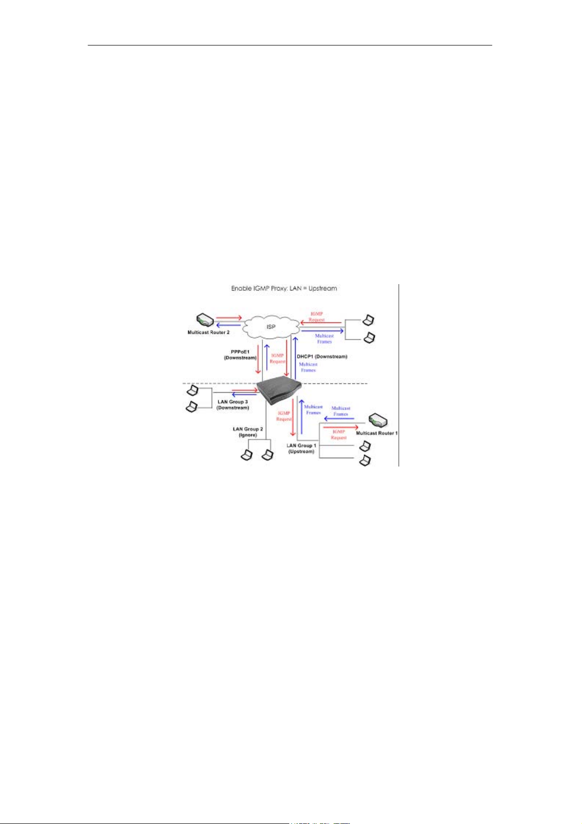
SOHOSpeed ADSL2/2+ Ethernet/Wireless Gateway User’s Manual
3. Click Apply to temporarily activate the settings.
Note: The changes take effect when you click Apply; however, if the SOHOSpeed
configuration is not saved, these changes will be lost upon SOHOSpeed reboot.
4. To make the change permanent, click Tools at the top of the page and select System
Commands.
5. At the System Commands page, click Save All.
Configure a LAN interface as the Upstream Interface
This applies when the multicast server in on the LAN side. Hosts on the network can sent
IGMP request from the WAN side through the LAN interface. And the LAN interface, acting as
the upstream interface, forwards data multicast from the LAN-side multicast server to hosts
on the network.
In figure as shown below, there is a multicast router on the LAN side and LAN Group 1
interface is enabled as the upstream IGMP proxy. IGMP requests from the network are
forwarded to LAN group 1 and multicast frames from multicast router 1 are forwarded to hosts
on the LAN side (LAN group 3) and on the WAN side (DHCP1 and PPPoE1). Neither IGMP
request nor data multicast are forwarded to LAN Group 2.
1. Check Enable IGMP Multicast.
70
Page 72
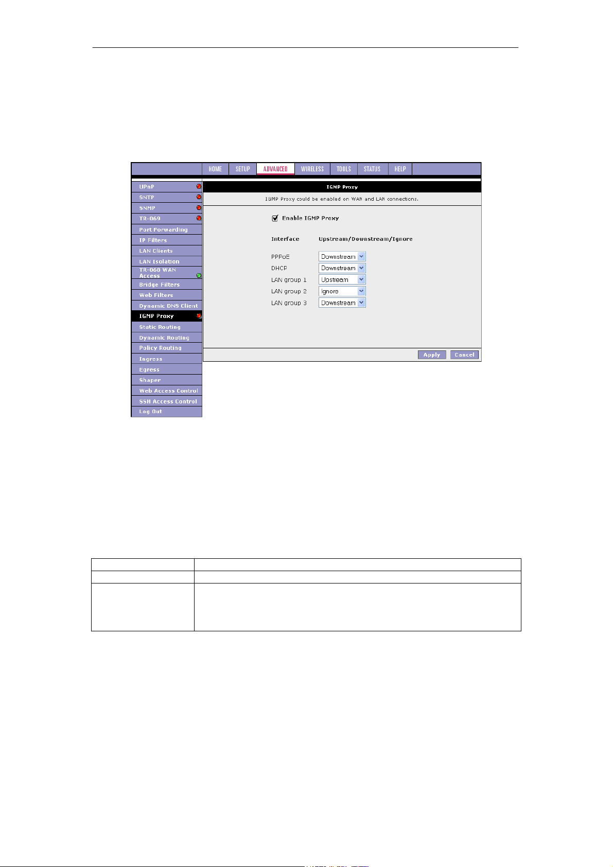
SOHOSpeed ADSL2/2+ Ethernet/Wireless Gateway User’s Manual
2. Configure the following WAN/LAN interfaces:
z PPPoE: Downstream
z DHCP: Downstream
z LAN group 1: Upstream
z LAN group 2: Ignore
z LAN group 3: Downstream
3. Click Apply to temporarily activate the settings.
Note: The changes take effect when you click Apply; however, if the SOHOSpeed
configuration is not saved, these changes will be lost upon SOHOSpeed reboot.
4. To make the change permanent, click Tools at the top of the page and select System
Commands.
5. At the System Commands page, click Save All.
Note: At least one WAN interface should be configured in order to enable the IGMP proxy.
Field Description
Field Definition/Description
Enable IGMP Proxy
Connections
Enables/disables IGMP multicast feature of the SOHOSpeed.
There are three types of configuration for each WAN /LAN connection:
z Upstream
z Downstream
z Ignore
71
Page 73
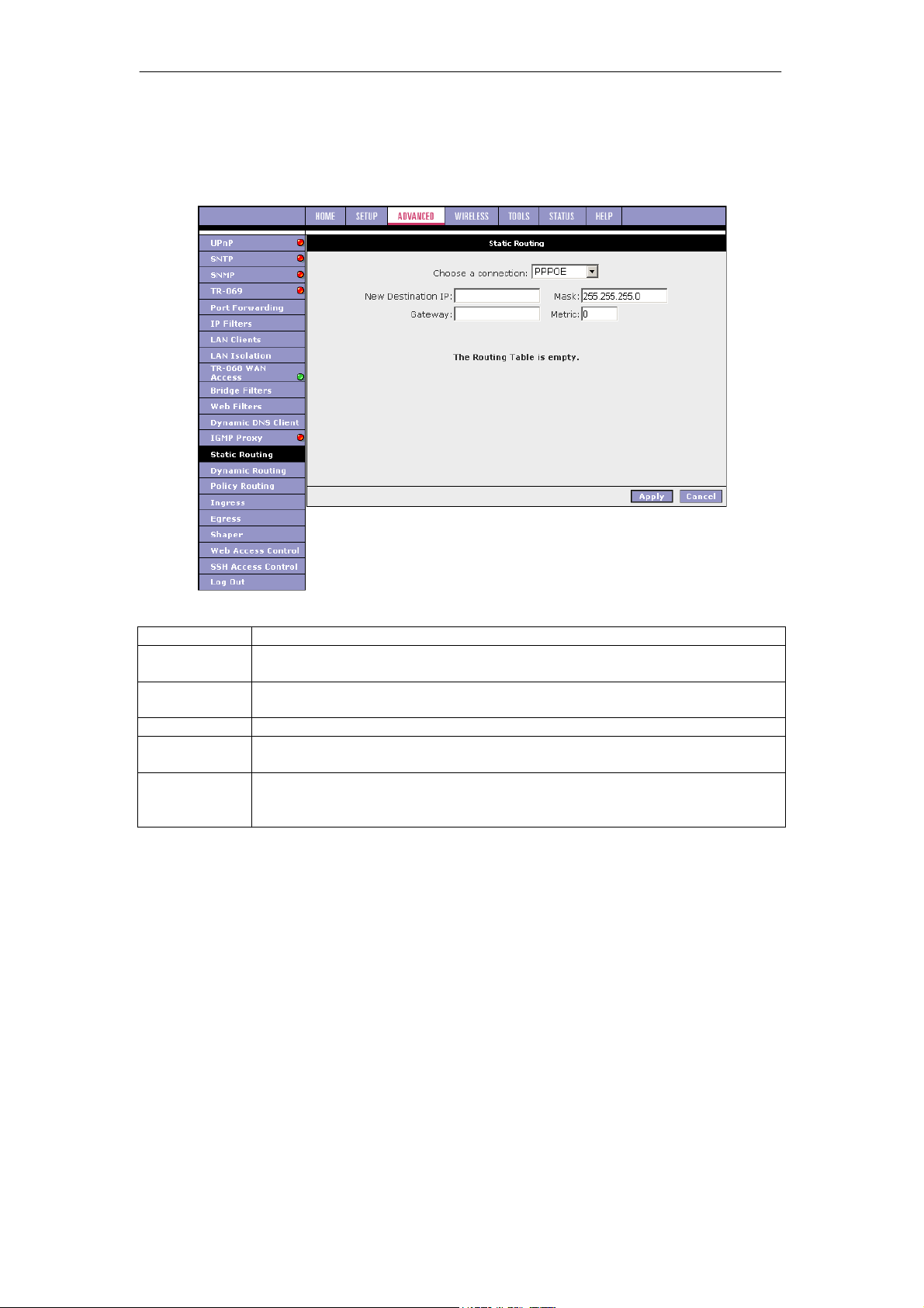
SOHOSpeed ADSL2/2+ Ethernet/Wireless Gateway User’s Manual
3.7.14 Static Routing
The Static Routing page enables you to define routes for specific subnets on the WAN/LAN
side. The SOHOSpeed allows you to manually program the SOHOSpeed's routing table. Up
to 16 static routes can be added.
Field Description
Field
Select a
Connection
New
Destination IP
Mask
Gateway
Metric
Suppose you have a network like the one shown in figure below. In your LAN, you have an
Gateway (192.168.1.1) and three stations connected to it (192.168.1.x). A subnet is added to
your LAN group by adding a second router (192.168.1.5/ 10.0.0.1) with four stations (10.0.0.x)
connected to it. The four stations in the subnet cannot receive packets unless they are added
to the routing table of your SOHOSpeed. You can add each individual station to the routing
table using the Static Routing page, or more easily, you can add the whole subnet in one
entry.
The procedure below explains how to add the subnet to the SOHOSpeed routing table.
Definition/Description
Select the LAN group or WAN connection to which a static routing subnet is
to be applied.
The network IP address of the subnet. (You can also enter the IP address of
each individual station in the subnet).
The network mask of the destination subnet.
The IP address of the next hop through which traffic will flow towards the
destination subnet.
Defines the number of hops the between network nodes that data packets
travel. The default value is 0, which means that the subnet is directly one hop
away on the local LAN network.
72
Page 74
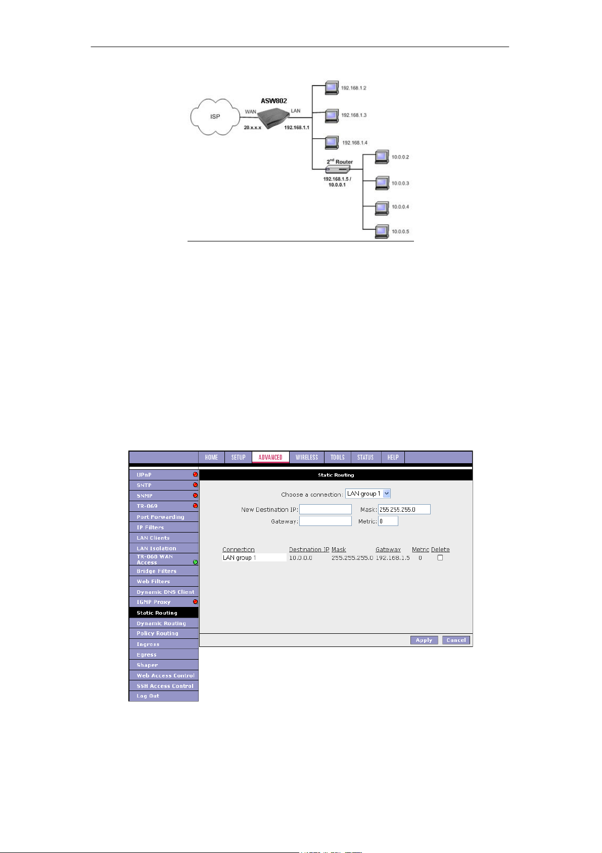
SOHOSpeed ADSL2/2+ Ethernet/Wireless Gateway User’s Manual
1. From the Choose a connection drop-down menu, select your LAN connection LAN
Group 1.
2. Enter or leave the default entry for the following parameters:
z New Destination IP: 10.0.0.0 (the network IP address of the subnet)
z Mask: 255.255.255.0 (the subnet mask)
z Gateway: 192.168.1.5 (the LAN-side IP address of the second router, through
which the stations in the subnet access the network)
z Metric: 0
You are telling the SOHOSpeed that a new subnet with an IP of 10.0.0.0 and a netmask
of 255.255.255.0 has been added and can access the SOHOSpeed via station
192.168.1.5.
The metric is 0 since the subnet is one level down on the LAN.
3. Click Apply to temporarily activate the settings.
You have added the subnet to the routing table. The four stations in the subnet can
receive packets from the WAN.
Note: You can add up to 16 entries. You can also delete any entry using the Delete checkbox.
4. Click Apply again when you finish making all the changes.
Note: The changes take effect when you click Apply; however, if the SOHOSpeed
configuration is not saved, these changes will be lost upon SOHOSpeed reboot.
73
Page 75
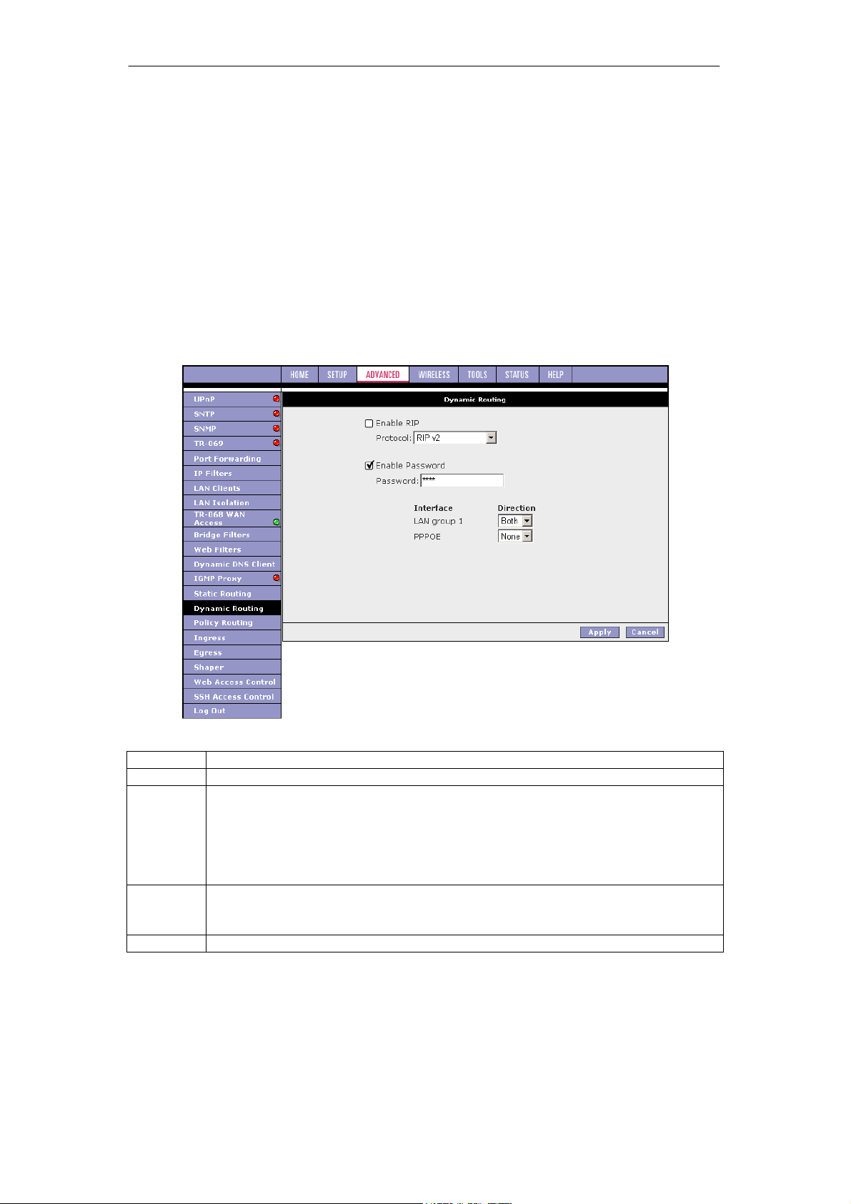
SOHOSpeed ADSL2/2+ Ethernet/Wireless Gateway User’s Manual
5. To make the change permanent, click Tools at the top of the page and select System
Commands.
6. At the System Commands page, click Save All.
3.7.15 Dynamic Routing
The dynamic routing feature enables the SOHOSpeed to dynamically define routes for WAN
and LAN subnets. Dynamic routing uses routing information protocol (RIP) for exchanging
routing information with other routers in the network. It is supported across both WAN and
LAN interfaces. Any RIP-enabled router sends out automatic update packets containing its
own routing table on a periodic basis (every 30 secs). Similarly, it accepts such periodic
updates from other routers and adds, deletes, or modifies routes in its own routing table
accordingly. The router is also expected to receive requests for its routing table and respond
accordingly. Use the Dynamic Routing page to define dynamic routing routes for the available
interfaces.
Field Description
Field Definition/Description
Enable RIP
Protocol
Enable
Password
Password
Enables/disables RIP.
The following three RIP versions are available:
z RIP v1 (UDP protocol)
z RIP v2 (multicast protocol)
z RIP v1 compatible (UDP protocol with multicast format)
Note: Routers using RIP v1 or RIP v1-compatible protocol can talk to each other,
but not to routers using RIP v2 protocol.
This is an optional field. RIP version v2 compatibility allows you to provide simple
plain-text password-based authentication to RIP packets.
This field is disabled if RIP v1 protocol is selected.
The password can be up to 16 characters long.
74
Page 76
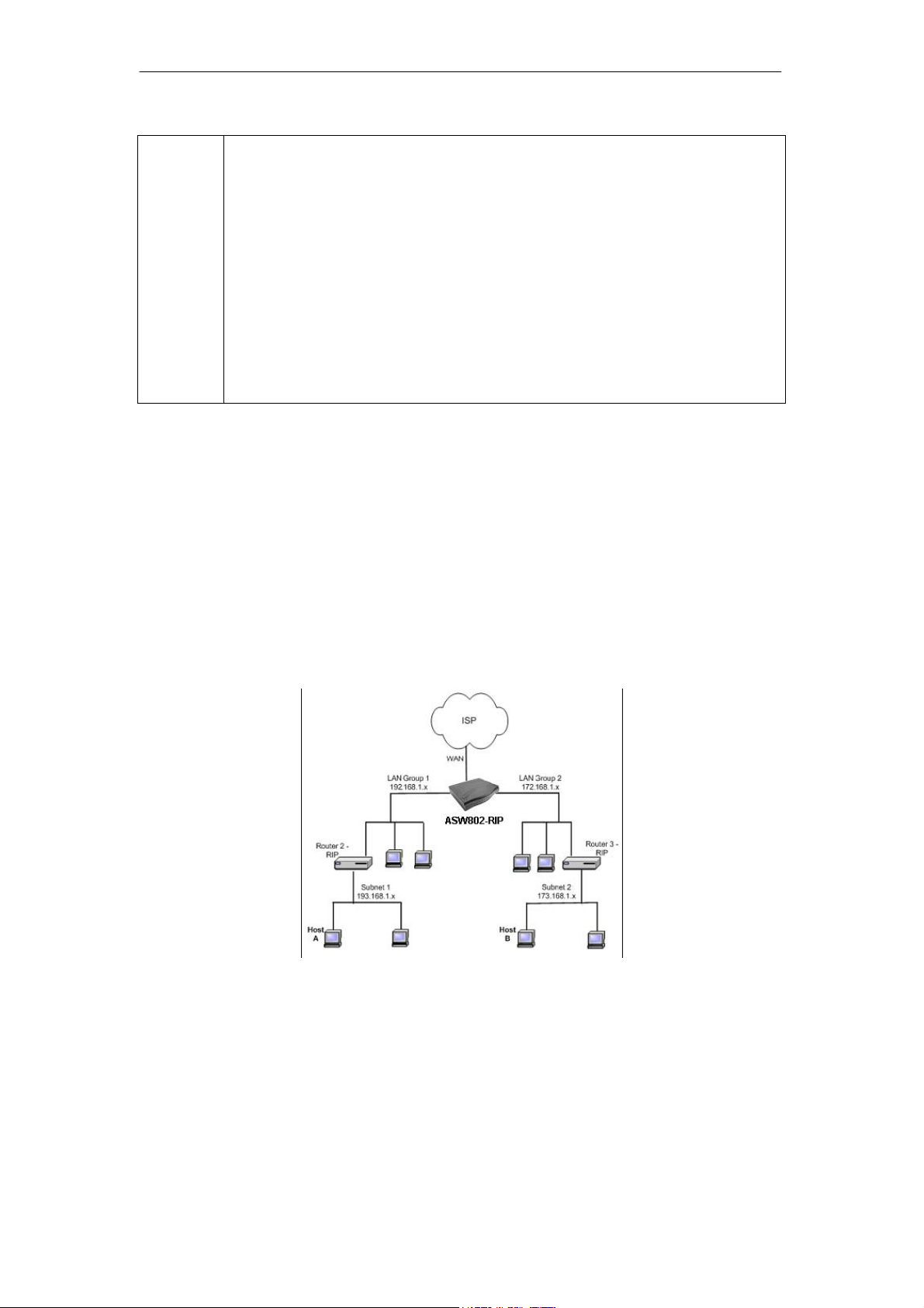
SOHOSpeed ADSL2/2+ Ethernet/Wireless Gateway User’s Manual
Direction
To demonstrate the use of the dynamic routing feature, consider an expanded version of the
network used in the static routing example in ‘‘Static Routing Page’’. As shown in figure below,
you have a network with two LAN connections (192.168.1.x and 172.168.1.x), and each has a
router and a subnet.
How can host A in subnet 1 (193.168.1.x) talk to host B in subnet 2 (173.168.1.x)? You have
two options:
z As previously demonstrated in Procedure 14, using the static routing feature, you can
add both subnets to the routing table using the Static Routing page (two separate
entries).
z You can enable dynamic routing on all routers without having to manually enter the
individual routes. Keep in mind that you need to enable all routers on this network and
they should use the same protocol to be able to communicate with each other.
Procedure 15 shows you how to enable and configure the dynamic routing feature on
your SOHOSpeed.
Normally when RIP is enabled on a router, it dynamically learns/provides routes
on all its configured interfaces. This parameter allows you to select the interfaces
on which RIP is expected to learn and distribute routing information. This feature
allows you to control how and which routes get distributed through the network.
For example, by selecting In only mode, routes to private LAN networks are
prevented from being sent over to the WAN-side router. The following four
direction options are available:
z Both: Receive updates on the interface and also send its routing table to
other routers connected to that interface.
z In: Receive routing updates from other routers connected to that interface
but do NOT send routing updates on that interface.
z Out: Send routing updates but do NOT receive updates on this interface
from the other routers connected to that interface.
z None: Ignore this interface and do not send or receive routing updates
through this interface.
1. Check Enable RIP.
2. Select the RIP Protocol RIP v2 for training purpose.
The Enable Password field is enabled.
Note: The same RIP protocol should be used to enable dynamic routing on all routers
on the network.
3. Check Enable Password and enter a password.
This is an optional field for additional security.
4. For LAN group 1 and LAN group 2, leave Both checked in the Direction field.
5. Click Apply to temporarily activate the settings.
Notice you did not need to enter the subnet IP, mask, or gateway when using the
75
Page 77
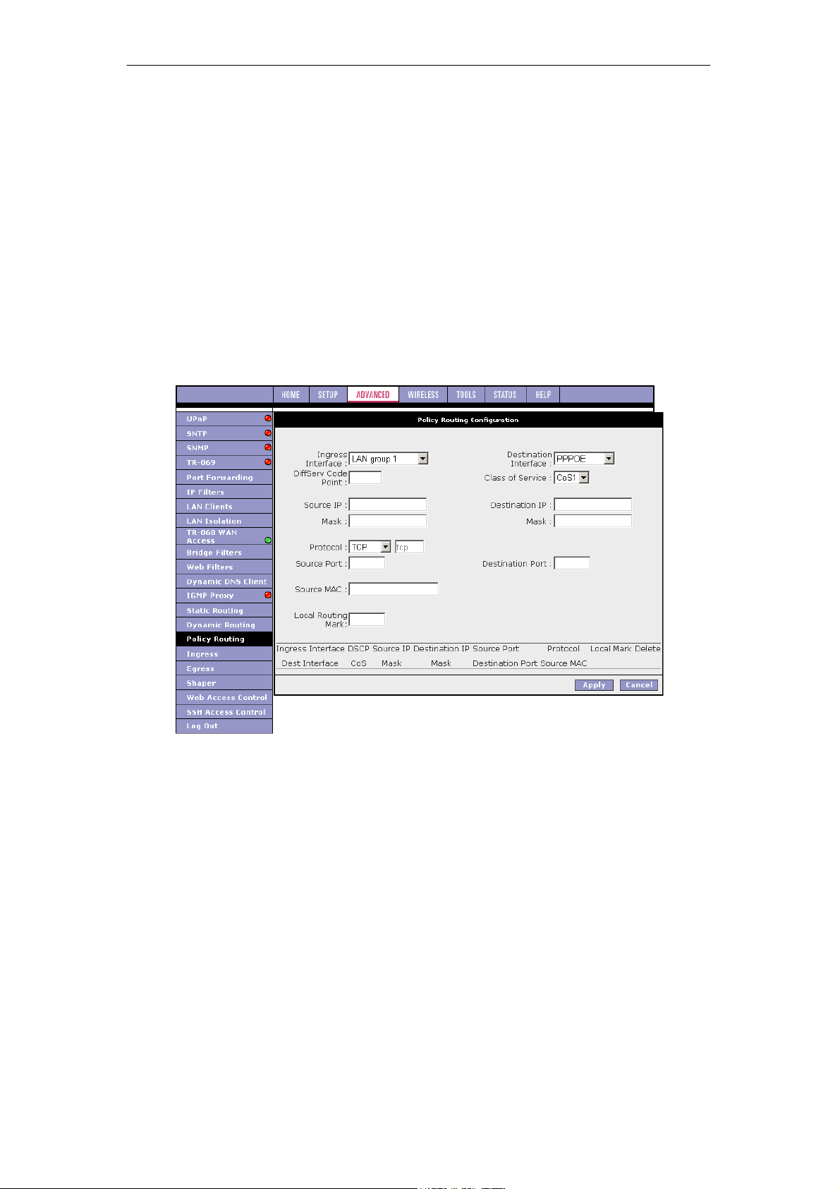
SOHOSpeed ADSL2/2+ Ethernet/Wireless Gateway User’s Manual
dynamic routing feature. The SOHOSpeeds can receive and transmit routing information
and add it to their own routing tables.
You also need to enable dynamic routing on routers 2 and 3.
6. Click Apply again when you finish making all the changes.
Note: The changes take effect when you click Apply; however, if the SOHOSpeed
configuration is not saved, these changes will be lost upon SOHOSpeed reboot.
7. To make the change permanent, click Tools at the top of the page and select System
Commands.
8. At the System Commands page, click Save All.
3.7.16 Policy Routing
The Policy Routing Configuration page is accessed by selecting Policy Routing on the
Advanced home page. This page enables you to configure policy routing and QoS. The policy
routing configuration is discussed as follows. The QoS configuration is discussed in ‘‘Ingress
Payload Database Configuration’’.
76
Page 78

SOHOSpeed ADSL2/2+ Ethernet/Wireless Gateway User’s Manual
The table below describes the Policy Routing Configuration page settings.
Field Description
Field Definition/Description
Ingress Interface
The incoming traffic interface for a Policy Routing rule. Selections
include LAN interfaces, WAN interfaces, Locally generated (traffic),
and not applicable. Examples of Locally generated traffic are: voice
packets, packets generated by applications such as DNS, DHCP, etc.
Destination
Interface
DiffServ Code Point
The outgoing traffic interfaces for a Policy Routing rule. Selections
include LAN Interfaces and WAN interfaces.
The DiffServ code point (DSCP) field value ranges from 1 to 255. This
field cannot be configured alone, addtional fields like IP, Source MAC,
and/or Ingress Interface should be configured.
Class of Service
The selections are (in the order of priority): CoS1, CoS2, CoS3, CoS4,
CoS5, CoS6, and N/A.
Source IP
Mask
The IP address of the traffic source.
The source IP netmask. This field is required if the source IP has been
entered.
Destination IP
Mask
The IP address of the traffic destination.
The netmask of the destination. This field is required if the destination
IP has been entered.
Protocol
The selections are TCP, UDP, ICMP, Specify, and none. If you choose
Specify, you need to enter the protocol number in the box next to the
Protocol field.
This field cannot be configured alone, addtional fields like IP, Source
MAC, and/or Ingress Interface should be configured.
This field is also required if the source port or destination port has been
entered.
Source Port
The source protocol port. You cannot configure this field without
entering the protocol first.
Destination Port
The destination protocol port or port range. You cannot configure this
field without entering the protocol first.
Source MAC
Local Routing Mark
The MAC address of the traffic source.
This field is enabled only when Locally Generated is selected in the
Ingress Interface field. The mark for DNS traffic generated by different
applications are described below:
z Dynamic DNS: 0xE1
z Dynamic Proxy: 0xE2
z Web Server: 0xE3
z MSNTP: 0xE4
z DHCP Server: 0xE5
z IPtables Utility: 0xE6
z PPP Deamon: 0xE7
z IP Route: 0xE8
z ATM Library: 0xE9
z NET Tools: 0xEA
z RIP: 0xEB
z RIP v2: 0xEC
z UPNP: 0xEE
z Busybox Utility: 0xEF
z Configuration Manager: 0xF0
z DropBear Utility: 0xF1
z Voice: 0
Note: Wildcard (*) entries are allowed for IP Address/Netmask and Port range fields.
77
Page 79
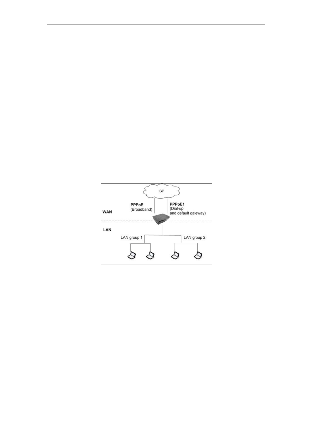
SOHOSpeed ADSL2/2+ Ethernet/Wireless Gateway User’s Manual
Currently routing algorithms make decision based on destination address, i.e., only
Destination IP address and subnet mask is supported. The Policy Routing page enables you
to route packets on the basis of various fields in the packet. The following fields can be
configured for Policy Routing:
z Destination IP address/mask
z Source IP address/mask
z Source MAC address
z Protocol (TCP, UDP, ICMP, etc)
z Source port
z Destination port
z Incoming interface
z DSCP
Example: Traffic Segregation
In the first example, we will use the Policy Routing Configuration page to configure traffic
segregation. As shown in figure below, your SOHOSpeed has the following configuration:
z Two WAN connection: PPPoE (broadband connection) and PPPoE1 (dial-up and default
gateway).
z Two LAN groups: LAN group 1 and LAN group 2
z Two computers in LAN group 1
z Two computers in LAN group 2
Goal: You want to reserve PPPoE for use by LAN group 1 computers only.
To create PR rule:
1. In the Ingress field, select LAN Group 1.
2. In the Destination Interface field, select PPPoE.
3. In the Class of Service field, select N/A.
4. In the Protocol field, leave the default selection None.
This is to select all protocols.
5. Click Apply to temporarily activate the settings on the page.
The first rule is created. Voice traffic from LAN group 1 will go out on PPPoE.
6. In the Ingress field, select PPPoE.
7. In the Destination Interface field, select LAN Group 1.
8. In the Class of Service field, select N/A.
9. In the Protocol field, leave the default selection None.
This is to select all protocols.
10. Click Apply to temporarily activate the settings on the page.
Packets arriving into LAN group 1 will come from PPPoE. The rule is generated at the
bottom of the page.
78
Page 80
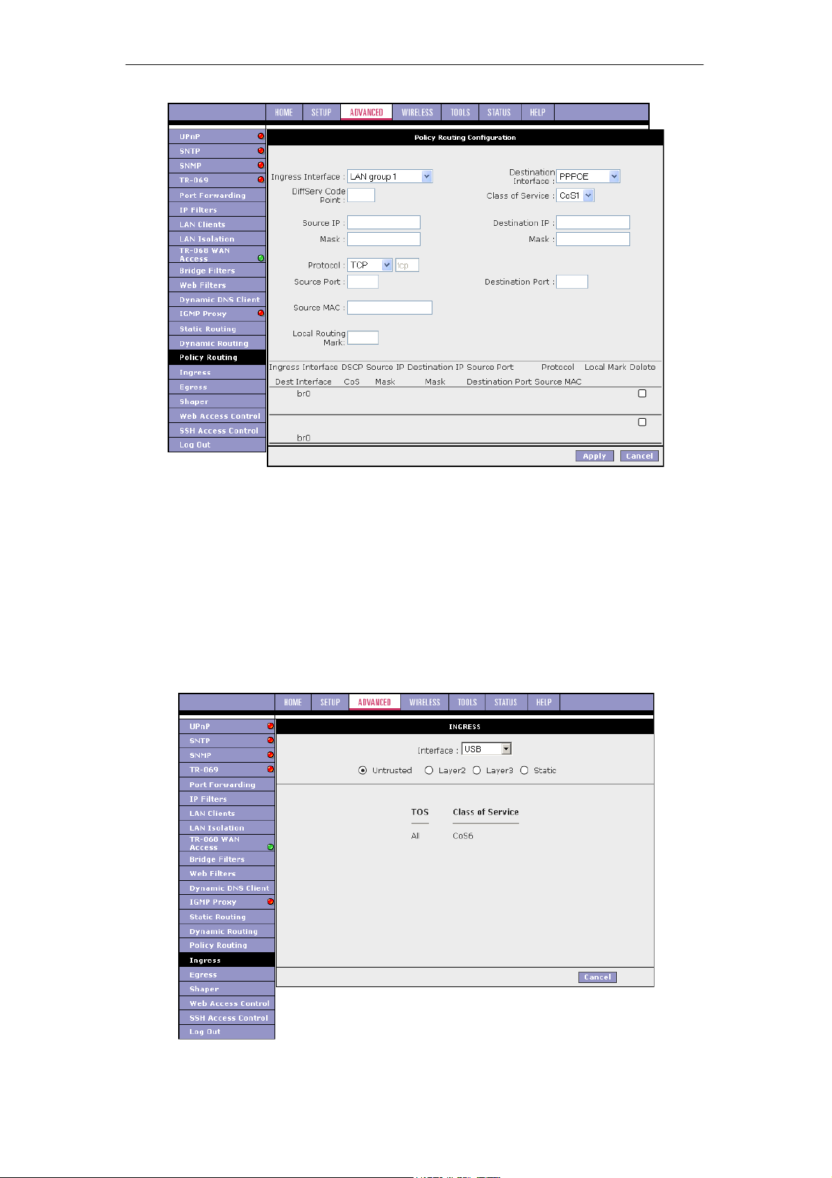
SOHOSpeed ADSL2/2+ Ethernet/Wireless Gateway User’s Manual
Note: The changes take effect when you click Apply; however, if SOHOSpeed configuration
is not saved, these changes will be lost upon SOHOSpeed reboot.
11. To make the change permanent, click Tools at the top of the page and select System
Commands.
12. At the System Commands page, click Save All.
3.7.17 Ingress
The Ingress page enables you to configure QoS for packets as soon as they come into the
SOHOSpeed. The domain mappings are converted to CoS (the common language) so that
the priority marking is carried over.
79
Page 81
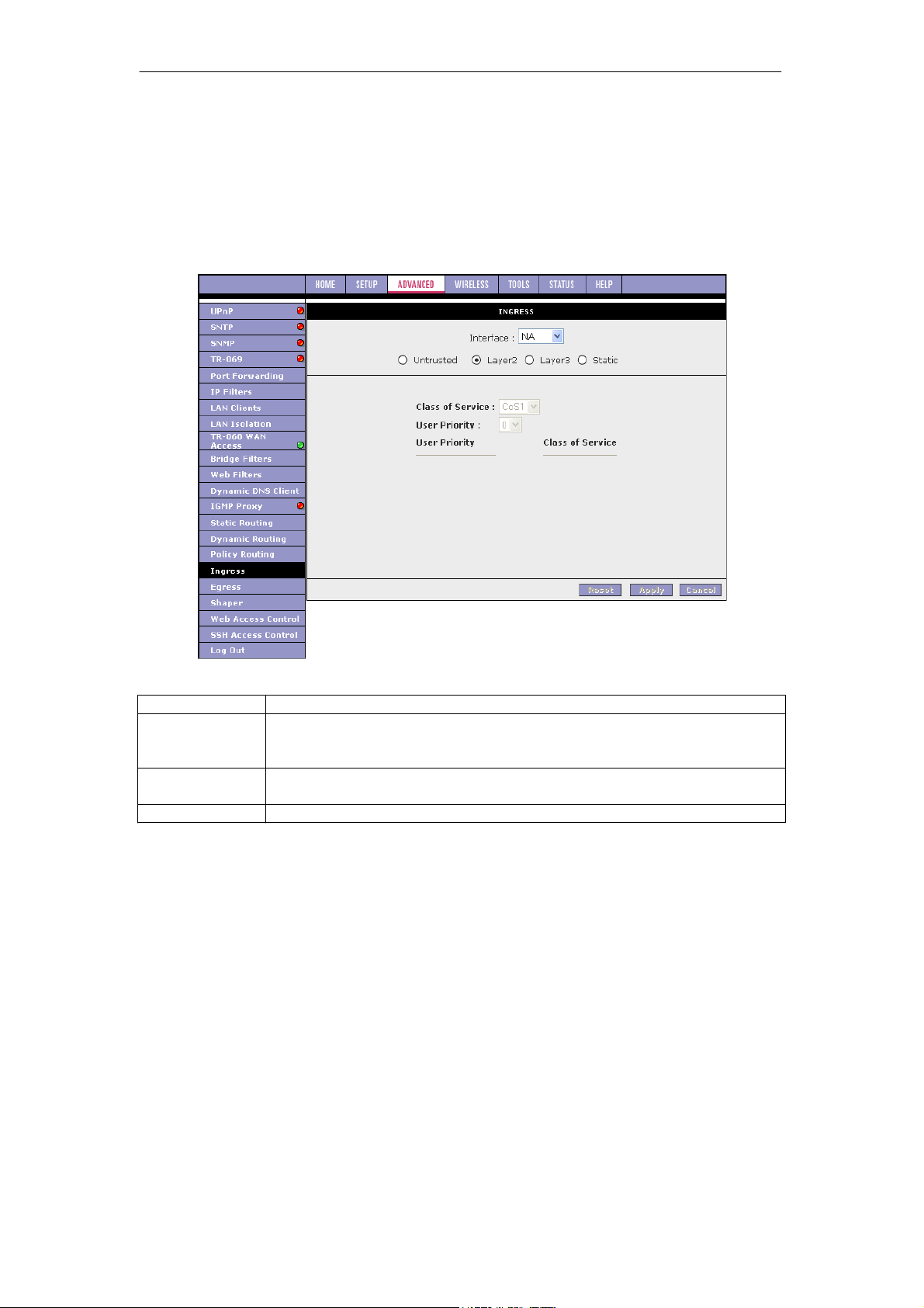
SOHOSpeed ADSL2/2+ Ethernet/Wireless Gateway User’s Manual
There are four modes that are discussed below:
z Ingress Untrusted Mode
Untrusted is the default Ingress page setting for all interfaces. In this mode, no domain
mapping is honoured in the SOHOSpeed. All packets are treated as CoS6 (best effort)
as shown in previous figure.
z Layer2 enables you to map an incoming packet with VLAN priority to CoS. This feature
is only configurable on the WAN interfaces as VLAN is only supported on the WAN side
in the current software release.
Field Description
Field Definition/Description
Interface
Class of Service
User Priority
Follow the procedure below to configure Ingress Layer 2 QoS settings:
Select the WAN interface here to configure the CoS for incoming traffic.
Only WAN interface can be selected as VLAN is currently supported only
on the WAN side.
The selections are (in the order of descending priority): CoS1, CoS2,
CoS3, CoS4, CoS5, and CoS6.
The selections are 0, 1, 2, 3, 4, 5, 6, 7.
1. From Interface drop-down box, select PPPoE1.
You are configuring QoS on this WAN interface.
2. Select CoS1 in Class of Service and 5 in Priority Bits.
Any packets with priority marking 5 is mapped to CoS1, the highest priority that is
normally given to the voice packets.
3. Click Apply to temporarily activate the settings.
4. Select CoS2 in the Class of Service field and 1 in the Priority Bits field.
Any packets that have a priority bits of 1 is mapped to CoS2, which is the second
highest priority. This is given to the high priority packets such as video.
5. Click Apply to temporarily activate the settings.
Note: The changes take effect when you click Apply; however, if the SOHOSpeed
configuration is not saved, these changes will be lost upon SOHOSpeed reboot.
6. Repeat step 2-5 to add more rules to PPPoE1.
Up to eight rules can be configured for each interface.
Note: Any priority bits that have not been mapped to a CoS default to CoS6, the lowest
priority.
80
Page 82
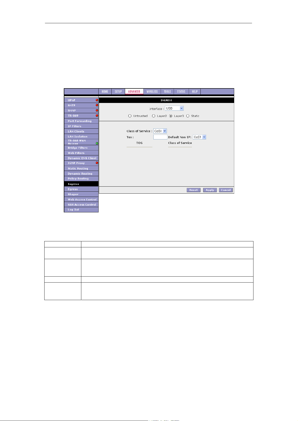
SOHOSpeed ADSL2/2+ Ethernet/Wireless Gateway User’s Manual
7. Repeat step 1-6 to create rules to another WAN interface.
Note: Any WAN interface that is not configured has the default Untrusted mode.
8. To make the change permanent, click Tools at the top of the page and select System
Commands.
9. At the System Commands page, click Save All.
z Ingress Layer 3 Configuration
The Layer 3 page allows you to map ToS bits of incoming packets from the IP network to CoS
for each WAN/LAN interface.
Field Description
Field Definition/Description
Interface
Class of
Service
ToS
Default Non IP
For both WAN and LAN interfaces, you can configure QoS for layer 3 (IP)
data traffic.
This CoS field allows you to map incoming layer 3 WAN/LAN packets to one
of the following CoS (in the order of descending priority): CoS1, CoS2, CoS3,
CoS4, CoS5, and CoS6.
The type of service field takes values from 0 to 255.
A static CoS can be assigned to all layer 3 incoming packets (per interface)
that do not have an IP header, such as PPP control packets and ARP
packets. The default is CoS1 (recommended).
1. From Interface drop-down box, select LAN Group 1.
You are configuring QoS on this interface.
2. Select CoS1 in Class of Service and enter 22 in Type of Service (ToS).
Any incoming packet from LAN Group 1 (layer 3) with a ToS of 22 is mapped to CoS1,
the highest priority, which is normally given to the voice packets.
3. Leave the default value CoS1 in Default Non-IP.
Any incoming packet from LAN Group 1 without an IP is mapped to CoS1, the highest
priority.
4. Click Apply to temporarily activate the settings.
Note: The changes take effect when you click Apply; however, if SOHOSpeed
configuration is not saved, these changes will be lost upon SOHOSpeed reboot.
5. Repeat step 2-4 to add more rules to LAN Group 1.
81
Page 83
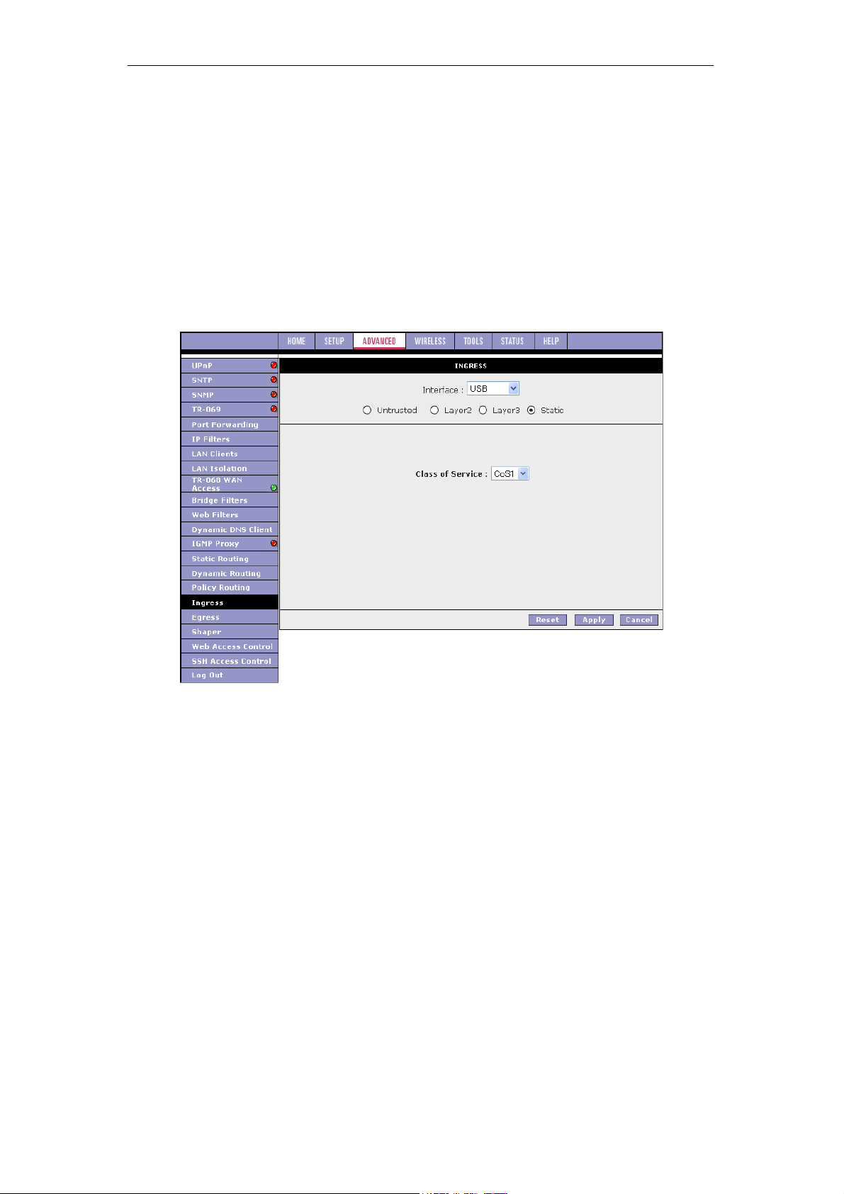
SOHOSpeed ADSL2/2+ Ethernet/Wireless Gateway User’s Manual
Up to 255 rules can be configured for each interface.
Note: Any ToS that have not been mapped to a CoS is treated as CoS6, the lowest
priority.
6. Repeat step 1-5 to create rules to another WAN/LAN interface.
Note: Any WAN/LAN interface that is not configured has the default Untrusted mode.
7. To make the change permanent, click Tools at the top of the page and select System
Commands.
8. At the System Commands page, click Save All.
z Ingress Static Configuration
The Ingress - Static page enables you to configure a static CoS for all packets received on a
WAN or LAN interface.
Follow the procedure below to configure Ingress static QoS settings:
1. At the Interface drop-down box, select USB.
You are configuring QoS on this interface only. Any WAN/LAN interface that is not
configured has the default Untrusted mode.
2. Select CoS1 in Class of Service.
All incoming traffic from the USB interface receives CoS1, the highest priority.
3. Click Apply to temporarily activate the settings.
Note: The changes take effect when you click Apply; however, if the SOHOSpeed
configuration is not saved, these changes will be lost upon SOHOSpeed reboot.
4. To make the change permanent, click Tools at the top of the page and select System
Commands.
5. At the System Commands page, click Save All.
82
Page 84
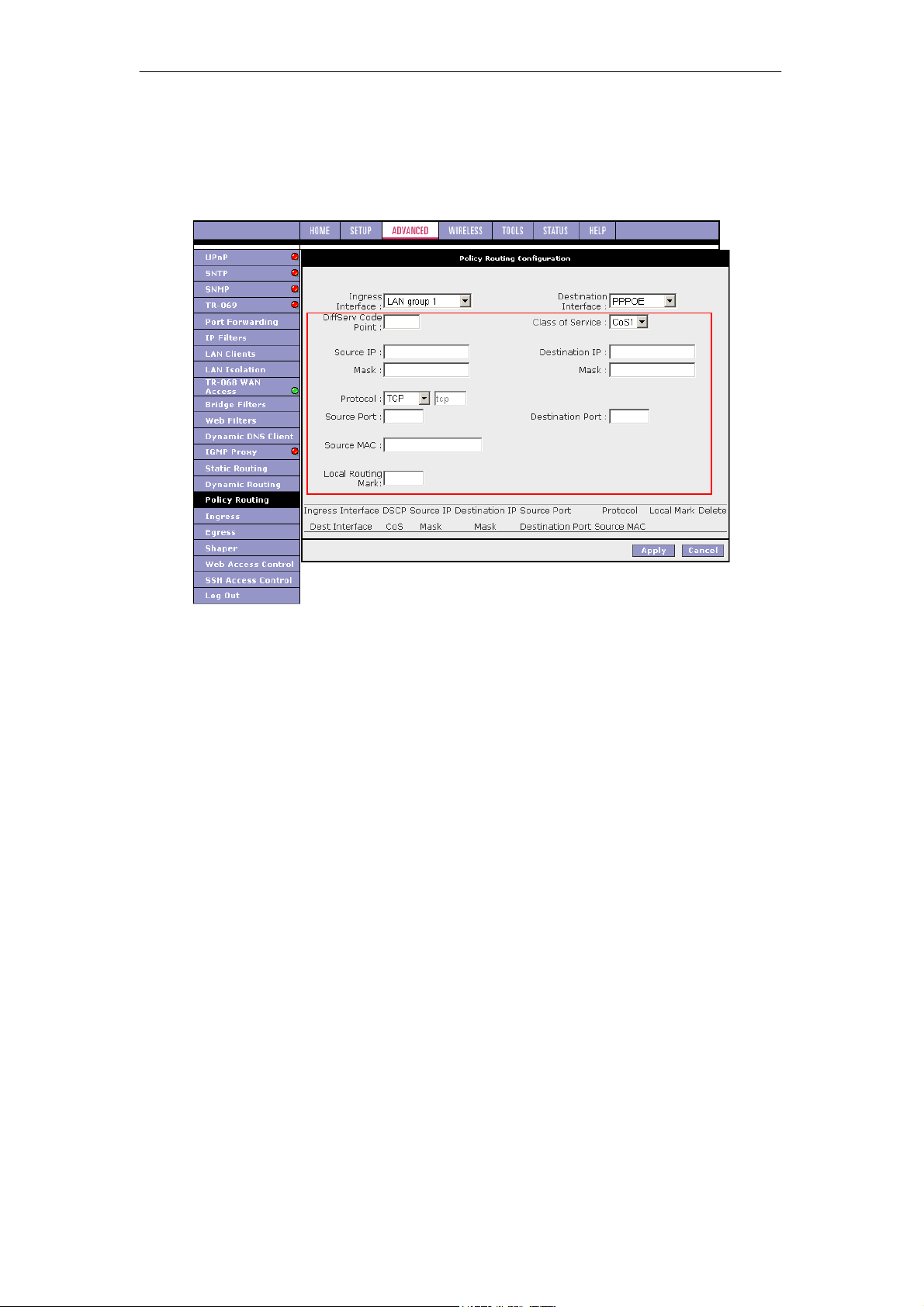
SOHOSpeed ADSL2/2+ Ethernet/Wireless Gateway User’s Manual
Ingress Payload Database Configuration
The Policy Routing Configuration page is accessed by selecting Policy Routing on the
Advanced home page. This page enables you to configure QoS payload database and policy
routing. The QoS payload database configuration will be discussed here. The policy routing
configuration will be discussed in ‘‘Policy Routing’’.
QoS can be configured in the Ingress and Egress pages on a per interface basis. The Policy
Routing page enables you to classify packets on the basis of various fields in the packet.
The following fields can be configured for QoS:
z CoS
z Source IP address/mask
z Destination IP address/mask
z Protocol
z Source port
z Destination port
z Source Mac address
83
Page 85
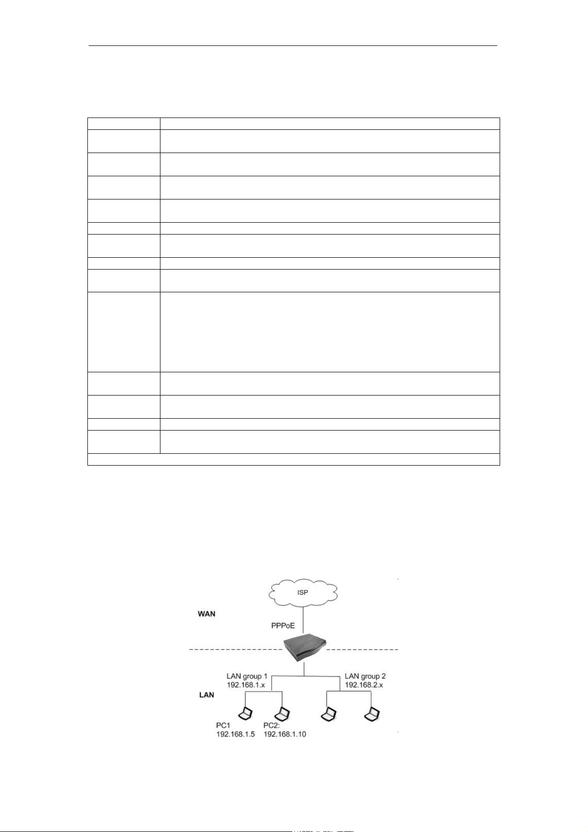
SOHOSpeed ADSL2/2+ Ethernet/Wireless Gateway User’s Manual
You can configure any or all field as needed. The table below describes the QoS-related
fields on the Policy Routing Configuration page.
Field Description
Field Definition/Description
Ingress
Interface
Destination
Interface
DiffServ Code
Point
Class of
Service
Source IP
Mask
This field is applicable for policy routing configuration only and will be
discussed in ‘‘Policy Routing’’.
This field is applicable for policy routing configuration only and will be
discussed in ‘‘Policy Routing’’.
This field is applicable for policy routing configuration only and will be
discussed in ‘‘Policy Routing’’.
The selections are (in the order of priority): CoS1, CoS2, CoS3, CoS4, CoS5,
CoS6, and N/A.
The IP address of the traffic source.
The source IP netmask. This field is required if the source IP has been
entered.
Destination IP
Mask
The IP address of the traffic destination.
The netmask of the destination. This field is required if the destination IP has
been entered.
Protocol
The selections are TCP, UDP, ICMP, Specify, and none. If you choose
Specify, you need to enter the protocol number in the box next to the
Protocol field.
This field cannot be configured alone, additional fields like IP and/or Source
MAC should be configured.
This field is also required if the source port or destination port has been
entered.
Source Port
The source protocol port. You cannot configure this field without entering the
protocol first.
Destination
Port
Source MAC
Local Routing
Mark
The destination protocol port. You cannot configure this field without entering
the protocol first.
The MAC address of the traffic source.
This field is applicable for policy routing configuration only and will be
discussed in ‘‘Policy Routing’’.
Note: Wildcard (*) entries are allowed for IP Address/Netmask and Port range fields.
Let’s configure QoS using the Policy Routing Configuration page. In the figure below, your
SOHOSpeed has the following configuration:
z WAN connection: PPPoE (default gateway).
z Two LAN groups: LAN group 1 and LAN group 2
z Two PCs in LAN group 1. You use PC 1 (192.168.1.5) to download movie and PC 2
(192.168.1.10) to surf the Internet.
Goal: You want to give priority to PC 1 traffic over PC 2 traffic.
84
Page 86
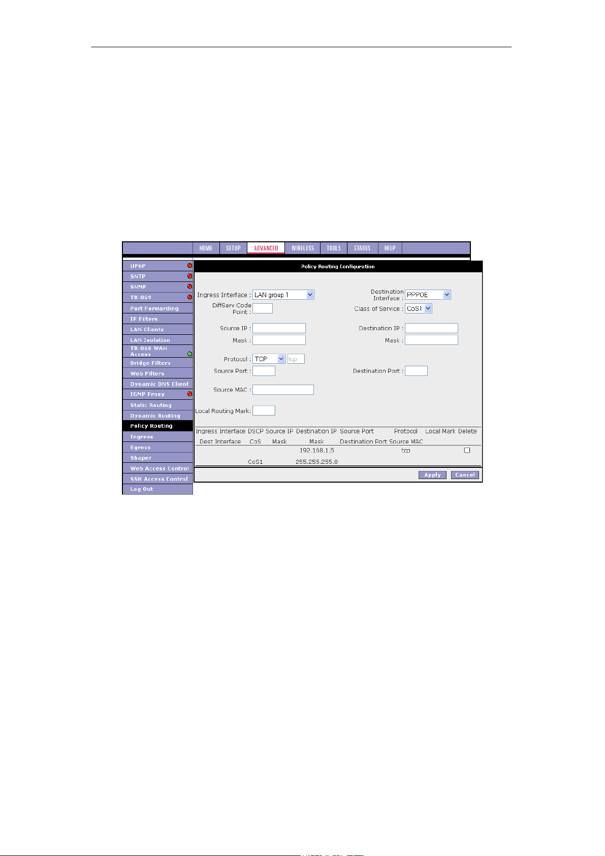
SOHOSpeed ADSL2/2+ Ethernet/Wireless Gateway User’s Manual
To configure the QoS rule:
1. In the Ingress field, select not applicable.
The field is applicable for policy routing only.
2. In the Destination Interface field, select not applicable.
The field is applicable for policy routing only.
3. In the Class of Service field, leave the default CoS1.
4. In the Destination IP field, enter 192.168.1.5.
5. In the Destination IP Mask field, enter 255.255.255.255.
6. In the Protocol field, leave the default selection TCP.
7. Click Apply to temporarily activate the settings on the page.
The rule is generated at the bottom of the page.
Note: The changes take effect when you click Apply; however, if SOHOSpeed
configuration is not saved, these changes will be lost upon SOHOSpeed reboot.
8. To make the change permanent, click Tools at the top of the page and select System
Commands.
9. At the System Commands page, click Save All.
85
Page 87
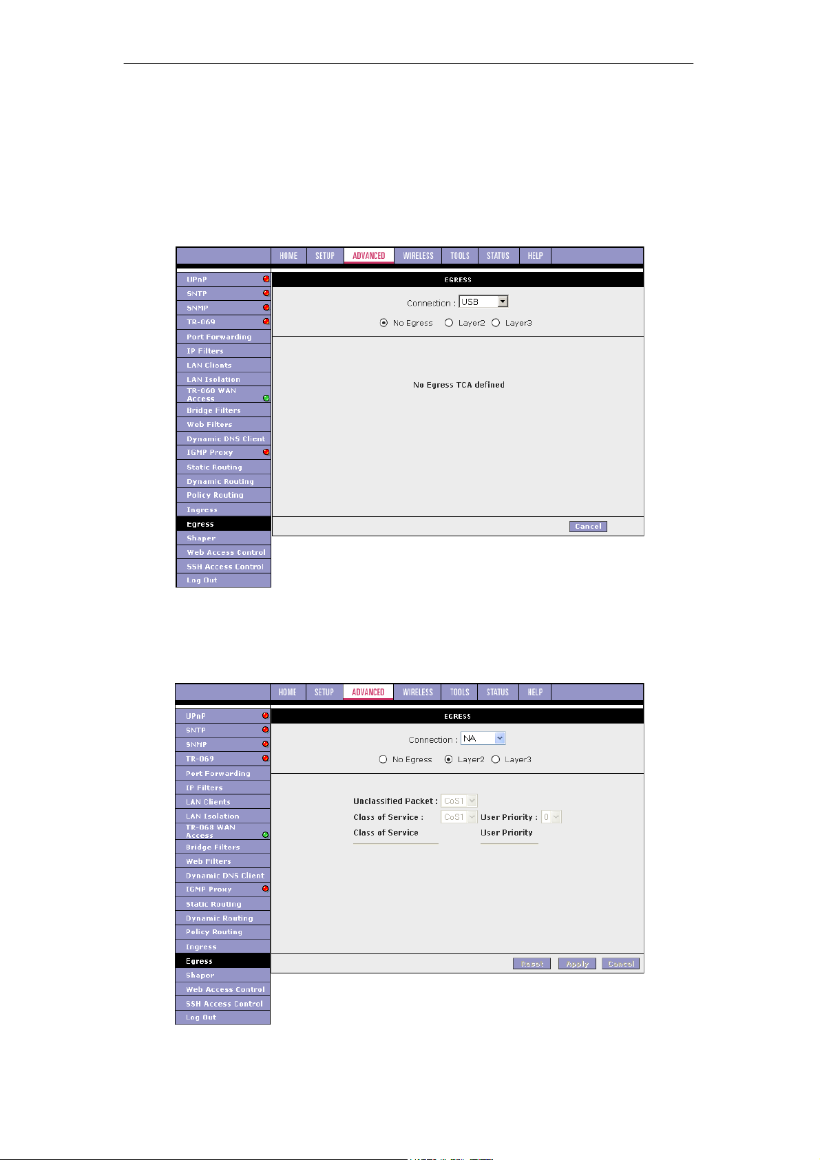
SOHOSpeed ADSL2/2+ Ethernet/Wireless Gateway User’s Manual
3.7.18 Egress
For packets going out of the SOHOSpeed, the marking (CoS) need to be translated to the
mappings understood by the network domains. The reverse CoS and domain mapping is
configured using the Egress page.
No Egress Mode
The default Egress page setting for all interfaces is No Egress. In this mode, the domain
mappings of the packets are untouched.
Egress Layer 2 Configuration
The Egress Layer 2 page enables you to map the CoS of an outgoing packet to user priority
bits, which is honoured by the VLAN network. Again, this feature is only configurable on the
WAN interfaces as VLAN is only supported on the WAN side in the current release.
86
Page 88
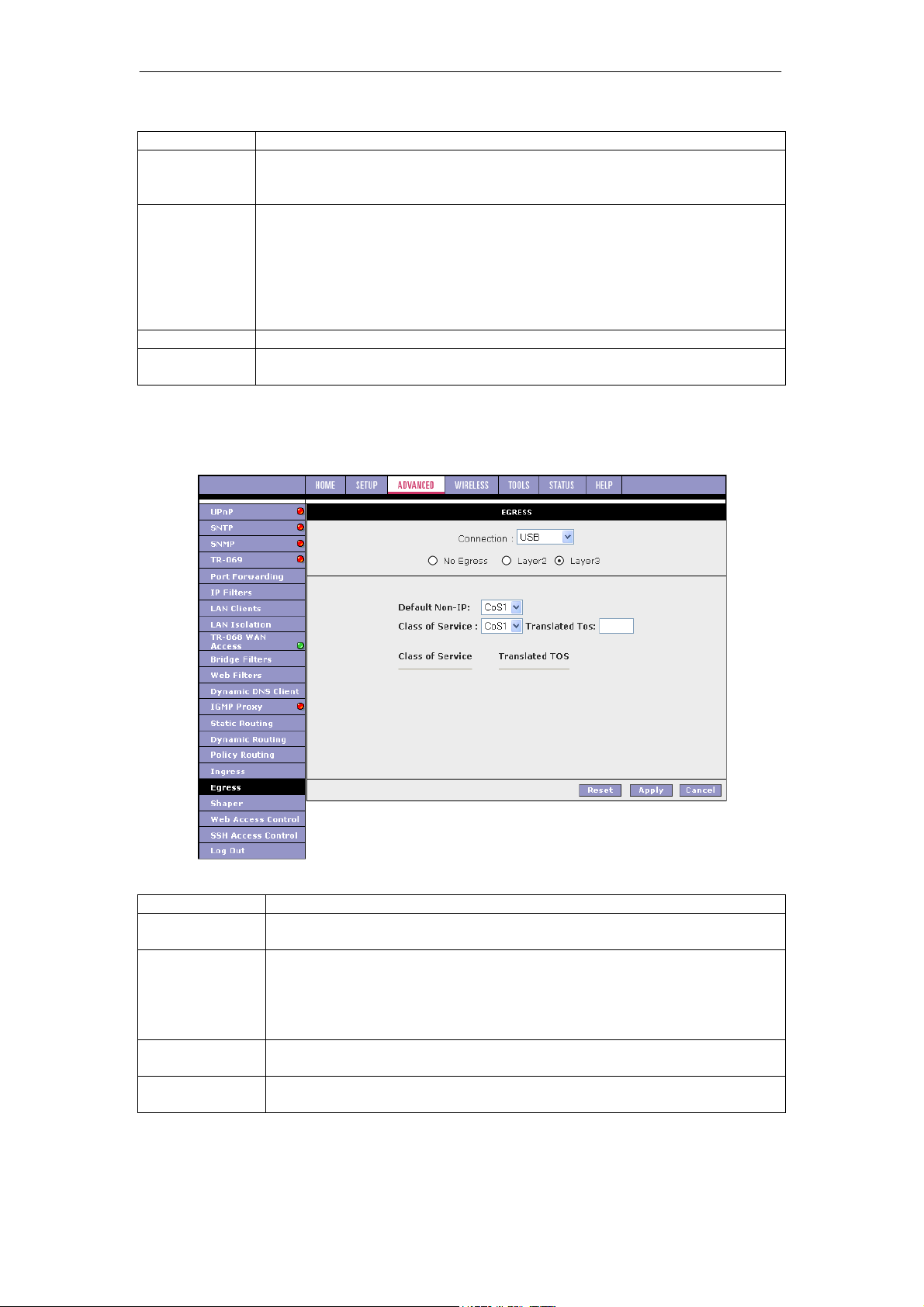
SOHOSpeed ADSL2/2+ Ethernet/Wireless Gateway User’s Manual
Field Description
Field Definition/Description
Interface
Select the WAN interface to configure the QoS for outgoing packets. LAN
interface can not be selected as VLAN is currently supported on the WAN
side only.
Unclassified
Packet
Some locally generated packets might not have been classified and thus do
not have a CoS value, such as PPP control packet and ARP packet. You
can define the CoS for all unclassified outgoing packets on layer 2 using this
field, which will then pick up the user priority bits based on the mapping rules
you create. The selections are (in the order of descending priority): CoS1,
CoS2, CoS3, CoS4, CoS5, and CoS6. The default value is CoS1
(recommended)
User Priority
Class of
Service
The selections are 0, 1, 2, 3, 4, 5, 6, 7.
The selections are (in the order of descending priority): CoS1, CoS2, CoS3,
CoS4, CoS5, and CoS6.
Egress Layer 3 Configuration
The Egress Layer 3 page enables you to map CoS to ToS so that the priority marking of
outgoing packets can be carried over to the IP network.
Egress - Layer 3 Page Descriptions
Field Definition/Description
Interface
Select the WAN/LAN interface here to configure the QoS for outgoing
traffic to the IP network.
Default Non-IP
Locally generated packets (such as ARP packets) do not have a CoS
marking. You can define the CoS for all unclassified outgoing packets on
layer 3 using this field. The selections are (in the order of descending
priority): CoS1, CoS2, CoS3, CoS4, CoS5, and CoS6. The default value is
CoS1 (recommended).
Translated ToS
The Type of Service field takes values from 1 to 255. The selections are 0,
1, 2, 3, 4, 5, 6, 7.
Class of Service
The selections are (in the order of descending priority): CoS1, CoS2,
CoS3, CoS4, CoS5, and CoS6.
87
Page 89
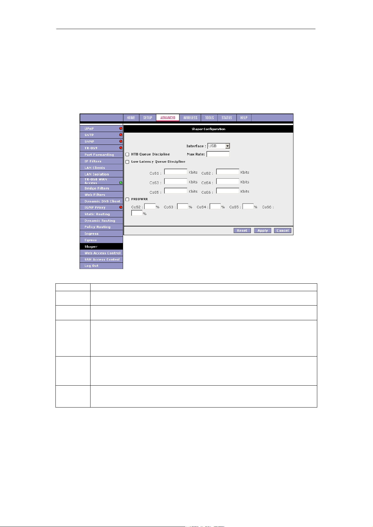
SOHOSpeed ADSL2/2+ Ethernet/Wireless Gateway User’s Manual
3.7.19 Shaper
The Shaper Configuration page is accessed by selecting Shaper on the Advanced main page.
Three shaper algorithms are supported:
z HTB
z Low Latency Queue Discipline
z PRIOWRR
Note: Egress TCA is required if shaper is configured for that interface.
Field Description
Field Definition/Description
Interface
Max Rate
HTB
Queue
Discipline
Low
Latency
Queue
Discipline
PRIOWRR
The selections are WAN/LAN interfaces except WLAN, which does not support
Shaper feature. This field needs to be selected before shaper configuration.
This field is applicable for the HTB Queue Discipline and Low Latency Queue
Discipline, both are rate-based shaping algorithms.
The hierachical token bucket queue discipline is a rate-based shaping algorithm.
This algorithm rate shapes the traffic of a class over a specific interface. All CoSx
traffic is assigned a specific rate to which data will be shaped to. For example: If
CoS1 is configured to 100Kbps then even if 300Kbps of CoS1 data is being
transmitted to the interface only 100Kbps will be sent out.
This is similar to the above algorithm except that CoS1 is not rate limited. So in
the example above CoS1 data is not rate limited to 100Kbps but instead all
300Kbps is transmitted. The side effect is that a misconfigured stream can
potentially take all bandwidth.
This is a priority based weighted round robin algorithm operating on CoS2-CoS6.
CoS1 queues have the highest priority and are not controlled by the WRR
algorithm.
88
Page 90
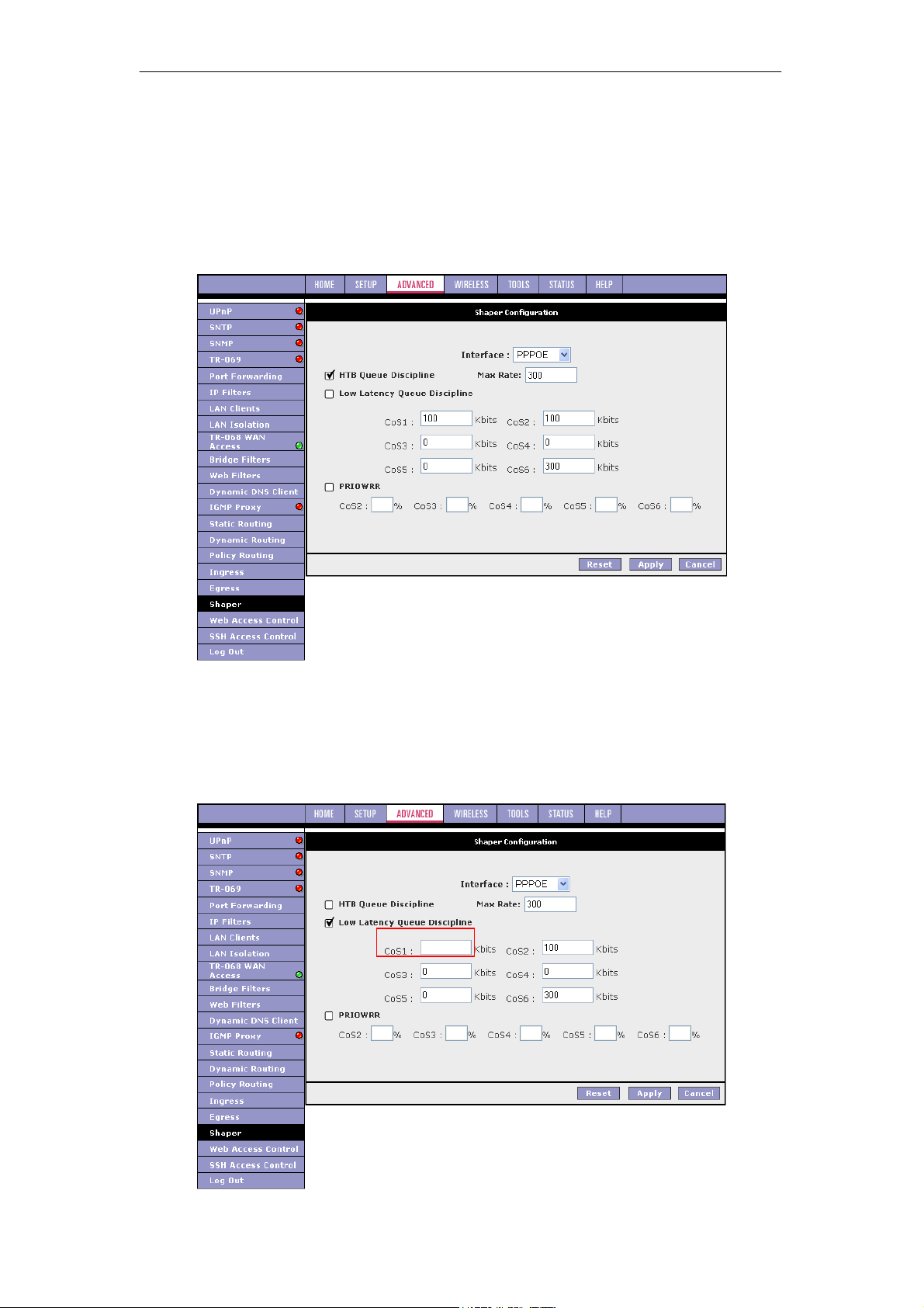
SOHOSpeed ADSL2/2+ Ethernet/Wireless Gateway User’s Manual
Of the three shaping algorithms available on the Shaper Configuration page, only one can be
enabled at a time. An example of each configuration is given as follows.
Example 1: HTB Queue Discipline Enabled
In the example below, HTB Queue Discipline is enabled. The PPPoE connection has a total
of 300 kbits of bandwidth, of which 100 kbits is given to CoS1 and another 100 kbits is given
to CoS2. When there is no CoS1 or CoS2 packets, CoS6 packets have the whole 300 kbits of
bandwidth.
Example 2: Low Latency Queue Discipline Enabled
In this second example, Low Latency Queue Discipline is enabled.
CoS1 is not rate controlled (hence the field is disabled). CoS2 takes 100 kbits when there is
no CoS1 packet. CoS6 has 300 kbits when there is no CoS1 or CoS2 packets. This is similar
to the HTB queue discipline as they are both rate-based algorithm, except that CoS1 is
handled differently.
89
Page 91
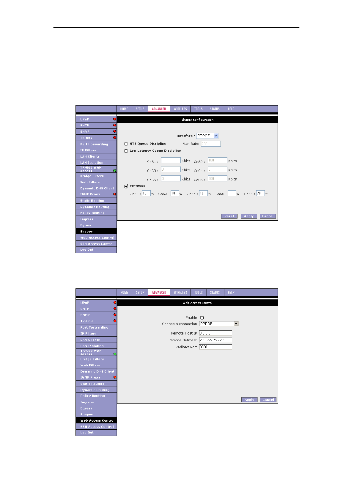
SOHOSpeed ADSL2/2+ Ethernet/Wireless Gateway User’s Manual
Example 3: PRIOWRR Enabled
In this third example, PRIOWRR is enabled. Since PRIOWRR operates only on the number of
packets being transmitted, the max rate field has been disabled. Only percentage can be
assigned to the CoS2 - CoS6. CoS1 is not rate controlled (hence the field is not displayed).
When there is no CoS1 packet, CoS2, CoS3, CoS4 each has 10 percent, and CoS6 has 70
percent. This is similarly to the Low Latency Queue discipline, except that one is packetbased, and the other is rate-based.
3.7.20 Web Access Control
The Web Access Control page allows you to access the SOHOSpeed remotely via the web
from the WAN side.
90
Page 92

SOHOSpeed ADSL2/2+ Ethernet/Wireless Gateway User’s Manual
If you want to access your SOHOSpeed at home from a remote location such as your office,
use the table below as a reference and follow the procedure below to configure your WAN IP
address.
1. Check Enable to enable the Web access control feature.
2. In the Choose a Connection field, leave the default WAN connection selected.
3. In the Remote Host IP field, enter the WAN-side IP address you will use to access your
SOHOSpeed (for example, 10.10.10.1).
4. In the Remote Netmask field, enter the netmask of your WAN-side IP address.
5. Enter a port number In the Redirect Port field (for example, 80).
6. Click Apply to temporarily activate the settings on the page.
This WAN address is added to the IP Access List. This allows you to access you
SOHOSpeed at home from a WAN IP (10.10.10.1) via Web.
Note: The changes take effect when you click Apply; however, if the SOHOSpeed
configuration is not saved, these changes will be lost upon SOHOSpeed reboot.
7. To make the change permanent, click Tools at the top of the page and select System
Commands.
8. At the System Commands page, click Save All.
9. To access your SOHOSpeed from the remote IP (10.10.10.1), enter the following in the
URL:
http(s)://10.10.10.5:80
Syntax: http(s)://WAN IP of SOHOSpeed:Port Number
Field Description
Field Definition/Description
Enable
Choose a
connection
Remote
Remote Netmask
Redirect Port
Enables/disables the remote web access feature.
Select the WAN connect over which the remote web access feature is
enabled.
Host IP Enter the IP address of the remote host.
Enter the netmask of the remote host.
You can enter a port number in this field that is different from the wellknown IP port number 80. The port number that you enter will be viewed
externally and mapped to port 80 internally in the SOHOSpeed.
91
Page 93
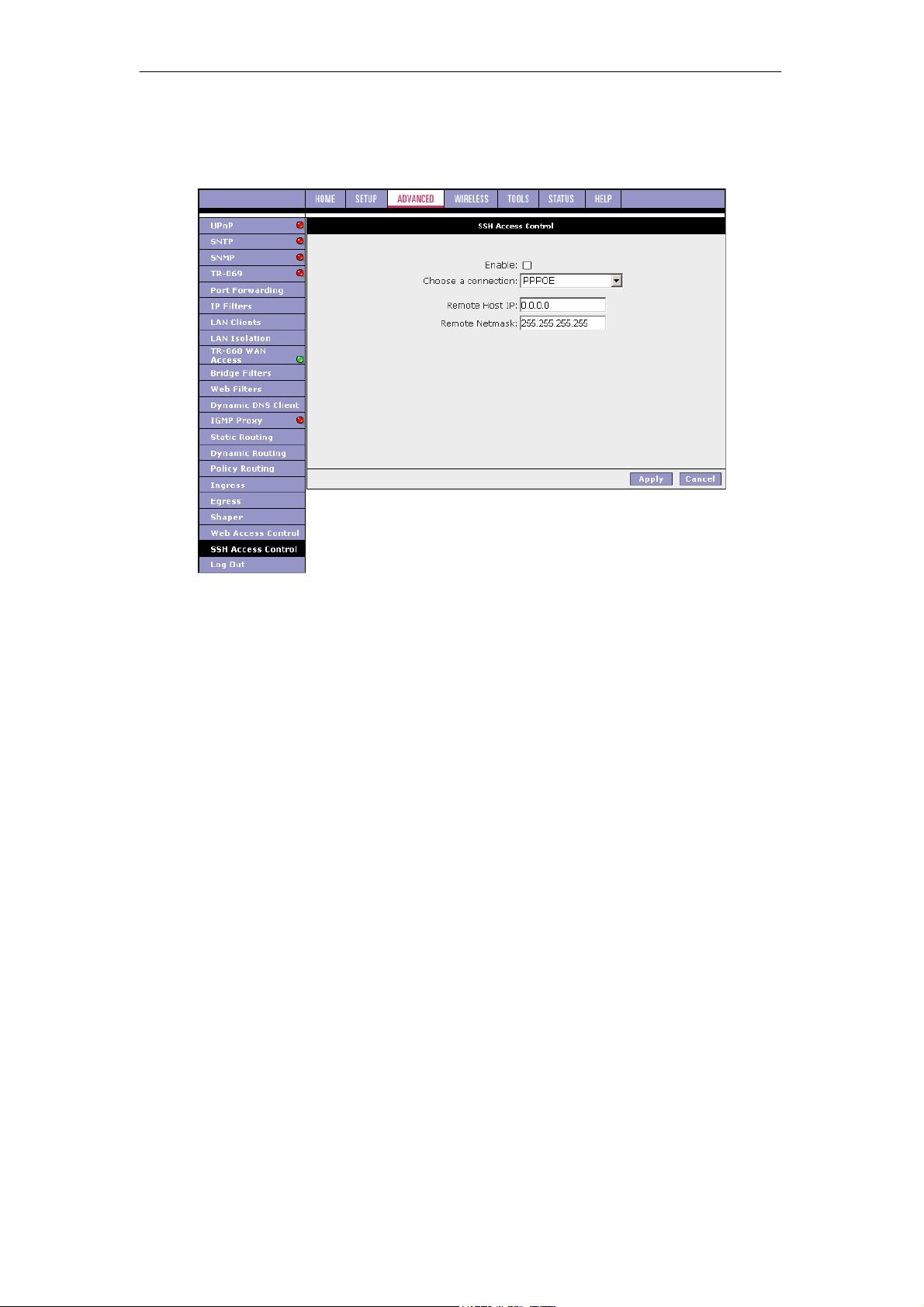
SOHOSpeed ADSL2/2+ Ethernet/Wireless Gateway User’s Manual
3.7.21 SSH Access Control
The SSH Access Control page allows you to access the SOHOSpeed remotely via SSH from
the WAN side.
The configuration of a WAN IP address for SSH access control is very similar to the
configuration of a WAN IP address for Web access control. Refer to ‘‘Web Access Control
Page’’ for field descriptions and configuration procedures.
92
Page 94
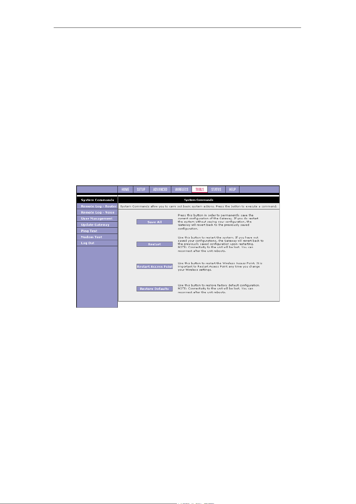
SOHOSpeed ADSL2/2+ Ethernet/Wireless Gateway User’s Manual
3.8 Tools
The SOHOSpeed supports a host of tools which will allow you to customize and debug your
SOHOSpeed.
3.8.1 System Commands
To make the changes permanent you need to click on Tools at the top of the page and select
System Commands. The following commands are used to configure the SOHOSpeed:
z Save all: Press this button in order to permanently save the current configuration of the
SOHOSpeed. If you do re-start the system without saving your configuration, the
SOHOSpeed will revert back to the previously saved configuration.
z Restart: Use this button to re-start the system. If you have not saved your
configurations, the SOHOSpeed will revert back to the previously saved configuration
upon re-starting.
Note: Connectivity to the unit will be lost. You can reconnect after the unit reboots.
z Restart Access Point: Use this button to restart the Wireless Access Point. It is
important to restart Access Point whenever you change your wireless settings.
z Restore Defaults: Use this button to restore factory default configuration.
Note: Connectivity to the unit will be lost. You can reconnect after the unit reboots.
93
Page 95
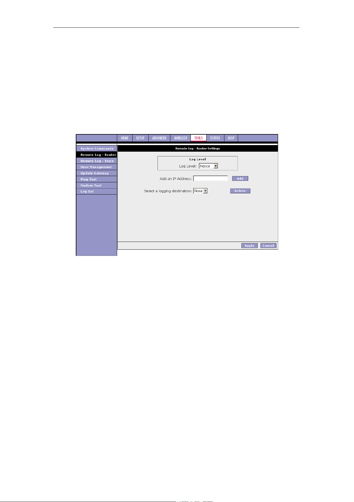
SOHOSpeed ADSL2/2+ Ethernet/Wireless Gateway User’s Manual
3.8.2 Remote Log - Router
The remote log feature is used in conjunction with the PC tool (software provided with your
SOHOSpeed). For PPPoE and PPPoA connections, you can select Debug in the Log Level
field if you want to log the connection information. This is helpful when trying to debug
connection problems. The remote log feature allows you to forward all logged information to
one (or more) remote syslog server. The type of information forwarded to the remote server
depends upon the Log level. Each log message is assigned a severity level, which indicates
how seriously the triggering event affects SOHOSpeed functions. When you configure logging,
you must specify a severity level. Log messages that are rated at that level or higher are sent
to the syslog server and can be viewed using the syslog server application, which can be
downloaded from the web or comes with a linux machine. To view the log information on the
web, refer to ‘‘System Log Page’’.
The remote log configuration procedure is as below:
1. Select you desired Log Level from the drop-down list.
Note: When you select a log level, all log information within this severity level and levels
above (meaning, more severe levels) are sent to the remote station.
2. Enter the IP Address of the remote station (for example, the syslog server) that the log
information is to be sent to, and click Add.
This station is added to the drop-down list of the Select a Logging Destination field.
3. Select the Logging Destination.
You can edit the logging destination list using the Add and Delete buttons.
4. Click Apply.
94
Page 96
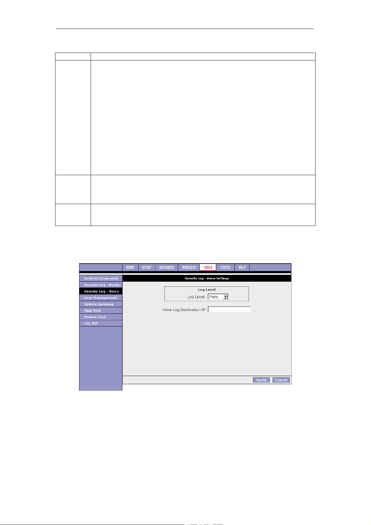
SOHOSpeed ADSL2/2+ Ethernet/Wireless Gateway User’s Manual
Field Description
Field Definition/Description
Log Level
Add an IP
Address
Select a
Logging
Destination
There are eight log levels listed below in order of severity:
z Panic: System panic or other condition that causes the SOHOSpeed to
stop functioning.
z Alert: Conditions that require immediate correction, such as a corrupted
system database.
z Critical: Critical conditions, such as hard drive errors.
z Error: Error conditions that generally have less serious consequences than
errors in the emergency, alert, and critical levels.
z Warning: Conditions that warrant monitoring.
z Notice: Conditions that are not errors but might warrant special handling.
z Info: Events or non-error conditions of interest.
z Debug: Software debugging message. Specify the level only when so
directed by a technical support representative.
The default log level is Notice.
Note: When you select a log level, all log information within this severity level
and levels above (meaning, more severe levels) will be sent to the remote host.
You should enter the IP address of the remote host to which you want the log
information be forwarded. You can add more than more IP address, and any IP
address you add here appears in the drop-down list of the next field: Select a
logging destination.
You can select a destination IP address from the drop-down list. This defines
where the log information will be sent. You can customize the destination list
using the Add and Delete buttons.
3.8.3 Remote Log - Voice
Remote Log - Voice Settings page can be accessed by clicking the Remote Log - Voice link
at the left of the Tools page.
95
Page 97
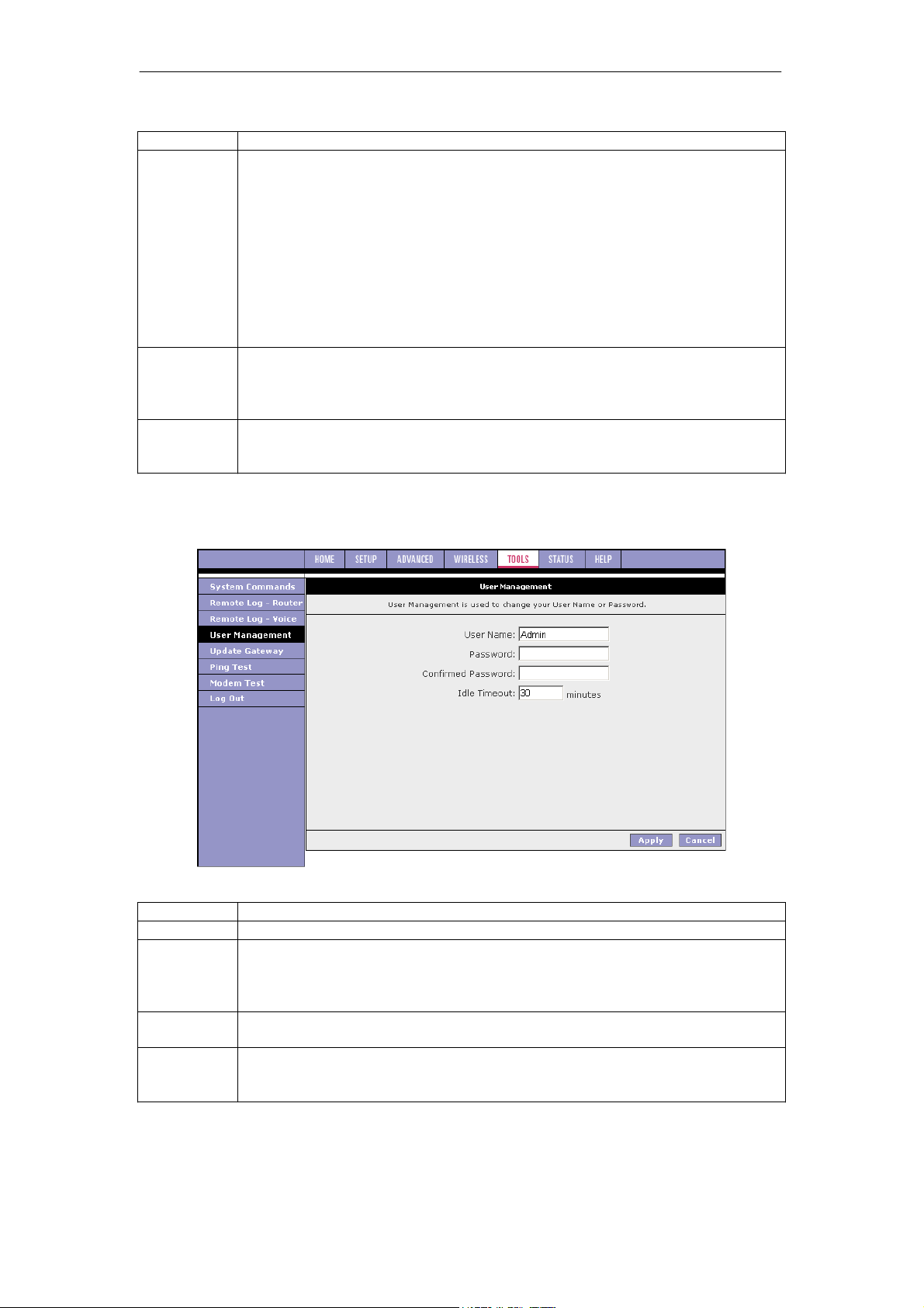
SOHOSpeed ADSL2/2+ Ethernet/Wireless Gateway User’s Manual
Field Description
Field Definition/Description
Log Level
Add an IP
Address
Select a
Logging
Destination
There are eight log levels listed below in order of severity:
z Panic
z Alert:
z Critical
z Error
z Warning
z Notice
z Info
z Debug
The default log level is Panic.
Refer to previous table for more information on each log level.
You should enter the IP address of the remote host to which you want the log
information be forwarded. You can add more than more IP address, and any IP
address you add here appears in the drop-down list of the next field: Select a
logging destination.
You can select a destination IP address from the drop-down list. This defines
where the log information will be sent. You can customize the destination list
using the Add and Delete buttons.
3.8.4 User Management
This page allows you to change your login name and password.
Field Description
Field
User Name
Password
Confirmed
Password
Idle Timeout
Definition/Description
Admin is your default user name. You can enter your new user name here.
Admin is your default password. You can enter your new password here.
Note: If you forget your password, you can press and hold the reset to factory
default button for 10 seconds (or more). The SOHOSpeed will reset to its
factory default configuration and all custom configuration will be lost.
Enter your new password here again to confirm.
The default is 30 minutes. You will need to log back onto the SOHOSpeed after
your session has been inactive for 30 minutes. You can change the timeout
here.
96
Page 98
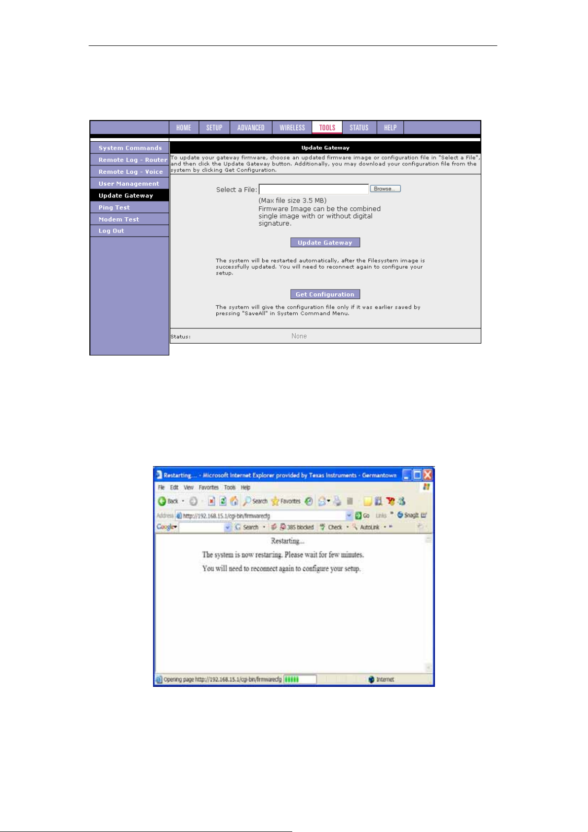
SOHOSpeed ADSL2/2+ Ethernet/Wireless Gateway User’s Manual
3.8.5 Update SOHOSpeed
This page allows you to update the SOHOSpeed’s firmware, voice provision file, and/or
configurations files.
1. Upload firmware: Click Browse and select the firmware image to upload. The file name
should look something like this: nsp.ar7vw.firmware.upgrade.img. The file for web
upload should have “upgrade” in the name. The file without Ϙupgrade” in the name is
for upload using the serial connection.
2. Click Update Gateway.
The status of the uploading appears at the bottom of the page. When the upload is
finished, the SOHOSpeed reboots and you are prompted to log in again.
Note: If you are loading multiple files, it is recommended that you upload the firmware
image at last as the system reboots after loading firmware image.
97
Page 99
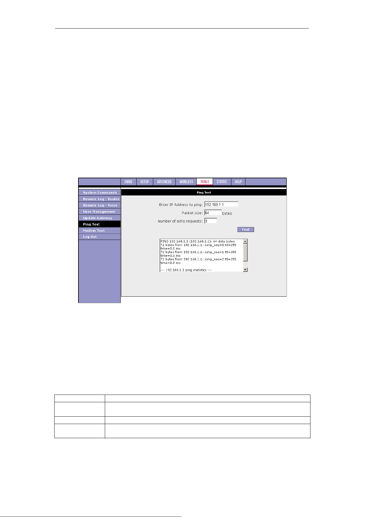
SOHOSpeed ADSL2/2+ Ethernet/Wireless Gateway User’s Manual
3. At the login prompt, enter your Username and Password to log back in.
4. If you want to make sure the firmware is properly upgraded, go to Status/Product
Information and check on the SOHOSpeed version information on the Product
Information page.
5. Upload configuration file: You can use the same procedure to update the configuration
file (config.bin).
6. You can download to your hard drive a copy of the configuration file (config.bin) that has
been saved to the SOHOSpeed flash. To do so, click Get Configuration and follow the
prompt.
7. You can also upload a saved configuration file (config.bin) back to the SOHOSpeed. To
do so, click Browse and select the file, then click Update Gateway.
3.8.6 Ping Test
Once you have your SOHOSpeed configured, it is a good idea to make sure you can ping the
network. If you can ping an IP on the WAN side successfully, you should be able to surf the
Internet.
1. Click Ping Test from the Tools menu to access the Ping Test page.
2. Change or leave the default settings of the following fields:
z Enter the IP Address to Ping
z Packet Size
z Number of Echo Requests
3. Click Test.
The ping results are displayed in the box on the page. If the ping test was successful, it
means that the TCP/IP protocol is up and running. If the Ping test failed, you should
restart the SOHOSpeed.
Field Description
Field
Enter IP
Address to Ping
Packet Size
Number of Echo
Requests
Definition/Description
Enter the WAN-side IP address that you want to ping. The default is set to
the default IP address of your SOHOSpeed (192.168.1.1).
You can define the packet size of the ping test. The default is 64 bytes.
You can define how many times the IP address will be pinged. The default
is 3 times.
98
Page 100
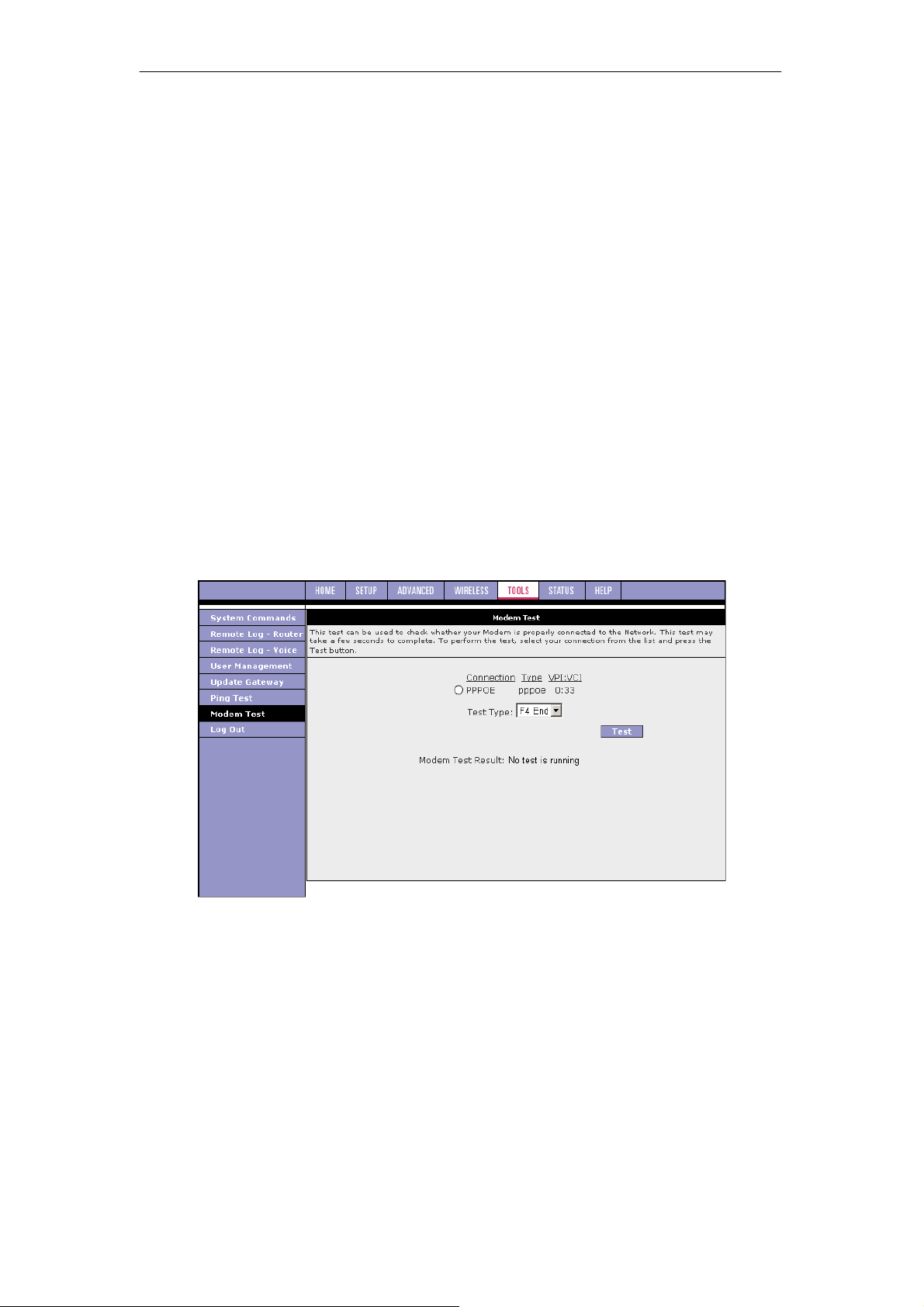
SOHOSpeed ADSL2/2+ Ethernet/Wireless Gateway User’s Manual
3.8.7 Modem Test
The Modem Test page is used to check the connectivity to the WAN. This test ay take a few
seconds to complete. Before running this test, make sure you ave at least one WAN
connection configured and have a valid DSL link. If the SL link is not connected, the test will
fail. Also make sure the DSLAM supports this feature. Not all DSLAMs have F4 and F5
support. F4/F5 cells are used for operation, administration, and maintenance (OAM) on ATM
level. They are used for two main purposes:
z Fault management (detection and notification)
z Loopback testing and link integrity
The ATM OAM is divided into several levels:
z F4: VP level. OAM information flows between network elements (NEs) used within
virtual paths to report an unavailable path or a virtual path (VP) that cannot be
guaranteed. Segment flows are processed, as well as end-to-end flows that terminate in
the management processor.
z F5: VC level. OAM information flows between network elements (NEs) used within
virtual connections to report degraded virtual channel (VC) performance such as late
arriving cells, lost cells, and cell insertion problems. Segment flows are processed, as
well as end-to-end flows that terminate in the management processor.
Both F4 and F5 flows can be configured as one of the test types:
z Segment: This test verifies that ATM continuity exists between the virtual channel link
segment from the SOHOSpeed to the DSL provider network (typically this is a DSLAM
at the DSL provider site).
z End-to-End: This test verifies ATM connectivity of the virtual channel link with the ATM
endpoint, such as a remote broadband access router located at the DSL provider or ISP
site.
99
 Loading...