

Castle group Sonus Range GA116L, Sonus Range GA216L, Sonus Range GA257L, Sonus Range GA116E Operating Manual


www.castlegroup.co.uk
Castle Sonus Range
Sound Level Meter
&
Dose Meter
Operating Manual

Castle Sonus Range
Sound Level & Dose Meter Operating Manual
Published by Castle Group Ltd
Castle Group Ltd
Salter Road
Scarborough
North Yorkshire
YO11 3UZ, UK
Copyright © Castle Group Ltd 2012
All rights reserved. No part of this publication may be reproduced, stored in a
retrieval system or transmitted, in any form or by any means, electronic,
mechanical, photocopying, recording or otherwise, without the prior permission
of the copyright holder.
Printed in the UK
HB/0116/005/A5 Rev B

Thank you for buying a Castle product, I am sure you will find both the goods and
the service to be of the highest quality but if not, then please feel free to write to
me personally and I will ensure that your needs are dealt with immediately.
This manual is designed to show you the operation of the goods you have
purchased and a very brief insight into acoustics itself. If you would like to
become a competent person in the eyes of the law, then you may like to know
more about our Competent Persons training course for the Noise at Work
Regulations. You can visit www.castletrainingacademy.com to find out more.
Castle Group has become the leading supplier of solutions for health and safety,
environmental compliance and plant maintenance and monitoring, with an ever
expanding offer comprising equipment for sale or rent, residential or in-house
training courses, consultancy services and equipment calibration. If you would
like to know more about any of our other products and services then please visit
www.castlegroup.co.uk or telephone us on +44(0)1723 584250.
Simon Bull
Managing Director
Note: for ‘Getting Started’ section please turn to Chapter 4

Precautions
• Only operate the instrument as described in this manual.
• These are precision instruments, protect from shocks and vibrations.
• Ambient conditions for the operation of the unit are as follows:-
Temperature: -10°C to +50°C
Relative Humidity: 25 to 90%
• Protect the unit from extremes of temperature and humidity, direct
sunlight and air with a high salt or sulphur content.
• Always turn the unit off after use. Remove the batteries from the
instrument when not in use.
• Do not use any solvents or cleaning agents on the instrument. Use only a
soft dry cloth or a soft cloth lightly moistened with water when necessary.
• Do not allow any conductive objects, such as wire or metal particles to
enter the unit.
• Do not try to disassemble the instrument or attempt any repairs as this will
invalidate your warranty. Take a note of the condition of the instrument and
contact your authorised Castle service station.
• To ensure continued precision performance of your instrument have it
checked and serviced at regular intervals.
Contacting Castle Group
This manual contains complete operating instructions for the Castle Sonus
Meter, read it carefully and you will quickly become familiar with your instrument
and its operation.
If you do encounter problems with the operation of your instrument please feel
free to contact customer support with your enquiry on: -
Telephone: +44 (0)1723 584250
Fax: +44 (0)1723 583728
Website:
www.castlegroup.co.uk
Email: techsupport@castlegroup.co.uk
sales@castlegroup.co.uk

Contents
CHAPTER 1 .......................................................................................... 1
Introduction ........................................................................................................................................ 1
Sonus Variations ........................................................................................................................ 2
Sonus L...................................................................................................................................... 2
Sonus E ..................................................................................................................................... 3
Sonus I ....................................................................................................................................... 3
Sonus B ..................................................................................................................................... 3
CHAPTER 2 .......................................................................................... 4
Microphone ........................................................................................................................................ 4
Microphone Types ..................................................................................................................... 4
Free Field .................................................................................................................................. 4
Pressure ................................................................................................................................... 4
Random Incidence ............................................................................................................... 4
Microphone Polarisation ........................................................................................................ 4
Externally Polarised ............................................................................................................. 4
Pre-Polarised .......................................................................................................................... 4
Microphone Sensitivity ............................................................................................................ 5
Certifiable Calibration .............................................................................................................. 5
Removal of Microphone .......................................................................................................... 5
Pre-Amplifier Removal and Fitting ........................................................................................... 6
Models GA116L, GA116E, GA116I & GA216L-P .................................................... 6
Microphone Extension Cable (Models GA116L, GA116E & GA216L) ..... 6
CHAPTER 3 .......................................................................................... 7
Measuring Sound ............................................................................................................................ 7
Sound Level – General Advice ............................................................................................. 7
Reflections ..................................................................................................................................... 8
Time Weighting ........................................................................................................................... 8
Slow Weighting ..................................................................................................................... 8
Fast Weighting ...................................................................................................................... 8
Impulse Weighting – (Models GA116E, GA116L & GA216L Only) ........... 8
Frequency Weighting Filters ................................................................................................ 9
‘A’ Weighting .......................................................................................................................... 9
‘C’ Weighting .......................................................................................................................... 9
‘Z’ Weighting (Zero) – (Models ‘E’ & ‘L’ Only) ......................................................... 9
Overload and Under Range Conditions ........................................................................ 10
Overload Condition ............................................................................................................ 10
Under Range Condition .................................................................................................. 11
Measuring Ranges ................................................................................................................. 12
Changing Range – All models except GA257B and GA257L .................... 12
Lock Keypad – GA257B and GA257L ................................................................... 13
CHAPTER 4 ....................................................................................... 14
Getting Started .............................................................................................................................. 14
Models I and B .......................................................................................................................... 14
Models L and E ......................................................................................................................... 14
All Models ................................................................................................................................... 15
Keypad Layout – GA116, GA216 All Models ........................................................... 16

Keypad Layout – GA257L & GA257B ......................................................................... 17
Powering Your Sonus Meter ............................................................................................. 18
Switching Your Sonus Meter On/Off ............................................................................ 19
CHAPTER 5 ....................................................................................... 20
Main Menu Navigation ............................................................................................................... 20
Models GA116I, GA216I, GA116B, GA216B, GA257B .............................. 21
Calibration [CAL <OK] ................................................................................................ 21
Exposure Time [ET <OK] ........................................................................................... 23
Frequency / Time Weighting [WTG <OK] ....................................................... 23
Exchange Rate [EXCH <OK] .................................................................................... 24
Criterion [CRIT <OK] ................................................................................................... 25
Threshold [THR <OK] ................................................................................................. 26
Keypad Lock [LOCK <OK] ......................................................................................... 26
Display Contrast [CONT <OK] ................................................................................ 27
Models GA116L, GA216L, GA116E, GA257L .................................................. 28
Calibration [CAL] .......................................................................................................... 28
Instrument Settings [SETUP] ................................................................................ 30
Frequency Weighting [FREQ WGT] .............................................................. 31
Time Weighting [TIME WGT] ........................................................................... 32
Recording Interval Period [INTERVAL] ........................................................ 34
Display Contrast [CONTRAST] ........................................................................ 36
Percentiles [USER Ln] ......................................................................................... 37
Criterion Level [CRIT] ........................................................................................... 38
Threshold [THR] ..................................................................................................... 39
Exchange Rate [EXCH] ........................................................................................ 40
Record Timer [TIMER] ........................................................................................ 41
Current Date [DATE] ............................................................................................ 42
Real Time Clock [TIME] ....................................................................................... 43
User Mode [MODE] .................................................................................................... 44
View Saved Logs [LOGS] .......................................................................................... 45
Delete Saved Logs [DELETE] .................................................................................. 46
Set Instrument Defaults [DEFAULTS] ............................................................... 47
Keypad Lock [LOCK] ................................................................................................... 48
CHAPTER 6 ....................................................................................... 49
Stop / Record Mode .................................................................................................................. 49
Model ‘I’ & ‘B’ Instruments ................................................................................................. 49
Model ‘L’ & ‘E’ Instruments ................................................................................................ 50
All Models ................................................................................................................................... 51
Model ‘I’ & ‘B’ Instruments – Information Screen ............................................ 51
Model ‘L’ Instruments – Information Screen ...................................................... 52
Model ‘E’ Instruments – Information Screen ...................................................... 53
Reset Data ........................................................................................................................... 54
Models ‘I’ & ‘B’ .............................................................................................................. 54
Models ‘L’ & ‘E’ .............................................................................................................. 54
CHAPTER 7 ....................................................................................... 55
Parameters ..................................................................................................................................... 55
Available Parameters - Models ‘I’ & ‘B’ ........................................................................ 55
Available Parameters - Model ‘L’ ..................................................................................... 57
Available Parameters - Model ‘E’ ..................................................................................... 59
Parameter Explanations ...................................................................................................... 61
Sound Pressure Level ..................................................................................................... 61

Equivalent Continuous Sound Level .......................................................................... 61
Maximum Sound Pressure Level .............................................................................. 62
Peak Level ............................................................................................................................. 62
Daily Personal Noise Exposure Level ....................................................................... 63
Noise Dose ........................................................................................................................... 64
Noise Dose per Hour ...................................................................................................... 65
Pascal Squared Hours ................................................................................................... 65
Sound Exposure Level ..................................................................................................... 66
Percentiles ........................................................................................................................... 66
CHAPTER 8 ....................................................................................... 67
Downloading Saved Recordings ............................................................................................ 67
Models ‘L’ and ‘E’ ..................................................................................................................... 67
CHAPTER 9 ....................................................................................... 68
Accessories ..................................................................................................................................... 68
Available Accessories ........................................................................................................... 68
CHAPTER 10 .................................................................................... 69
Technical Specification ............................................................................................................... 69
Instrument Standards .......................................................................................................... 69
Measurement Parameters ............................................................................................... 70
Time Weighting ........................................................................................................................ 71
Frequency Weighting ............................................................................................................ 71
Peak Frequency Weighting ................................................................................................ 72
Typical Electrical Self Generated Noise Level ........................................................... 72
Linear Operating Range: (IEC 61672:2002) ............................................................ 73
Model ‘L’ Instruments ..................................................................................................... 73
Model ‘E’ Instruments ..................................................................................................... 75
Model ‘I’ & ‘B’ Instruments ........................................................................................... 76
Total Measuring Range ....................................................................................................... 77
GA116E ................................................................................................................................. 77
GA116L ................................................................................................................................. 77
GA216L ................................................................................................................................. 77
GA257L ................................................................................................................................. 77
GA116I, GA216I, GA116B, GA216B ..................................................................... 77
GA257B................................................................................................................................. 77
Peak Operating Range @ 1kHz ......................................................................................... 78
GA116E ................................................................................................................................. 78
GA116L ................................................................................................................................. 78
GA216L ................................................................................................................................. 78
GA257L ................................................................................................................................. 78
GA116I, GA216I, GA116B, GA216B ..................................................................... 78
GA257B................................................................................................................................. 78
Acoustic Frequency Range ................................................................................................ 79
Electrical Characteristics .................................................................................................... 79
Reference Points .................................................................................................................... 79
Model E .................................................................................................................................. 79
Model L................................................................................................................................... 79
Models I, B ............................................................................................................................ 79
Electrical Signal Input ............................................................................................................ 80
Maximum Peak to Peak Electrical Signal Input For No Damage..................... 80
Upper Frequency for Periodic Acoustic Testing ...................................................... 80
Windshield .................................................................................................................................. 80

Microphone [GA116I, GA116L] ...................................................................................... 81
Microphone [GA116E] ......................................................................................................... 82
Microphone [GA216I, GA216B, GA216L, GA257B, GA257L] ...................... 83
Typical Microphone Self Generated Noise Level ..................................................... 84
Maximum SPL at the Microphone for No Damage ............................................... 84
Calibration Reference Conditions ................................................................................... 84
Display .......................................................................................................................................... 85
Display Refresh Rate ............................................................................................................. 85
Detector Characteristics .................................................................................................... 85
Warm up time .......................................................................................................................... 85
Environmental Stabilization Time .................................................................................... 85
Operating range ...................................................................................................................... 85
Effect of Temperature .......................................................................................................... 85
Effects of Humidity .................................................................................................................. 85
Effects of Vibration ................................................................................................................. 86
Magnetic Field .......................................................................................................................... 86
Radio Frequency Fields ........................................................................................................ 86
Overload ....................................................................................................................................... 86
Log Interval Periods: Models ‘L’ & ‘E’ Only .................................................................. 86
Timer Function: Models ‘L’ & ‘E’ Only ............................................................................. 86
Time & Date: Models ‘L’ & ‘E’ Only .................................................................................. 86
Overall Dimensions................................................................................................................. 86
Batteries ..................................................................................................................................... 87
Overall Weight including Batteries ................................................................................. 87
Manufacturers Data ............................................................................................................. 87
Case Reflections ...................................................................................................................... 87
Output Socket ........................................................................................................................... 88
GA116I ................................................................................................................................... 88
Wiring Configuration ................................................................................................. 88
AC Output ........................................................................................................................ 88
DC Output ........................................................................................................................ 88
GA116L, GA116E, GA216L, GA257L ................................................................... 89
Wiring Configuration ................................................................................................. 89
AC Output ........................................................................................................................ 89
EC Declaration of Conformity ............................................................................................ 90
CHAPTER 11 .................................................................................... 91
Function Equations ....................................................................................................................... 91
CHAPTER 12 .................................................................................... 96
Glossary ............................................................................................................................................. 96
A-weighting ................................................................................................................................. 96
Action Values ............................................................................................................................ 96
Ambient Noise .......................................................................................................................... 97
Audio Frequency Range ....................................................................................................... 97
Audiometer ................................................................................................................................ 97
Background Noise .................................................................................................................. 97
C-weighting ................................................................................................................................. 97
Criterion Duration (TC) ......................................................................................................... 98
Criterion Sound Level (LC) .................................................................................................. 98
Daily Personal Noise Exposure Level (Lep,d) ............................................................. 98
Decibel (dB) ................................................................................................................................ 99
Digital Signal Processor (DSP) ...................................................................................... 101
Doppler Effect ........................................................................................................................ 101

Dose ........................................................................................................................................... 101
Dynamic Range ..................................................................................................................... 101
Equivalent Continuous Sound Level (Leq) ................................................................. 102
Exchange Rate ....................................................................................................................... 102
Fast Fourier Transform (FFT) ........................................................................................ 104
Feedback .................................................................................................................................. 104
Frequency (Hz) ...................................................................................................................... 104
Frequency Weighted Filter .............................................................................................. 105
Frequency Band Filter ........................................................................................................ 108
Hearing Protection .............................................................................................................. 108
Leq ............................................................................................................................................... 111
Minimum rms Level (Lmin) ............................................................................................. 111
Maximum rms Level (Lmax) ........................................................................................... 112
Microphone ............................................................................................................................. 112
Noise .......................................................................................................................................... 112
Noise Dose .............................................................................................................................. 113
Noise Floor .............................................................................................................................. 114
Overload .................................................................................................................................... 114
Pre-Amplifier ........................................................................................................................... 114
Percentile Sound Levels ................................................................................................... 115
Peak Level ................................................................................................................................ 116
Pink Noise ................................................................................................................................ 116
Residual Noise ....................................................................................................................... 117
Root Mean Square (rms) ................................................................................................. 117
Sound ......................................................................................................................................... 117
Sound Exposure (SE) .......................................................................................................... 117
Sound Exposure Level (LAE)............................................................................................ 118
Sound Power (W)................................................................................................................. 118
Sound Power Level (LW) .................................................................................................. 118
Sound Pressure .................................................................................................................... 118
Sound Pressure Level (Lp) .............................................................................................. 119
Specific Noise ........................................................................................................................ 119
Speed of Sound (c) .............................................................................................................. 119
Threshold Sound Level (Lt) .............................................................................................. 119
Time Weighting ..................................................................................................................... 120
Under Range .......................................................................................................................... 120
White Noise ............................................................................................................................ 120
Z-weighting .............................................................................................................................. 120
CHAPTER 13 ................................................................................. 121
Customer Instrument Support ........................................................................................... 121
Warranty and After Sales Service .............................................................................. 121
Trouble Shooting Guide ..................................................................................................... 122
Instrument Disposal ........................................................................................................... 123
Disclaimer................................................................................................................................ 124
Instrument Details ............................................................................................................... 124

Table of Figures
Figure 1 – Frequency Weighting Curves .................................................................................. 9
Figure 2 – Keypad Layout (Sound Meter) .............................................................................. 16
Figure 3 – Keypad Layout (Dose Meter) ................................................................................ 17
Castle Group Ltd
If you want to keep up to date with the latest in health and safety, you
should attend a Castle FREE seminar. These are run around the country
and cover a wide range of topics. Packed with the latest information and
delivered with the help of practical demonstrations, these seminars are
a great way to really learn something at the same time as collecting cpd
points! Go to the website below to find the lasts dates and venues and to
see video clip samples.
www.need2know4free.com
Dedicated to professionals
in Health and Safety,
Environmental Compliance
and Plant Maintenance
Engineering, Castle set out
to help you in a way that
suits you best. We can
provide or rent equipment,
train you and your staff or
we can carry out work on
your behalf. We can even
mix it up to suit your way of
working.
• Measuring and Monitoring Instruments
• Equipment Rental
• Database and Data-management Software
• Training Courses and In-house Provision
• Calibration and Repair of Monitoring Equipment
• Consultancy for Health, Safety, Environment and Engineering
Solutions
• Online Knowledge
www.castlegroup.co.uk
HEALTH AND SAFETY
Compliance with legislation and mitigation of claims is really what health
and safety is about for most companies. That is how we are set up to
help you; Our training courses are all geared to that end as is any
equipment we might supply or rent to you. If you need us in person, we’ll
be there too! Call NOW on 01723 584250 and get your health and
safety compliance on-track, the way you want to do it! There are many
issues you might like us to have a look at
• Noise and Vibration at Work
• Audiometry
• HAVS Health Surveillance
• Health Screening
• Air Sampling and Gas Detection
• Indoor Air Quality
• Airflow
• EMF Testing and Monitoring
• Portable Appliance Testing (PAT)
• General Compliance and Risk
Assessment
ENVIRONMENTAL COMPLIANCE
In an increasingly sensitive atmosphere to environmental issues,
businesses have to be careful. Neighbours are increasingly aware of
theirs ‘right’ to complain and the environmental agencies are looking for
industry to clean up its act. Simply call us on 01723 584250 if you
have any environmental compliance issues and we will work with you to
find the best way forward.
• Noise for Planning
• Complaint Management
• Ground-Bourne & Building Vibration
• Stack-Emissions Monitoring
• Environmental Air Sampling
• Water Quality Testing
MAINTENANCE AND DIAGNOSTICS
Production plant needs maintenance and if this can be done only when
needed, then cost savings can be huge. Condition monitoring offers the
ability carry out predictive maintenance so shut-down is only when you
plan it and only when it’s needed. It is very simple to work out if this is the
right approach for your business, so give us a call on 01723 584250
so we find out how much you could save!
• Vibration Monitoring Systems
• Vibration Meters
• Temperature Monitoring System
• Thermometers
• Thermal Imaging
• Diagnostic Vibration Analysis
• Tachometers
• Inspection Endoscopes
Services
Castle Training Academy
Competence and Compliance training is essentially all about obtaining
the knowledge and skills required to get the job done. This is precisely
how Castle courses are set out, with a high degree of practical ‘handson’ experience mixed with some background theory and a lot of jobspecific information and discussion. If this doesn’t whet the appetite,
then there is also a fully inclusive dinner on the first nigh – perfect for
getting to know some of your peers! You can see a full list of courses on
our website.
• Health and Safety Compliance Courses
Noise, Vibration, COSHH, Asbestos
• Health Surveillance Courses
Audiometry, Lung Function, HAVS
• Environmental Monitoring Courses
Noise, Vibration, Air Quality
• Diagnostic Engineering Courses
• Maintenance and Monitoring Courses

In-house and Bespoke Training
The benefits of in-house training can be extensive. Training can be
tailored to your company, the timing can be made to suit your needs, you
get to keep your staff on-site and you can train many people at one go!
You can pick any of our standard courses, a shortened version as an
awareness session or a toolbox talk, or you can design your own course
covering a large range of topics. Visit our website for a list of ideas!
Castle Consultancy
Sometimes, the comfort of using an independent expert can be
extremely valuable, whether that be for short-term help, Engineering
project work, or an on-going support contract. Castle consultants are
always at the top of their game and are waiting to hear from you. Have a
look at our website or call on 01723 584250.
• Noise and Vibration, COSHH
Assessments
• Light, Temperature, EMF
Assessments
• Environmental Monitoring
• Expert Witness
• Diagnostic Engineering
• Engineering Control Solutions
• Risk Management
• Health Surveillance Services
• Health and Safety ‘Department’
Support Service
Castle Care
Maintaining calibrations on measuring equipment is absolutely essential
to the integrity of your data. At Castle, we can calibrate virtually anything
you have that can measure. We pride ourselves in fast-as-possible
turnaround times and can normally give up-front prices for almost any
equipment. Whether you have an anemometer, or a ‘zero-g‘
accelerometer, then call us for a price on 01723 584250.
• If it Measures, and can be done - we’ll Calibrate it
• UKAS Certificates Available
• Multiple levels of Calibration
Equipment Types Covered
• Air quality meters
• Air sampling pumps
• Air sampling calibrators
• Anemometers
• Audiometers
• Balances/Scales
• Barometers
• Dosemeters
• Electrical test equipment
• Force meters
• Gas Detectors
• Hygrometers
• Light meters
• Manometers
• Moisture meters
• Noise meters
• Pressure meters
• Sound level meters
• Sound Analysers
• Strain gauges
• Tachometers
• Thermometers
• Thermo-hygrometers
• Thickness meters
• Timers
• Vibration meters
• Vibration analysers
• Weighing equipment
Castle Contract
If peace of mind for equipment calibrations is important to you – and it
should be, then check out our contract calibration deals. We will give you
discounted, fixed-annual-pricing for selections of equipment and we will
undertake to ensure calibration is maintained to your schedule. This is
designed to take all the hassle out of equipment calibration.
• Maintain Instrument Calibrations
• Hassle-Free Administration
• Discounted Calibration Fees
• Single-Source Supplier
Castle Rent
Rental is a great way to have the use of measurement equipment
without having to own it – especially is capital budgets are tight or it tax
is an issue. If you need a short term solution, additional equipment to
boost your capabilities or if contract-based tax deduction is important,
then Rental could well be the way to go. Go to our website to find the
huge range of equipment we have available.
You might also like to make use of our ex-rental purchase as a way of
keeping your equipment costs down.
• Easy on Cash-Flow
• Short or Long Term
Rentals
• Let the Taxman Pay on
Contracts
• Try Before You Buy
• 4 weeks for the Price of 3!
• No On-going Maintenance
If it exists - we’ll even source equipment for you!
www.castlegroup.co.uk
01723 584250

Page 1
Chapter 1
Introduction
Thank you for purchasing your product from Castle Group Ltd. The Sonus range
of pocket sound level meters brings simplicity and power to the worlds of Noise
at Work and Environmental sound monitoring.
From a basic sound pressure meter to full data logging, combined sound and
dose-meter, the range of systems covers a wide diversity of applications.
Portability of instrumentation is essential for effective noise measurement. As
the name indicates, the Castle Sonus Pocket Meter packs all the necessary
features into pocket sized proportions.
Future Proof…
The built in firmware for these meters is designed to suit future upgrading for
feature enhancements, legislative changes or instrument upgrades. Details are
mailed to customers as soon as they become available. With the Castle range
of Sonus Pocket meters you will always be in step with the law and market
requirements. Periodic enhancements or bug fixes to the software will be
supplied free of charge for a period of one year from the purchase date.

Page 2
Sonus Variations
Sonus L
GA116L – Class 1, Ln’s, User Selectable Modes
GA216L – Class 2, Ln’s, User Selectable Modes
Available in either class 1 or class 2, this top of the range model is a Noise at
Work and Environmental Sound Meter boasting a combined Integrating Sound
Level Meter and Dose Meter with full data logging capability.
Simply unplug the Sound Meter Microphone and plug in the Dose Meter cable to
convert to a fully functional Dose Meter (Model GA116L Only).
This model also features dual measurement capability meaning two versions of
applicable parameters can be measured simultaneously. This feature means
you only ever need to measure once to capture all the data you need!
The instrument has user selectable operating modes for instant automatic
setup of the instrument for Noise at Work or Environmental parameters.
Alternatively the instrument can be configured manually to meet your exact
requirements.
Analysis of recorded data can be achieved by transferring the data from the
instrument into the software dBdataPro using the instruments USB port.
GA257L –Dose Meter
This model is a dedicated Dose Meter with full data logging capabilities which
also features dual measurement capability meaning two versions of applicable
parameters can be measured simultaneously. This feature means you only ever
need to measure once to capture all the data you need!
Analysis of recorded data can be achieved by transferring the data from the
instrument into the software dBdataPro using the instruments USB port.

Page 3
Sonus E
GA116E – Class 1, Ln’s,
Available in class 1 only, this top of the range model boasts an ultra low noise
floor allowing extremely quiet noise to be measured and recorded.
This model also features dual measurement capability meaning two versions of
applicable parameters can be measured simultaneously. This feature means
you only ever need to measure once to capture all the data you need!
This model is ideal as a dedicated Environmental Sound Meter with full data
logging capabilities recording samples with an interval period as low as one
second … even Ln’s.
Analysis of recorded data can be achieved by transferring the data from the
instrument into the software dBdataPro using the instruments USB port.
Sonus I
GA116I – Class 1
GA216I – Class 2
Available in either class 1 or class 2, this model is a low cost integrating sound
level meter that measures simultaneous Leq and peak measurement for
assessments and compliance with the Health and Safety at work Act; Noise at
Work Regulations 1989.
Sonus B
GA116B – Class 1
GA216B – Class 2
Available in either class 1 or class 2, this model is a general purpose low cost
non-integrating sound level meter that can assist with compliance to the Health
and Safety at Work Act; Noise at Work Regulations 1989.
GA257B –Dose Meter
A low cost dedicated Dose Meter giving a simultaneous Daily Noise Exposure
Level (Lep,d) and peak measurement (Zpk) for assessments to the Noise at
Work Regulations 1989.

Page 4
Chapter 2
Microphone
Measurement microphones by the very nature of their manufacture are
precision components that are easily damaged through incorrect use. Great
care must be taken when using the instrument to ensure the longevity of the
microphone.
Please note that depending on your instrument model, it may be supplied
with a protective white plastic cap covering the end of the microphone. If
supplied this cap must be removed prior to using the instrument.
Microphone Types
Three different types of microphone are manufactured, each designed for
measuring noise in different applications which is out of the scope of this
manual. Each one however has a different sound incidence angle. The sound
incidence angle determines the angle the instrument is held relative to the
actual noise source being measured.
Free Field
Sound Incidence Angle = 0°
Point the sound meter directly towards the noise source
Pressure
Sound Incidence Angle = 90°
Point the sound meter at 90° to the noise source
Random Incidence
Point the sound meter at approximately 70° to the noise source
All Sonus meters are supplied with Free Field measurement microphones.
Microphone Polarisation
Microphones require a polarisation voltage to operate and are manufactured in
two ways. All microphones supplied with Sonus meters are Pre-Polarised.
Externally Polarised
These microphones require an external charge for the microphone to operate
which is generally 200V and supplied by the sound level meter.
Pre-Polarised
These microphones generate the polarisation voltage internally and do not
require the externally generated 200V polarisation charge.

Page 5
Microphone Sensitivity
The sensitivity of a microphone is determined by the output voltage it produces
for a defined sound source.
Microphones are manufactured with numerous sensitivity levels and operate
within a specified tolerance. Different microphones of the same model may
therefore give slight differences in readings when used on the same sound
meter. To allow for this all Sonus meters have been designed to accommodate
any variations in the tolerance of the supplied microphone up to ±3dB.
Sonus models L, I and B have been designed for microphones with a sensitivity
of 25mV/Pa and model E for microphones with a sensitivity of 50mV/Pa.
Great care must be taken to ensure the microphone and sound meter
sensitivities match otherwise incorrect readings will occur.
Certifiable Calibration
The calibration process includes the microphone, pre-amplifier and sound level
meter. Any change in this measurement chain will require a new certifiable
calibration.
Castle Group Ltd offers a complete calibration service offering either a full UKAS
calibration or a standard NPL traceable calibration which can be supplied with
or without a test report.
It is recommended that your sound meter instrumentation is calibrated annually
to ensure your measuring equipment is completely accurate and fully compliant.
Removal of Microphone
The microphone can be fitted to the pre-amplifier by screwing the microphone in
a clockwise direction ensuring that the pre-amplifier spring pin is located
centrally in the microphone. To remove the microphone unscrew in an anticlockwise direction.
The microphone has a protection grid which can also be unscrewed and
removed, great care must be taken to ensure that this is NOT removed.
Underneath the protection grid is the microphone diaphragm which should
never be touched or be subject to dust or dirt. Doing so may damage the
microphone beyond repair or affect its acoustic response.

Page 6
Pre-Amplifier Removal and Fitting
Models GA116L, GA116E, GA116I & GA216L-P
To attach the pre-amplifier, position the orientation key on the pre-amplifier
which is identified with a RED mark, with the RED identification mark on the
instrument and gently push the pre-amplifier into the connector. To remove,
gently pull the pre-amplifier stem away from the instrument body. DO NOT
TWIST THE MICROPHONE STEM.
Microphone Extension Cable (Models GA116L, GA116E & GA216L)
To attach the microphone extension cable, position the orientation key on the
extension cable connector which is identified with a RED mark, with the RED
identification mark on the instrument and gently push the extension cable into
the connector on the instrument. To fit the pre-amplifier to the extension cable
see Attaching & Removing the Pre-Amplifier above.
To remove, gently pull the extension cable connector by pulling on the knurled
part of the stem. DO NOT TWIST THE MICROPHONE STEM.

Page 7
Chapter 3
Measuring Sound
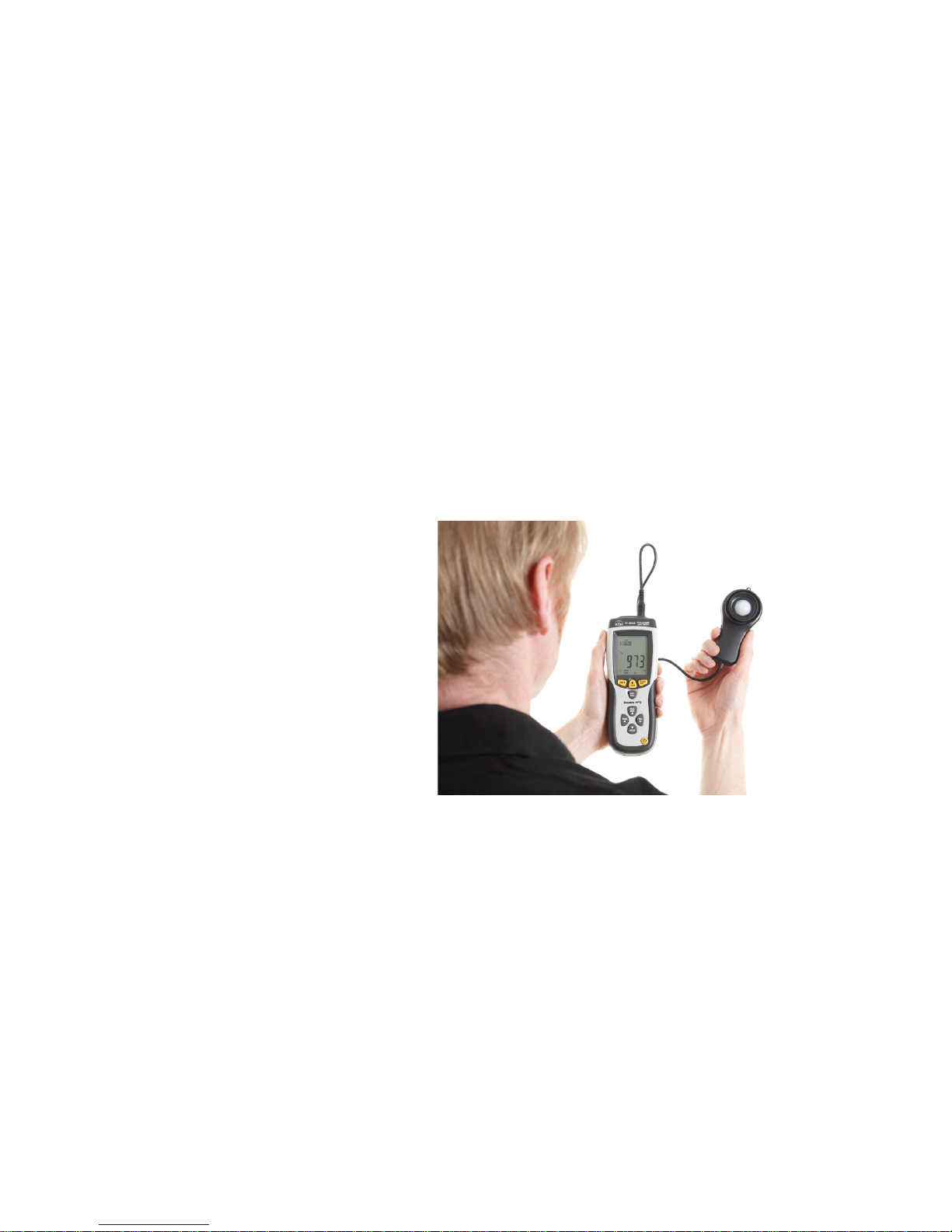
Always calibrate your instrument prior to, and after taking measurements using
a known sound source such as the Castle GA607 sound level calibrator. The
type of microphone supplied with your instrument is Free Field and requires an
incidence angle of 0°, therefore whilst measuring always point your Sonus
Pocket Meter directly towards the noise source being measured.
Sound Level – General Advice
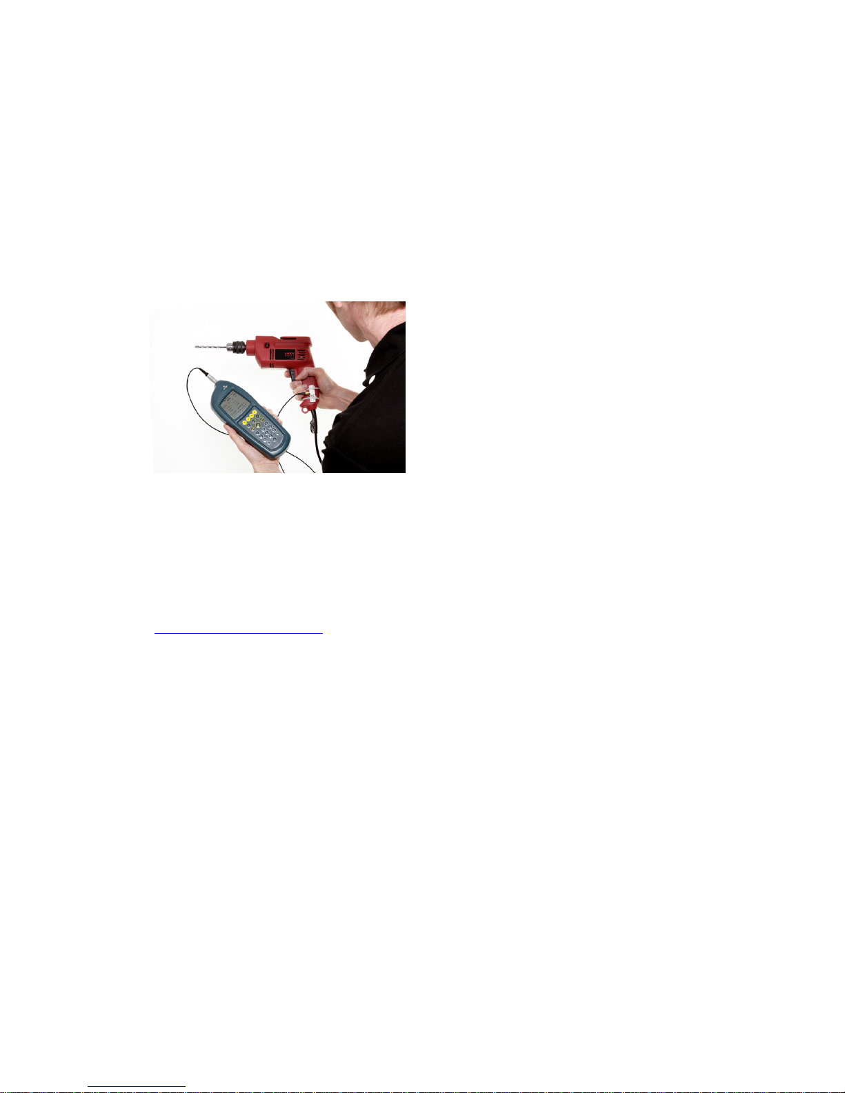
In some environments, high levels of noise can occur. The Castle Sonus Pocket
sound meter has therefore been designed for complete accuracy up to sound
levels of 140dB.
Before you record measurements take the time to ensure you have chosen the
optimum range for the process to be recorded. Wherever possible, the
optimum range is when the average measured signal is approximately half way
between the top of the range and the bottom of the range without an overload
condition.
Where high levels of noise are encountered the meter may register an overload
and in these circumstances the meter will display that this has occurred, it is
therefore advisable to determine if an Over Load occurs on the selected range.
In such cases you will need to select a higher range to accommodate the higher
peak levels. See Technical Specifications for peak range limits on each
individual range.
If the noise levels are too low for the range selected then the meter will display
an under range condition. Under these circumstances you will need to select a
lower range.
For more detailed information see Overload and Under Range Conditions and
Measuring Ranges.
If measuring low level noise then be aware of the inherent noise levels caused by
a combination of thermal and electrical noise from both the microphone and the
sound level meter. Measuring data that lies within 10dB of the lowest quoted
level on the lowest measuring range may be influenced by the self noise of the
system. See Technical Specifications for inherent noise levels and range limits.

Page 8
Reflections
The sound level meter operator and the sound level meter itself can interfere
with the measurements being made, reflecting the noise signal. The instrument
case for the Sonus range of sound level meters has therefore been designed to
minimize reflections whilst also being of rugged construction.
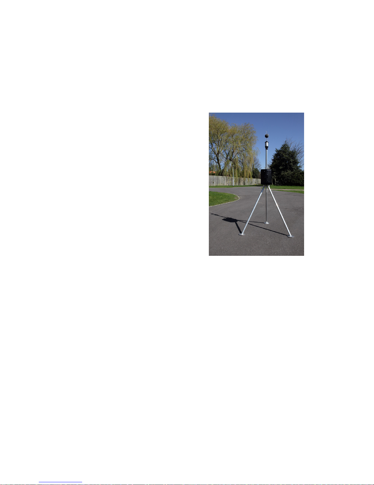
To minimize reflections from the operator hold the sound level meter at arm’s
length, mount the sound meter on a suitable tripod (adapter required) or use a
microphone extension cable (if applicable).
Time Weighting
The time weighting is a time constant that modifies the response of the
instrument to fluctuating noise levels. Without time weighting the meter display
would fluctuate following the measured noise level and would be unreadable, the
selected time weighting therefore softens these fluctuations over the time
periods described below and in doing so the meter has a more readable display.
Depending on your instrument type (see Technical Specifications for further
details), the following standardised time weightings are available: -
Slow Weighting
Shows a slow rise in the Sound Pressure Level even for a sharp rise in the noise
level, likewise a rapid reduction in noise will be shown as a slow decrease in
Sound Pressure Level. The rise and fall times applied for Slow Weighting are 1
second.
Fast Weighting
The most commonly used time weighting which follows the noise level closer
than slow weighting by displaying a fast rise and fall in the Sound Pressure Level.
The rise and fall times applied for Fast Weighting are 125m Seconds.
Impulse Weighting – (Models GA116E, GA116L & GA216L Only)
Allows your meter to show rapid rises in the noise level but has a very slow
decay. The rise and fall times for Impulse Weighting are 35m Seconds and 1.5
Seconds respectively.
Page 9
-60
-50
-40
-30
-20
-10
0
10 100 1000 10000 100000
dB
Frequency
Frequency Weighting Curves
Figure 1 – Frequency Weighting Curves
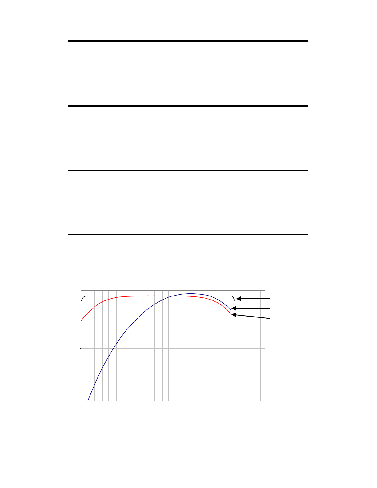
Frequency Weighting Filters
Frequency Weightings are where the Sound Pressure Level (SPL) is modified by
use of filtering. All Sonus Pocket Meters use electronic frequency weighting
filters between the standardised frequencies of 10Hz and 20,000Hz.
Depending on your instrument type (see Technical Specifications for further
details), the following standardised frequency weightings are available: -
‘A’ Weighting
The SPL is filtered in such a manner as to reflect the hearing response of a
human ear. The signal is progressively attenuated at the higher and lower ends
of the audible frequency range but much more attenuation occurs at the lower
end of the audible frequency range. Generally this is the most commonly used
frequency weighting.
‘C’ Weighting
The signal is progressively attenuated at the higher and lower ends of the
audible frequency range, however the attenuation at the lower end is much less
than with A Weighting. The response has a flat area between 200Hz and
1250Hz and has -3dB points at 31.5Hz and 8kHz. It is generally used for the
acoustic emissions of machinery and for peak sound levels.
‘Z’ Weighting (Zero) – (Models ‘E’ & ‘L’ Only)
Often referred to as the FLAT or LIN response, this weighting has a virtually flat
response over the entire audible frequency range.
Z Weighting
A Weighting
C Weighting

Page 10
Overload and Under Range Conditions
Overload Condition
An overload condition occurs when the peak signal starts to exceed the signal
handling capability of the pre-amplifier circuitry. If the noise source exceeds the
linear operating range of the range selected by 0.5dB then an overload
condition occurs and an overload indicator is displayed on your meter.
At 1kHz the overload condition occurs at 0.5dB above the top of each range for
all frequency weightings. The overload indicator will flash for a minimum of one
second or while the overload condition remains.
In such circumstances it is highly recommended you change to a higher range
with a lower sensitivity (i.e. less gain) as your meter will be out of specification.
An overload indication can occur in both Stop or Record Mode on ‘L’ and ‘E’
models and only in Record Mode for models ‘I’ and ‘B’.
All models have an overload latch indicator which can be viewed by scrolling
through the available parameters. Depending on whether an overload has
occurred or not, the overload latch screen will display either off the following: -
On models ‘I’ and ‘B’ if an overload has been latched it can be removed in Stop
Mode or Record Mode by resetting the parameters.
On models ‘L’ and ‘E’ instruments a latched overload can be removed in Stop
Mode by resetting parameters and if in Record Mode it is automatically
removed when the recording has been stopped.
Please be aware that the selected frequency weighting may attenuate the
displayed signal level below the overload triggering point but an overload can still
occur. This is because the overload operates from the unweighted input signal.
Note: In most case, if you see an overload indication on your sound meter, you
should discard the measurements taken, select a higher range and re-take the
measurements.
OVERLOAD
O.L. NO
O.L. YES

Page 11
Under Range Condition
An under range condition occurs when the noise source is more than 0.1dB
below the bottom of the range selected, at which point an under range indicator
will flash on the display of your meter. In such circumstances it is highly
recommended to change to a higher range with a higher sensitivity (i.e. more
gain) as your meter will be out of specification.
The under range indicator will flash for a minimum of one second or while the
under range condition remains.
Where the noise source is more than 0.5dB below the bottom of the selected
range, no value or under range warning is displayed.
Note: Under range displayed on your meter indicates that you should discard the
measurements, select a lower range and re-take your measurements.
**UR**
LAF --.-
 Loading...