

Page 1
WFS SERIES
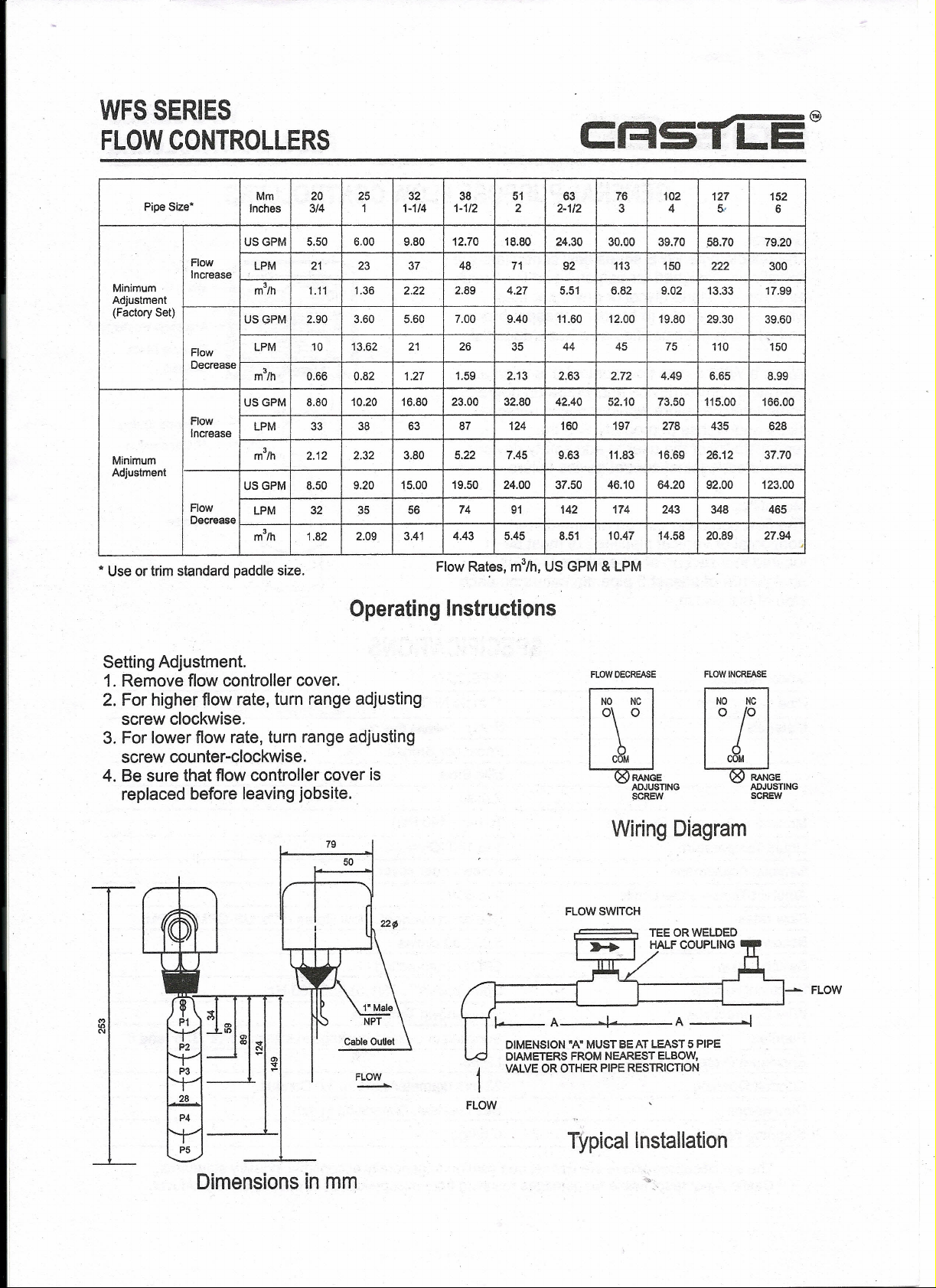
FLOW CONTROLLERS
C:RSTLE@
Pipe Size"
Minimum
Adjustment
(Factory Set)
Flow
Increase
Mm 20 25 32 38 51 63 76 102 127
Inches 3/4 1 1-1/4 1-1/2 2 2-1/2
USGPM
LPM 21 23 37 48 71
m3/h
USGPM
I
Flow
Decrease
Flow
Increase
Minimum
Adjustment
Flow
Decrease
*
Use or trim standard paddle size.
LPM 10
m3/h 0.66
USGPM
LPM 33
m3/h 2.12
USGPM
LPM
m3/h 1.82
5.50 6.00 9.80 12.70 18.80 24.30
92 113 150 222
1.11
1.36 2.22 2.89 4.27 5.51 6.82
2.90 3.60 5.60 7.00
13.62 21 26
0.82 1.27 1.59 2.13 2.63 2.72
8.80 10.20 16.80
38 63
2.32 3.80 5.22
8.50 9.20
32
15.00 19.50 24.00 37.50 46.10 64.20 92.00 123.00
35 56
2.09 3.41
23.00
87 124
74 91 142 174 243 348 465
4.43 5.45
9.40
35
32.80
7.45
11.60 12.00 19.80 29.30
44 45 75 110
42.40
160
9.63 11.83
8.51
Flow Rates, m3th, US GPM&LPM
Operating Instructions
3
30.00 39.70
52.10 73.50 115.00 166.00
197
10.47
4
9.02 13.33 17.99
4.49
278 435 628
16:69
14.58 20.89 27.94
5.-
.58.70 79.20
6.65 8.99
26.12
152
6
300
39.60
150
37.70
.I
Setting Adjustment.
1. Remove flow controller cover.
2. For higher flow rate, turn range adjusting
screw clockwise.
3. For lower flow rate, turn range adjusting
screw counter-clockwise.
4. Be sure that flow controller cover is
replaced before leaving jobsite.
79
50
FI.OW
---'"-
FLOW OECREASE
NO NC
\0
COM
Wiring Diagram
FLOW SWITCH
DIMENSION "AMMUST BE AT LEAST 5 PIPE
DIAMETERS FROM NEAREST ELBOW,
VALVE OR OTHER PIPE RESTRICTION
FLOW
RANGE
ADJUSTING
SCREW
FLOW INCREASE
~!
COM
RANGE
ADJUSTING
SCREW
- FLOW
P5
Dimensions in mm
Typical Installation
Page 2

C:r-ISTLE@
GENERAL PURPOSE FLOW CONTROLLERS
General,
The paddle type WFS series flow controllers are
specifically designed for use on liquid lines such
as water, ethylene glycol or any other fluid
which is not harmful to brass or phosper bronze
and which is not classified as a hazardous fluid.
When a WFS series flow controller is used as an
operating control device and where an operating
control device failure would result in personal
injury and/or loss of property, it is the
responsibility of the user to add safety devices
that protect against control device failure.
Mounting.
The flow controller can be mounted in a
horizontal or vertical pipeline but must be
located in a section of pipe where there is a
straight run of atleast 5 pipe diameters on each
side of the switch.
WFS SERIES-
FLOW CONTROLLERS
Cover
~~~~~~ Micro81W
Adjusting Screw
IU
J'~~~~f
Ik
Seesaw Plate,
Bellows
Balance Spring
1" Connection
SPECIFICATIONS
Model Number WFS-25-S
Pipe Connection 1" male NPT
Materials Brass
Maximum Operating Pressure
Liquid Temperature
Setpoint Adjustment
Ambient Temperature Limits
Flow rates
Bellow life
Switch Action
Electrical Ratings
Wire Connections
Paddles
Enclosure Protection Class
Conduit Opening
Dimensions
Shipping Weight
I
Stainless Steel 304
Phosphor Bronze
Mild Steel
Palstic
10 bar ( 140 Psi)
1 to 100° C
Screw under cover.
o
to 60°C
See chart overleaf. Flow Rates m3/h, US GPM&LPM
5.00,000 cycles
SPOT, Snap-acting.
Upto 250VAC, 15(7.5) A, 50/60 Hz
Screw-down Terminals
Supplied in 5-piece package in sizes of 1",2",3",5" and 6"
I.P 55
22 mm diameter hole for%"Conduit.
See overleaf. Dimension in mm. '
O.6/kgs
The specifications above are normal and confirm to generally acceptable industry standards.
Castle is not responsible for damages resulting from misapplication or misuse of it's products.
 Loading...