

Page 1
CASTLE, INC
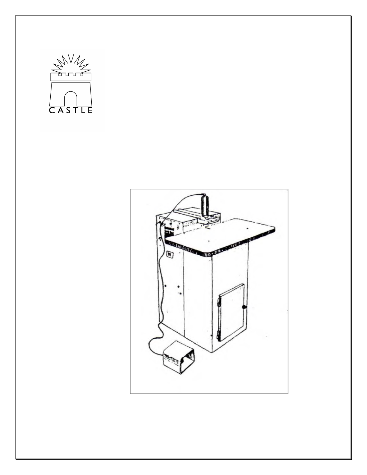
MORTISE MACHINE
MODEL TSM-20
O
PERATOR’S
Revised: October 2, 2010
M
ANUAL
Page 2

1.0
CASTLE, INC.
MORTISE MACHINE MODEL TSM-20
OPERATOR'S MANUAL
TABLE OF CONTENTS
GETTING STARTED..................................................................................................................... 1
1.1
Warning...................................................................................................................................... 1
1.2
Check for Damage ..................................................................................................................... 1
1.3
Package Contains ...................................................................................................................... 1
1.4
Machine Requirements ............................................................................................................. 1
Page #
2.0
3.0
4.0
5.0
6.0
GLOSSARY OF TERMS ................................................................................................................ 1
2.1
Carriage...................................................................................................................................... 1
2.2
Control Panel/Limit Switches .................................................................................................. 2
2.3
Drive Cylinder ........................................................................................................................... 2
2.4
Foot Pedal and Guard ............................................................................................................... 2
2.5
Hold Down Cylinder & Guard................................................................................................. 2
2.6
Safety Buttons ............................................................................................................................ 2
MACHINE OPERATION .............................................................................................................. 3
3.2
Starting the Application............................................................................................................ 3
MACHINE ADJUSTMENTS......................................................................................................... 3
4.1
Feed Rate Adjustment............................................................................................................... 3
4.2
Carriage Height Adjustment .................................................................................................... 3
MACHINE MAINTENANCE........................................................................................................ 4
5.1
Motors......................................................................................................................................... 4
5.2
Tooling Changes ........................................................................................................................ 4
TROUBLE SHOOTING ................................................................................................................. 5
TSM-20 Operator’s Manual Page ii
Page 3

1.0 GETTING STARTED
1.1 Warning
The Castle Tool Mortise Machine was designed with operator safety as a priority. DO NOT ATTEMPT
TO OPERATE THIS MACHINE UNTIL ALL INSTRUCTIONS HAVE BEEN READ.
1.2 Check for Damage
Your Castle Tool Mortise Machine was carefully prepared for shipment at our factory. Upon receipt at
your plant, carefully inspect the machine for damage. Immediately report any damage to the freight
company, your dealer, and Castle, Inc.
1.3 Package Contains
Warranty Card (Must be returned for warranty activation)
Operator’s Manual
Router Wrenches (4)
Bit Gage
Model TSM-20 Mortise Machine
1.4 Requirements
110 V AC, 20 AMP Power Supply
Air Source (80 psi minimum)
2.0 GLOSSARY OF TERMS
The major components of the model TSM-20 and a brief description of their functions are as follows:
2.1 Carriage
The carriage is the orange A-Frame structure inside the machine. Both the router and the drill motors are
mounted to this carriage. There are also two micro switches mounted at the top of the carriage. The micro
switch mounted towards the rear of the machine stops the travel of the carriage during its routing cycle
and starts the drilling cycle. The micro switch mounted towards the front of the machine stops the travel
of the carriage during the drilling cycle.
TSM-20 Operator’s Manual
1
Page 4

2.2 Control Panel/Limit Switches
The control panel is the box that is mounted on the left side of the machine, when viewed from the front.
It houses the power switch, speed control and air input port. Inside the machine mounted on the back of
the control panel are two micro switches. The micro switch at the top of the control panel tells the
machine when it is in the neutral position (no bits are out). The micro switch on the bottom of the control
panel is triggered by the safety buttons at the face of the machine. If those buttons are not depressed or if
they fail to trigger this switch, the food pedal will have no effect on the machine.
2.3 Drive Cylinder
The drive cylinder is the long narrow cylinder that is connected between the carriage and the inside front
portion of the machine. The drive cylinder moves the carriage towards the rear of the machine on the
routing stroke and towards the front of the machine on the drilling stroke.
2.4 Foot Pedal and Guard
The foot pedal is mounted inside the orange guard to prevent accidental cycling of the machine. The foot
pedal when depressed will start the cycling of the machine only when the safety buttons are pushed.
2.5 Hold Down Cylinder and Guard
The large cylinder and yellow bracket located on top of the machine. The hold down cylinder acts as a
clamp during the machines cycle preventing material shift during cycling. The hold down guard helps to
safeguard against accidentally contacting moving parts.
2.4 Safety Buttons
The two allen head bolts protruding slightly on either side of the drill hole at the front of the machine.
The material to receive the Castle Pocket must fully depress at least one of these buttons before the
machine will cycle.
3.0 MACHINE SETUP & OPERATION
Now you’re ready to get started with your Castle TSM-20 machine.
3.0.1 Check that the power switch is in the “OFF” position.
3.0.2 Check that the carriage is in the neutral position. Neither the router bit nor the drill bit
should be protruding from the machine.
TSM-20 Operator’s Manual
2
Page 5

3.0.3 Place the foot switch in front of the machine in an accessible, safe location.
3.0.4 Connect the machine to a clean air supply. It is strongly recommended that an inline
filter/water trap be used. The Model TSM-20 has internal air pressure regulator that is
preset to 80 psi. Using an air supply of less than 80 psi will result in insufficient
clamping force which can cause material shifting and possible injury to the operator.
3.0.5 Place the material in which you will cut a Castle Pocket under the hold down cylinder
and firmly push the material against the face of the machine. Position the material so that
the desired pocket location is centered under the hold down cylinder guard.
3.0.6 Turn the power switch to the “ON” position.
3.0.7 Press and release the foot switch to activate a pocket cycle. When the cycle has been
completed the clamp will automatically release the material unless pressure is maintained
on the footswitch.
3.0.8 In the event the machine fails to function properly, refer to the “Troubleshooting” section
of this manual or call your dealer or Castle, Inc. for assistance.
4.0 MACHINE ADJUSTMENTS
The Castle, Inc. Model TSM-20 was designed to be used on a wide variety of materials. You will find
that the machine performs equally well in hardwoods or pressboard materials and in thicknesses from ½”
to ¾”.
4.1 Feed Rate Adjustment
When switching between materials of different density it may be necessary to adjust the router feed rate
to achieve optimum performance. In general, the desired feed rate is slower for harder materials. The
feed rate adjustment knob is located to the left of the power switch on the outside of the control panel.
Rotating the knob clockwise slows the router feed rate, and rotating it counter clockwise increases the
router feed rate.
4.2 Carriage Height Adjustment.
The carriage height as set at the factory will perform well in almost all material thicknesses. However
you may find it useful on occasion to raise or lower the carriage thereby changing the depth of the pocket
and location of the pilot hole. For example when mortising ½” thick material it may be necessary to
lower the carriage to prevent the router bit from cutting through the top surface of the material.
Conversely, when cutting a pocket in material thicker than one inch, raising the carriage will relocate the
pilot hole exit point closer to the center of the material.
4.2.1.1 Loosen the bolts that are threaded into the brass carriage bearings
4.2.1.2 Remove the bolts at the rear of the carriage bearing jacks.
4.2.1.3 Raise or lower the carriage bearing jacks to the desired height.
4.2.1.4 Reinstall and tighten the rear bolts in the holes closest to the desired position.
4.2.1.5 Tighten the bolts that are threaded into the brass carriage bearings
TSM-20 Operator’s Manual
3
Page 6

4.2.1.6 Check that the drill bit is centered on the hole in the face of the machine and that there
are no interference problems before operating the machine.
5.0 MAINTENANCE
The Model TSM-20 requires very little maintenance. However, to ensure productivity and longevity of
your Castle, Inc. Pocket Machine it is essential that a few simple steps are followed. How often these
steps are to be performed is directly proportional to the amount of hours the machine is operated each
day. As a general rule operators should get in the habit of visually checking the machine at lease prior to
the start of each shift.
5.1 Motors
The TSM-20 uses two Porter-Cable motors (models 3102 and 6902). Because of the enclosed
environment that these motors are functioning in, it is important that the maintenance guidelines provided
in the Porter-Cable instruction manuals are strictly adhered to. Periodically – at least once per hour of
operation – blow out all air passages on both motors with compressed air. CAUTION: ALWAYS WEAR
SAFETY GLASSES WHILE USING COMPRESSED AIR!
Note: To prolong motor life and to avoid costly down-time it is strongly recommended that a dust
collection system be used. A port on the left side of the machine has been provided for this purpose.
5.2 Tooling Changes
Before attempting to service any part of the TSM-20 ensure that the power switch is in the “OFF”
position, the machine is not plugged in and air is disconnected from the machine.
5.2.1 Router Motor (Porter-Cable #6902) Removal
5.2.1.1 Unplug both motors from the control board.
5.2.1.2 Note the position of the power switch and power cord prior to removal of the motor. It is
imperative that the power switch and cord are placed in the same position when reinstalling.
5.2.1.3 Loosen the lever nut located on the left hand side – as seen from the rear of the machine – of the
carriage at the front of the steel sleeve that holds the motor. Be sure to hold the base of the motor
with one hand as it will slide down as the pressure is released.
5.2.1.4 Replace the router bit following the Porter-Cable router instruction manual provided.
5.2.1.5 Using the Bit Gage provided set the gage on top of the collet nut and adjusts the bit height so that
the top of the bit is even with the line marked with the “R”.
5.2.1.6 Reinstall the motor in the reverse order of the above taking care to insure that the motor is
inserted fully into the motor sleeve.
5.2.2 Drill Motor (Porter-Cable #3102) Removal
5.2.2.1 Unplug both motors from the control board.
5.2.2.2 Loosen the “T” Handle located near the top of the carriage to the left – looking in from the rear
of the machine – of the drill.
5.2.2.3 While grasping the motor at its base, pull the motor out.
TSM-20 Operator’s Manual
4
Page 7

5.2.2.4 Replace the drill bit in accordance with the Porter-Cable instruction manual with the following
exceptions.
5.2.2.4.1 Insert the drill bit into the brass bushing (Castle PN MT04)
5.2.2.4.2 Place the aluminum bit gage on top of the collet nut.
5.2.2.4.3 Adjust the depth of the drill bit so that the tip of the bit is aligned with the line marked “D”.
5.2.2.5 Reinstall the motor making certain that the motor is all the way forward against the motor mount
and pulled down in the motor saddle.
6.0 TROUBLESHOOTING
PROBLEM PROBABLE CAUSE POSSIBLE SOLUTION(S)
Nothing happens when power
switch is turned on.
Machine does not cycle when
foot pedal is depressed
Clamp comes down but machine
does not cycle
Machine routs pocket but does
not drill hole and clamp does not
release
Pilot hole does not go through to
pocket
Machine routes and drills but
does not finish cycle
No Power Verify machine is
plugged in
Check power source
Safety buttons not
depressed
No air supply
Flow control closed
Router not running
Push material against
safety buttons
Connect to air
Open flow control
Plug in router
Turn on router
Drill motor not running
Drill motor over
tightened
Plug in drill motor
Turn on drill motor
Loosen “T” handle –
check for damage
Pocket is not cut far
enough
Drill bit not set at correct
depth
Adjust router stop switch
and /or router stop bolt
Reinstall drill bit using
bit gage
Low air pressure Check line pressure
Check internal regulator
TSM-20 Operator’s Manual
5
 Loading...