

Page 1
PHOENIX-60
PHOENIX-60PHOENIX-60
PHOENIX-60
™
By Castle Creations
60 amp Brushless Sensorless Speed Control
PHOENIX-60™ User Guide Page 1 of 6 Rev 5-date 11/11/03
This document, Phoenix-60™ software, and Phoenix-60™ PCB layout are all Copyright 2002-2003 by Patrick del Castillo and Castle Creations
Warning! High power motor systems can be very dangerous! High currents can heat wires and
batteries, causing fires and burning skin. Follow the wiring directions carefully! Model aircraft
equipped with high power motors can kill. Always fly at a sanctioned field. Never fly over or near
spectators. Even though this controller is equipped with a safety arming program, you should still use
caution when connecting the main battery.
1.0 Features of the Phoenix-60™:
• Extremely Low Resistance (.0013 ohms)
• High rate adjustable switching (PWM)
• Up to 60 amps continuous current with proper air flow, 80
amps surge
• Five to ten cells with four micro servos
• Up to twelve cells with three micro servos
• Twenty cells MAX (with BEC disabled)
• Dynamic braking ensures folding props fold promptly
• BEC (3A) provides power to receiver and servos -
eliminates separate receiver battery
• User Programmable Features:
• Low-voltage cutoff
• Over-current Protection
• Brake Type
• Throttle Range – fi xed/self-adjusting/go vernor
• Timing Advance
• Cutoff Type
• Soft Start ramp up
• Switching Frequency
• Runs motor in forward OR reverse
• Auto Motor Cutoff with Re set
• Safe “power on” arming program ensures motor will not
accidentally turn on
• Low torque “soft start” prevents damage to fragile
gearboxes
• Auto shut down when signal is lost or radio interference
becomes severe
2.0 Wiring Your Phoenix-60™:
Tools required:
Wire cutters Wire strippers (optional) Soldering Iron (25-40)
Parts required:
Solder (rosin core “electronic” solder) Battery connector
2.1 Servo Ratings with BEC Enabled
Servo Type 5-6 cells 7-8 cells 9-10 cells 11-12 cells
Standard (micro) servos 5 5 4 3
High Torque servos 4 4 3 2
2.2 Adding the Battery Connector
The battery connector is attached to the side of the controller that has only two power wires, and also has the
radio connector. Cut the wires to the length you require on the battery side. Strip off of the wire insulation to
expose just enough wire to attach the battery connector. (Note: if you do not have a pair of wire strippers,
you can use a modeling knife to carefully cut through the insulation around the wire. Then the insulation
should easily pull off the wire.) Attach the battery connector to the wires ENSURING THAT THE
POLARITY (red wire to battery red wire, black wire to battery black wire) IS CORRECT, following the
instructions for the battery connector.
IMPORTANT NOTE: YOU MUST BE SURE THAT THE POLARITY IS CORRECT WHEN
CONNECTING THE SPEED CONTROLLER. Incorrect polarity could permanently damage the controller.
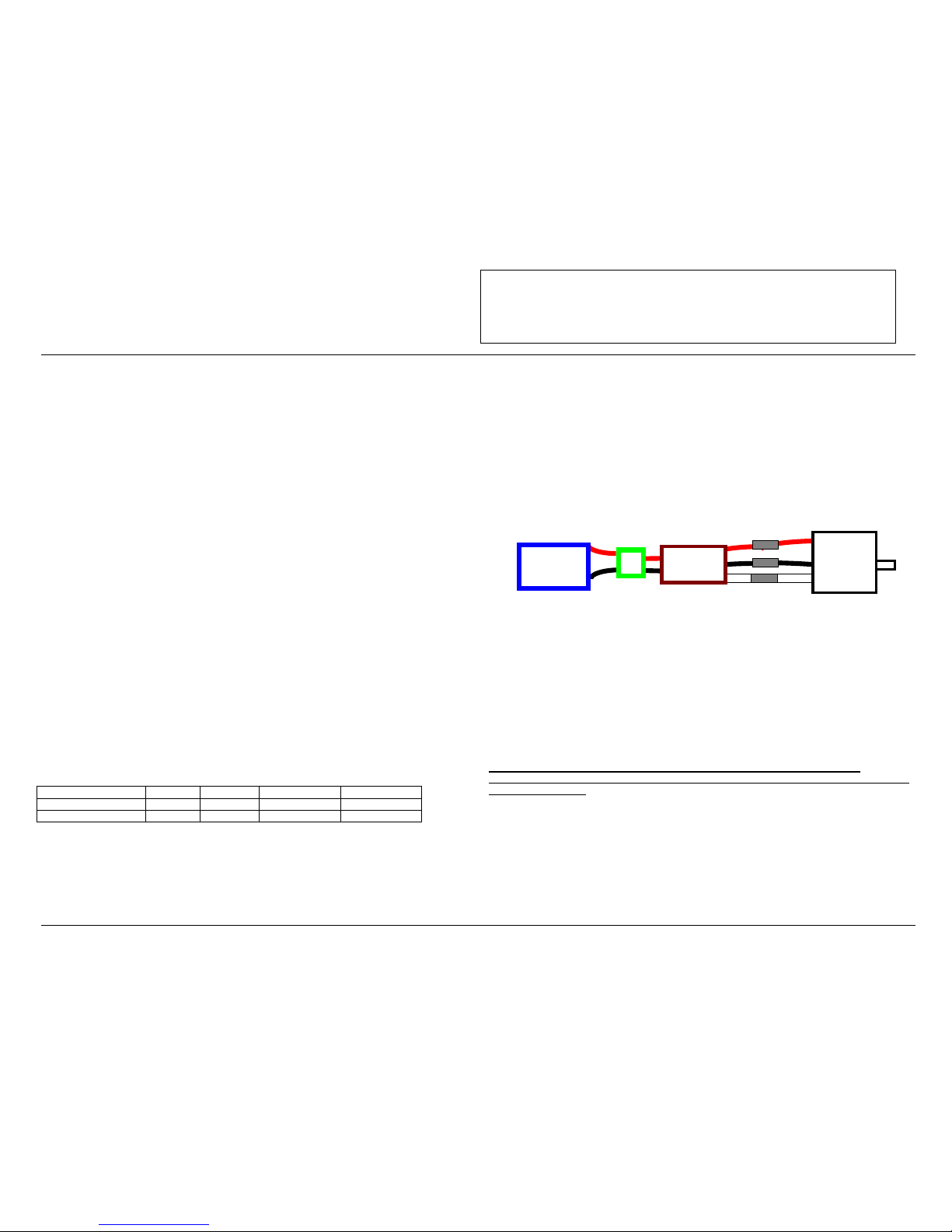
2.3 Connecting the Motor
The motor is connected to the side of the controller that has THREE power wires. Cut the wires to the length
you require on the motor side. DO NOT CUT the wires leadin g from the motor. Strip the wire insulation to
expose just enou gh wire to solder th e wires to the motor t erminals. There should be three wires extending
from the motor. Connect the three speed con trol wires to the t hree motor wires. Align the wires carefully
and solder to the motor wires. Ensure that all connections (battery and motor) are correctly polarized.
2.4 Reversing Rotation
Bench test the motor connections noting the rotation of the motor. To change the rotation of the motor, swap
ANY two motor wire connections.
Battery Connector Phoenix-60™ Motor
Fig 1: Motor wiring diagram
2.5 Connecting the Receiver
Connect the receiver lead (the three color twisted wires with a connector on the end) to the throttle channel
on your receiver (usually channel 3). Do not connect a battery to the receiver, as the Phoenix-60™ will
supply power to the receiver and servos through the receiver connector. If you are using more than ten cells,
you must use a separate receiver battery. See the section 4.0 (under the heading BEC) for instructions on
disabling the BEC to use a separate receiver battery.
Older AirTronics systems require a minor change to the wiring in the receiver connector supplied with the
speed controller. Reverse the red (power) and brown (ground) wires in the connector plug so that the plug is
orange/brown/red. Use a knife blade to lift the retention tabs on the connector plug to remove the red and
brown wires. Insert the wires back into the plug and press down the retention tab.
3.0 Flying with Your Phoenix-60™:
ALWAYS PERFORM A RANGE CHECK BEFORE FLYING WITH ANY NEW SPEED
CONTROLLER! PERFORM YOUR RANGE CHECK AT FULL THROTTLE, HALF THROTTLE
AND NO THROTTLE.
Initialization sequence:
1. Connect the speed controller receiver connector to the proper channel on your receiver (usually channel 3)
2. Turn on your transmitter.
3. Connect the main power battery to the speed controller.
4. The speed controller will remain disarmed (will not operate) until it sees more than four seconds of
“brake” throttle. Move the throttle arm to the lowest position on your transmitter, wait at least four
seconds, an d then test the controller to make sure tha t the throttle operates.
5. Go fly!
6. If the BEC cutoff occurs before you land, you may restart the motor and use low throttle if necessary by
moving the throttle stick all the way down (to the brake position) and then throttling back up. BEC cutoff
will occur again if the voltage drops too low.
Phoenix-60™
Page 2

PHOENIX-60
PHOENIX-60PHOENIX-60
PHOENIX-60
™
By Castle Creations
60 amp Brushless Sensorless Speed Control
PHOENIX-60™ User Guide Page 2 of 6 Rev 5-date 11/11/03
This document, Phoenix-60™ software, and Phoenix-60™ PCB layout are all Copyright 2002-2003 by Patrick del Castillo and Castle Creations
Warning! High power motor systems can be very dangerous! High currents can heat wires and
batteries, causing fires and burning skin. Follow the wiring directions carefully! Model aircraft
equipped with high power motors can kill. Always fly at a sanctioned field. Never fly over or near
spectators. Even though this controller is equipped with a safety arming program, you should still use
caution when connecting the main battery.
4.0 Using the Features of Your Phoenix-60™
BEC - The BEC power is supplied to the receiver and servos through the receiver connector wires. If you
wish to disable the BEC and use a separate receiver battery (required for the use of more than twelve cells),
you must first cut the red wire in the trio of receiver wires. Simply use a pair of wire cutters to remove a
short section of the red wire near the receiver connector, and be sure to insulate the cut wire with a bit of
electrical ta pe. Then you may sa fely use a battery with your receiver.
Brake - moving the transmitter throttle stick to the bottom position enables the prop brake.
Cutoff - The motor cutoff will occur when the input battery voltage drops below the programmed cutoff
voltage (factory preset at 5.0V) for more than one half second. Once motor cutoff has occurred, moving the
throttle to the b raking positi on (full off) can re-arm th e controller. This will allow restart of the motor at low
throttle after cutoff has occurred. WARNING: Repeated restarting of the motor may drain the battery
to a point where the radio receiver will stop operating, resulting in a loss of control of the model.
Loss of Transmitter Signal, or excessive radio noise cutoff - Motor cutoff will also occur if the signal from
the transmitter is lost, or if the radio noise becomes excessive. After radio connection has been reestablished,
moving the throttle to the braking position (full off) for one second can restart the motor.
Safe Power Up - The Safe Power up feature is a “finger saver”, designed to prevent the motor from starting
accidentally on power up. To arm the controller, the transmitter stick must be held in the “Brake” position
(all the way down) for at least four seconds. Until the controller is armed, it will not provide any power to
the motor, regardless of where the throttle stick on your transmitter is positioned. Before flying your
model, be sure to “blip” the throttle to ensure that the controller is armed.
LED – The LED is used for programming the features on the Phoenix-60™. Once armed, the LED also
provides an indication that the controller has reached full throttle by lighting solid when full throttle is
reached. If the unit is in Auto-Calibrating Throttle mode (program setting 4-1) then you may see full throttle
LED indication before the stick is in the full up position. Simply continue moving the stick to full up. The
controller will detect the high stick travel and adjust full throttle accordingly.
5.0 Troubleshooting
Everything is hooked up correctly, the BEC (receiver and servos) works, but the throttle does not
work.
The controller is not seeing the four seconds of “dead space” (low throttle) and is not arming. Try moving
your throttle stick all the way down, and moving the trim all the way down. Wait for four seconds and try the
throttle again. If it still does not arm, you may need to reverse the throttle control on your transmitter (see
your radio documentation). You may also check to make sure that your endpoint adjustments on your radio
(if it has t hem) are set all th e way open.
Every time I throttle all the way up, the controller “cuts off” after a few seconds, even with fresh
charged batteries.
The controller will automatically shut d own the motor if the battery voltage falls below th e programmed
voltage cutoff (factory preset at 5.0V) for more than half a second. This is to protect your airplane from a
loss of control caused by too low a voltage at the receiver. If the cutoff is kicking in with fresh charged
batteries, it means that the voltage is dropping very quickly. This is usually an indication of a motor that is
drawing too much current for the batteries to handle. Try using a smaller prop on the motor, or using
batteries with a higher rating (for example, if you are using 800AR cells, you might try going to 1000SCR
cells.)
The LED comes on when I throttle up.
This is normal. The LED comes on when full throttle has been reached. If the unit is in Auto-Calibrating
Throttle mode (program setting 4-1) then you may see full throttle LED indication before the stick is in the
full up position. Simply continue moving the stick to full up. The controller will detect the high stick travel
and adjust full throttle accordingly.
Nothing seems to work, receiver and servos are dead, and the throttle is dead.
Check all connections to ensure that they are correct, and that the polarity (+/-) connections are correct. If
everything is correctly connected, and the receiver and servos still do not work, contact the dealer where you
purchased your Phoenix-60™ or Contact
Castle Creations directly. (See info below)
6.0 Contact / Warranty Information
Your Phoenix-60™ is warranted for one(1) year from date of purchase to be free from manufacturing and
component defects. This warranty does not cover abuse, neglect, or damage due to incorrect wiring, over
voltage, or overloading. If you have any questions, comments, or wish to return your Phoenix-60™ for
warranty or non-warranty repair/replacement contact
Castle Creations at:
Castle Creations Email: info@castlecreations.com
402 E. Pendleton Ave. Fax: (785) 883-4571
Wellsville, KS 66092 Website: http://www.castlecrea tions .com
Tel: (785) 883-4519
7.0 Phoenix-60™ Programming Features
Programming the Phoenix-60™
Programming the Phoenix-60™ is as simple as answering a few questions. The Phoenix-60™ asks questions
by flashing a setting number, followed by the possible setting values. There are eight settings that can be
programmed in the Phoenix-60™: 1) Cutoff voltage, 2) Current Limiting, 3) Brake Type, 4) Throttle Type, 5)
Timing Advance, 6) Cutoff Type, 7) Soft Start, and 8) PWM Switching Frequency.
As the programmer, you must answer “yes” or “no” to the setti ng values as they are presented by th e
Phoenix-60™. Th e setting values are “flashed” out by the LED. Answering “no” to a setting value will
cause the Phoenix-60™ to ask for t he next value. Answerin g “yes” to a setting value will store that setting in
the Phoenix-60™s permanent memory. After a setting is stored, the Phoenix-60™ will continue to ask about
other settings until all settings have been stored. NOTE: If you answer “no” to all values for a particular
setting, the Phoenix-60™ will keep whatever value had been previously programmed. Only by answering
“yes” to a value will the Ph oenix-60™ store/ change that value.
When answering a question, you will need to move the transmitter stick to the yes (full on throttle) position
or the no (full off throttle) position and keep it there for about 5 seconds. When the Phoenix-60™ has
accepted your answer, it will flash the LED rapidly. After the LED starts it’s rapid flashing, move the throttle
stick to the middle position to confirm that you are ready for the Phoenix-60™ to ask the next question.
You are not required to continue through all eight programming options. For example, if you wish only to
change the Cutoff Voltage (option 1) then after programming that setting you can disconnect power from the
Phoenix-60™ and proceed to the arming sequence (see Section 3.0). Disconnecting the controller in the
middle of programmin g simply retains th e values for the remain ing programming op tions that were
previously set up.
Page 3

PHOENIX-60
PHOENIX-60PHOENIX-60
PHOENIX-60
™
By Castle Creations
60 amp Brushless Sensorless Speed Control
PHOENIX-60™ User Guide Page 3 of 6 Rev 5-date 11/11/03
This document, Phoenix-60™ software, and Phoenix-60™ PCB layout are all Copyright 2002-2003 by Patrick del Castillo and Castle Creations
Warning! High power motor systems can be very dangerous! High currents can heat wires and
batteries, causing fires and burning skin. Follow the wiring directions carefully! Model aircraft
equipped with high power motors can kill. Always fly at a sanctioned field. Never fly over or near
spectators. Even though this controller is equipped with a safety arming program, you should still use
caution when connecting the main battery.
8.0 Entering Programming Mode
The Phoenix-60™ software is designed to make it difficult to accidentally enter programming mode,
therefore it may seem like a long process to enter programming mode. This is to prevent en tering
programming mode while preparing to fly or while in flight. To enter programming mode, follow the steps
below:
8.1 Verify Normal Operation
If this is the first time the Phoenix-60™ has been used, it is important to verify that the Phoenix-60™
operates normally with your transmitter otherwise programming may not function properly. Follow the
instructions in section 3.0 Initialization Sequence (steps 1-4). Once you have verified that the Phoenix-60™
operates normally, proceed to 8.2 below. If the Phoenix-60™ does not operate properly, see section 5.0,
Troubleshooting.
8.2 Enter Programming Mode
8.2.1 Remove battery power from the Phoenix-6 0™.
8.2.2 Move the transmitter stick to the top position (normally full “On”).
8.2.3 Reconnect battery power to the Phoenix-60™.
8.2.4 After approximately 2 seconds, the Phoenix-60™ will emit a short tone, and the LED on the
Phoenix-60™ should flash a short, single flash followed by a pause.
Phoenix-60™ responds: flash – pause
8.2.5 Move your transmitter stick to the middle position.
8.2.6 After approximately 2 seconds, the Phoenix-60™ will emit a short tone, and the LED on the
Phoenix-60™ should flash a short, double flash followed by a pause.
Phoenix-60™ responds: flash – flash – pause
8.2.7 Move your transmitter stick to the top position again.
8.2.8 After approximately 2 seconds, the Phoenix-60™ will emit a short tone, and the LED on the
Phoenix-60™ should flash a short, triple flash followed by a pause.
Phoenix-60™ responds: flash – flash – flash – pause
8.2.9 Move your transmitter stick back to the middle position again.
8.2.10 After approximately 2 seconds, the Phoenix-60™ will emit four short tones, and the LED on the
Phoenix-60™ will start a flash sequence of a single flash followed by another single flash,
followed by a long pause.
Phoenix-60™ responds: flash – flash – pause
8.2.11 The Phoenix-60™ is now in programming mode.
8.2.12 Proceed to Section 9.0 – Programming the Phoenix-60™
9.0 Programming the Phoenix-60™
Important Note: When answering a question, you will need to move the transmitter stick to the yes (full
“On” throttle) position or the no (full “Off” throttle) position and keep it there for about 2 seconds. When the
Phoenix-60™ has accepted your answer, it will flash the LED rapidly. After the LED starts it’s rapid
flashing, move the throttle stick to the middle position to confirm that you are ready for the Phoenix-60™ to
ask the next question.
If you wish to re-program only some of the features you do not need to continue through the programming
steps for the remaining settings. Once you have programmed each of the features you wish to change and the
Phoenix-60™ has confirmed the selection, instead of returning to mid-throttle for the next question,
disconnect battery power, re-connect power, and arm the speed control as normal (see Section 3.0).
*Factory default settings are indicated by an asterisk in the option listings below.
9.1 Programming Setting 1 –Cutoff Voltage
Setting Recommended for use with: Setting Recommended for use with: _________________
Option 1: 4.0V cutoff voltage 5 cell NiCad or NiMH packs Option 4: 7.2V cutoff voltage 9-12 cell NiCad or NiMH packs, or 3 cell Lithium packs
Option 2: 5.0V cutoff voltage* 6-8 cell NiCad or NiMH packs, or 2 cell Lithium packs Option 5: 9.0V cutoff voltage 12-14 cell NiCad, 12-20 cell NiMH, or 4 cell Lithium packs
Option 3: 6.0V cutoff voltage 7-10 cell NiCad or NiMH packs Option 6: 12.0V cutoff voltage 20 cell Nicad packs, or 4 cell Lithium packs
Phoenix-60™ Displays: Programming Question Asked: Your Response: Phoenix-60™ Action: Your Action:
Yes – Thro ttle stick in up position
Stores selection. Flashes rapidly to confirm receipt of
your respons e.
Return Tx stick to center and proceed to next setting–Current Limiting
(9.2 below)
1 flash – short pause – 1 flash – long pause Setting 1 (cutoff voltage), Option 1
(4.0V)?
No – Throttle stick in off position
Flashes rapidly to confirm receipt of your response. Return Tx stick to center and proceed to next option for this setting
Yes – Thro ttle stick in up position
Stores selection. Flashes rapidly to confirm receipt of
your respons e.
Return Tx stick to center and proceed to next setting–Current Limiting
(9.2 below)
1 flash – short pause – 2 flashes – long pause Setting 1 (cutoff voltage), Option 2
(5.0V)?
No – Throttle stick in off position
Flashes rapidly to confirm receipt of your response. Return Tx stick to center and proceed to next option for this setting
Yes – Thro ttle stick in up position
Stores selection. Flashes rapidly to confirm receipt of
your respons e.
Return Tx stick to center and proceed to next setting–Current Limiting
(9.2 below)
1 flash – short pause – 3 flashes – long pause Setting 1 (cutoff voltage), Option 3
(6.0V)?
No – Throttle stick in off position
Flashes rapidly to confirm receipt of your response. Return Tx stick to center and proceed to next option for this setting
Page 4

PHOENIX-60
PHOENIX-60PHOENIX-60
PHOENIX-60
™
By Castle Creations
60 amp Brushless Sensorless Speed Control
PHOENIX-60™ User Guide Page 4 of 6 Rev 5-date 11/11/03
This document, Phoenix-60™ software, and Phoenix-60™ PCB layout are all Copyright 2002-2003 by Patrick del Castillo and Castle Creations
Warning! High power motor systems can be very dangerous! High currents can heat wires and batteries, causing
fires and burning skin. Follow the wiring directions carefully! Model aircraft equipped with high power motors can kill.
Always fly at a sanctioned field. Never fly over or near spectators. Even though this controller is equipped with a safety
arming program, you should still use caution when connecting the main battery.
Phoenix-60™ Displays: Programming Question Asked: Your Response: Phoenix-60™ Action: Your Action:
Yes – Thro ttle stick in up position
Stores selection. Flashes rapidly to confirm receipt of
your respons e.
Return Tx stick to center and proceed to next setting–Current Limiting
(9.2 below)
1 flash – short pause – 4 flashes – long pause Setting 1 (cutoff voltage), Option 4
(7.2V)?
No – Throttle stick in off position
Flashes rapidly to confirm receipt of your response. Return Tx stick to center and proceed to next option for this setting
Yes – Thro ttle stick in up position
Stores selection. Flashes rapidly to confirm receipt of
your respons e.
Return Tx stick to center and proceed to next setting–Current Limiting
(9.2 below)
1 flash – short pause – 5 flashes – long pause Setting 1 (cutoff voltage), Option 5
(9.0V)?
No – Throttle stick in off position
Flashes rapidly to confirm receipt of your response. Return Tx stick to center and proceed to next option for this setting
Yes – Thro ttle stick in up position
Stores selection. Flashes rapidly to confirm receipt of
your respons e.
Return Tx stick to center and proceed to next setting–Current Limiting
(9.2 below)
1 flash – short pause – 6 flashes – long pause Setting 1 (cutoff voltage), Option 6
(12.0V)?
No – Throttle stick in off position
Flashes rapidly to confirm receipt of your response.
Maintains previous setting for cutoff voltage (no change)
Return Tx stick to center and proceed to next setting-Current Limiting
(9.2 below)
9.2 Programming Setting 2 –Current Limiting
NOTE: Change this setting at your own risk! Damage to the controller as a result of over current is NOT covered by the manufacturer’s warranty. Only experienced modelers should use this programming feature. Current limiting
describes the reaction of the Phoenix-60™ when an over-current condition is detected. There are five options:
Option 1: Very sensitive (Very low over-current threshold, will rapidly shut-down) Option 4: Insensitive (High over-current threshold, will shut down after a slight delay)
Option 2: Sensitive (Low over-current threshold, will rapidly shut-down) Option 5: Over current disabled (Over current detection disabled)
Option 3: Standard * (Moderate over-current threshold, will shut down after a slight delay)
Phoenix-60™ Displays: Programming Question Asked: Your Response: Phoenix-60™ Action: Your Action:
Yes – Thro ttle stick in up position
Stores selection. Flashes rapidly to confirm receipt of
your respons e.
Return Tx stick to center and proceed to next setting–Brake Type (9.3
below)
2 flashes - s hort pause –1 flash – lo ng pause Setting 2 (cur rent limiting), Opt ion 1
(Very sens itive)?
No – Throttle stick in off position
Flashes rapidly to confirm receipt of your response. Return Tx stick to center and proceed to next option for this setting
Yes – Thro ttle stick in up position
Stores selection. Flashes rapidly to confirm receipt of
your respons e.
Return Tx stick to center and proceed to next setting–Brake Type (9.3
below)
2 flashes - short pause – 2 flashes – long
pause
Setting 2 (cur rent limiting), Op tion 2
(Sensitive)?
No – Throttle stick in off position
Flashes rapidly to confirm receipt of your response. Return Tx stick to center and proceed to next option for this setting
Yes – Thro ttle stick in up position
Stores selection. Flashes rapidly to confirm receipt of
your respons e.
Return Tx stick to center and proceed to next setting–Brake Type (9.3
below)
2 flashes - short pause – 3 flashes – long
pause
Setting 2 (cur rent limiting), Op tion 3
(Standard)?
No – Throttle stick in off position
Flashes rapidly to confirm receipt of your response. Return Tx stick to center and proceed to next option for this setting
Yes – Thro ttle stick in up position
Stores selection. Flashes rapidly to confirm receipt of
your respons e.
Return Tx stick to center and proceed to next setting–Brake Type (9.3
below)
2 flashes - short pause – 4 flashes – long
pause
Setting 2 (cur rent limiting), Op tion 4
(Insensitive )?
No – Throttle stick in off position
Flashes rapidly to confirm receipt of your response. Return Tx stick to center and proceed to next option for this setting
Yes – Thro ttle stick in up position
Stores selection. Flashes rapidly to confirm receipt of
your respons e.
Return Tx stick to center and proceed to next setting–Brake Type (9.3
below)
2 flashes - short pause – 5 flashes – long
pause
Setting 2 (cur rent limiting), Op tion 5
(Disable d)?
No – Throttle stick in off position
Flashes rapidly to confirm receipt of your response.
Maintains p revious set ting for Current Limiting (no
change).
Return Tx stick to center and proceed to next setting – Brake Type
(9.3 below).
9.3 Programming Setting 3 – Brake Type
Delayed brake provides a 4-second delay before braking occurs. Soft brake provides 50% of full braking power; hard brake is 100% braking power. Hard brake should only be used on 10 cells or less.
Option 1: Soft delayed brake * General aircraft use, with fixed or folding prop Option 4: Hard brake, no delay Competition use where a very short brake delay is required
Option 2: Hard delayed brake Direct drive applications where more braking power is required Option 5: Brake Disabled Helicopters
Option 3: Soft brake, no delay Competition use where a very short brake delay is required
Phoenix-60™ Displays: Programming Question Asked: Your Response: Phoenix-60™ Action: Your Action:
Yes – Thro ttle stick in up position
Stores selection. Flashes rapidly to confirm receipt of
your respons e.
Return Tx stick to center and proceed to next setting–Throttle Type
(9.4 below)
3 flashes - short pause – 1 flash – long pause Setting 3 (brake type), Option 1
(soft, delayed 4-seconds)?
No – Throttle stick in off position
Flashes rapidly to confirm receipt of your response. Return Tx stick to center and proceed to next option for this setting
Page 5

PHOENIX-60
PHOENIX-60PHOENIX-60
PHOENIX-60
™
By Castle Creations
60 amp Brushless Sensorless Speed Control
PHOENIX-60™ User Guide Page 5 of 6 Rev 5-date 11/11/03
This document, Phoenix-60™ software, and Phoenix-60™ PCB layout are all Copyright 2002-2003 by Patrick del Castillo and Castle Creations
Warning! High power motor systems can be very dangerous! High currents can heat wires and batteries, causing
fires and burning skin. Follow the wiring directions carefully! Model aircraft equipped with high power motors can kill.
Always fly at a sanctioned field. Never fly over or near spectators. Even though this controller is equipped with a safety
arming program, you should still use caution when connecting the main battery.
Phoenix-60™ Displays: Programming Question Asked: Your Response: Phoenix-60™ Action: Your Action:
Yes – Thro ttle stick in up position
Stores selection. Flashes rapidly to confirm receipt of
your respons e.
Return Tx stick to center and proceed to next setting–Throttle Type
(9.4 below)
3 flashes - short pause – 2 flashes – long
pause
Setting 3 (brake type), Option 2
(hard, delayed 4-seconds)?
No – Throttle stick in off position
Flashes rapidly to confirm receipt of your response. Return Tx stick to center and proceed to next option for this setting
Yes – Thro ttle stick in up position
Stores selection. Flashes rapidly to confirm receipt of
your respons e.
Return Tx stick to center and proceed to next setting–Throttle Type
(9.4 below)
3 flashes - short pause – 3 flashes – long
pause
Setting 3 (brake type), Option 3
(soft, no delay)?
No – Throttle stick in off position
Flashes rapidly to confirm receipt of your response. Return Tx stick to center and proceed to next option for this setting
Yes – Thro ttle stick in up position
Stores selection. Flashes rapidly to confirm receipt of
your respons e.
Return Tx stick to center and proceed to next setting–Throttle Type
(9.4 below)
3 flashes - short pause – 4 flashes – long
pause
Setting 3 (brake type), Option 4
(hard, no delay)?
No – Throttle stick in off position
Flashes rapidly to confirm receipt of your response. Return Tx stick to center and proceed to next option for this setting
Yes – Thro ttle stick in up position
Stores selection. Flashes rapidly to confirm receipt of
your respons e.
Return Tx stick to center and proceed to next setting–Throttle Type
(9.4 below)
3 flashes - short pause – 5 flashes – long
pause
Setting 3 (brake type), Option 5
(brake disabled)?
No – Throttle stick in off position
Flashes rapidly to confirm receipt of your response.
Maintains previous setting for Brake Type (no change).
Return Tx stick to center and proceed to next setting–Throttle Type
(9.4 below)
9.4 Programming Setting 4 – Throttle Type
Option 1: Auto Calibrating throttle* Recommended for general aircraft Option 3: Governor Mode – Low RPM Range (see Note below) Recommended for collective pitch helicopters
Option 2: Fixed throttle Fixed pitch helicopters Option 4: Governor Mode – High RPM Range (see Note below) Recommended for collective pitch helicopters
Phoenix-60™ Displays: Programming Question Asked: Your Response: Phoenix-60™ Action: Your Action:
Yes – Throttle stick in up position Stores selection. Flashes rapidly to confirm receipt of
your respons e.
Return Tx stick to center and proceed to next setting–Timing Advance
(9.5 below)
4 flashes - short pause – 1 flash – long pause Setting 4 (throttle type), Option 1
(auto calib rating)?
No – Throttle stick in off position
Flashes rapidly to confirm receipt of your response. Return Tx stick to center and proceed to next option for this setting
Yes – Throttle stick in up position Stores selection. Flashes rapidly to confirm receipt of
your respons e.
Return Tx stick to center and proceed to next setting–Timing Advance
(9.5 below)
4 flashes - short pause – 2 flashes – long
pause
Setting 4 (throttle type), Option 2
(fixed)?
No – Throttle stick in off position
Flashes rapidly to confirm receipt of your response. Return Tx stick to center and proceed to next option for this setting
Yes – Throttle stick in up position Stores selection. Flashes rapidly to confirm receipt of
your respons e.
Return Tx stick to center and proceed to next setting–Timing Advance
(9.5 below)
4 flashes - short pause – 3 flashes – long
pause
Setting 4 (throttle type), Option 3
(Governor mode Low RPM range)?
No – Throttle stick in off position
Flashes rapidly to confirm receipt of your response. Return Tx stick to center and proceed to next option for this setting
Yes – Throttle stick in up position Stores selection. Flashes rapidly to confirm receipt of
your respons e.
Return Tx stick to center and proceed to next setting–Timing Advance
(9.5 below)
4 flashes - short pause – 4 flashes – long
pause
Setting 4 (throttle type), Option 4
(Governor mod e High RPM range )?
No – Throttle stick in off position
Flashes rapidly to confirm receipt of your response.
Maintains previous setting for throttle (no change).
Return Tx stick to center and proceed to next setting–Timing Advance
(9.5 below)
NOTE: Governor mode acts as an RPM control, rather than a throttle control. Throttle stick position determines the RPM that the motor runs and the controller will attempt to hold that RPM regardless of load changes. This is
useful in a collective pitch helicopter where a constant head speed is desirable. The low RPM range has finer RPM control at lower RPMs, and the high RPM range has finer RPM control at higher RPMS. The low RPM range is
useful for low pole count motors (Hacker, etc.) and low RPMs on higher pole count motors. The high RPM range is useful for higher pole count motors and higher RPMs. Brake is ALWAYS disabled in Governor Mode.
9.5 Programming Setting 5 – Electronic timing advance
Option 1: High ad vance timing (12°-35°) Recommended for higher pole count motors (eg. Jeti or large Mega motors) Gives more power at the expense of efficiency
Option 2: Standard advance timing (5°-20°) * Recommended for most mot ors (Aveox, Hacker, Astro, smaller Mega, Kontronik) Gives a good b alance of power and efficiency
Option 3: Low advance timing (0°-15°) Recommended for use when efficiency or run-time is primary concern – Gives a slight loss of power with a slight increase in efficiency.
NOTE: The controller senses the motor type by its inductance, and automatically sets the maximum advance according to motor type (eg: outrunner motors will automatically be run at a higher advance setting)
Phoenix-60™ Displays: Programming Question Asked: Your Response: Phoenix-60™ Action: Your Action:
Yes – Throttle stick in up position Stores selection. Flashes rapidly to confirm receipt of
your respons e.
Return Tx stick to center and proceed to next setting–Cutoff Type (9.6
below)
5 flashes - s hort pause – 1 flash – lo ng pause Setting 5 (timing ad vance), Op tion 1
(high advance) ?
No – Throttle stick in off position
Flashes rapidly to confirm receipt of your response. Return Tx stick to center and proceed to next option for this setting
Page 6

PHOENIX-60
PHOENIX-60PHOENIX-60
PHOENIX-60
™
By Castle Creations
60 amp Brushless Sensorless Speed Control
PHOENIX-60™ User Guide Page 6 of 6 Rev 5-date 11/11/03
This document, Phoenix-60™ software, and Phoenix-60™ PCB layout are all Copyright 2002-2003 by Patrick del Castillo and Castle Creations
Warning! High power motor systems can be very dangerous! High currents can heat wires and batteries, causing
fires and burning skin. Follow the wiring directions carefully! Model aircraft equipped with high power motors can kill.
Always fly at a sanctioned field. Never fly over or near spectators. Even though this controller is equipped with a safety
arming program, you should still use caution when connecting the main battery.
Phoenix-60™ Displays: Programming Question Asked: Your Response: Phoenix-60™ Action: Your Action:
Yes – Throttle stick in up position Sto res selection. Flashes rapidly to confirm receipt of your
response.
Return Tx stick to center and proceed to next setting–Cutoff Type (9.6 below)5 flashe s - short pause – 2 fla shes – long pause Set ting 5 (t iming advance ), Optio n 2
(standard)?
No – Throttle stick in off position
Flashes rapidly to confirm receipt of your response. Retur n Tx stick to center and proceed to next opt ion for this setting
Yes – Throttle stick in up position Sto res selection. Flashes rapidly to confirm receipt of your
response.
Return Tx stick to center and proceed to next setting–Cutoff Type (9.6 below)5 flashe s - short pause – 3 fla shes – long pause Set ting 5 (t iming advance ), Optio n 3
(low)?
No – Throttle stick in off position
Flashes rapidly to confirm receipt of your response. Maintains
previo us sett ing for timing advance( no change) .
Return Tx stick to center and proceed to next setting–Cutoff Type (9.6 below)
9.6 Programming Setting 6 – Cutoff Type
Option 1: Hard Cutoff * (Immediate motor shutdown) Option 2: Soft Cutoff (Throttle down at low voltage or over-current)
Phoenix-60™ Displays: Programming Question Asked: Your Response: Phoenix-60™ Action: Your Action:
Yes – Throttle stick in up position Sto res selection. Flashes rapidly to confirm receipt of your
response.
Return Tx stick to center and proceed to next setting–Soft Start (9.7 below).6 flashes - short pause – 1 flash – long pause Setting 6 (cutoff type), Option 1 (hard
cuto ff)?
No – Throttle stick in off position
Flashes rapidly to confirm receipt of your response. Retur n Tx stick to center and proceed to next opt ion for this setting
Yes – Throttle stick in up position Sto res selection. Flashes rapidly to confirm receipt of your
response.
Return Tx stick to center and proceed to next setting–Soft Start (9.7 below).6 flashes - short pause – 2 flashes – long pause Setting 6 (cutoff type), Option 2 (soft
cuto ff)?
No – Throttle stick in off position
Flashes rapidly to confirm receipt of your response. Maintains
previous setting for Cutoff Type (no change)..
Return Tx stick to center and proceed to next setting–Soft Start (9.7 below).
9.7 Programming Setting 7 – Soft Start
Option 1: Very soft start Recommended for use with fragile gearboxes; governor mode slowest spool up softest start
Option 2: Soft Start* Recommended for most setu ps; governor mode soft start , slow spool up Option 3: Fast start Recommended for fastest start up; governor mode faster st art, fast spool up
Phoenix-60™ Displays: Programming Question Asked: Your Response: Phoenix-60™ Action: Your Action:
7 flashes - short pause – 1 flash – long pause Setting 7 (soft start), Option 1 (very soft
start)?
Yes – Throttle stick in up position Sto res selection. Flashes rapidly to confirm receipt of your response.
LED r emains on t o confirm it is ready t o be armed .
Return Tx stick to center and proceed to next setting–PWM Rate (9.7 below).
No – Throttle stick in off position
Flashes rapidly to confirm receipt of your response. Return Tx stick to center and proceed to next option for this setting
7 flashes - short pause – 2 flashes – long pause Setting 7 (soft start), Option 2 (soft start)? Yes – Throttle stick in up position Sto res select ion. Flas hes rapidly t o confir m receipt of your re sponse.
LED r emains on t o confirm it is ready t o be armed .
Return Tx stick to center and proceed to next setting–PWM Rate (9.7 below).
No – Throttle stick in off position
Flashes rapidly to confirm receipt of your response. Return Tx stick to center and proceed to next option for this setting
7 flashes - short pause – 3 flashes – long pause Setting 7 (soft start), Option 3 (fast start)? Yes – Throttle stick in up position St ores sele ction. F lashes rap idly to co nfirm receip t of your respons e.
LED r emains on t o confirm it is ready t o be armed .
Return Tx stick to center and proceed to next setting–PWM Rate (9.7 below).
No – Throttle stick in off position
Flashes rapidly to confirm receipt of your response. Maintains
previous setting for throttle type (no change).
Return Tx stick to center and proceed to next setting–PWM Rate (9.7 below).
9.8 Programming Setting 8 – PWM Switching Rate
Option 1: 11 KHz * Recommended for most brushless motors Option 2: 22 KHz Recommended for low inductance motors Option 3: 41 KHz Recommended for very low inductance motors
Phoenix-60™ Displays: Programming Question Asked: Your Response: Phoenix-60™ Action: Your Action:
Yes – Throttle stick in up position Stores selection. Flashes rapidly to confirm receipt of your response.
LED r emains on t o confirm it is ready t o be armed .
Pro gramming co mplete. Pr oceed t o arming s ection o f this User’ s Guide (s ection
3) to arm the u nit for flight .
8 flashes - short pause – 1 flash – long pause Setting 8 (switching rate), Option 1 (11
KHz)?
No – Throttle stick in off position
Flashes rapidly to confirm receipt of your response. Return Tx stick to center and proceed to next option for this setting
Yes – Throttle stick in up position Stores selection. Flashes rapidly to confirm receipt of your response.
LED r emains on t o confirm it is ready t o be armed .
Pro gramming co mplete. Pr oceed t o arming s ection o f this User’ s Guide (s ection
3) to arm the u nit for flight .
8 flashe s - short pause – 2 fla shes – long pause Set ting 8 (t iming advance ), Optio n 2
(22KHz)?
No – Throttle stick in off position
Flashes rapidly to confirm receipt of your response. Return Tx stick to center and proceed to next option for this setting
Yes – Throttle stick in up position Stores selection. Flashes rapidly to confirm receipt of your response.
LED r emains on t o confirm it is ready t o be armed .
Pro gramming co mplete. Pr oceed t o arming s ection o f this User’ s Guide (s ection
3) to arm the u nit for flight .
8 flashe s - short pause – 3 fla shes – long pause Set ting 8 (t iming advance ), Optio n 3
(41KHz)?
No – Throttle stick in off position
Flashes rapidly to confirm re ceipt of yo ur resp onse. Ma intains
previous setting for throttle type (no change).
Pro gramming co mplete. Pr oceed t o arming s ection o f this User’ s Guide (s ection
3) to arm the u nit for flight .
 Loading...