

Page 1

www.castlegroup.co.uk
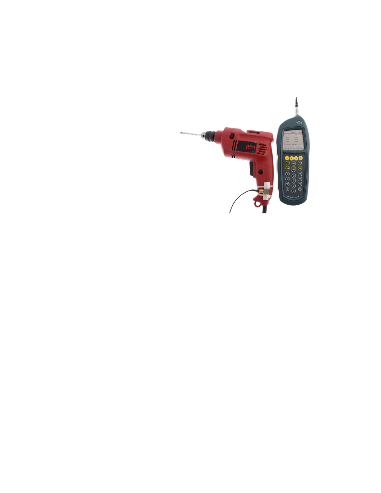
Vexo H - (GA2006H)
Hand Arm Tri-Axial Vibration Meter
&
O
perating Manual
Page 2

Vexo H
HARM Vibration Meter Operating Manual
Published by Castle Group Ltd
Castle Group Ltd
Salter Road
Scarborough
North Yorkshire
YO11 3UZ, UK
Copyright © Castle Group Ltd 2012
All rights reserved. No part of this publication may be reproduced, stored in a
retrieval system or transmitted, in any form or by any means, electronic,
mechanical, photocopying, recording or otherwise, without the prior permission
of the copyright holder.
Printed in the UK
Rev A
HB/2006/009/EL
Page 3

Thank you for buying a Castle product, I am sure you will find both the goods and
the service to be of the highest quality but if not, then please feel free to write to
me personally and I will ensure that your needs are dealt with immediately.
This manual is designed to show you the operation of the goods you have
purchased and a very brief insight into vibration itself. If you would like to become
a competent person in the eyes of the law, then you may like to know more about
our Competent Persons training course for Human Vibration. You can visit
www.castletrainingacademy.com to find out more.
Castle Group has become the leading supplier of solutions for health and safety,
environmental compliance and plant maintenance and monitoring, with an ever
expanding offer comprising equipment for sale or rent, residential or in-house
training courses, consultancy services and equipment calibration. If you would
like to know more about any of our other products and services then please visit
www.castlegroup.co.uk or telephone us on +44(0)1723 584250.
Simon Bull
Managing Director
Note: for ‘Getting Started’ section please turn to Chapter 4
Page 4

Precautions
• Only operate the instrument as described in this manual.
• These are precision instruments, protect from shocks and physical
extremes.
• Ambient conditions for the operation of the unit are as follows:-
Temperature: -10°C to +50°C
Relative Humidity: 25 to 90%
• Protect the unit from extremes of temperature and humidity, direct
sunlight and air with a high salt or sulphur content.
• Always turn the unit off after use.
• Do not use any solvents or cleaning agents on the instrument. Use only a
soft dry cloth or a soft cloth lightly moistened with water when necessary.
• Do not allow any conductive objects, such as wire or metal particles to
enter the unit.
• Do not try to disassemble the instrument or attempt any repairs as this will
invalidate your warranty. Take a note of the condition of the instrument and
contact your authorised Castle service station.
• To ensure continued precision performance of your instrument have it
checked and serviced at regular intervals.
Contacting Castle Group
This manual contains complete operating instructions for the Castle Vexo H
Vibration Meter, read it carefully and you will quickly become familiar with your
instrument and its operation.
If you do encounter problems with the operation of your instrument please feel
free to contact customer support with your enquiry on: -
Telephone: +44 (0)1723 584250
Fax: +44 (0)1723 583728
Website:
www.castlegroup.co.uk
Email: techsupport@castlegroup.co.uk
sales@castlegroup.co.uk
Page 5

Contents
CHAPTER 1 ....................................................................................... 14
Introduction ..................................................................................................................................... 14
Vexo H (GA2006H) – Tri Axial Hand Arm Vibration Meter (HARM) ...... 14
CHAPTER 2 ....................................................................................... 15
Accelerometer Type, Removal and Fitting ....................................................................... 15
Accelerometer Type .............................................................................................................. 15
Vexo H - Hand Arm Tri-Axial Accelerometer (KD1010) ...................................... 15
Attaching & Removing the Accelerometer ................................................................ 16
CHAPTER 3 ....................................................................................... 17
Measuring Vibration ................................................................................................................... 17
Hand Arm Vibration ............................................................................................................... 17
Hand Arm Vibration Transducer Mounting ......................................................... 17
Vibration Direction ............................................................................................................ 18
Vibration Level .................................................................................................................... 19
Frequency Weighting Filter .......................................................................................... 19
Under Range & Overload Conditions....................................................................... 20
Under Range Condition ............................................................................................ 20
Overload Condition ...................................................................................................... 20
CHAPTER 4 ....................................................................................... 21
Getting Started .............................................................................................................................. 21
Keypad Layout .......................................................................................................................... 23
Powering Your Vexo Meter ................................................................................................ 24
Battery Indicator ................................................................................................................ 25
Recharging the Battery Pack ...................................................................................... 26
Switching Your Vexo Meter On/Off ............................................................................... 27
CHAPTER 5 ....................................................................................... 28
Menu Structure ............................................................................................................................. 28
Menu Options............................................................................................................................ 30
Range ...................................................................................................................................... 30
Files .......................................................................................................................................... 31
Open All ............................................................................................................................ 31
Open Today’s ................................................................................................................. 32
Open 7 Days................................................................................................................... 33
Delete Single File .......................................................................................................... 34
Delete All Files ............................................................................................................... 35
Settings .................................................................................................................................. 36
Units ................................................................................................................................... 36
Brightness ...................................................................................................................... 37
Auto Dim .......................................................................................................................... 37
General ............................................................................................................................. 38
Time .............................................................................................................................. 38
Date .............................................................................................................................. 39
File Naming ............................................................................................................... 39
Meter ...................................................................................................................................... 40
Page 6

Reset ................................................................................................................................. 40
Configuration ................................................................................................................. 41
Exposure Points ...................................................................................................... 41
Show Results ........................................................................................................... 42
Information ..................................................................................................................... 42
Calibration ....................................................................................................................... 43
Measurement ......................................................................................................... 43
Sensitivity ................................................................................................................... 46
CHAPTER 6 ....................................................................................... 47
Using the Vexo H .......................................................................................................................... 47
Stop State ................................................................................................................................... 47
Record State ............................................................................................................................. 48
Playback ....................................................................................................................................... 49
Show Results - On ............................................................................................................. 50
Exposure Points - On ........................................................................................................ 51
Under Range Indicator ......................................................................................................... 52
Overload Indicator .................................................................................................................. 53
Parameters ............................................................................................................................... 54
Arms .................................................................................................................................. 54
Aeq ..................................................................................................................................... 54
Amax .................................................................................................................................. 54
Peak ................................................................................................................................... 54
Vector ............................................................................................................................... 54
Exposure .......................................................................................................................... 54
CHAPTER 7 ....................................................................................... 55
Downloading Saved Recordings to a PC ........................................................................... 55
CHAPTER 8 ....................................................................................... 56
Accessories ..................................................................................................................................... 56
CHAPTER 9 ....................................................................................... 57
Technical Specification ............................................................................................................... 57
Applicable Standards ............................................................................................................ 57
Noise Floors ............................................................................................................................... 57
Normal Operating Mode ..................................................................................................... 57
Overload & Under Range Triggering Points .............................................................. 57
Level Ranges ............................................................................................................................. 58
Frequency Weightings ......................................................................................................... 58
Accelerometer ......................................................................................................................... 59
Electrical Signal Input ............................................................................................................ 60
Maximum Electrical Signal Input For No Damage .................................................. 60
Environmental Stabilization Time .................................................................................... 60
Warm up Time ......................................................................................................................... 60
Settling Time ............................................................................................................................. 60
Temperature Operating Range ....................................................................................... 60
Effect of Air Temperature ................................................................................................... 61
Effect of Surface Temperature ........................................................................................ 61
Real Time Clock ....................................................................................................................... 61
Digital Signal Processing ..................................................................................................... 61
Analogue to Digital Converter & Microcontroller ................................................... 61
Displayed Measurement Resolution ............................................................................. 61
Page 7

Display .......................................................................................................................................... 61
Memory ....................................................................................................................................... 62
Overload ....................................................................................................................................... 62
Size and Weight ....................................................................................................................... 62
Connections ............................................................................................................................... 62
AC Output .............................................................................................................................. 62
Wiring Configuration – 4 Pole Jack Socket 3.5mm .................................. 62
Download ............................................................................................................................... 63
Wiring Configuration - Micro USB ‘B’ Socket ................................................ 63
Input Signal ........................................................................................................................... 63
Wiring Configuration – (Lemo Socket EGG.0B.305.CLL) ........................ 63
Battery Recharge ............................................................................................................. 63
Batteries ..................................................................................................................................... 64
EC Declaration of Conformity ............................................................................................ 65
CHAPTER 10 .................................................................................... 66
Function Equations ....................................................................................................................... 66
CHAPTER 11 .................................................................................... 68
Customer Instrument Support .............................................................................................. 68
Warranty and After Sales Service ................................................................................. 68
Disclaimer................................................................................................................................... 70
Instrument Details .................................................................................................................. 70
Table of Figures
Figure 1 - Recommended Axes for Hand Arm Vibration ................................................ 18
Figure 2 - Keypad Layout ................................................................................................................ 23
Page 8

Castle Group Ltd
If you want to keep up to date with the latest in health and safety, you
should attend a Castle FREE seminar. These are run around the country
and cover a wide range of topics. Packed with the latest information and
delivered with the help of practical demonstrations, these seminars are
a great way to really learn something at the same time as collecting cpd
points! Go to the website below to find the lasts dates and venues and to
see video clip samples.
www.need2know4free.com
Dedicated to professionals
in Health and Safety,
Environmental Compliance
and Plant Maintenance
Engineering, Castle set out
to help you in a way that
suits you best. We can
provide or rent equipment,
train you and your staff or
we can carry out work on
your behalf. We can even
mix it up to suit your way of
working.
• Measuring and Monitoring Instruments
• Equipment Rental
• Database and Data-management Software
• Training Courses and In-house Provision
• Calibration and Repair of Monitoring Equipment
• Consultancy for Health, Safety, Environment and Engineering
Solutions
• Online Knowledge
www.castlegroup.co.uk
Page 9

HEALTH AND SAFETY
Compliance with legislation and mitigation of claims is really what health
and safety is about for most companies. That is how we are set up to
help you; Our training courses are all geared to that end as is any
equipment we might supply or rent to you. If you need us in person, we’ll
be there too! Call NOW on 01723 584250 and get your health and
safety compliance on-track, the way you want to do it! There are many
issues you might like us to have a look at
• Noise and Vibration at Work
• Audiometry
• HAVS Health Surveillance
• Health Screening
• Air Sampling and Gas Detection
• Indoor Air Quality
• Airflow
• EMF Testing and Monitoring
• Portable Appliance Testing (PAT)
• General Compliance and Risk
Assessment
ENVIRONMENTAL COMPLIANCE
In an increasingly sensitive atmosphere to environmental issues,
businesses have to be careful. Neighbours are increasingly aware of
theirs ‘right’ to complain and the environmental agencies are looking for
industry to clean up its act. Simply call us on 01723 584250 if you
have any environmental compliance issues and we will work with you to
find the best way forward.
• Noise for Planning
• Complaint Management
• Ground-Bourne & Building Vibration
• Stack-Emissions Monitoring
• Environmental Air Sampling
• Water Quality Testing
Page 10
MAINTENANCE AND DIAGNOSTICS
Production plant needs maintenance and if this can be done only when
needed, then cost savings can be huge. Condition monitoring offers the
ability carry out predictive maintenance so shut-down is only when you
plan it and only when it’s needed. It is very simple to work out if this is the
right approach for your business, so give us a call on 01723 584250
so we find out how much you could save!
• Vibration Monitoring Systems
• Vibration Meters
• Temperature Monitoring System
• Thermometers
• Thermal Imaging
• Diagnostic Vibration Analysis
• Tachometers
• Inspection Endoscopes
Services
Castle Training Academy
Competence and Compliance training is essentially all about obtaining
the knowledge and skills required to get the job done. This is precisely
how Castle courses are set out, with a high degree of practical ‘handson’ experience mixed with some background theory and a lot of jobspecific information and discussion. If this doesn’t whet the appetite,
then there is also a fully inclusive dinner on the first nigh – perfect for
getting to know some of your peers! You can see a full list of courses on
our website.
• Health and Safety Compliance Courses
Noise, Vibration, COSHH, Asbestos
• Health Surveillance Courses
Audiometry, Lung Function, HAVS
• Environmental Monitoring Courses
Noise, Vibration, Air Quality
• Diagnostic Engineering Courses
• Maintenance and Monitoring Courses
Page 11

In-house and Bespoke Training
The benefits of in-house training can be extensive. Training can be
tailored to your company, the timing can be made to suit your needs, you
get to keep your staff on-site and you can train many people at one go!
You can pick any of our standard courses, a shortened version as an
awareness session or a toolbox talk, or you can design your own course
covering a large range of topics. Visit our website for a list of ideas!
Castle Consultancy
Sometimes, the comfort of using an independent expert can be
extremely valuable, whether that be for short-term help, Engineering
project work, or an on-going support contract. Castle consultants are
always at the top of their game and are waiting to hear from you. Have a
look at our website or call on 01723 584250.
• Noise and Vibration, COSHH
Assessments
• Light, Temperature, EMF
Assessments
• Environmental Monitoring
• Expert Witness
• Diagnostic Engineering
• Engineering Control Solutions
• Risk Management
• Health Surveillance Services
• Health and Safety ‘Department’
Support Service
Castle Care
Maintaining calibrations on measuring equipment is absolutely essential
to the integrity of your data. At Castle, we can calibrate virtually anything
you have that can measure. We pride ourselves in fast-as-possible
turnaround times and can normally give up-front prices for almost any
equipment. Whether you have an anemometer, or a ‘zero-g‘
accelerometer, then call us for a price on 01723 584250.
• If it Measures, and can be done - we’ll Calibrate it
• UKAS Certificates Available
• Multiple levels of Calibration
Page 12
Equipment Types Covered
• Air quality meters
• Air sampling pumps
• Air sampling calibrators
• Anemometers
• Audiometers
• Balances/Scales
• Barometers
• Dosemeters
• Electrical test equipment
• Force meters
• Gas Detectors
• Hygrometers
• Light meters
• Manometers
• Moisture meters
• Noise meters
• Pressure meters
• Sound level meters
• Sound analysers
• Strain gauges
• Tachometers
• Thermometers
• Thermo-hygrometers
• Thickness meters
• Timers
• Vibration meters
• Vibration analysers
• Weighing equipment
Castle Contract
If peace of mind for equipment calibrations is important to you – and it
should be, then check out our contract calibration deals. We will give you
discounted, fixed-annual-pricing for selections of equipment and we will
undertake to ensure calibration is maintained to your schedule. This is
designed to take all the hassle out of equipment calibration.
• Maintain Instrument Calibrations
• Hassle-Free Administration
• Discounted Calibration Fees
• Single-Source Supplier
Page 13
Castle Rent
Rental is a great way to have the use of measurement equipment
without having to own it – especially is capital budgets are tight or it tax
is an issue. If you need a short term solution, additional equipment to
boost your capabilities or if contract-based tax deduction is important,
then Rental could well be the way to go. Go to our website to find the
huge range of equipment we have available.
You might also like to make use of our ex-rental purchase as a way of
keeping your equipment costs down.
• Easy on Cash-Flow
• Short or Long Term
Rentals
• Let the Taxman Pay on
Contracts
• Try Before You Buy
• 4 weeks for the Price of 3!
• No On-going Maintenance
If it exists - we’ll even source equipment for you!
www.castlegroup.co.uk
01723 584250
Page 14

Page 14
Chapter 1
Introduction
Vexo H (GA2006H) – Tri Axial Hand Arm Vibration Meter (HARM)
Thank you for purchasing your product from Castle Group Ltd.
The Vexo H Tri Axial vibration meter brings simplicity, looks, value for money and
power to the world of vibration monitoring.
The instrument is fully compliant with the standard ISO 8041:2005 and has
been designed to make sure workers do not exceed the exposure to vibration
levels as stated by the Control of Vibration at Work Regulations (2005).
It boasts a clear easy to read colour LCD and has full data logging capabilities
with fast USB downloading to your laptop or PC. The Vexo incorporates internal
Flash memory to store all your recordings and the data can then be transferred
to the supplied software Vibdata LITE using the supplied USB cable or viewed
onscreen.
Not only does the Vexo H vibration meter have all these features in a small and
ergonomic case but it is also supplied with a rechargeable battery pack
featuring the latest NiMH technology which incorporates extremely low selfdischarge.
Every part of the Vexo has been thoughtfully designed. The case, accelerometer
and cable are all rugged for industrial use and the meter is extremely easy to
use with a simple three button operation, all you virtually need do is press the
power button and start recording.
With the Vexo H combating HAVS has become even easier.
Page 15
Page 15
Chapter 2
Accelerometer Type, Removal and Fitting
The accelerometer for use with the Vexo H produces a Voltage Output
proportional to the signal being measured.
The table below shows the output voltage and specifications for the
accelerometer where g is the acceleration due to gravity on the Earth’s surface
and is defined as 9.80665 ms
-2
.
Acceleration is measured in metres per second per second (m/s/s) which can
be written as either of the following: -
• ms
-2
• m/s
2
Accelerometer Type
Vexo H - Hand Arm Tri-Axial Accelerometer (KD1010)
Accelerometer
Type
Output
Voltage
Operating
Range
Frequency
Response
Hand Arm 10mV/g ±200g 2 to 5000Hz ±10%
Hand Arm Vibration
Tri-Axial
Accelerometer
(KD1010)
Page 16

Page 16
Attaching & Removing the Accelerometer
On the accelerometer cable connector locate the orientation key, and on the
instrument locate the RED keying identification mark of the 5 pin Lemo socket.
Position the accelerometer cable so that the orientation key is in line with the
RED mark and then gently push the accelerometer cable into the instruments
socket.
To unlatch and remove the accelerometer cable gently pull the on the knurled
part of the stem and pull the accelerometer from the instrument.
Do not twist the connector, doing so will likely damage internal wiring which
would not be covered under warranty.
Removal of the accelerometer can be achieved with the instrument powered on
or off.
Page 17

Page 17
Chapter 3
Measuring Vibration
Hand Arm Vibration
It is advisable to validate your instrument prior to, and after taking
measurements using a known vibration source such as the Castle GA606
Vibration Calibrator.
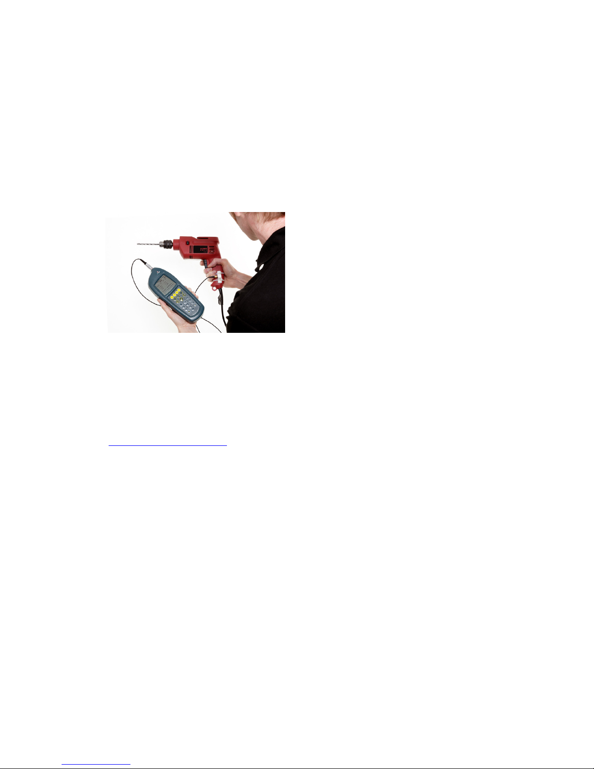
To ensure measurements are as accurate and as repeatable as possible always
ensure that your cable is tightened securely to your accelerometer and that the
accelerometer is mounted as securely and as flush as possible to the vibration
source. The trailing cable of the accelerometer should also be attached to the
vibration source without creating a potential hazard for the operator or other
people.
Where possible always mount the accelerometer as near to the centre of
where the operator holds and grips the vibration source. In reality this is not
always possible and the best compromise must be achieved.
Measurement durations are dependant on the vibration source, and a minimum
period of 30 seconds for Hand Arm Vibration is recommended. Measurement
periods of 3 to 15 minutes are often used for Hand Arm vibration. These
increased durations will undoubtedly increase the accuracy and repeatability of
your measured results.
Hand Arm Vibration Transducer Mounting
The supplied mounting block can be attached to the HARM accelerometer using
the supplied screw and tightened using a Phillips screw driver. The mounting
block can then be mounted to the vibration source using hose clamps or plastic
ties. If plastic ties are used it is recommended that they are tightened using a
tie tensioning tool. Attaching devices such as clamps and the accelerometer to
hand held devices may alter the mass of the vibration source and will inevitably
slightly alter the vibration emitted from the device, it is therefore recommended
to keep the mass of hose clips or clamps to a minimum.
Other mounting possibilities to mount the accelerometer to the vibration source
are tapping a stud into the vibration source and attaching the accelerometer to
the stud. Alternatively the stud may be adhered to the device rather than
tapped with an adhesive that dries rigid. Castle Group Ltd can supply a glue and
stud pack if required, (order code KD1215). See Accessories for more options.
Page 18
Page 18
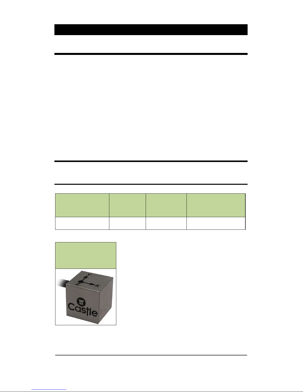
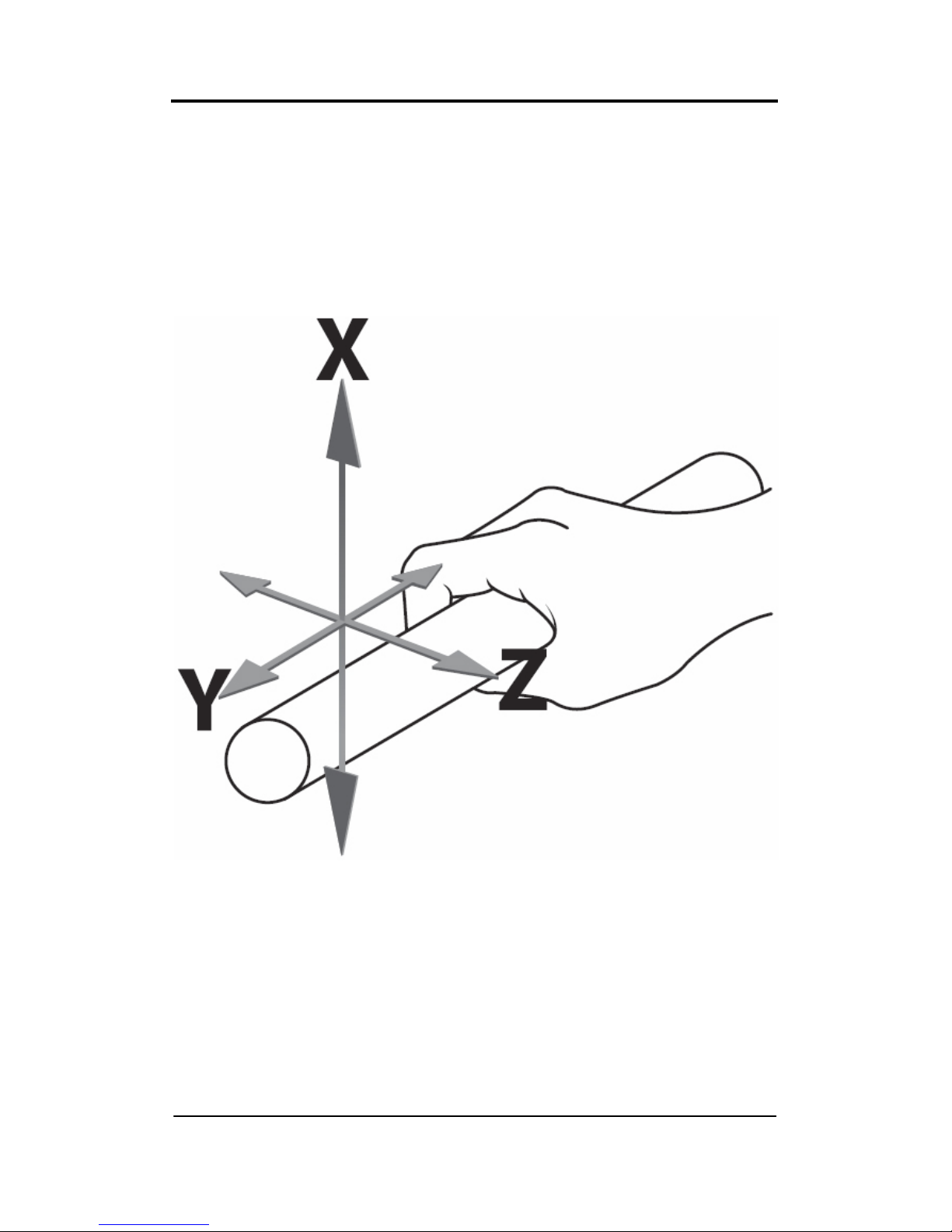
Vibration Direction
For Hand Arm vibration, the three axes being measured can be measured in any
orientation; however it is recommended that the suggested axes indicated in the
figure below are used. If this is not possible, then choosing other axes
orientation is permissible and will not affect your measured data.
In all cases it is strongly recommended to make notes on the axes used relative
to the vibration source. This information will be required if vibration control is to
be implemented on the vibration source.
Figure 1 - Recommended Axes for Hand Arm Vibration
Page 19
Page 19
Vibration Level
In some environments, high levels of vibration may occur. Before you record
measurements take the time to ensure you have selected the optimum range
for the process being recorded.
The optimum range is generally the lowest range that can be selected that does
not produce an overload condition for the process being monitored.
Where high levels of vibration are encountered the meter may register an
overload and in these circumstances the meter will display that this has
occurred. In such cases you will need to select the high range to accommodate
the higher peak levels and if Overload conditions are still occurring on the high
range it may be necessary to use an impact filter on the accelerometer.
If the vibration levels are too low for the range selected then the meter will
display an under range condition. Under these circumstances you will need to
select the low range if possible.
For more detailed information see Under Range & Overload Conditions.
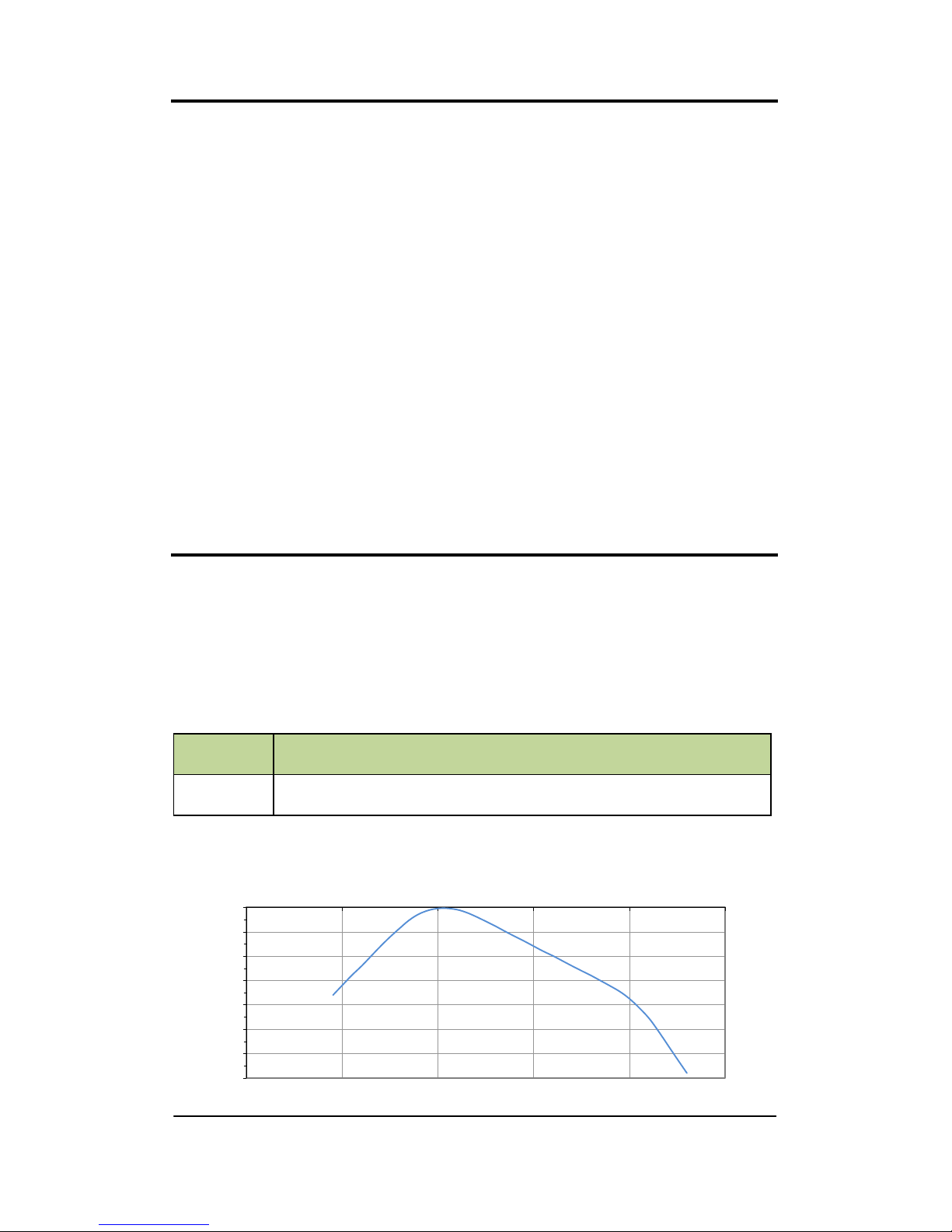
Frequency Weighting Filter
The human body’s discomfort level to vibration alters depending on the vibration
frequency and where the vibration is in contact with the body.
Your Vexo H meter therefore has the following frequency weighting filter which
is applied to the measured vibration signal using a fast processor for superior
accuracy: -
Hand Arm Vibration
Filter Description
Wh
Always used for Hand Arm Vibration measurement in the X, Y
and Z Axis.
Wh Filter Frequency Response:
-70
-60
-50
-40
-30
-20
-10
0
0.10 1.00 10.00 100.00 1000.00 10000.00
Gain (dB)
Frequency (Hz)
Page 20

Page 20
Under Range & Overload Conditions
Under Range Condition
An under range condition occurs when the vibration level is equal to, or lower
than the bottom of the current range the meter is set to. If this condition
occurs then the UR (Under Range) indicator will be displayed on your
instrument. In such circumstances it is highly recommended to change to a
lower range with a higher sensitivity as your meter will be out of specification.
The under range indicator will remain on for a minimum of 2 seconds or while
the under range condition remains.
Placement of the under range indicator can be found under Under Range
Indicator in Chapter 6.
See Technical Specification for a complete list of Under Range triggering
points.
Overload Condition
An overload condition occurs when either the peak signal starts to exceed the
signal handling capability of the specialised amplifier circuitry or if the vibration
level exceeds the top of the selected range by 5%. If the vibration source
saturates the input circuitry or is 5% greater than top of the selected range an
Overload condition occurs and an OL (Overload) indicator is displayed on your
instrument.
If an overload condition occurs it is highly recommended to change to a higher
range with a lower sensitivity as your meter will be out of specification.
The overload indicator will remain on for a minimum of 2 seconds or while the
overload condition remains.
Please be aware that the selected frequency weighting may attenuate the
displayed signal level below the overload triggering point but an overload can still
occur. This is because the overload operates from the unweighted input signal.
Placement of the overload indicator can be found under Overload Indictor in
Chapter 6.
See Technical Specification for a complete list of Overload triggering points.
Page 21
Page 21
Chapter 4
Getting Started
The Vexo H instrument has three states of basic operation: -
• Stop State
• Record State
• Playback
Whilst the instrument is in the Record State the vibration activity is analysed
and all parameters available on your instrument are calculated.
The data captured is saved to the internal flash memory and can be viewed
onscreen or downloaded to Castle’s vibration analysis software Vibdata LITE or
VibdataPro as and when required.
To Start or Stop a recording press the following key
Whilst the instrument is in the Stop State, calculations are displayed on screen
but are not stored in flash memory.
Exposure Points are only available at the end of a recording or when viewing a
saved recording. The option to display Exposure Points must also be set to On.
During Stop State it is possible to change the Settings and undertake Calibration
of the instrument.
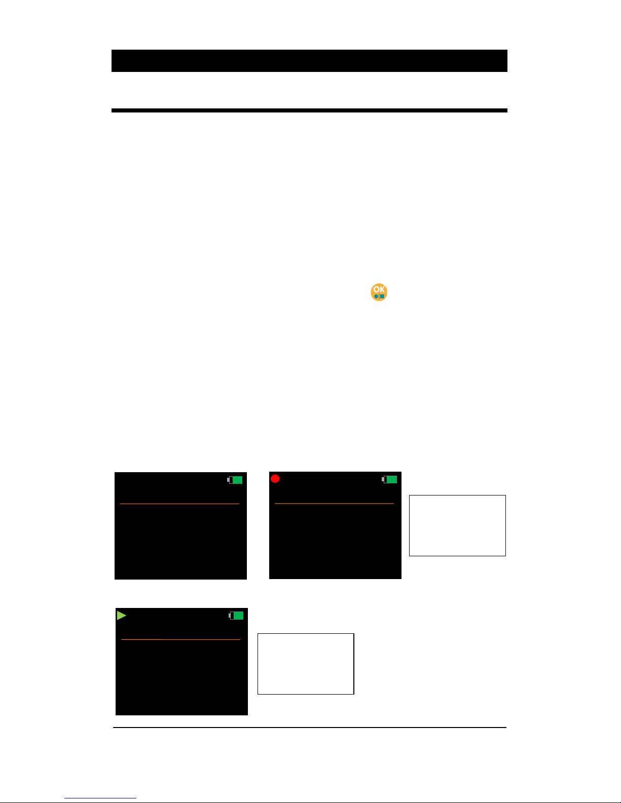
Stop State, Record State and playback can easily be distinguished: -
Record State
shows Record
Symbol and
Time Recorded
A
eq
m/s
2
OL
X: 4.12
m/s
2
OL
Y: 3.25
m/s
2
OL
Z: 4.01
00:02:01
W
h
Playback
Playback shows
Play Symbol
and Total Time
Recorded
W
h
A
rms
m/s
2
OL
X: 3.51
m/s
2
OL
Y: 2.18
m/s
2
OL
Z: 1.04
W
h
A
rms
m/s
2
OL
X: 3.51
m/s
2
OL
Y: 2.18
m/s
2
OL
Z: 1.04
00:00:01
Stop State
Record State
Page 22
Page 22
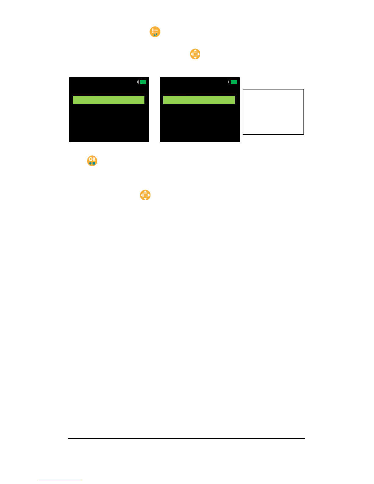
Whilst in Stop State press to open the Main Menu. This key is also used to
step back to the previous screen.
With the Main Menu screen open, use to scroll down the list of available
options: -
Press to select the required option. Note that a recording cannot be started
from within the Main Menu.
Some options may also have further sub-menus where further options are
available. Again use the
key to scroll through the available options.
The menu structure is described in detail in Chapter 5.
Please be aware that your Vexo H instrument has a built in battery saving
function that automatically dims the display. Any key can be pressed to exit this
power saving function. See Auto Dim in Chapter 5 for more details.
If the instrument
has no files
saved then the
Files option is
not selectable
Menu
14:32 23/08/12
Range
Files
Settings
Meter
Menu
14:32 23/08/12
Range
Files
Settings
Meter
Page 23
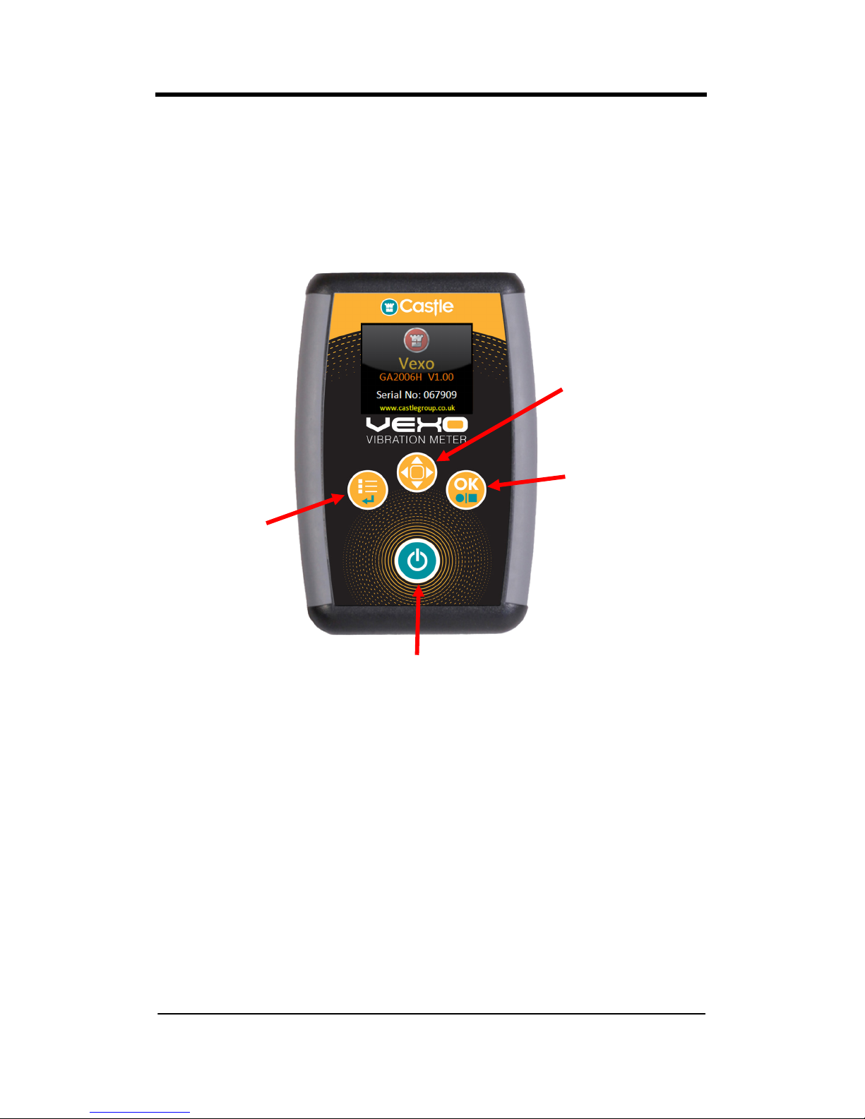
Page 23
Figure 2 – Keypad Layout
Keypad Layout
Please note that some keys have a dual function.
Power On / Off
Record / Stop
Main Menu
Scroll
OK
Back
Page 24

Page 24
Powering Your Vexo Meter
Your Vexo meter is powered from a Castle rechargeable 2.4V NiMH battery
pack. The battery pack employs the latest battery technology for maximum
battery life between instrument uses.
The battery compartment is located on the underside of your instrument. Open
the battery door by sliding the cover downwards towards the bottom of the
instrument.
The cover can now be removed exposing the battery compartment and battery
pack if fitted.
To fit a battery pack, plug the battery pack into the connector and insert the
battery pack at an angle as shown below: -
Page 25

Page 25
Push the raised end of the battery pack downwards as indicated until the
battery pack sits comfortably in place.
Ensure battery cabling does not overlap or obstruct where the battery door is
inserted.
Battery Indicator
Your Vexo meter is equipped with a four stage battery level indicator and is
visible in the top right hand corner of all screens.
With a fully charged battery pack the indicator with a full Green bar is displayed
and as the battery pack discharges the relevant indicator is displayed.
The approximate values are 100%, 75%, 50% and 25%
When the battery pack is below 10% it will flash Red indicating that the battery
pack is flat and requires a recharge.
When the battery pack is below 4% it will automatically power the unit down and
save any data if the instrument is in Record State.
Page 26

Page 26
Recharging the Battery Pack
With a battery pack inserted and your instrument switched off plug your
supplied charging unit into the DC socket indicated below: -
The Vexo instrument will not operate while the battery pack is charging and will
immediately switch off when the charger is plugged in to the DC socket, even if
the charger is not switched on. This is normal.
If the unit switches off due to the charger plug being inserted then no settings or
recordings will be saved.
A completely discharged battery pack may need several hours to become fully
charged.
Observe the LED on the charging unit to determine the charging cycle.
When the charging unit displays a constant Green LED then charging is
complete.
For safety only use the charging unit and battery pack supplied by Castle.
LED Colour Mode Output
Yellow No Battery 6.4V
Yellow Initialisation 30mA
Orange Fast Charge 1.3A
Green/Yellow Top-off Charge 160mA
Green Trickle Charge 30mA
Orange/Green Error 30mA
Page 27

Page 27
Switching Your Vexo Meter On/Off
To turn on your instrument press and hold the Power On/Off key for
approximately two seconds.
Your meter will display the start-up screen and initialise any saved settings.
The start-up screen is shown below: -
Once the start-up sequence is complete the instrument is placed in its Stop
State displaying the parameter measuring screen.
To turn off your instrument press and hold the Power On/Off key for
approximately three seconds and the following screen will be displayed: -
Release the Power On/Off key
to shut down.
Your Vexo meter is also equipped with an automatic shut down if no key is
pressed for 3 minutes after power on.
If any key is pressed after the instrument is turned on then the automatic
shutdown will not occur.
Vexo
GA2006H V1.00
www.castlegroup.co.uk
Serial No: 067909
Shut Down
14:32 23/08/12
Release
Power Key
To Shutdown
Page 28

Page 28
Chapter 5
Menu Structure
Whilst in Stop State press to open the Main Menu. This key is also used to
step back to the previous screen.
With the Main Menu screen open, use to scroll down the list of available
options: -
Press to select the required option. Note that a recording cannot be started
from within the Main Menu.
Some options may also have further sub-menus where further options are
available. Again use the
key to scroll through the available options.
The complete menu structure is shown below: -
If the instrument
has no files
saved then the
Files option is
not selectable
Menu
14:32 23/08/12
Range
Files
Settings
Meter
Menu
14:32 23/08/12
Range
Files
Settings
Meter
Page 29

Page 29
Page 30

Page 30
Menu Options
Each Menu option is described fully below: -
Range
Select this option to change the measuring range of your Vexo instrument.
Use the
key to highlight the required option and press to select. The
range will be selected and the previous menu screen will be displayed.
Range details are as follows: -
Range (m/s2) (g)
High 0.50 – 2000 0.051 – 204
Low 0.05 – 200 0.0051 – 20.4
Press
to return to the previous screen without making a selection.
Red Tick
indicates
current
selection
Range
14:32 23/08/12
High
Low
Page 31

Page 31
Open
14:32 23/08/12
10:25:30
11:36:30
11:23:35
1/3
06/08/12
05/08/12
05/08/12
Files
Select this option to manage saved recordings on your Vexo instrument.
Use the key to highlight the required option and press to select.
Press
to return to the previous screen without making a selection.
Open All
Select this option to show all saved recordings on the instrument. Recordings
are listed by file name, date and time order showing the most recent first.
The file number and amount of recorded files are also shown in Red: -
Use the
key to highlight the required file and press to open it.
If more than 5 files exist then use the
key to scroll through the available
recordings: -
Press
to return to the previous screen without making a selection.
If no files have
been recorded
today or in the
last 7 days
then these
options will not
be selectable
Files
14:32 23/08/12
Open All
Open Today’s
Open 7 Days
Delete Single File
Delete All Files
Files
14:32 23/08/12
Open All
Open Today’s
Open 7 Days
Delete Single File
Delete All Files
Open
14:32 23/08/12
12:13:03
16:55:00
16:33:45
15:15:30
13:26:35
126/144
09/08/12
08/08/12
08/08/12
08/08/12
08/08/12
Page 32

Page 32
Open
14:32 23/08/12
09:35:20
09:22:25
09:12:12
1/3
23/08/12
23/08/12
23/08/12
Open Today’s
Select this option to show all saved recordings made today on the instrument.
The recordings are listed by file name, date and time order showing the most
recent first.
Note that this option is not selectable if no recordings have been made today.
The file number and amount of recorded files are also shown in Red: -
Use the
key to highlight the required file and press to open it.
If more than 5 files exist then use the
key to scroll through the available
recordings: -
Press
to return to the previous screen without making a selection.
Open
16:32 23/08/12
10:55:00
10:33:45
10:15:30
09:56:35
09:43:03
6/23
23/08/12
23/08/12
23/08/12
23/08/12
23/08/12
Page 33

Page 33
Open
14:32 23/08/12
09:12:12
09:35:20
09:22:25
1/3
20/08/12
17/08/12
17/08/12
Open 7 Days
Select this option to show all saved recordings made in the last 7 days.
The recordings are listed by file name, date and time order showing the most
recent first.
Note that this option is not selectable if no recordings have been made in the
last 7 days.
The file number and amount of recorded files are also shown in Red: -
Use the
key to highlight the required file and press to open it.
If more than 5 files exist then use the
key to scroll through the available
recordings: -
Press
to return to the previous screen without making a selection.
Open
16:32 23/08/12
10:55:00
10:33:45
10:15:30
09:56:35
09:43:03
6/23
20/08/12
20/08/12
20/08/12
20/08/12
20/08/12
Page 34

Page 34
Delete
14:32 23/08/12
09:12:12
09:35:20
09:22:25
1/3
20/08/12
17/08/12
17/08/12
Delete
14:32 23/08/12
09:35:20
09:22:25
1/2
20/08/12
17/08/12
Delete Single File
Select this option to delete an individual file from the instruments flash memory.
Deleted files cannot be recovered.
The recordings on the instrument are listed by file name, date and time order
showing the most recent first.
All recordings will be available for selection and the file number and amount of
recorded files are shown in Red: -
Use the
key to highlight the required file and press to delete it.
The selected file will be immediately deleted: -
If more than 5 files exist then use the
key to scroll through the available
recordings: -
Press
to return to the previous screen without making a selection.
Open
16:32 23/08/12
10:55:00
10:33:45
10:15:30
09:56:35
09:43:03
6/23
20/08/12
20/08/12
20/08/12
20/08/12
20/08/12
Page 35

Page 35
Delete
14:32 23/08/12
No
Yes
Delete All
Delete All
Delete All Files
Select this option to delete all recordings from the instruments flash memory.
Proceed with caution as deleted files cannot be recovered: -
Use the
key to highlight the required option and press to proceed.
Select No or press
to return to the previous screen without deleting any
files.
Select Yes to delete all saved files. Delete All Files will be highlighted red: -
When all files are deleted the Main Menu is displayed: -
Files
14:32 23/08/12
Open All
Open Today’s
Open 7 Days
Delete Single File
Delete All Files
Menu
14:32
Range
Files
Settings
Meter
Page 36

Page 36
Settings
Select this option to manage settings on your Vexo instrument.
Use the key to highlight the required option and press to select.
Press
to return to the previous screen without making a selection.
Units
Select this option to change the units of measure of your Vexo instrument.
Use the
key to highlight the required option and press to select. The
unit will be selected and the previous menu screen will be displayed.
Press
to return to the previous screen without making a selection.
Current
selections
are shown
at the right
hand side
Settings
14:32 23/08/12
Units
Brightness
Auto Dim
General
S
Met
60%
OnG
S
Red Tick
indicates
current
selection
Units
14:32 23/08/12
Metric
g
Page 37

Page 37
Brightness
Select this option to change the display brightness of your Vexo instrument.
Use the
key to change the brightness level and the press to return to
the previous screen with the selected brightness level.
The display brightness can be adjusted between 20% and 100% in 20% steps.
Press
to return to the previous screen without altering the brightness level.
Note that the brightness may be affected by the Auto Dim function - see below.
Auto Dim
Select this option to determine if your Vexo instrument should use the Auto Dim
function or not.
The Auto Dim function is a battery saving feature that automatically reduces the
display brightness of all screens to 10% if no key has been pressed for 30
seconds.
For optimum battery life, the Auto Dim should be switched On.
Use the
key to highlight the required option and press to select. The
option will be selected and the previous menu screen will be displayed.
Press to return to the previous screen without making a selection.
Whilst the Auto Dim feature is active press any key to deactivate it and return to
the selected brightness level.
Brightness
14:32 23/08/12
60%
Red Tick
indicates
current
selection
Auto Dim
14:32 23/08/12
Off
On
Page 38

Page 38
General
Select this option to open another menu level of General options.
Use the
key to highlight the required option and press to select.
Press
to return to the previous screen without making a selection.
Time
Select this option to change the time stored on your Vexo instrument.
Use the
key to change the value highlighted then press to move the
highlight to the next position.
If an invalid time is selected the warning message Invalid Time will be displayed
in red.
Press to return to the previous screen with any valid changes made.
General
14:32 23/08/12
Time
Date
File Naming
Time
14:32 23/08/12
1 4:32: 15
Time
14:32 23/08/12
2 4:32: 15
Invalid Time
Invalid
Time
warning
Message
Page 39

Page 39
Date
Select this option to change the date stored on your Vexo instrument.
Use the
key to change the value highlighted then press to move the
highlight to the next position. If an invalid date is selected the warning message
Invalid Date will be displayed in red.
Press to return to the previous screen with any valid changes made.
File Naming
Select this option to determine if your Vexo instrument should store File Names
with saved recordings or not.
A file name must be entered when ending a recording if this option is turned on.
Use the key to highlight the required option and press to select. The
option will be selected and the previous menu screen will be displayed.
Press to return to the previous screen without making a selection.
Date
14:32 23/08/12
2 3:08: 12
Date
14:32 23/08/12
3 3:08: 12
Invalid Date
Invalid
Date
warning
Message
Red Tick
indicates
current
selection
File Naming
14:32 23/08/12
Off
On
Page 40

Page 40
Meter
Select this option to change operational configuration settings, calibrate your
instrument and view system information.
Use the key to highlight the required option and press to select.
Press
to return to the previous screen without making a selection.
Reset
Select this option to reset all measurement parameter values.
The highlight turns red for 3 seconds to indicate that a reset has been
performed.
Meter
14:32 23/08/12
Reset
Configuration
Information
Calibration
S
Meter
14:32 23/08/12
Reset
Configuration
Information
Calibration
S
Page 41

Page 41
Configuration
Select this option to change operational configuration settings.
Use the key to highlight the required option and press to select.
Press
to return to the previous screen without making a selection.
Exposure Points
Select this option to determine if your Vexo H instrument should display
exposure points after ending a recording.
Use the
key to highlight the required option and press to select.
Press
to return to the previous screen without making a selection.
Exposure points were developed in the UK by the Health and Safety Executive
such that combinations of vibration magnitude and exposure time are given in
Exposure Points rather than in values in m/s
2
.
Exposure points may be easier to work with as they can simply be added
together.
Configuration
14:32 23/08/12
Exposure Points
Show Results
S
Red Tick
indicates
current
selection
Exposure
14:32 23/08/12
Points Off
Points On
Page 42

Page 42
Show Results
Select this option to determine if your Vexo instrument should display calculated
results after ending a recording.
Use the
key to highlight the required option and press to select.
Press
to return to the previous screen without making a selection.
Information
Select this option for instrument details.
Red Tick
indicates
current
selection
Show Results
14:32 23/08/12
Off
On
Information
14:32 23/08/12
Vexo
Model GA2006H
Version 1.09
S/N: 069000
Free Memory 100%
Page 43

Page 43
Calibration
Select this option to calibrate your Vexo instrument using accelerometer
sensitivity figures or using a calibrator.
Use the key to highlight the required option and press to select.
Press
to return to the previous screen without making a selection.
Measurement
Select this option to choose between calibrating your Vexo instrument using a
calibrator and selecting the output level of the calibrator.
Use the key to highlight the required option and press to select.
Press
to return to the previous screen without making a selection.
Calibration
14:32 23/08/12
Measurement
Sensitivity
S
Measurement
14:32 23/08/12
Calibrate
Value
S
10.00m/s2
S
Page 44

Page 44
X:
Y:
Z:
10.00
0.004
0.005
Cal Value = 10.00 m/s
2
Axis Calibrated
m/s2
m/s2
m/s2
Calibrate
Select this option to calibrate your Vexo instrument using a calibrator.
Attach the accelerometer to the calibrator such that the vibration travels
through your chosen Axis.
Use the
key to highlight the relevant axis and press to select ensuring
your calibrator is also switched on.
Calibration of each axis takes 15 seconds to complete.
If calibration is successful Axis Calibrated will be shown in Yellow for 5 seconds
or if the calibration fails Calibration Failed will be displayed in Red for 5 seconds.
Press
to return to the previous screen.
Calibrate
14:32 23/08/12
X:
Y:
Z:
10.05
0.004
0.005
Cal Value = 10.00 m/s
2
OK to Calibrate
m/s2
m/s2
m/s2
Calibrate
14:32 23/08/12
X:
Y:
Z:
10.02
0.004
0.005
Cal Value = 10.00 m/s
2
Calibrating Axis
m/s2
m/s2
m/s2
Calibrate
14:32 23/08/12
X:
Y:
Z:
0.005
0.004
0.005
Cal Value = 10.00 m/s
2
Calibration Failed
m/s2
m/s2
m/s2
Calibrate
14:32 23/08/12
Page 45

Page 45
Value
Select this option to change the value that your vibration calibrator outputs in
m/s
2
.
Use the
key to change the value highlighted then press to move the
highlight to the next position.
Valid levels are between 9.00 and 11.00 m/s
2
.
If an invalid value is selected the warning message Value Not Valid will be
displayed in red.
Press
to return to the previous screen with any valid changes made.
Value Not
Valid
warning
Message
Value
14:32 23/08/12
m/s2
1 0:00
Calibration Value:
Value
14:32 23/08/12
m/s2
2 0:00
Calibration Value:
Value Not Valid
Page 46

Page 46
Sensitivity
Select this option to set the sensitivity value for each axis that has been supplied
with your accelerometer.
No vibration calibrator is required for this option.
Press
to return to the previous screen with any valid changes made.
Use the key to highlight the relevant axis and press to select and change
its value.
Use the
key to change the value highlighted then press to move the
highlight to the next position.
Valid levels are between 5.00 and 15.00 mV/g.
If an invalid value is selected the warning message 05.00 to 15.00 only will be
displayed in red.
Press to return to the previous screen cancelling any changes made.
Repeat for all axes as required.
Value
14:32 23/08/12
X Value
Y Value
Z Value
10.00
10.00
10.00
mV/g
mV/g
mV/g
Sensitivity
14:32 23/08/12
X Sensitivity Value:
mV/g
1 0:00
Value Not
Valid
warning
Message
Sensitivity
14:32 23/08/12
X Sensitivity Value:
mV/g
2 0:00
05.00 to 15.00 only
Page 47

Page 47
Chapter 6
Using the Vexo H
The Vexo H instrument has three states of basic operation: -
• Stop State
• Record State
• Playback
Stop State
This is the default state of the Vexo H instrument and whilst in this state limited
calculations are displayed on the instruments screen but no values are recorded
in the internal flash memory.
It is only possible to change Settings and undertake Calibration of the instrument
whilst in Stop State. Exposure Points are not available when in Stop State.
Scroll through the available parameters using the
key.
The parameters available in Stop State are: -
• Arms
• Aeq
• Peak
• Vector
Weighting is fixed to Wh (Hand Arm) on the Vexo H instrument, the range can
be changed through the Main Menu.
To start a recording (Record State) press the key at any time.
Parameter
Weighting
Range
Battery Level
Measurements
W
h
A
rms
m/s
2
OL
X: 3.51
m/s
2
OL
Y: 2.18
m/s
2
OL
Z: 1.04
Page 48

Page 48
Record State
Whilst the instrument is in the Record State the vibration activity is analysed
and all parameters available on your instrument are calculated.
Record State is easily identified by the Record Symbol and the Recording Time in
the top left hand corner of the screen.
It is not possible to enter the Menu system or turn the instrument off whilst in
Record State.
Scroll through the available parameters using the
key.
The parameters available in Record State are: -
• Arms
• Aeq
• Peak
• Vector
To end a recording press the
key.
If File Naming is turned on then you will be prompted to enter a file name. See
page 39 for more information.
The data is saved to the internal flash memory. If Show Results or Exposure
Points are turned on, then the instrument will automatically display the relevant
parameters.
If neither of the above are turned on then the instrument is placed back into
Stop State.
Recordings saved on your instrument will not be lost if the battery pack is
removed.
Parameter
Weighting
Range
Battery Level
Measurements
W
h
A
rms
m/s
2
OL
X: 3.51
m/s
2
OL
Y: 2.18
m/s
2
OL
Z: 1.04
00:02:01
Record Symbol &
Recording Time
Page 49

Page 49
Playback
Playback is identified by having a green play symbol in the top left hand corner
and is where a recorded file is opened to be viewed on screen.
When Playback is started manually, all parameters are available to view
including Exposure Points, even if Exposure Points are turned off.
Scroll through the available parameters using the
key.
The parameters / screens available whilst in Playback Mode are: -
• File Details
• Arms
• Aeq
• Peak
• Vector
• Exposure
Exit Playback by pressing either
or and the instrument is placed into
Stop State.
Play Symbol &
Recording Time
File Name (if Entered)
File Start and End
Time/Date
HARM
File:
Start:
End:
00:02:01
Sample01
14:30 23/08/12
14:32 23/08/12
File Details
W
h
Page 50

Page 50
Show Results - On
When a recording is stopped and the option Show Results is turned on then the
instrument will automatically enter Playback and display the recorded
parameters.
Playback is identified by having a green play symbol in the top left hand corner.
Scroll through the available parameters using the
key.
The parameters / screens available whilst in Playback Mode are: -
• File Details
• Arms
• Aeq
• Peak
• Vector
• Exposure
Exit Playback by pressing either
or and the instrument is placed into
Stop State.
HARM
File:
Start:
End:
00:02:01
Sample01
14:30 23/08/12
14:32 23/08/12
File Details
W
h
Only Available if Exposure Points are On
Play Symbol &
Recording Time
File Name (if Entered)
File Start and End
Time/Date
Page 51

Page 51
15m:
30m:
1hr:
51
204
408
Exposure Points - On
When a recording is stopped and the option Exposure Points is turned on then
the instrument will automatically enter Playback and display the Exposure Point
values.
See Show Results – On if Show Results are also turned on.
Playback is identified by having a green play symbol in the top left hand corner.
Exposure Points are shown for periods of 15 minutes, 30 minutes and 1 hour.
The values are also colour coded to give instant visual indication and are based
on the following criteria in the UK specified by the HSE: -
Exit Playback by pressing either or and the instrument is placed into
Stop State.
In accordance with the European Union Physical Agents Directive, the Action
Level and upper Limit Level are set as follows: -
Hand Arm
Action Level
2.50 ms
-2
100 Points
Limit Level
5.00 ms
-2
400 Points
Play Symbol &
Recording Time
00:02:01
Exposure
W
h
Less than Action Value
Aware - Action Value Exceeded
Warning - Limit Level Reached
Page 52

Page 52
Under Range Indicator
Each axis on the Vexo H has independent Under Range indicators which are
visible in Stop State or Record State.
Unlike overload, the under range condition is not saved with the recording and is
therefore not available in Playback.
The under range indicator ‘UR’ is placed in red at the far right of each axis
where the condition occurs: -
The under range indicator remains on for a minimum of 2 seconds or whilst the
under range condition remains.
For Vector Sum where cumulative figures are used the location of the under
range indicator is as below. The indicator on this screen identifies that at least
one axis has at some stage gone under range.
Under Range Indicator
W
h
A
rms
m/s
2
OL
Y: 2.18
m/s
2
OL
Z: 1.04
m/s
2
UR
X: 0.47
Under Range Indicator
W
h
Vector
Amax
4.47
Aeq
2.46
m/s
2
m/s
2
UR
Page 53

Page 53
Overload Indicator
Each axis on the Vexo H has independent Overload indicators which are visible in
Stop State, Record State and Playback.
Unlike under range, the overload condition is saved with the recording and is
therefore also available in Playback.
The overload indicator ‘OL’ is placed in red at the far right of each axis where the
condition occurs: -
The overload indicator remains on for a minimum of 2 seconds or whilst the
overload condition remains however during Stop State or Record State the
overload indicator is latched on the following screens: -
• Aeq
• Vector
It is possible to remove the latched overload indicator during Stop State by
selecting Reset under Meter from the Main Menu.
The overload indicator cannot be reset during Record State or Playback.
For Vector Sum where cumulative figures are used and where Exposure Points
are being displayed the location of the overload indicator is as below. The
indicator on this screen identifies that at least one axis has at some stage
overloaded.
Overload Indicator
Overload Indicator
W
h
A
rms
m/s
2
OL
Y: 2.18
m/s
2
OL
Z: 1.04
m/s
2
OL
X: 2001.0
W
h
Vector
Amax
46.47
Aeq
21.46
m/s
2
m/s
2
OL
Page 54

Page 54
Parameters
The parameters that are recorded and displayed on your Vexo H instrument are
as follows: -
Parameters measured as Acceleration are identified as Acceleration with a
preceding ‘A’.
Brief descriptions of each parameter are given below and for full mathematical
descriptions see Chapter 10, Function Equations.
Arms
The Arms is the Wh weighted, running RMS (Root Mean Square) acceleration
value.
Aeq
The Aeq is time averaged and Wh weighted acceleration value.
Amax
The Amax is the maximum Arms level reached.
Peak
Peak is the highest peak level of the Wh weighted instantaneous acceleration.
Vector
This is the Vector Sum calculation from the Aeq and Amax.
Exposure
The vibration exposure point system is based on the UK’s Health & Safety
Executive’s system where vibration magnitude and exposure time are given in
exposure points rather than m/s2.
Only available by downloading files
Page 55

Page 55
Chapter 7
Downloading Saved Recordings to a PC
Using the supplied software VibdataLITE or VibdataPro (available separately) it is
possible to download the stored recordings on your meter to your PC allowing
the data to be viewed and printed in professional reports.
Communication between a PC and your Vexo meter is made via the USB
connector at the top of your instrument. The correct Castle Vexo USB driver will
need to be installed on your PC, and is automatically installed whilst installing
VibdataLITE.
To ensure data does not become corrupt please ensure that Stop State is
selected on the instrument before downloading saved recordings.
1. Ensure the Vexo instrument is OFF
2. Connect the Vexo instrument to the PC via the USB lead
3. Switch the Vexo instrument ON
Your Vexo instrument is now ready to download data into VibdataPro.
For comprehensive instructions please refer to the VibdataPro user manual.
Page 56

Page 56
Chapter 8
Accessories
GA606 Vibration Calibrator
KA010V* Carry Case for Vexo and Accessories
KD1010* HARM Tri-axial Accelerometer
KD1202 Mounting Studs (Pk 5)
KD1211 Cable Ties Metal Barbed (Pk 100)
KD1215 Transducer Mounting Glue and Stud Pack
KD1217 Transducer Petro wax Mounting Compound
PC009** VibdataPro Vibration Analysis Software
TT4KIT Tensioning Tool and 100 Cable Ties Metal Barbed
01KD1218* Transducer Mounting Block and Screw
01VIBBATT* 2.4V 2100mAh NiMH Battery Pack
01PSU5* NiMH Battery Pack Recharger
01ZL1065-01 AC Output Cable (1 metre)
01ZL1108-01* USB Download Cable (1 metre)
* supplied with the Vexo H
** upgrade from supplied Vibdata LITE
Page 57

Page 57
Chapter 9
Technical Specification
Applicable Standards
ISO 8041:2005 Human Response to Vibration – Measuring Instrumentation
Noise Floors
Axis
Range m/s2 rms
Low High
X 0.002 0.02
Y 0.002 0.02
Z 0.002 0.02
Normal Operating Mode
Fitted with Hand Arm accelerometer KD1010
Overload & Under Range Triggering Points
Points when calibrated with an accelerometer of sensitivity 10.0mV/g
Acceleration : Metric m/s
2
RANGE UR OL
LOW 0.050 200.0
HIGH 0.500 2000.0
Acceleration : g
RANGE UR OL
LOW 0.0051 20.40
HIGH 0.0510 204.0
Page 58

Page 58
Level Ranges
Acceleration : Metric
Acceleration : g
LOW
0.05 – 200 m/s
2
LOW 0.0051 – 20.4g
HIGH
0.50 – 2000 m/s
2
HIGH 0.051 – 204g
Frequency Weightings
Wh weighting as defined in ISO 8041:2005.
Wh Filter Frequency Response: -
-70
-60
-50
-40
-30
-20
-10
0
0.10 1.00 10.00
100.00 1000.00
10000.00
Gain (dB)
Frequency (Hz)
Deviations re 80Hz in dB and tolerances required for a typical Vexo H
instrument: -
Frequency
(Hz)
Wh Tolerance
1 0.2 +2, -∞
2 0.2 +2, -∞
4 0.2 +2, -∞
8 0.1 ±2
12.5 0.0 ±1
20 0.0 ±1
40 0.0 ±1
80 REF ±1
160 0.0 ±1
315 0.0 ±1
630 -0.1 ±1
1000 -0.2 ±2
2000 -1.3 +2, -∞
4000 -6.1 +2, -∞
Page 59

Page 59
Accelerometer
Specification
KD1010
Output Voltage
10mV/g
±20%
Operating Range
±200g
Frequency Response
0.3 to 10000 Hz
±3dB
Resonant Frequency
>30kHz
Weight
30 Grams
Operating Temperature Range
-54°C to 85°C
-65°F to 185°F
Thermal Sensitivity Coefficient
0.18% / °C
0.10% / °F
Linearity
±1%
Electrical Noise Floor
0.003g pk
Transverse Sensitivity
5%
Maximum Shock
7000g pk
Page 60

Page 60
Electrical Signal Input
Electrical signals at frequencies >2Hz can be applied to the Vexo H instruments
by interfacing a suitable signal generator with an output impedance of 600Ω to
the 5 pin Input Lemo Socket, type (EGG.0B.305.CLL).
Each individual axis shall be subject to the following circuitry, (see Signal Wiring).
AGND
SIGNAL
AGND
SIGNAL
+5V
R1
3K3
C1
1000uF
R2
3K3
SIGNAL
GENERATOR
TRANSDUCER
INPUT SOCKET
Maximum Electrical Signal Input For No Damage
5 Volts (Peak to Peak)
Environmental Stabilization Time
30 minutes
Warm up Time
≤ 2 minutes
Settling Time
It is recommended that a calculation settling period of ≥30 seconds is allowed
for in any recording.
Temperature Operating Range
-10°C to +50°C
(Pin 1)
Page 61

Page 61
Effect of Air Temperature
Accuracy better than ±5% over the range -10°C to +50°C
Effect of Surface Temperature
Accuracy better than ±4% over the range -10°C to +50°C
Real Time Clock
Day, Month, Year, Hour, Minute and Seconds at ±2ppm accuracy per day
Digital Signal Processing
Direct processing using digital recursive filters (infinite impulse response)
Analogue to Digital Converter & Microcontroller
ADC: Word Length: 24 bits, Sampling Rate: 16kHz
Processor Operating Frequency: 25MHz (max.)
Displayed Measurement Resolution
High range – 0.01 m/s² up to 99.99, 0.1 m/s² 100.0 – 2000.0 m/s²
Low range – 0.001 m/s² up to 9.999, 0.01 m/s² 10.00 – 200.00 m/s²
Display
OLED Module (160x128 pixels) with 262,144 colours
Refresh Rate ≤ 500mS
Displayed parameter at each update interval is the value at the time of the
update interval.
Page 62

Page 62
Memory
2Mb On-board FLASH allowing up to 992 recordings to be saved.
Overload
Positive overload warning when the input circuit saturates. See
Overload &
Under Range Triggering Points
for overload triggering points.
Size and Weight
Dimensions: (H):117mm (without Cable) x (W) :78mm x (D): 24mm
Weight: 182g approximately (including batteries)
Connections
AC Output
Unweighted
Short circuit Protected
Load Impedance >10k recommended
AC Output Voltages
Range Output Voltage rms at full scale ±1.5dB
LOW 1000mV
HIGH 1000mV
Wiring Configuration – 4 Pole Jack Socket 3.5mm
AC Output
Pin Number
Description
1 Analogue Ground
2 X Axis Output
3 Y Axis Output
4 Z Axis Output
1 4 3
2
Page 63

Page 63
Download
USB 1.0 or 2.0 compatible.
Wiring Configuration - Micro USB ‘B’ Socket
Download
Pin Number Description
1 Vcc
2 D-
3 D+
4 Not Connected
5 Ground
Input Signal
Voltage Mode, 3-Channel Input
Wiring Configuration – (Lemo Socket EGG.0B.305.CLL)
Mating Lemo
Plug FGG.0B.305.CLAD52Z
Transducer Input Socket
Pin Number Description
1 +5V
2 Analogue Ground
3 X Axis Input
4 Y Axis Input
5 Z Axis Input
Battery Recharge
Powered from a nominal AC supply using Mascot 2116, 2 cell battery charger
Centre Terminal: 0V
Outer Terminal: +V
External View
5
1
4
3
2
2
4
3
5
1
Page 64

Page 64
Batteries
Real Time Clock: CR1220 Lithium Battery (Factory Fitted)
Life Expectancy: Approximately 2 years
Main: 2100mAh NiMH Battery Pack
Life Expectancy: 10 hours continuous use (approx.)
Min Battery Level: 1.8V DC
Page 65

Page 65
EC Declaration of Conformity
The CE marking of the Castle Vexo Vibration Meter indicates compliance with the
EMC and Low Voltage Directive.
The C-Tick marking of the Castle Vexo Vibration Meter indicates compliance with
EMC requirements for Australia and New Zealand.
We, Castle Group Ltd declare that the: -
•
Vexo H and Vexo S range of Vibration Meters
have in accordance with the following Electromagnetic Compatibility Directives: -
•
SI 2005/281
•
2004/108/EC
been designed and manufactured to meet the following tests: -
•
EMC Emissions: EC 61000-6-3:2007+A1:2011
EN61326-1:2006
CISPR 22:2008
EN55022:2006+A1:2007
FCC Rules, Part 15 2003 Class B
•
EMC Immunity: IEC 61000-6-2:2005
EN61326-1:2006
Levels: ±4kV(Contact) , ±8kV(Air)
•
RF EM Amplitude Mod: IEC 61000-6-2:2005
Level 10 V/m
No performance or function degradation is noticeable whilst subject to electrostatic discharge or a.c power
frequency and radio frequency fields under any operating condition with the meter and no differences in radio
frequency emissions are apparent between operating modes where appropriate.
Approved cables for use with Castle Vexo meters to comply with these specifications: -
Cable Order Code Length
Vexo to PC (USB) 01ZL1108-01 1m
The technical file for the above is maintained at Castle Headquarters.
I hereby declare that the instruments named above have been designed to comply with the relevant sections of the
above referenced specifications, and that the above named instruments comply with all essential requirements of
the specified Directives.
Simon Bull
Managing Director
Castle Group Ltd, Salter Road, Scarborough, North Yorkshire, YO11 3UZ
August 2012
Page 66

Page 66
Chapter 10
Function Equations
The following table describes mathematically how the functions available on the
Vexo Vibration Meter are calculated. All calculations displayed are subject to
rounding and/or truncation.
Function Equation
Acceleration
(Metric)
Aeq
1
T
0
T
ta( )a
w
( )
2
ta( )⋅
⌠
⌡
d⋅
:= ms
2−
( )
T = total integration time (seconds)
a
w(ta) = instantaneous acceleration value
(ta) = time (seconds)
Acceleration
(g)
Aeq
1
9.807
1
T
0
T
ta( )a
w
( )
2
ta( )⋅
⌠
⌡
d⋅
⋅:= g( )
T = total integration time (seconds)
a
w(ta) = instantaneous acceleration value
(ta) = time (seconds)
Running rms
Acceleration
(Metric)
Arms
1
θ
t θ−
t
ta( )a
w
( )
2
ta( )
⌠
⌡
d⋅:= ms
2−
(
)
t = instantaneous time (seconds)
θ = integration time of the measurement (1 second)
aw(ta) = instantaneous acceleration value
(ta) = time (seconds)
Running rms
Acceleration
(g)
Arms
1
9.807
1
θ
t θ−
t
ta( )a
w
( )
2
ta( )
⌠
⌡
d⋅
⋅:= g( )
t = instantaneous time (seconds)
θ = integration time of the measurement (1 second)
aw(ta) = instantaneous acceleration value
(ta) = time (seconds)
Page 67

Page 67
Function Equation
Vector Sum
(HARM)
VSum X( )
2
Y( )
2
+ Z
2
+:=
X = X Axis Aeq
Y = Y Axis Aeq
Z = Z Axis Aeq
Peak
Peak = The peak level of the weighted instantaneous
acceleration over the measurement period
Maximum
rms Level
(Acceleration)
Amax = The maximum Arms level reached over the
measurement period
Points (15m)
Points 15m( )
Aeq
EAV
2
0.25
8
⋅
100⋅:=
Aeq = Acceleration (Metric)
EAV = Exposure Action Value (2.5 m/s2)
Points (30m)
Points 30m( )
Aeq
EAV
2
0.5
8
⋅
100⋅:=
Aeq = Acceleration (Metric)
EAV = Exposure Action Value (2.5 m/s2)
Points (1h)
Points 1h( )
Aeq
EAV
2
1
8
⋅
100⋅:=
Aeq = Acceleration (Metric)
EAV = Exposure Action Value (2.5 m/s2)
Page 68

Page 68
Chapter 11
Customer Instrument Support
Warranty and After Sales Service
Castle Group Ltd design and manufacture precision instruments, which if
treated with reasonable care and attention should provide many years of trouble
free service.
In the unlikely event of a fault occurring with your product during the warranty
period, the instrument should be returned in its original packaging to Castle
Group Ltd or to an authorised agent. Please enclose a clear description of the
fault to ensure your instrument is dealt with as quickly as possible.
Any misuse or unauthorised repairs will invalidate your warranty.
Damage to your product caused by faulty or leaking batteries is not covered by
the warranty.
Details of the warranty cover are available upon request from Castle Group Ltd
or your authorised agent.
All instruments designed and manufactured by Castle Group Ltd adhere to strict
British and International standards. To ensure your instrument remains
compliant with these standards it is highly recommended that your instrument
is returned annually for calibration.
Annual calibration is particularly important for cases in which instrument
readings are to be used in litigation or compliance work.
For warranty or service please return your instrument to: -
The Service Department
Castle Group Ltd
Salter Road
Cayton Low Road Industrial Estate
Scarborough
North Yorkshire
England
YO11 3UZ
Page 69

Page 69
Question Answer
The instrument will not power on.
Recharge or replace the battery
pack.
The Instrument is not responding on
all or individual axis to inputted
vibration levels.
Turn the instrument Off, wait 10
seconds to allow the instrument to
reset and then turn back On.
Check the cable for possible
damage or incorrect attachment
to the transducer or instrument.
The instrument is displaying
unexpected readings in one or more
modes of operation.
Are the sensitivity values entered
correctly?
Ensure the transducer is fitted
securely to the source of vibration.
Ensure cable is securely fastened.
The overload indicator is permanently
on.
Change to a higher range.
The overload indicator comes on
before the top of the range is reached.
The overload indicator will also be
shown if the input amplifier is
saturated. This is possible even if
the displayed vibration reading on
your instrument is below the top of
the selected range because of the
applied frequency weighting filter.
Page 70

Page 70
Disclaimer
Whilst every effort is made to ensure the accuracy and reliability of both the
instrument described and the associated documentation, Castle Group Ltd
makes no representation or warranties as to the completeness or accuracy of
this information.
Castle Group Ltd assumes no responsibility or liability for any injury, loss or
damage incurred as a result of misinterpreted or inaccurate information.
Any documentation supplied with your product is subject to change without
notice.
Instrument Details
For your records and for future correspondence with Castle Group Ltd
regarding your instrument, please complete the following details: -
Instrument
Instrument Serial Number
Transducer Serial Number
Software Version Number
Purchase Date
Page 71

Index
A
Acceleration ............................................................................................. 15
Accelerometer
Fitting ................................................................................................... 16
Removing ............................................................................................. 16
Sensitivity ............................................................................................. 46
Specifications ................................................................................. 15, 59
Type ...................................................................................................... 15
Accessories ............................................................................................... 56
Action Level .............................................................................................. 51
Action Levels
Hand Arm ............................................................................................. 51
Auto Dim .................................................................................................. 37
B
Battery
Indicator ............................................................................................... 25
Pack ...................................................................................................... 64
Recharging............................................................................................ 26
Battery Indicator ...................................................................................... 25
Battery Pack ............................................................................................. 64
Brightness ................................................................................................ 37
C
Calibration ................................................................................................ 43
Calibrate ............................................................................................... 44
Measurement ....................................................................................... 43
Value .................................................................................................... 45
Configuration ........................................................................................... 41
Connections ............................................................................................. 62
Customer Support .................................................................................... 68
D
Date .......................................................................................................... 39
Delete
All Files ................................................................................................. 35
Single File ............................................................................................. 34
Disclaimer ................................................................................................. 70
Download Recordings .............................................................................. 55
Page 72

E
EC Declaration .......................................................................................... 65
Electrical Noise ......................................................................................... 57
Exposure
Action Level .......................................................................................... 51
Limit Level ............................................................................................ 51
Points ............................................................................................. 41, 51
F
File Naming .............................................................................................. 39
Files .......................................................................................................... 31
Playback ............................................................................................... 49
Frequency Weighted Filters ..................................................................... 58
Hand Arm ............................................................................................. 19
Table Data ........................................................................................ 58
Frequency Weightings.............................................................................. 58
Function Equations .................................................................................. 66
G
General ..................................................................................................... 38
Getting Started ......................................................................................... 21
Keypad Layout ...................................................................................... 23
I
Indicator
Overload ............................................................................................... 53
Under Range ........................................................................................ 52
Information .............................................................................................. 42
Input
Electrical Signal .................................................................................... 60
Maximum Electrical Input Level ........................................................... 60
Wiring Configuration ............................................................................ 63
Instrument Details ................................................................................... 70
Introduction ............................................................................................. 14
K
Keypad Layout .......................................................................................... 23
L
Level Ranges ............................................................................................. 58
Limit Level ................................................................................................ 51
Limit Levels
Hand Arm ............................................................................................. 51
Page 73

M
Measuring Ranges .................................................................................... 58
Measuring Vibration ................................................................................ 17
Memory .................................................................................................... 62
Menu
Options ................................................................................................. 30
Files .................................................................................................. 31
Delete All Files .............................................................................. 35
Delete Single File .......................................................................... 34
Open 7 Days ................................................................................. 33
Open All ........................................................................................ 31
Open Today’s ............................................................................... 32
Meter ............................................................................................... 40
Range ............................................................................................... 30
Settings ............................................................................................. 36
Brightness ..................................................................................... 37
General ......................................................................................... 38
Date .......................................................................................... 39
File Naming............................................................................... 39
Time.......................................................................................... 38
Meter
Calibration ................................................................................ 43
Calibrate ............................................................................... 44
Measurement ....................................................................... 43
Configuration ........................................................................... 41
Exposure Points .................................................................... 41
Show Results ........................................................................ 42
Information .............................................................................. 42
Reset ......................................................................................... 40
Units ............................................................................................. 36
Structure .............................................................................................. 28
Menu Options .......................................................................................... 30
Brightness............................................................................................. 37
Calibrate ............................................................................................... 44
Calibration ............................................................................................ 43
Configuration ....................................................................................... 41
Date ...................................................................................................... 39
Exposure Points .................................................................................... 41
File Naming .......................................................................................... 39
Files ...................................................................................................... 31
General ................................................................................................. 38
Information .......................................................................................... 42
Page 74

Measurement ....................................................................................... 43
Meter ................................................................................................... 40
Range ................................................................................................... 30
Reset .................................................................................................... 40
Settings ................................................................................................. 36
Show Results ........................................................................................ 42
Time ..................................................................................................... 38
Units ..................................................................................................... 36
Menu Structure ........................................................................................ 28
Meter ....................................................................................................... 40
N
Noise Floor ............................................................................................... 57
O
On / Off Key
Location ............................................................................................... 23
Using .............................................................................................. 27, 30
Open
7 Days ................................................................................................... 33
All ......................................................................................................... 31
Playback ............................................................................................... 49
Today’s ................................................................................................. 32
Output
Voltage Levels ...................................................................................... 62
Wiring Configuration ............................................................................ 62
Overload .................................................................................. 20, 53, 57, 62
P
Parameters ............................................................................................... 54
Playback ................................................................................................... 49
Power
Battery Pack ......................................................................................... 64
Powering Your Vexo Meter ...................................................................... 24
R
Range ....................................................................................................... 30
Ranges ...................................................................................................... 58
Recharging the Battery Pack .................................................................... 26
Record State ............................................................................................. 48
Reset ........................................................................................................ 40
Page 75

S
Sensitivity ................................................................................................. 46
Settings..................................................................................................... 36
Settling Time ............................................................................................ 60
Show Results ...................................................................................... 42, 50
Stabilization Time ..................................................................................... 60
Standards ................................................................................................. 57
Stop State ................................................................................................. 47
Switching Your Vexo Meter Off ................................................................ 27
Switching Your Vexo Meter On ................................................................ 27
T
Technical Specification ............................................................................. 57
Temperature Operating Range ................................................................ 60
Time ......................................................................................................... 38
Settling ................................................................................................. 60
Stabilization .......................................................................................... 60
Warm Up .............................................................................................. 60
Transducer Mounting
Hand Arm ............................................................................................. 17
Turn Off .................................................................................................... 27
Turn On .................................................................................................... 27
U
Under Range .................................................................................20, 52, 57
Units ......................................................................................................... 36
Using the Vexo H ...................................................................................... 47
V
Velocity .................................................................................................... 15
Vexo USB Drivers ...................................................................................... 55
VibdataLITE .............................................................................................. 55
Vibration
Direction ............................................................................................... 18
Level ..................................................................................................... 19
Measuring ............................................................................................ 17
W
Warm Up Time ......................................................................................... 60
Warranty .................................................................................................. 68
Page 76

 Loading...