

Page 1

www.castlegroup.co.uk
Operating Manual
Pocket Sound Level Meter
GA113
Page 2

Thank you for buying a Castle product, I am sure you will find both the goods and
the service to be of the highest quality but if not, then please feel free to write to
me personally and I will ensure that your needs are dealt with immediately.
This manual is designed to show you the operation of the goods you have
purchased and a very brief insight into acoustics itself. If you would like to
become a competent person in the eyes of the law, then you may like to know
more about our Competent Persons training course for Noise at Work
Reulations. You can visit www.castle-training.com to find out more.
It is my intention for Castle Group Ltd to provide a wide range of technical health
and safety products and Services of the highest standard. If you would like to
know more about any of our other products and services then please telephone
on +44(0)1723 584250 or visit www.castlegroup.co.uk
Simon Bull
Managing Director
Page 3

Copyright
This manual is copyrighted with all rights reserved. Copying in part or in whole is
prohibited without the prior written consent of Castle Group Ltd.
Precautions
• Only operate the instrument as described in this manual.
• These are precision instruments, protect from shocks and vibrations.
• Ambient conditions for the operation of the unit are as follows:-
Temperature: -10°C to +50°C
Relative Humidity: 25 to 90%
• Protect the unit from extremes of temperature and humidity, direct sunlight
and air with a high salt or sulphur content.
• Always turn the unit off after use. Remove the batteries from the instrument
when not in use.
• Do not use any solvents or cleaning agents on the instrument. Use only a
soft dry cloth or a soft cloth lightly moistened with water when necessary.
• Do not allow any conductive objects, such as wire or metal particles to enter
the unit.
• Do not try to disassemble the instrument or attempt any repairs as this will
invalidate your warranty. Take a note of the condition of the instrument and
contact your authorised Castle service station.
• To ensure continued precision performance of your instrument have it
checked and serviced at regular intervals.
Contacting Castle Group
This manual contains complete operating instructions for the Castle Pocket
Sound Level Meter range, read it carefully and you will quickly become familiar
with your instrument and its operation.
If you do encounter problems with the operation of your instrument please feel
free to contact customer support with your enquiry on: -
Telephone: +44 (0)1723 584250
Fax: +44 (0)1723 583728
Website: www.castlegroup.co.uk
Email: techsupport@castlegroup.co.uk
sales@castlegroup.co.uk
Page 4

Contents
Introduction............................................................................................... 1
Using the Manual.................................................................................... 1
Sample Keypad Layout.......................................................................... 2
Operating Tips.......................................................................................... 3
Battery Installation / Check............................................................... 4
Microphone ............................................................................................... 4
Switching the Instrument On & Off.................................................. 5
Information Button................................................................................. 5
Pause / Play Button .............................................................................. 6
Display Button.......................................................................................... 6
Menu Button............................................................................................. 8
Calibration.......................................................................................................................... 8
Shift Duration ................................................................................................................... 9
Frequency / Time Weighting ................................................................................... 9
Exchange Rate ................................................................................................................. 9
Criterion ........................................................................................................................... 10
Threshold.........................................................................................................................10
Keypad Lock ...................................................................................................................10
Clear Button .......................................................................................... 11
Changing Range.................................................................................... 11
Technical Specifications.................................................................... 12
EC Declaration of Conformity.......................................................... 19
Instrument Disposal ........................................................................... 20
Accessories............................................................................................ 20
Instrument Details .............................................................................. 20
Warranty and After Sales Service................................................ 21
Trouble Shooting.................................................................................. 22
Disclaimer............................................................................................... 23
Page 5

Page 1
Introduction
Thank you for purchasing your product from Castle Group Ltd.
The GA113 has been designed to surpass the requirements of the new
international Class 1 sound level meter standard IEC 61672-1:2002. It may
be used in industry or for general purpose measurement to ascertain noise
levels accurately yet economically.
Using the Manual
In the course of this manual a named button written in BOLD means press
that button E.g. OK means press the OK button
Page 6
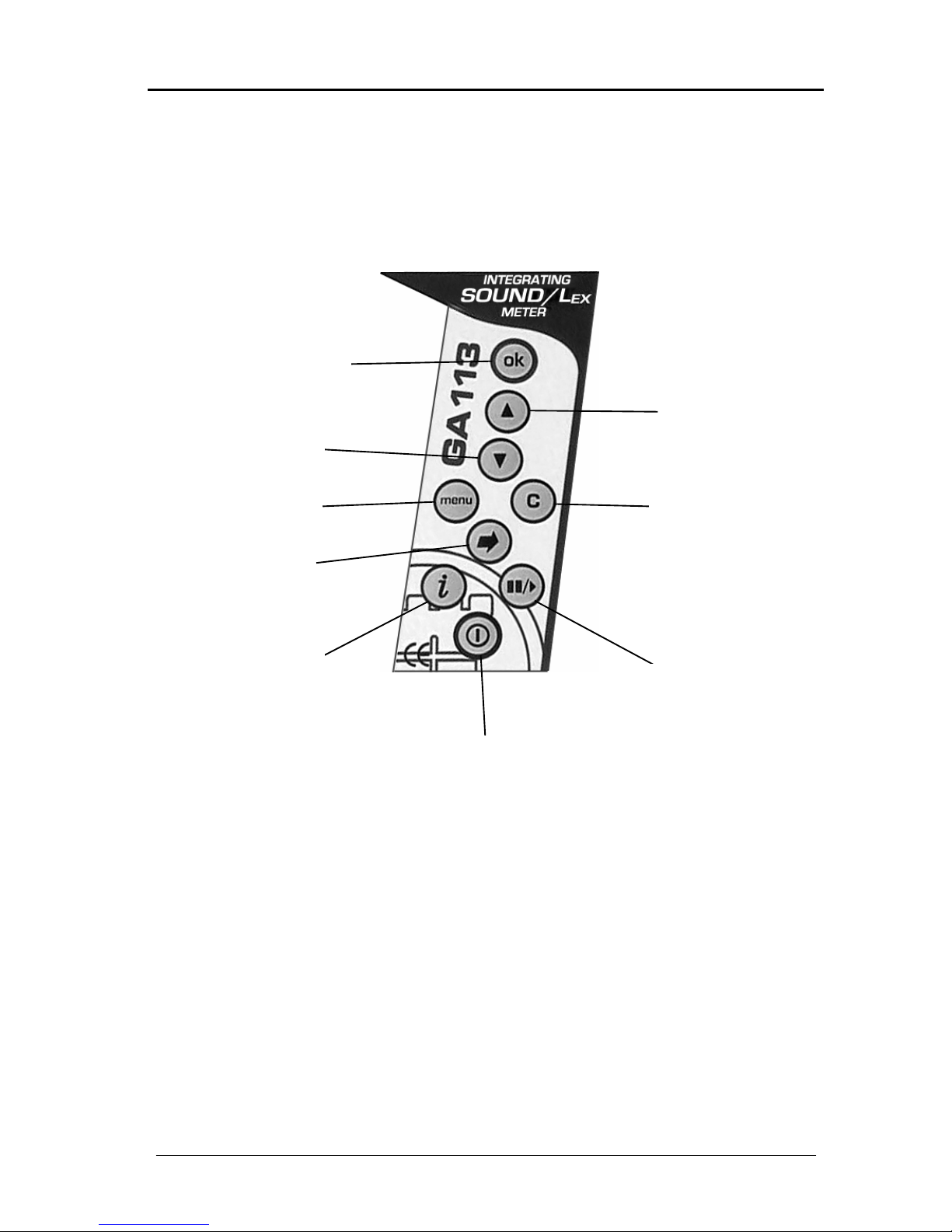
Page 2
Sample Keypad Layout
POWER ON/ OFF
PAUSE/ PLAY
INFORMATION
MENU
OK
UP ARROW
CLEAR
DISPLAY
DOWN ARROW
Page 7

Page 3
Operating Tips
This section is designed to enable you to get the best measurement results
out of your instrument.
• Always check the battery status of the instrument before use.
• Always calibrate the instrument prior to carrying out any
measurements.
• Always CLEAR any previous data recorded prior to taking new readings
and after calibrating.
• The instrument can be set-up in advance to the required frequency and
time weightings/ criterion and exchange rates for the measurements
that you are wanting to carry out.
• To work out the most suitable range to select first take initial samples
of the expected noise levels from the area you will be measuring in.
Then select the range which these levels fall nearest the middle of e.g. if
the levels expected are around 85dB then select the ‘55 – 120 range’
• When taking noise measurements hold the instrument as far in front of
the body as is comfortable to minimise interference of the sound field.
• If using the instrument as a dosemeter with the optional dosemeter
microphone then clip the dosemeter microphone as near to the
operators ear as possible e.g. shirt collar.
• Use the ‘Shift Duration’ feature to automatically calculate the projected
dose functions if your workers shift duration is different to 8 hours.
• To prevent accidental keypresses which could affect the results, use
the LOCK feature to lock-out the keypad.
• Always point the microphone towards the main source of the noise to
be measured (0° reference direction).
• When measuring low noise levels on the bottom range, be aware of the
self generated noise levels of the instrument – see specifications.
Page 8

Page 4
Battery Installation / Check
To prepare the equipment for use a heavy duty alkaline battery type 6LR61
should be fitted, such as a Procell/Duracell MN1604, Ever Ready 6LF22
Gold Seal, or equivalent.
The battery door is located on the bottom left hand side of the instrument.
Open the battery door cover by sliding the cover downward towards the
bottom of the instrument. The cover will now swing open exposing the
battery compartment. Insert the battery observing the correct polarity as
marked on the case wall.
Close the battery compartment door by reversing the procedure above. The
instrument is now ready for calibration and use.
The battery condition is shown on the LCD during the power-on sequence, but
can also be checked at any time by pressing the ‘
i'
key. Pressing the key once
will display the battery status screen, with the battery condition indicated by a
series of vertical bars – 4 bars shows a fully charged battery, while1 bar
shows one that is almost flat. It is recommended that the battery should be
replaced if only 1 bar is displayed. The screen will flash BAT. LOW when the
battery level drops below a sustainable level whilst the instrument is in use. If
this happens, replace the battery.
Microphone
The microphone capsule fitted to your instrument is a high quality class 1
instrumentation grade 1/2 inch capsule.
The GA113 can be fitted with an optional dosemeter microphone assembly
(MK279DP1B) in order that it can be attached to the collar of a noise
exposed worker. Please note that the MK279DP1B assembly is only to be
used when using the instrument as a dosemeter. It is not designed to be used
for taking sound meter readings to Class 1 accuracy.
Measurement microphones by the very nature of their manufacture are
precision components that are easily damaged through incorrect use. Great
care must be taken when using the instrument to ensure the longevity of the
microphone.
PLEASE NOTE THAT THE INSTRUMENT IS NORMALLY SUPPLIED WITH A
PROTECTIVE WHITE PLASTIC CAP COVERING THE END OF THE
MICROPHONE WHEN DELIVERED. THIS CAP MUST BE REMOVED PRIOR TO
USING THE INSTRUMENT.
Page 9
Page 5
Switching the Instrument On & Off
Press and release the POWER button once and the instrument turns on.
Allow the instrument to scroll through its start-up sequence before pressing
any other button; this will take approximately 3 seconds.
When the instrument has completed its start-up sequence the display will
change to LP in PAUSED mode using the settings that were last selected.
To switch off, press and release the POWER button once and the display
goes blank.
PLEASE ENSURE THAT ALL REQUIRED READINGS FROM THE INSTRUMENT
HAVE BEEN COLLECTED BEFORE TURNING OFF THE INSTRUMENT AS ALL
DATA IS LOST WHEN THE INSTRUMENT IS TURNED OFF.
i
(Information) Button
A scrolling sequence exists with this button, repeated pressing of the button
will allow you to scroll through the various information screens available on
your instrument.
BAT ▌▌▌▌
Battery capacity remaining
dBA SLOW Indicates the current frequency and time weighting
SD 08:00 Shows the shift duration setting
90/3 Indicates the current criterion and exchange level
TH -10dB
Shows the threshold setting
(relative to the criterion level)
VER1.04 Indicates the firmware version number
PLAY Indicates the instrument is in PLAY mode
PAUSED
Indicates when the instrument is in pause mode
(only displayed if instrument is in pause mode)
Page 10
Page 6
/ (Pause / Play) Button
Press / button
PAUSED
All functions can be held so that they do not update by pressing the /
button. Once PAUSED the display may be read as normal, allowing the user
to take note of any required readings.
For normal operation of the instrument to continue press the / button
once more and the instrument will briefly show PLAY before returning to the
currently displayed parameter. Please note instrument automatically powers
on in PAUSED mode.
Ö
(Display) Button
A scrolling sequence exists with this button, repeated pressing of the button
will allow you to scroll through the various measurement screens available on
your instrument.
Lp (SPL)
Leq
Lmx
Pmx
Elapsed Time
Lex
Plx
LE
Do%
Pr%
Hr%
P2h
Overload (if triggered)
Under-range / Overload Indication
The display will also flash UR to indicate an under-range condition, or
OVERLOAD to show the range has been exceeded. UR will continue to display
as long as the condition persists. The OVERLOAD indicator will latch as shown
in the table, and can only be reset by pressing the C (Clear) key. (See page
11).
You may leave the display menu by pressing any other button.
Page 11

Page 7
The table below is a breakdown of the display parameters and is
accompanied by a brief description of each one: -
Display Description
93.7dBC Level Pressure (Lp)
Leq 93.7 Displays the LEQ
Lmx 97.3 Maximum Lp
Pmx 98.8 Maximum Peak
00:01:33 Run time duration (Elapsed Time)
Lex 87.1 Displays the Lex (Lep’d)
Plx 78.6
Displays the projected Lex (Lep’d) assuming a shift length
set in the Shift Duration
LE 93.1 Sound Exposure Level (SEL)
Do % 67 Dose (dependent on exchange and criterion)
Pr % 0 Displays the projected DOSE assuming an 8 hour shift
Hr% Dose per Hour
P2h 0.02 Indicates the energy that has been received in Pa
2
hours
OVERLOAD
Indicates if an OVERLOAD has occurred
(Can only be reset by pressing the Clear key)
—–.—
Indicates when values are at 0 e.g. when instrument is first
powered on or after a reset in PAUSED mode.
Page 12

Page 8
Menu Button
A scrolling sequence exists with this button, repeated pressing of the button
will allow you to scroll through the following menu screens available on your
instrument: -
Calibration
It is recommended that the instrument’s calibration is checked and adjusted
where necessary with a calibrator before readings being taken. The
calibration should be re-checked after taking readings to confirm the validity
of the results. The calibrators recommended for use are the Castle
GA601/GA607, which supply typically 94dB/ 104dB (relative to 20μPa
pressure) at a frequency of 1kHz.
Press i to check the battery condition. Replace the battery if the indication is
low.
Press MENU
CAL <OK
Press OK and the instrument will now display the previous calibration level
e.g. >94.0. The calibration will be performed at the selected level e.g. 94.0dB
but may be changed in 0.1 dB steps to match the calibrator output by
repeated pressing of the
or
arrow buttons or in 1dB steps by repeated
pressing of the i / / keys. Ensure the calibrator is attached to the
microphone by gently inserting the microphone into the cavity of the
calibrator. A certain amount of resistance should be felt whilst inserting the
microphone as the o-ring seal on the calibrator forms a seal around the
microphone. Ensure that the calibrator is switched on and set to the chosen
level and all correction factors for atmospheric pressure and microphone
type have been accounted for. The pressure to free-field correction value to
be applied when used with a Castle calibrator GA601, GA607, and a
B&K4231 is as follows:
Castle GA607 Calibrator Pressure To Free Field Correction = -0.2
Castle GA601 Calibrator Pressure To Free Field Correction = -0.2
B&K4231 Calibrator Pressure To Free Field Correction = -0.2
Press OK and the instrument will calibrate to the level of the calibrator. The
display will show CAL WAIT while calibrating to the chosen level. When
calibrated the display will show COMPLETE and will return to LP for the
GA213/215 and DOSE for the GA256. It is recommended that the unit is
then put into PAUSED mode and data is cleared. The instrument is now ready
to take measurements.
If the calibration is interrupted or the input level is not within +/- 3dB of the
chosen reference level then the display will show NO INPUT or CAL FAIL.
Check to make sure the calibrator is switched on and emitting the correct
level before proceeding again as indicated above.
Page 13

Page 9
Shift Duration
It is possible to select an alternative shift duration in hours and minutes of an
employee for calculating projected dose and projected Lex calculations.
Press MENU repeatedly until
SD < OK
is displayed.
Press OK once and the instrument will display the currently selected shift
duration in hours. Repeated pressing of the
/ arrow keys will alter this
figure between 00 and 24. Press OK again and the instrument will display the
currently selected number of minutes. Repeated pressing of the
/ arrow
keys will alter this figure between 00 and 59.
Frequency / Time Weighting
Press MENU repeatedly until
WTG < OK
is displayed.
Press OK and the instrument will display the options available for WTG
SETUP.
To change WTG use either the
or
arrow buttons. Pressing either of these
two buttons allows you to scroll through the four available weighting choices,
A SLOW, A FAST, C SLOW or C FAST.
Note: The symbol > indicates the current selection as you move around the
weighting options
.
Exchange Rate
Press MENU repeatedly until
EXCH < OK
is displayed.
Press OK and the instrument will display the options available for EXCHANGE
RATE Setup.
To change the EXCHANGE RATE use either the
or
arrow buttons.
Pressing either of these two buttons allows you to scroll through the three
available exchange choices, 3dB, 4dB, 5dB
Note: The symbol > indicates the current selection as you move around the
exchange options.
Page 14

Page 10
Criterion
Press MENU repeatedly until
CRIT < OK
is displayed.
Press OK and the instrument will display the options available for CRITERION
Setup.
To change the CRITERION use either the
or
arrow buttons. Pressing
either of these two buttons allows you to scroll through the three available
exchange choices, 80dB, 85dB, 90dB
Note: The symbol > indicates the current selection as you move around the
criterion options.
Threshold
It is possible to select a threshold level for the lower limit of noise levels which
are used to measure dose.
Press MENU repeatedly until
THR < OK
is displayed.
Press OK once and the instrument will display the currently selected
threshold level, relative to the selected Criterion level. Repeated pressing of
the
or
arrow buttons will alter this figure between 0, -5, -10.
Note: The symbol > indicates the current selection as you move around the
threshold options.
Keypad Lock
Press MENU repeatedly until
LOCK?
is displayed.
Press OK and the instrument will lock the keypad. The status of the battery
will be displayed while the keypad is in lock mode
To UNLOCK the keypad press C, OK then C respectively.
The LOCK feature is used to lock the instrument keypad. All keypad functions
are therefore disabled including the POWER button. The function is often
used to avoid inadvertent operation or tampering while the instrument is
being used.
Note: The LOCK function is only available when the instrument is in PLAY
mode.
Page 15

Page 11
C (Clear) Button
The C button is used to reset ALL data* (including overload indication). This
feature should be used prior to taking new readings and after calibration.
Press C
CONFIRM?
Press OK to reset the data or any other button to cancel the request.
The instrument then returns to the previously displayed parameter.
* Use caution when using the C button as reset data cannot be recovered.
Changing Range
A range change can be performed by the use of the /
arrow buttons while
in any of the DISPLAY modes (instrument displaying LP dBA etc).
Press the
or
arrow buttons repeatedly to scroll through the three
available range choices, 35, 55, 75 until the required range comes into view,
then press OK to select.
The instrument will return to the LP screen.
Note: The symbol > indicates the current selection as you move around the
range options.
Page 16

Page 12
Technical Specification
The individual characteristic applies to each instrument unless specifically
worded otherwise.
Instrument Standards:
IEC 61672-1 : 2002 Class 1 Group X
IEC 60651 : 1979 Type 1 + A1:1993 + A2:2000 Group X
BS EN 60651 : 1994 Type 1 Group X
IEC 60804 : 2000 Type 1 Group X
BS EN 60804 : 2001 Type 1 Group X
IEC 61252 : 1993
BS EN 61252 : 1993 + A1:2000
Measurement Parameters:
Lp, Leq, Lmax, Pmax, LE, Pa2h, Lex, Projected Lex, DOSE%, Projected DOSE%,
Dose Per Hour, Elapsed time
Peak Frequency Weighting:
C weighting to IEC 61672-1 Class 1
Time Weightings:
SLOW and FAST according to IEC 61672-1 Class 1, IEC 60651 Type 1
RMS Frequency Weighting:
A and C weightings according to IEC 61672-1 Class 2, IEC60651 Type 2
Level Ranges (dB) for A & C Weighting:
Linear Operating Range, IEC 61672-1:2002
31.5Hz 1kHz 4kHz 8kHz
41.0 – 60.6 41.0 – 100.0 41.0 – 100.0 41.0 – 99.0
55.0 – 80.6 55.0 – 100.0 55.0 – 100.0 55.0 – 119.0
75.0 – 100.6 75.0 – 140.0 75.0 – 140.0 75.0 – 139.0
Page 17

Page 13
Primary Indicator Range
IEC 60651:1979 (1kHz)
41.0 – 93.0
55.0 – 113.0
75.0 – 133.0
(Primary Indicator Range allows for a crest factor of 3 or approximately 7dB)
Linearity Range & Pulse Range
IEC 60804:2000
41.0 – 100.0
55.0 – 120.0
75.0 – 140.0
Level Ranges (dB) for Peak Hold Display
(wrt 1kHz)
63 .0 – 103.0
83.0 – 123.0
103.0 – 143.0
Typical Electrical Self Generated Noise Level:
32 dBA, 38 dBC
Total Measuring Range:
The difference between the lowest possible measurement on the most
sensitive range and the highest level on the least sensitive range at a
frequency of 1kHz.
A Weighted C Weighted
41.0 – 140.0 47.0 – 140.0
Reference Points:
Description Value
Sound Level 94.0dB
Range 55 - 120
Frequency 1kHz
Page 18

Page 14
Starting Points for IEC 61672-1:2002 Linearity Testing:
The following apply at 31.5Hz, 1kHz, 4kHz, and 8kHz: -
35-100 range: 74.0dB
55-120 range: 94.0dB
75-140 range: 114.0dB
Display:
Digital 1 x 8 alphanumeric, digit size 7mm x 5mm Liquid Crystal Display
Display Refresh Rate:
250ms
Detector Characteristics:
RMS and Peak
Warm up time:
< 2 minutes
Electrical Signal Input:
Electrical signals can be applied to the Castle Pocket range of sound level
meters by removing the acoustical microphone and replacing with a dummy
microphone having a series capacitor of 18pF ±2%. The BNC termination is
then used to interface with a suitable signal generator with an output
impedance of 600W at 1kHz.
Maximum Peak to Peak Electrical Signal Input For No Damage:
7 Volts
Upper Frequency for Periodic Acoustic Testing (IEC 616723:2006):
4kHz
Windshield:
The effects of using the KG205 (60mm) windshield
31.5Hz 0.0 1kHz 0.2
63Hz 0.1 2kHz 0.2
125Hz 0.1 4kHz 0.7
250Hz 0.1 8kHz 0.0
500Hz 0.2
The meter conforms to the Standards quoted on Page 12 when fitted with
the windshield.
Page 19

Page 15
Microphone:
ACO ½“ Electret Condenser Microphone Cartridge Type 7146A. Microphone
reference point is the centre of the diaphragm.
Type MK80 (Aco 7146A) Specification
Diameter (inch) 0.5
Response Type Free-Field
Polarisation (V) 0.0
Frequency Range (Hz) 20 - 8000
Sensitivity (mV/Pa) 25.0
Sensitivity (dB re 1V/Pa) -32.0 ±1.5dB
Capacitance (pF) 18.0
Max. Sound Pressure Level (dB) 146.0
Temperature Coefficient (dB/°C) -0.01
The pressure to free-field correction value to be applied when used with a
Castle calibrator GA601/GA607 or B&K4231 is as follows: -0.2dB
The capsule can be removed by unscrewing anti-clockwise although great
care must be taken when doing this to avoid damage to either the capsule or
the instrument. Re-fitting is a reverse of the above.
Type MK80 (Aco 7146A) Typical Microphone Response
16Hz 0.0 1kHz 0.0
31.5Hz 0.0 2kHz 0.0
63Hz 0.0 4kHz -0.1
125Hz 0.0 8kHz -0.7
250Hz 0.0 16kHz 1.0
500Hz 0.0
Typical Actuator to free field correction factors(dB) of an MK80
(Aco 7146A) microphone (Based on 500Hz = 0)
250Hz 0.0 2.5kHz 1.0
315Hz 0.0 3.15kHz 1.2
400Hz 0.0 4kHz 1.5
500Hz 0.0 5kHz 2.0
630Hz 0.0 6.3kHz 2.5
800Hz 0.0 8kHz 3.8
1kHz 0.0 10kHz 4.6
1.25kHz 0.2 12.5kHz 6.8
1.6kHz 0.4 16kHz 8.8
2kHz 0.5 20kHz 10.0
Maximum SPL at the Microphone for No Damage:
146 dB
Page 20

Page 16
Calibration Reference Conditions:
Sound Field Free Field
Air Temperature 23°C (73°F)
Relative Humidity 50%
Atmospheric Pressure 101.325 kPa
Sound Pressure Level 94.0dB
Reference Level Range 55 – 120dB
Reference Frequency 1kHz
The reference direction of incidence for all microphones is perpendicular to
the front face (diaphragm surface) of the microphone.
Operating range:
0°C to +40°C
Warning: DO NOT subject the instrument to temperatures greater than 70°C
or less than -20°C for any length of time.
Effect of Temperature:
Accuracy better than ± 0.5 dB over the range 0 to +40°C
Effects of Humidity:
Less than 0.5 dB over the range 25 to 90% relative humidity (provided there
is no Condensation), relative to the value at 50% relative humidity and 40°C.
Storage range: 0 to 90% relative humidity in the absence of condensation
Effects of Vibration:
From 20Hz to 1kHz at 1ms
-2
no noticeable effect
Magnetic Field:
No noticeable effect
Operator Presence in Free Field:
No noticeable effect when operator standing more than 2 metres behind
instrument.
Batteries:
1x MN1604 (size PP3) alkaline cell
Life Expentancy: 12 hours continuous use (approx)
Min Battery Level: 5.4V DC
Max Battery Level: 9.4V DC
Page 21

Page 17
Overall Dimensions:
210mm x 60mm x 35mm (approx.)
Overall Weight including Batteries:
220g
Case Reflections:
GA113 using the Aco 7146A microphone
Stalk length 75mm from front of microphone grid to top of case body
Frequency (Hz) Case Effect (dB) Frequency (Hz) Case Effect (dB)
31.5 0.0 800 0.2
40 0.0 1000 0.0
50 0.0 1250 -0.3
63 0.0 1600 -0.2
80 0.0 2000 -0.5
100 0.0 2500 0.4
125 0.0 3150 -0.2
160 0.0 4000 -0.2
200 0.0 5000 0.1
250 0.1 6300 0.1
315 0.1 8000 0.0
400 0.1 10000 0.0
500 0.1 12500 -0.2
630 0.1 16000 0.0
Page 22

Page 18
AC Output:
Vout ≈ 16.4mVrms at 94.0dB
The output is un-weighted and not affected by the measurement range.
DC Output:
Vout ≈ 40mV/dB
Vout ≈ 3.3 – [((top of range +3) - (reading in dB)) x 0.04]
Output affected by: -
• Frequency Weighting
• Measurement Range
Output Socket:
Both AC and DC outputs require load impedance's to exceed 10kΩ, however
load impedance's > 100KΩ are recommended.
Radio Frequency Fields:
The GA113 instrument falls into classification X for the susceptibility to Radio
Frequency Fields.
DC Output
GND
AC Output
Front View
Page 23

Page 19
EC Declaration of Conformity:
The CE marking of this Castle Product indicates compliance with the EMC Directive.
Castle Group Ltd declares that the: -
•
GA113 Pocket Sound Level Meter
has in accordance with the following Electromagnetic Compatibilty Directives: -
•
89/336/EEC
been designed and manufactured to the following specification:
•
EN61326-1:1997 + A1:1998
with the following Tests:
•
Radiated Emissions: EN55022:1995 Class: B
•
ESD: EN61000-4-2:1995 Levels: ±4kV (C) , ± 8kV (A)
•
Radio-frequency EM field amplitude mod: EN61000-4-3:1996 Level: 3V/m
No differences in radio frequency emissions are apparent between the available ranges on GA113
instrument.
We hereby declare that the instruments named above have been designed to comply with the relevant
sections of the above referenced specifications, and that the above named instruments comply with all
essential requirements of the specified Directives.
Page 24

Page 20
Instrument Disposal:
The symbol shown here can be found on your instrument and
means that the product is classed as electrical or electronic
equipment and should be disposed of at the end of its life separately
to your commercial or household waste.
The Waste of Electrical and Electronic Equipment Directive (2002/96/EC)
has been established to help reduce the influx on landfill sites and effectively
treat hazardous substances by using best practices for the recovery and
recycling of products.
There are various collection systems in place within the EU for the disposal of
your product. To find the nearest UK waste recyling point in your area, enter
your postcode in the website www.recycle-more.co.uk
For more information please contact your local authority, the dealer where
you purchased your product or Castle Group Ltd.
Accessories:
GA607 – Dual Level Calibrator (Class 1)
MK279DP1B – Dosemeter Plug-in Microphone
KG204 – Dosemeter Windshield
KG205 – Sml Windshield
KA010 – Sml Attaché Case (Holds Instrument and Calibrator)
6LR61 – 9V Battery (Pack of 10)
Instrument Details:
For your records and for future correspondance with Castle Group Ltd
regarding your instrument, please complete the following details: -
Instrument Serial Number
Purchase Date
Page 25

Page 21
Warranty and After Sales Service:
Castle Group Ltd design and manufacture precision instruments, which if
treated with reasonable care and attention should provide many years of
trouble free service.
In the event of a fault occurring, during the warranty period, the instrument
should be returned to Castle Group Ltd, in its original packaging, or to an
authorised agent. Please enclose a clear description of the fault or symptom.
Details of the warranty cover are available from Castle Group Ltd or an
authorised agent.
All instruments are designed to meet rigid British and International
Standards. An annual calibration is recommended to ensure that these high
standards are maintained. This is particularly important for cases in which
instrument readings are to be used in litigation or compliance work.
For warranty and service return to: -
The Service Department
Castle Group Ltd
Salter Road
Cayton Low Road Industrial Estate
Scarborough
North Yorkshire
YO11 3UZ
Telephone: +44 (0)1723 584250
Fax: +44 (0)1723 583728
Email: techsupport@castlegroup.co.uk
Web: www.castlegroup.co.uk
Any misuse or unauthorised repairs will invalidate the warranty.
Damage caused by faulty or leaking batteries is not covered by the warranty.
Page 26

Page 22
Trouble Shooting:
Question Answer
My instrument will not turn on?
Check that there is a battery fitted to the
instrument.
Check that the battery is not flat.
What is this white plastic cap
fitted to the top of the
microphone?
This is a protective cover for the sensitive
microphone. You must remove it before
using the instrument.
Where have my results gone?
The GA113 does not have a backup
memory so all readings are lost when the
instrument is switched off. Always take a
note of important readings before
switching off the instrument
My instrument is on but will not
respond to keypad presses?
Have you locked the keypad – see page 10
for details on this function.
I keep getting CAL FAIL when
t
rying to calibrate my instrument
– what am I doing wrong?
Is the instruments microphone properly
inserted in the calibrator?
Is the calibrator switched on and working?
Has the instrument and/or calibrator
been knocked or moved as the calibration
routine is taking place?
Has the microphone been damaged?
What is the black o-ring inside my
calibrator’s cavity for?
The o-ring is essential to seal around the
microphone stabilising the pressure in the
calibrator’s cavity. If the o-ring is missing
and/or damaged the instrument will not
calibrate properly (see above).
When taking readings the display
is constantly flashing *UR* –
what does this mean?
This means that the noise you are
measuring is below the bottom of the
range you have the instrument selected to.
Try selecting a lower range (see page 11
for details).
My readings are within range but
I keep getting **OL** flashing
on the screen – why is this?
The overload is triggered by the Peak
reading whereas LP and LEQ are rms
figures which are lower. Some noises
feature very high peaks compared to the
rms.
Page 27

Page 23
Question Answer
My instrument has stopped
responding to noise since I
calibrated it?
Is the microphone capsule loose on the
instrument? When removing the
microphone from the calibrator it is
possible to accidentally unscrew the
microphone.
Why is my projected LEX not the
same as the LEQ?
The shift Duration (see page 9) may be set
to a time other than 8 hours
After taking my readings the
figures are a lot higher than
expected?
Did you clear the memory after
calibration?
Disclaimer:
Whilst every effort is made to ensure the accuracy and reliability of both the
instrument described and the associated documentation, Castle Group Ltd
makes no representation or warranties as to the completeness or accuracy
of this information.
Castle Group Ltd assumes no responsibilty or liability for any injury, loss or
damage incurred as a result of misinterpreted or inaccurate information.
Any documentation supplied with your product is subject to change without
notice.
HB/0113/005/A5 Rev B
 Loading...