

Page 1
Page 2

Thank you for buying a Castle product, I am sure you will find both
the goods and the service to be of the highest quality but if not, then
please feel free to write to me personally and I will ensure that your
needs are dealt with immediately.
This manual is designed to show you the operation of the goods you
have purchased and a very brief insight into acoustics itself. If you
would like to become a competent person in the eyes of the law, then
you may like to know more about our Competent persons training
course for the Noise at Work Regulations.
It is my intention for Castle Group Ltd to provide a complete range of
Noise and Vibration products and Services of the highest standard. If
you would like to know more about any of our other products and
services then please complete the reply paid card in this manual and
return it to us for prompt action or telephone on +44(0)1723 584250.
Simon Bull
Sales and Marketing Director
Page 3

Precautions
Operate the unit only as described in this manual.
• The GA112 is a precision instrument. Protect the instrument from shocks and
vibrations.
• Use only the microphone/preamplifier as supplied with the unit. Take special
care not to touch the microphone top as it can easily be damaged.
• Ambient conditions for operation of the unit are as follows : temperature
range - 10°C to +50 °C, relative humidity 30 to 90%.
• Protect the unit from water, dust, extreme temperatures, humidity, and direct
sunlight during storage and use. Also keep the unit away from air with high
salt or sulphur content, gases, and stored chemicals.
• Always turn the unit off after use. Remove the batteries from the unit if it is
not to be used for a long time (a week or more) . When disconnecting the cable, always unscrew the plug and do not pull the cable.
• Clean the unit only by wiping it with a soft, dry cloth or, when necessary,
with a cloth lightly moistened with water. Do not use any solvents, cleaning
alcohol or chemical cleaning agents.
• Take care that no conductive objects such as wire, metal scraps, conductive
plastics etc. can get into the unit.
• Do not try to disassemble or alter the unit. Otherwise type certification will
become invalid. In case of an apparent malfunction, do not attempt any repairs. Note the condition of the unit clearl y and contact the supplier or Castle
Group direct.
NOTE
Castle Group sound level meters are electronic instruments and should be handled
accordingly. Damage caused by misuse, abuse and leaking batteries is not covered by the warranty. If the instrument fails to function correctly, firstly check the
condition of the batteries. When changing the batteries, replace all three at any
one time. In order to conserve battery life do not leave the instrument turned on
when not in use.
Page 4

CONTENTS
TITLE PAGE NO
Instrument Introduction 5
Battery Installation 6
Preparation of Equipment and Controls 7
Calibration 12
Measuring Sound Levels 13
Measuring Maximum Sound Levels 14
Use of Filters for Octave Band Analysis 15
Use of the Output Socket 16
Instrument Description 18
Circuit Description 19
Environmental Effects 19
Technical Specification 20
Warranty and After Sales Service 24
Page 5
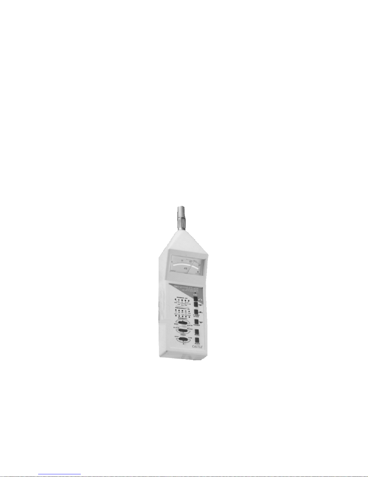
Instrument Introduction
The instrument covered by this handbook is an analogue sound level
meter built into our award winning, tough die-cast body, which is
both stylish and ergonomically designed. The instrument has ‘A’
weighting and ‘LIN’ (linear) frequency responses as well as a set of
ten octave band filters. The filter’s ‘AUTO’ facility allows a chart
recorder to display the results of a noise spectrum analysis. ‘SLOW’,
‘FAST’ and ‘PEAK’ responses are available. A maximum hold button, ‘MAX’, allows the accurate recording of the ‘maximum rms’ of
a transient noise event. The instrument conforms to the relevant sections of BS5969, IEC651, ANSIS1.4, BS2475 and BS EN60651
standards.
5
Page 6
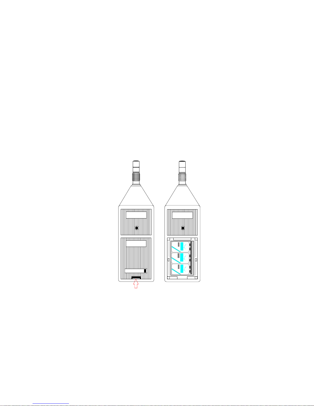
Battery Installation
To prepare the equipment for service batteries must first be fitted. Remove the lower rear black plastic ‘clip in’ cover by pushing the locking
clip at the foot of the instrument upwards and push the cover out; this will
expose the battery compartment. Connect three new 6D22 type batteries,
preferably heavy-duty types which give greater economy and are less
prone to leakage, to the snap conductors ensuring correct polarity and
making sure that each stud is a firm fit. Replace the battery cover and
push the retaining clip firmly home. The instrument is now ready for calibration and use.
Re m o v e C o v er
to change B atter ies
Serial No. 012345
Release the spring catch
and remove the battery
compartment cove
r
Tel: (0723) 584250 Fax: 0723 583728
Castle Associates
Lim ite d
Salter Roa d, Scarborou gh,
England.
Serial No. 012345
6
Page 7
Preparation of Equipment and Controls
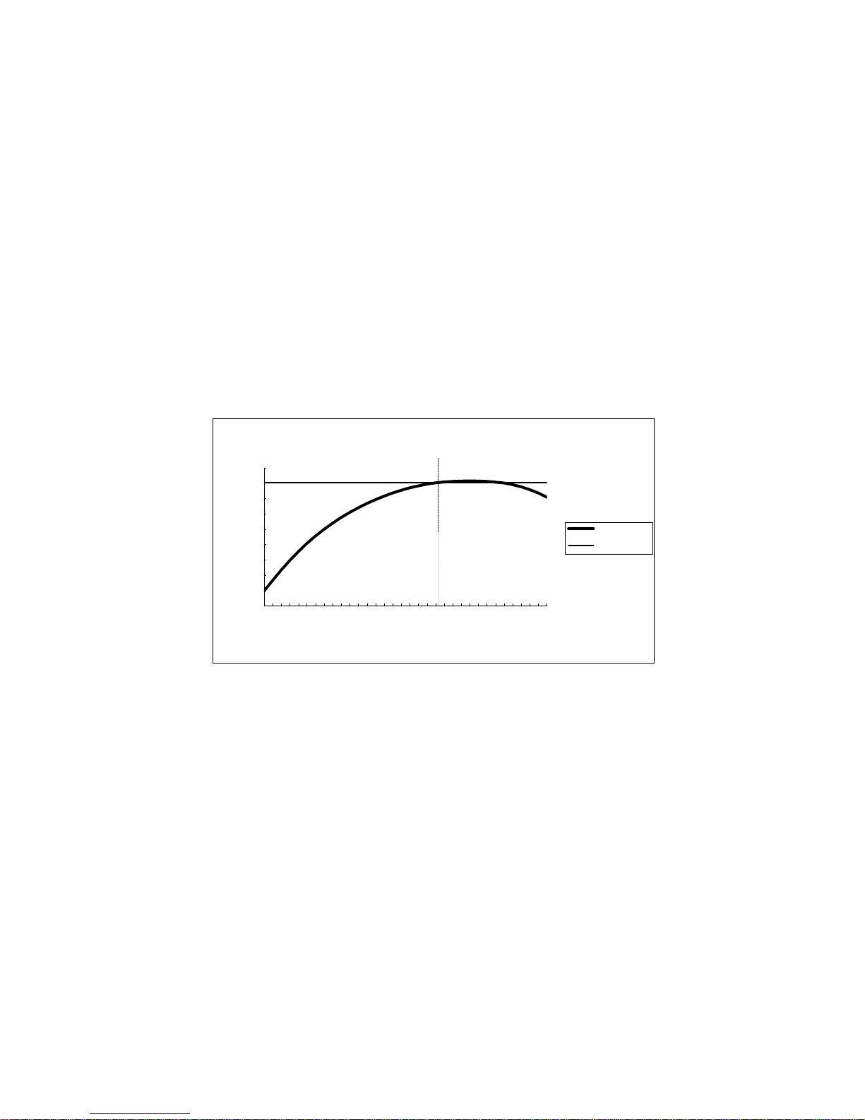
Power/Weighting Switch
This is a three-position switch labelled OFF-A-LIN. In the OFF position all power is removed from the instrument. The ‘A’ position
allows sound levels to be measured with ‘A’ weighting, (see figure
1). For a linear or ‘flat’ frequency response the LIN is used.
Figure 1 – ‘A’ weighting curve
Battery Check Button
A push button labelled BATT is provided to allow periodic checking of the battery condition. A meter deflection in the area marked
‘BATT’ shows the batteries are in good condition.
'A' AND LINEAR FREQUENCY WEIGHTINGS
-80
-70
-60
-50
-40
-30
-20
-10
0
10
10
100
1K
10K
Frequency/ Hz
SPL/d
B
'A' Weighting
Linear
7
Page 8

Peak/Slow/Fast Switch
This three position slide switch, labelled SLOW-FAST-PEAK,
determines the damping coefficient of the analogue meter. The
SLOW position sets the instrument for the standardised ‘slow’ meter
response with a time constant of 1 second. In the fast setting the instrument has a time constant of 125ms for the standardised fast meter
response. When the meter is used in the PEAK mode, the meter has
minimum damping and allows quick acting transient sounds to be
shown.
Maximum Hold Button
The MAX button is a momentarily acting push button which holds
the maximum sound level whilst the button is depressed. Once the
button is released the meter returns to normal operation. This facility
is very useful for capturing the maximum rms sound level of transient sound events.
Filter Mode Switch
The octave band filters can be used by placing the switch in either
the MAN or the AUTO position. When in the OUT position the meter operates as a normal sound level meter with a ‘linear’ (‘flat’) or
‘A’ weighted response. When using the filters the ‘A’ weighted response can also be used if desired.
The filters can be used in two different modes, MAN or AUTO. In
the MAN (or manual mode), the centre frequency of the filters is
changed by depressing either of the select buttons, ‘frequency up’ or
‘frequency down’. The frequency of the filter currently in operation
is displayed by means of ten LED’s (light emitting diodes) ,
positioned on the front panel.
8
Page 9

Ten standard centre frequencies are used 31.5Hz, 63Hz, 125Hz,
250Hz, 500Hz, 1kHz, 2kHz, 4kHz, 8kHz and 16kHz. These allow the
engineer to gain a clearer ‘picture’ of the frequency distribution of the
noise. Typical responses of these filters are shown below (Figure 2).
A memory facility is provided to allow the user to switch the filters
‘in’ and ‘out’ and still remain on the same frequency.
Figure 2 – Filter Responses
The filter’s AUTO mode facility allows a chart recorder to give an
octave band plot for a ‘hard’ copy of the noise spectrum. The frequency control buttons are assigned different ‘roles’ in this mode,
labelled RESET and START-STOP.
Depressing the RESET button at any time causes the filter frequency
to reset to the lowest centre frequency, 31.5Hz. By depressing the
START-STOP button once, the filter will step up through all the frequencies in turn, staying on each frequency for 3 to 4 seconds. This
allows enough time for the meter circuitry and chart recorder to settle.
Immediately after depressing the START-STOP button, and between
each change of frequency, a short downward stroke is drawn onto the
chart recorder to enable each octave band sound level to be separated
and therefore clearly seen.
9
Page 10

By depressing the START-STOP button a second time, the filter will
stop on it’s current frequency. If the filter is left running in the
AUTO mode when it reaches the highest centre frequency, it will remain there until the reset button is depressed.
Ranging Buttons and LED Indicators
The range of the instrument is indicated by a series of five LED’s.
To change the range ‘up’, depress the button marked with an up arrow, to change the range ‘down’, the button marked with a down arrow is depressed. The five base ranges on the GA112 are shown below (figure 3).
Figure 3 – Table of available ranges
As can be seen from the table above, a 10dB overlap occurs between
the ranges, this means that if a meter reading in the bottom ‘third’ is
observed the range can be changed down.
Generally it is better to select a range which gives you the greatest
deflection on the meter. However if the meter reading passes fullscale deflection, or the overload LED (found in the lower right corner of the meter) indicates an overload, the instrument must be
changed up a range.
Base range Meter range
30dB 30-60dB
50dB 50-80dB
70dB 70-100dB
90dB 90-120dB
110dB 110-140dB
GA112
10
Page 11

Calibration Control
This is a screwdriver-adjusted control, which alters the input sensitivity of the instrument. A small flat bladed screwdriver, no larger
than 2mm, should be used when calibrating the instrument. Calibration should only be carried out in conjunction with a known
sound source.
Output Socket
This socket is designed for use with chart recorders and similar
equipment. A 3-pin LEMO connector (type FGGOB303CLAD52Z)
must be used to connect external equipment.
Overload LED
This indication is on the meter scale and warns when the selected
range is exceeded. In such an overload situation, frequency analysis
is distorted as the signal is clipped. Generally this can be avoided
be choosing a higher range.
Please note the overload indicator detects the overload conditions in
all critical points of the instrument and it is possible to have such a
situation without a high reading shown on the analogue meter.
11
Page 12

Calibration
The calibrator recommended for use with the GA112 is the Castle
GA607, a dual level calibrator which supplies 94dB and 104dB
(relative to 20 uPa pressure) at a frequency of 1kHz.
Procedure
1 Turn ‘on’ the instrument by switching it into ‘A weighting’ mode
and check the conditions of the batteries by depressing the BATT
button.
2 Place the filter control switch in the OUT position, ideally the
response switch should be placed in the FAST position.
3 Turn the calibrator on to the 94dB and check that the battery status is
as per the calibrator manual. A 1kHz tone should be audible at this
time.
4 Position the calibrator firmly over the microphone using a
“clockwise” twist.
5 Place the meter on its 70 d B ran ge and adju s t th e CAL control un ti l
the meter reads 94dB.
6 If using the Castle GA607 calibrator, it is also possible to check the
sound level meter on its 90dB range, switch the calibrator to the
104dB position and check that the reading is within 0.4 dB. This
serves as a cross check for the type 1 instrument.
7 Two additional tests can be carried out in order to establish correct
calibration of the instrument. Firstly at the 1kHz calibration
frequency, switching the instrument to the LIN weighting mode, this
should give the same sound levels as the ’A’ weighting mode (within
1dB).
12
Page 13

Secondly by keeping the weighting in the LIN mode and
putting the filter into the MAN mode (as detailed on pages 8 & 9),
on its 1kHz centre frequency, the calibration should be within
+0.5dB and –1dB.
Measuring Sound Levels
Use as a normal sound level meter
1 Turn on the meter by selecting the ‘A’ weighting or LIN
response, and switch the filters OUT.
2 Check the battery voltage and the calibration of the sound
level meter.
3 Select the 110dB range.
4 Point the instrument towards the source of the sound to be
measured.
5 Progressively step down the ranges until a reading in the
upper two thirds of the meter scale is obtained.
6 If it proves difficult to read the meter because of excessive or
unsteady needle movement, switch the response to SLOW.
7 Record the sound level reading as the meter deflection
(between 0 and 30), plus the selected range, in dB’s if LIN or
in dB (A)’s if ’A’ weighted.
Eg. A sound level of 94.0dB(A) would appear as a needle deflection of 24, while using the unit on 70dB range.
13
Page 14

Measuring Maximum Sound Levels
1 Turn on the meter by selecting A weighting or LIN
response, and switch the filters OUT.
2 Check the battery voltage and the calibration of the
sound level meter.
3 Select a suitable range so that the maximum expected
sound level would be registered on the meter without
causing it to go off the scale. By trying several ranges
the most suitable will soon be found.
4 Set the response switch to FAST or PEAK.
5 Point the instrument towards the source of the sound to
be measured.
6 Press the MAX button and hold it down until the
transient sound has occurred and the meter has reached
its maximum value. The button must be held until the
reading has been recorded, as once the button is
released the meter returns to normal operation.
14
Page 15

Use of Filters for Octave Band Analysis
1 Turn on the meter by selecting ‘A’ weighting or LIN
response and switch the filters to MAN.
2 Check the battery voltage and calibration of the sound
level meter.
3 Select the lowest filter frequency (31.5Hz) and the
100dB range.
4 Point the instrument towards the source of the sound to
be measured.
5 Progressively step down the ranges until a reading in
the upper two thirds of the meter scale is obtained.
6 Record the reading and select the next centre frequency.
Repeat the measuring procedure until the highest filter
frequency (16kHz) is reached.
It is possible to switch the filter OUT and back to MAN
again and still maintain the last selected centre
frequency.
7 With the results obtained an octave band plot can be
drawn. This plot gives the spectrum of the noise source
being measured, from which the nature and cause of the
noise can be determined and cured.
15
Page 16

Use of the Output Socket
The GA112 is equipped with a three-pin lemo connector on the right
hand side of the instrument. The connector provides an AC and a
DC signal output (see figure 4).
The AC output is a logarithmic output and is direct representation of
the sound present at the microphone. This output is actually suitable
for recording the noise by means of a tape recorder for analysis at a
later date. A full-scale deflection on the meter corresponds to a
120mV rms signal into a 10kohm loading.
The DC output is a linear signal suitable for chart recorders. A voltage of 1.5V is given for a full-scale deflection on the meter, zero on
the meter corresponds to approximately zero volts. The DC output is
designed to drive a load of 10kohm.
A suitable connector for the lemo socket is the, LEMO type
FGGOB303LAD52Z.
Figure 4 – LEMO socket connections
16
Page 17

When using a chart recorder the following settings can be used as an initial guideline: -
Paper speed (or X-axis travel) 0.5cm/sec.
Sensitivity (or Y-axis trav el) 200mV/cm (using 180mm paper)
The following procedure can then be used: -
1 Connect the chart recorder (or X-Y plotter) to the sound level meter.
2 With the filters switched OUT measure the sound level .
3 Keeping the meter on the same ‘range’ switch the meter to the AUTO mode. Press
RESET and the 31.5Hz LED should be lit.
4 Start the chart recorder moving and when ready press the START/STOP button
once. A downward ‘stroke’ of recorders pen will indicate w her e the star t was, and
also each change of frequency.
5 When the filter has reached the top (16kHz) frequency it will remain there. To
repeat the procedure depress the RESET button in order to start from 31. 5Hz fre
quency again. Pressing the START-STOP button during the stepping procedure
will STOP the filter on its current centre frequency , pressing the button once more
will START the stepping once more. The START-STOP button therefore acts as an
effective ‘pause’ facility.
Note
The horizontal (or X-axis) is logarithmic frequency in Hz, or k Hz corresponding to the ten filter centre frequencies as indicated on the front panel of the sound level m eter. The vertical
scale (or Y-axis) is in dB’s and ther efore linear. Some calibration and setting up of the chart
recorder will be necessary if direct readings are to be taken from the rulings on the chart recorder paper.
17
Page 18

Figure 5 – Block diagram of instrument
OCTAVE
BAND
FILTERS
LED DISPLAY
FREQUENCY
SELECT
A
WEIGHTING
amp
AC OUTPUT
OVERLOAD
DETECTOR
OVERLOAD
LED
amp
SLOW, FAST, PEAK
BATTERY
CHECK
MAX
HOLD
DC OUTPUT
amp
METER
PRECISION
RMS TO LOG DC
CONVERTER
amp amp
CALIBRATION
RANGE CONTROL
LED DISPLAY
FILTER OFF,
MAN. AUTO
Instrument Description
18
Page 19

Circuit Description
The AC voltage coming from the microphone is amplified in three amplifier stages. The first stage being an ultra-low noise pre-amplifier,
this is followed by an amplifier variable gain for calibration. These
amplifiers also form the ranging circuit calibrated in 20dB steps.
Range changing logic selects the desired attenuation and controls the
gain of the pre-amplifiers, indicating the range on a series of LED’s.
This is then fed into a series of octave band filters which can be
switched in and out when required and then through the ‘A’ or LIN
weighting network. The frequency changing logic selects the filter frequency and displays it by way of LED’s.
This signal is passed to the true rms converter and logged. This is then
converted to a linear signal in order to drive the meter, which is linearly
scaled in dB. A maximum hold facility is used to maintain the maximum meter deflection while readings are being taken and a battery
check facility also drives the meter in order to monitor the condition of
the batteries.
Environmental Effects
The GA112 is designed for operation between the temperature limits
of –10°C to +50°C. The unit may be stored, without batteries, between –20°C and +60°C, but should not be subjected to temperatures
beyond these ranges for long periods.
The instrument may be subjected to continuous vibration of up to 3g
without damage.
19
Page 20

Technical Specification
Measuring Range
Detector
Characteristics: RMS
Signal to noise ratio: >5dB at bottom scale
Crest factor capability: 13dB at FSD
Frequency weighting
‘A’ to BS EN 60651
LIN to BS EN 60651
Time weighting
Slow to BS EN 60651 Type 1
Fast to BS EN 60651 Type 1
Peak Onset time 2.3mS as specified by
BS EN 60651
Display
Type: Analogue moving coil meter with overload
LED indication.
Scale: 0 to 30dB mirrored linear scale with battery
condition indication and overload indication.
Range Measuring Range Max. Peak Level
30 30-60dB 73dB
50 50-80d|B 93dB
70 70-100dB 113dB
90 90-120dB 133dB
110 110-140dB 153dB
20
Page 21

Display Parameters
Sound Pressure Level either ‘A’ or Linear weighted with or without
Octave Band Filters. Battery condition indication.
Filters
Built in Octave Band Filters to BS EN 61260 : 1996
Filter centre frequencies 31.5Hz, 63Hz, 125Hz, 250Hz,
500Hz, 1kHz, 2kHz, 4kHz,
8kHz, 16kHz.
Switch selectable OFF/MANUAL/AUTO.
Overload
Positive overload condition shown when Crest Factor is exceeded
(see also description on page 11).
Output Socket
AC Output: 120mV rms for FSD.
Output impedance approx 600ohm.
Load impedance 10kohm or more.
Short circuit protected.
DC Output: 1.5V for FSD.
Output impedance approx 600ohm.
Load impedance 10kohm or more.
Short circuit protected.
Connector: Lemo FGG0B303CLAD52Z
Microphone/Preamp
Pre-polarized ½” (12.7mm) Condenser Microphone
Sensitivity 12mV/Pa
Capacitance 15pF
Preamp output impedance 550R
21
Page 22

Calibration
Acoustic using GA607 (or GA602) at 94 dB or 104db at 1 KHz
Potentiometer adjustment.
Batteries
Type: 3xPP3
Life: >40 hours at 3hrs/day
>12 hours continuous
Temperature
Operating range: -10oC to +50oC
Storage without batteries: -20oC to +70oC
Effect of temperature: <0.5dB from –10oC to +50oC
Humidity
Operating range: 30% RH to 90%RH
Effect of humidity: <0.5dB
Vibration
A 40Hz 1m/s vibrating force produces <0.5dB error.
Magnetic field
80A/m (1 Oersted) at 50Hz produces <0.5dB error
Standards
BSEN60651
IEC651 Type1
BS5969 Type 1
22
Page 23

Overall Dimensions and Weight
280x85x60mm
800g with batteries
Accessories available
KA003 Attaché style carry case with tripod*
KA005 Shoulder bag carrying Case
GA607 Dual level acoustic calibrator 94dB and 104dB at 1kHz
*Tripod purchased separately
23
Page 24

Warranty and After Sales Service
Castle Group design and manufacture precision instruments, which if treated
with reasonable care and attention should provide many years of trouble free
service.
In the event of a fault occurring, during the warranty period, the instrument
should be returned to Castle Group Ltd, in its original packaging, or to an
authorised agent. Please enclose a clear description of the fault or symptom.
Details of the warranty cover are available from Castle Group Ltd or an
authorised agent.
All instruments are designed to meet rigid British and International
Standards. An annual calibration is recommended to ensure that these high
standards are maintained. This is particularly important for cases in which
instrument readings are to be used in litigation or compliance work.
For warranty and service return to:
The Service Department
Castle Group Ltd
Salter Road
Cayton Low Road Industrial Estate
Scarborough
North Yorkshire
YO11 3UZ
Telephone UK: (01723) 584250
INT: 44 1723 584250
Fax UK: (01723) 583728
INT: 44 1723 583728
Any misuse or unauthorised repairs will invalidate the warranty.
Damage caused by faulty or leaking batteries is not covered by the warranty.
H:\Research & Development\Manuals\GA112 manual
24
HB/0112/006/A5 Issue B
 Loading...