

Page 1

Copperhead 10 Online Drivers Ed Guide .docx
Castle Creations 2021 ©
Castle Technical support
You may contact our world-class technical support department via e-mail anytime or by
phone. Please visit Castle Creations website for technical support hours.
Website: www.castlecreations.com/support
E-mail: home.castlecreations.com/contact-support
Phone: (913) 390-6939, option #1. Mon-Fri, 9AM-4PM CST.
WARNING: This is an extremely powerful brushless motor system. We strongly recommend
removing the pinion gear from the motor for your own safety and the safety of those around you
before performing calibration and programming functions. Please keep your hands, hair, feet, pets,
fuzzy purple shorts, and garden gnomes clear from the gear train, axle shafts, wheels, and tires of
an armed high-performance system.
DO NOT hold the vehicle in the air and run it up to full throttle. Rubber tires will “grow” to
extreme size on a high-speed vehicle. Tire failures at speed can cause serious injury! Make sure
your tires are securely glued to the wheels and check them often.
ALWAYS disconnect the battery from the ESC when you are finished enjoying your vehicle.
The switch on the ESC controls the power that is delivered to the receiver and servo(s). The
controller will always draw current when it is connected to the battery and will completely
discharge batteries if they are connected for long durations. This may cause failure of your
batteries. Castle Creations is not responsible for any damage as a result of batteries left plugged
in to your ESC. Your Castle ESC is programmed to sound a tone every ten seconds to remind you
that it is still powered.
Always monitor your ESC and motor temperatures during the first run after modifying your
system to ensure they stay within the safe operating limits.
COPPERHEAD 10 DRIVERS ED GUIDE
095-0412-00 REVISION
DATE 4/29/2021
Page 2

Copperhead 10 Online Drivers Ed Guide .docx
Castle Creations 2021 ©
• Getting Started
• Introduction
• A Word about Batteries
• Connectors and Power Wiring
• Motor Wiring
o Brushless Motor Wiring, Sensorless Motors
o Brushless Motor Wiring, Sensored Motors
o Brushed Motor Wiring, Reversing
• Radio Connection
• Audible Alerts
• Data Logging Lite
• Tuning with Castle Link
o Castle Link and Windows PC
o Castle B-Link Adapter and iOS/Android App
o Field Link Programming Card
o Transmitter Programming
• Troubleshooting
• Warranty Information
• Transmitter Programming Reference
• Audible Alert Reference
• Castle Technical Support
Getting Started
• Solder a high-quality battery connector to the ESC. See “Connectors and Power
Wiring”
• Mount the ESC and motor into the vehicle.
• Connect motor to the ESC. See “Motor Wiring”
• Plug in the ESC RX lead. See “Radio Connection”
• Calibrate your ESC to your radio. See “How to Calibrate the ESC”
You are now ready to go!
Easy to Use, Sophisticated Enough to Win Everything
Page 3

Copperhead 10 Online Drivers Ed Guide .docx
Castle Creations 2021 ©
Castle controllers are extremely simple to set up and optimize for your application. Most
users may simply plug the controller into their motor, radio, and battery and run it
immediately.
Advanced users may wish to access the incredible tuning features using their Windowsbased PC and the Castle Link USB adapter via a standard USB-mini cable. With Castle Link
software you can tune the ESC exactly with point-and-click ease!
Please make sure to read this guide completely to get the most from your Castle
ESC.
A Word about Batteries
As with any extremely high-powered electric power system, the primary limitations to
ultimate vehicle performance are the batteries and connectors. Use the best batteries and
connectors that you can find. The better the batteries, the more punch you’ll have!
Minimum recommended capacity is 5000mAh+. Do not use 20C continuous discharge
batteries. We recommend 30C continuous discharge or higher (or high quality 25C
batteries such as Traxxas® Power Cells®). You can’t have “too much” C rating, the more
the merrier! But using too low of a C rating or capacity will damage your ESC and will not
be covered under warranty.
Top-of-the-line cells aren’t required for this system to operate normally, but the best cells
will certainly allow your Castle system to put more power to the ground.
You cannot trade off capacity (mAh) for C rating or vice versa. You MUST meet the
requirements listed above.
Connectors and Power Wiring
Poor quality battery connectors can be a roadblock to performance. Avoid the common
“white plastic” connectors seen on many battery packs. A high-performance brushless
setup will draw many times the power that these connectors can safely handle. Invest in
connector sets made for high-powered electric systems such as our CC Bullets, Castle
Polarized Connectors, Traxxas® Power Connectors, XT90, or Deans® Ultra Plugs.
Page 4
Copperhead 10 Online Drivers Ed Guide .docx
Castle Creations 2021 ©
Your Castle ESC has motor connectors directly on the ESC and the battery input wires are
bare. You must add the connector of your choice to the battery leads. We recommend a
connector rated for 60+ amps, depending on your setup.
Check the amperage ratings of your connectors to make sure they meet the amperage
requirements for your application, e.g., don’t use 40-amp connectors on a 1/5th scale
setup.
Proper polarity is essential here!
Make absolutely sure positive (+) connects to positive (+), and negative (-) connects to
negative (-) when you plug in your battery! If reverse polarity is applied to your ESC from
the battery, it WILL damage your ESC. This WILL NOT be covered under warranty!
Motor Wiring
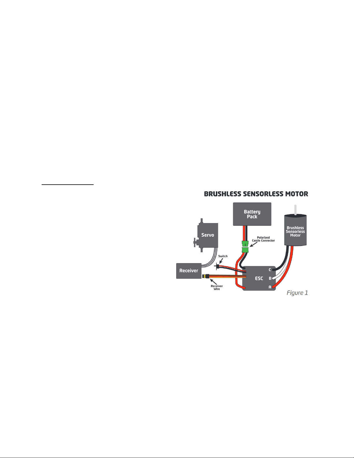
Brushless Motor Wiring, Sensorless
Motors (Figure 1)
For sensorless brushless motor
connections, the three wires from the ESC
to the motor have no polarity. Connect the
three wires coming from the motor to the
ESC’s motor connections in any order. If
you are using a motor other than a Castle
Creations motor, you may need to either
solder the included bullet plugs to your
motor or solder the ESC wires directly to
the motor wires.
If you choose to direct solder or to shorten the motor wires, you may do so on the Castle
Creations 14XX series, 15XX series, 1717, and 2028 motors only. DO NOT CUT any part of
the wire length from any other motor, regardless of brand or type. In most cases, only the
last 1/4 inch or so of the motor wires are able to be soldered. If they are clipped shorter
you may not be able to solder the remaining portion of the wire and the motor will not
run properly, if at all.
Page 5
Copperhead 10 Online Drivers Ed Guide .docx
Castle Creations 2021 ©
If the motor is supplied with connectors you
do not want to use, simply unsolder the
original motor connectors from the wires do not cut them off.
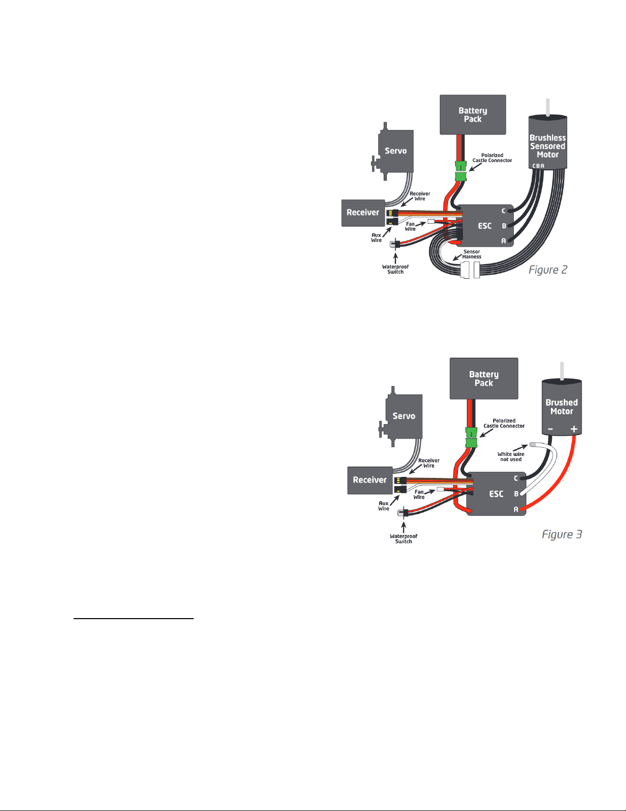
Brushless Motor Wiring, Sensored Motors*
(Figure 2):
For sensored brushless motor connections, the
three wires from the ESC to the motor DO HAVE
polarity. Connect the ESC to the motor. Connect
A to A, B to B, C to C, and install the sensor
harness after removing the dust cover. In order
to change the motor direction, use Castle Link, manually programming or B-Link Adapter.
Brushed Motor Wiring, Reversing (Figure 3)
Use this mode if you wish to use reverse. Make
sure you change the Motor Type setting to
“Brushed Reversing” in the ESC before using a
brushed motor. Connect the motor wires to the
two outside motor bullet connectors. In most
applications, the red wire from the ESC will
connect to the red wire (or positive + side hood)
of the motor, and the black wire to the black wire
(or negative - side hood) of the motor. The
middle bullet connector on the ESC is not used.
After calibration (See “How to Calibrate the
ESC”), you may need to swap the two motor
wires to get the wheels to spin in the right direction.
Radio Connection
RX Wire (Orange/Red/Brown)
Your Castle ESC RX wire plugs into the throttle channel of your receiver. This is usually
channel 2. Your Castle ESC provides power to the receiver and the steering servo. No
separate receiver battery is needed to power the radio system. Some servos can draw
Page 6

Copperhead 10 Online Drivers Ed Guide .docx
Castle Creations 2021 ©
more current than the on-board BEC can handle and will require an external BEC or
receiver pack.
Castle ESC receiver plugs are designed to work with any current receiver, but you will
need to make sure the polarity is correct when connected to the receiver. The ESC signal
wire is orange or white, the positive wire is red, and the negative wire is brown. Check
your receiver documentation for correct connection polarity if it’s not marked.
Most receivers use negative (brown) towards the outside of the case and signal
(orange/white) towards the channel markings on the case.
Individual transmitter signals for neutral, full throttle, and full brake vary. You must
calibrate your Castle ESC so that it will operate effectively with your transmitter. Anytime
the ESC is powered up with a new transmitter or with different throttle channel settings,
it will need to be calibrated to the transmitter’s throttle settings. The ESC may also need
to be calibrated after updating to new software via Castle Link.
If you are using a Futaba-made transmitter, you will need to set the transmitter’s throttle
channel direction to the REVERSE (Rev) position. This is either an external micro switch on
the transmitter or an option available within the computer programming of the
transmitter. Please start by zeroing out any throttle trim that you may have set in your
transmitter.
How to Calibrate The ESC
Safety First! Remove the pinion prior to calibration.
Step 1: Start with the transmitter ON, the battery disconnected, and the ESC switch in the
OFF position.
Step 2: Plug a battery into the ESC. If your ESC does not have a switch, hold full throttle
on your transmitter before plugging in the battery.
Step 3: Hold full throttle on the transmitter and turn the ESC switch ON. Keep holding
full throttle on the transmitter. If all your connections are correct, you will hear one multitoned initialization “ring” from the motor (all sounds are played by the ESC vibrating the
motor).
Page 7

Copperhead 10 Online Drivers Ed Guide .docx
Castle Creations 2021 ©
Step 4: If the ESC’s voltage cutoff is set to Auto-LiPo (the default setting), then the ESC
will emit a sequence of beeps indicating the number of battery cells.
If the number of beeps does NOT match the number of cells, disconnect the battery and
confirm that it is fully charged.
Step 5: After the beeps, the green LED on the ESC will blink rapidly. If the red LED is
blinking instead, reverse your throttle channel. After a couple of seconds, the motor will
“ring” four times in a row. Next, the ESC will rapidly blink the red LED and the motor will
beep continuously. At this point, the full throttle endpoint has been set within the ESC
and now it’s looking for the full brake endpoint (red LED blinking).
STEP 6: Move the throttle trigger to the full brake position and hold full brake. After a
few seconds, the motor will “ring” four times rapidly. The ESC will then blink the yellow
LED and the motor will beep continuously. At this point, the full brake endpoint has been
set within the ESC and now it’s looking for the neutral endpoint (yellow LED blinking).
STEP 7: Now relax the trigger to the neutral position. The ESC will now “ring” four times
and flash the yellow LED rapidly to accept the neutral position.
After accepting the neutral position, the ESC will “ring” twice, flash all the LEDs, and the
yellow LED will illuminate. This is the arming tone and LED indication that the ESC IS
NOW ARMED and the vehicle will respond to throttle inputs from your transmitter.
From this point on, when you connect batteries and turn the switch on, the ESC will give
the initialization “ring” followed by battery cell count beeps (only in Auto-LiPo mode),
and then after the arming delay the ESC will “ring” twice, indicating it is ARMED and will
respond to throttle application.
If you have problems calibrating your transmitter with the Castle ESC, please see the
troubleshooting guide at the end of this manual, visit our www.castlecreations.com/FAQ,
or contact our world class technical support department via email or on the phone.
Page 8

Copperhead 10 Online Drivers Ed Guide .docx
Castle Creations 2021 ©
Final Check
Once you are calibrated and armed, do one last check before going out and experiencing
the Castle brushless difference. Slowly advance the throttle and check the rotation
direction of the motor and the color of the LEDs on the ESC. If the motor is spinning in
the right direction and the green LED is blinking, then you are ready for a test run. If the
ESC shows the green LED with throttle, but the wheels spin in the wrong direction, you’ll
need to change the motor direction. See the “Motor Wiring” section.
Closely monitor your ESC and motor temperatures during the first run to ensure they stay
within the safe operating limits.
Audible Alerts
The Copperhead ESC will provide you with audible alerts that notify you of various issues
and error conditions to help you diagnose problems in your setup. These alerts only occur
when the vehicle is stopped and the ESC is in neutral. They repeat every five seconds until
the ESC’s power is cycled.
Your ESC will emit a single beep every ten seconds to let you know the ESC is
powered. This is NOT an error condition. This is simply a reminder to disconnect
the battery.
If you wish to silence these features, they can be disabled using Castle Link. See “Disable
Idle Beeps” and “Disable Error Beeps” on the “Basic” tab in Castle Link.
The audible alerts consist of a sequence of long and short beeps, repeating every five
seconds. To determine the cause of the alert, record • for short beeps and - for long
beeps, then match the code you heard to the following list.
The red LED will always blink, even if silenced.
• • Start Fail
The ESC was unable to start the motor. Check your motor wiring and make sure there is
nothing interfering with your drive train.
Page 9

Copperhead 10 Online Drivers Ed Guide .docx
Castle Creations 2021 ©
• – Low Voltage Cutoff
Main battery voltage dropped below the cutoff value. The default is Auto-LiPo which
sets the cutoff value based on the detected cell count. Other options may be entered in
Castle Link.
• • • Sensors Lost*
The ESC detected unusual signals or loss of signal on the sensor cable coming from the
motor. Check the sensor cable for good connections to the ESC and motor. If you are
not using a sensored motor, ensure the motor type is not set to “Sensored Only” in
Castle Link.
• • – Radio Glitch
The ESC detected unusual signals or loss of signal on the throttle wire.
• – • Over-Temperature
The ESC reached an over-temperature condition. Occurs when operated under too high
a load or operated without proper cooling airflow.
– • – BEC Over-Temperature*
The ESC detected that the integrated BEC is overheating due to current draw above the
rating of the BEC. This is commonly caused by faulty servos or a servo that exceeds the
amp rating of the BEC. (e.g. digital servos with very high torque/speed values)
• • • • Datalog Full Warning
The ESC’s internal datalog has reached its capacity. The datalog must be cleared before
it can record any new data.
– – • Motor Over-Temperature*
The ESC detected that the sensored motor’s temperature has exceeded the Motor
Temperature Cutoff value set in Castle Link. Motor temperature sensors vary. Always
Page 10

Copperhead 10 Online Drivers Ed Guide .docx
Castle Creations 2021 ©
check motor temperatures periodically after making system adjustments. *Only available
when running sensored motors with sensor wire connected.
Data Logging Lite
Your Copperhead ESC is able to measure and record important power system information
during your race, turn-by-turn. After your run, you can download and analyze this log
using Castle Link. You will be able to inspect many parameters including battery voltage,
motor RPM, ESC temperature, motor temperature, and ripple voltage.
Recording Duration
The ESC writes the recorded data to a limited amount of memory. Recording time varies
with the parameters selected and the sample rate. The ESC compresses data wherever
possible; periods at idle or constant throttle do not take very much memory. Use Castle
Link to select or deselect parameters logged by the ESC.
Automatic Data Reset
At power up, Automatic Data Reset checks the amount of memory used. If that value is
more than the programmed limit, the controller will erase the entire data log. This ensures
that the last few runs are saved to memory and available for analysis. The ESC will emit a
long beep tone after the arming “rings” to alert you that the data log was erased.
Manual Data Reset
Recorded data can be erased manually by holding your transmitter at full reverse when
powering up the ESC. The motor will emit the normal power up chimes. Leave throttle at
full reverse for six seconds and the motor will emit a long beep tone. The ESC will then
erase the entire data log. Return the throttle to neutral and the ESC will arm.
Tuning with Castle Link™
All Castle ESCs may be connected to your PC using the Castle Link USB adapter. The Castle
Link software will give you access to a whole new world of tuning options. You may use
Castle Link to tune your throttle and brake curves, set your drag brake feel, and use the
incredible Torque Limit to keep the front end of your car on the ground with all the power
you have at your command. As new software becomes available, you can install it in your
Page 11

Copperhead 10 Online Drivers Ed Guide .docx
Castle Creations 2021 ©
Castle ESC for new and updated features. All of this ensures your Castle ESC will be the
best that it can be.
Using Castle Link
Disconnect the RX (Orange/Red/Brown) wire from your receiver and connect it to the
Castle Link USB adapter. Castle ESCs may also be programmed using your transmitter and
receiver (see “Transmitter Programming”), or a Field Link Programming Card (see “Field
Link Programming Card”).
Castle Link Quick Connect
Experienced modelers go to great lengths to tie down their servo and throttle leads - and
some find that unplugging a Castle controller from the receiver disrupts all their work.
The Castle Link Quick Connect allows you to connect the Castle Link USB adapter without
removing wires from your receiver. Visit www.castlecreations.com/quickconnect to
purchase online.
Castle B-Link Bluetooth Adapter
The Castle B-Link Bluetooth Adapters allows you access of the settings available via the
Castle Link; with the convenience of accessing right from your Apple iOS or Android
device.
Field LINK™ Programming Card
You can use a Field Link programming card to easily change many settings at the field
without your PC, or it will function as a Castle Link adapter when you do have a PC
available. For more information visit www.castlecreations.com/fieldlink.
Transmitter Programming
Transmitter programming is very easy; simply answer YES or NO to a list of options. These
are grouped into six settings and each setting has several possible options. You can only
accept one option per setting. By answering YES to an option, you will jump to the next
setting. If you answer NO to an option, you will move to the next option within that
setting.
At each option, you can accept it by going to full throttle on your transmitter, or you can
reject the option by going to full brake. In programming terms, full throttle is ‘YES’ and
Page 12

Copperhead 10 Online Drivers Ed Guide .docx
Castle Creations 2021 ©
full brake is ‘NO.’ The ESC will indicate that it has accepted your selection by producing a
continuous “skipping” tone. When you hear this tone, allow the trigger to go back to the
neutral position to advance to the next setting or option depending on your selection.
How to Get into Programming Mode:
• Turn your transmitter on.
• Plug the battery into the ESC with its switch off.
• Hold full throttle on your transmitter and turn the ESC switch on.
• The ESC will go through its boot-up sequence and blink the green LED. If the ESC’s
voltage cutoff is set to Auto-LiPo (the default setting), then the ESC will emit a
sequence of beeps indicating the number of battery cells.
If the number of beeps does NOT match the number of cells, disconnect the
battery and confirm that it is fully charged.
• There will be a sequence of four “rings” and the red LED will blink.
• Keep holding the trigger, within 6 – 8 seconds there will be a sequence of four “rings”
and the yellow LED will blink.
• You are now in programming mode; let the trigger return to neutral.
Note: Before attempting to manually program the ESC it must be calibrated to your radio.
See the “How to Calibrate the ESC” for more details.
To Make Changes in Programming Mode:
Once in programming mode, the ESC will beep once, pause, then beep once again and
repeat until a change is made with your transmitter. For instance, if you want to adjust
setting 1 (Brake/Reverse Type) to option 1 (With Reverse) you would pull full throttle to
select it. When the trigger is returned to neutral the beep pattern will change to 2 beeps
followed by 1 beep. By selecting an option, you have now moved on to setting 2 and
option 1. If at setting 2 (Cutoff Voltage) you reject option 1 (Auto-LiPo) by going to full
brake/reverse, the beep pattern will then change to 2 beeps followed by 2 beeps. This
means the ESC is still at setting 2 but is now asking if you would like to accept option 2
(None).
Page 13

Copperhead 10 Online Drivers Ed Guide .docx
Castle Creations 2021 ©
Reject options unless you wish to change that specific setting. As an example, say you
want to adjust the Drag Brake to 20%. Work through the settings and options, rejecting
all options until you get to 4 beeps, meaning setting 4 (Drag Brake), followed by 3 beeps,
meaning option 3 (20%). Select this option by going to full throttle. Once you have
changed the setting you want, you can unplug power from the ESC to get out of
programming mode. You do not need to finish all the settings. The ESC will store your
changes until you change them again.
The next section of the manual gives a description of each of the settings and options
and what to expect when you change an option from default.
There is a reference guide on the last page.
1. Brake/Reverse Type
Sets whether reverse is enabled or not, and exactly how it can be accessed.
• Option 1: With Reverse (Default)
This setting allows the use of reverse only after the ESC senses the vehicle has
come to a stop. Use it for race practice sessions and bashing, but check with your
race director to see if this setting is allowed for actual racing.
• Option 2: Without Reverse
Reverse cannot be accessed under any circumstances with this setting. Use this
setting for sanctioned racing events that do not allow reverse driving.
• Option 3: Crawler Reverse
Reverse or forward is accessible at any time, even if the vehicle is still moving.
2. Cutoff Voltage
Sets the voltage at which the ESC stops the motor in order to protect the battery from
over-discharge.
Option 1: Auto-LiPo (Default)
This setting automatically detects the number of LiPo cells you have plugged in. It will
automatically set the cutoff to 3.2 volts per cell detected. The ESC will beep the number
Page 14

Copperhead 10 Online Drivers Ed Guide .docx
Castle Creations 2021 ©
of cells detected between the initialization “ring” and the arming “rings” on initial power
up of the ESC.
If the number of cells indicated does not match the number of cells in your LiPo
pack, do not operate the vehicle. Unplug your battery and ensure that it is fully
charged.
Check with your battery manufacturer to make sure 3.2V per cell is their
recommended cutoff. You can change this value in Castle Link if a higher per cell
voltage is needed.
Option 2: None
This setting disables low voltage cutoff.
Do not use this setting with any Lithium pack! Use this setting ONLY with NiCad or
NiMH packs.
3. Brake Amount
Sets what percentage of available braking power is applied with full brake.
Option 1: 25% Power Option 3: 75% Power
Option 2: 50% Power (Default) Option 4: 100% Power
4. Drag Brake
Sets the amount of brake applied at neutral throttle for a slight braking effect while
coasting.
Option 1: Drag Brake Disabled (Default)
Vehicle will coast with minimal resistance from the motor at neutral throttle.
Option 2: Drag Brake 10%
Low amount of braking effect from the motor at neutral throttle.
Option 3: Drag Brake 20%
Moderate braking effect from the motor at neutral throttle.
Option 4: Drag Brake 30%
High braking effect from the motor at neutral throttle.
Option 5: Crawler Full On
This setting applies full brake at neutral throttle to prevent crawler-type
vehicles from rolling or coasting when stopping on an incline.
Page 15

Copperhead 10 Online Drivers Ed Guide .docx
Castle Creations 2021 ©
5. Motor Type
Sets which type of motor you will use with the Castle ESC. The ESC may be damaged if
this setting does not match the motor type/hook-up method in the car, and this
damage is NOT covered under warranty.
Option 1: Brushless (Default)
See Brushless Motor Setup, figure 1
Option 2: Brushed Reversing
See Reversing Brushed Motor Setup, figure 3
6. Motor Direction
Allows you to change the motor direction.
Option 1: Normal (Default)
Option 2: Reverse
Troubleshooting
If you’re still having difficulties with your Castle ESC after trying the suggestions offered
here, please contact Castle Creations technical support at the email or phone number
listed in the next section.
Problem: My Castle ESC may or may not arm, but it will not calibrate to my
transmitter.
Solution: Most calibration issues can be solved by changing settings on the transmitter.
Make sure you have both your throttle and brake endpoints (called EPA or ATV on your
radio) on the throttle channel set to between 100 to 120%. If you have a Futaba-made
transmitter, make sure to have the throttle channel set to the reversed position. See “How
to Calibrate the ESC”.
Problem: My ESC calibrates for the full throttle and full brake positions but won’t
calibrate to the neutral throttle position (yellow LED keeps flashing with single
beeps).
Page 16

Copperhead 10 Online Drivers Ed Guide .docx
Castle Creations 2021 ©
Solution: Try moving the throttle trim one way, then the other. If your transmitter has a
50/50 and 70/30 setting for the throttle, set it for 50/50 and retry calibration. If you have
changed the throttle dead band to a narrower band using Castle Link, you may want to
try going back to the “normal” setting.
If you have changed the motor type to “Sensored only” using Castle Link and the
ESC is not beeping, the yellow flashing light at neutral is normal and the ESC is
ready for use.
Problem: My vehicle acts like it has “turbo lag” (poor acceleration/punch for the
first few feet or yards, and then it “kicks in”).
Solution: Make sure you’re using high quality batteries and a battery connector capable
of high amp flow (60+ amps). Ensure connector is properly sized for your application. This
behavior is very typical of a battery pack that is having difficulty providing the power your
system requires for top performance. Refer to “A Word about batteries” section for
recommended battery capacity and C ratings for use with Castle ESCs.
For NiCad/NiMH packs, use copper bars to connect cells rather than welded tabs.
Problem: My battery pack is plugged into the ESC and nothing is working - no
steering and no throttle.
Solution: Make sure the ESC’s RX wire is plugged into channel 2 on the receiver, and that
it’s plugged in with the correct orientation. Double check your solder connections on the
battery plug, and make sure the battery is charged.
For more troubleshooting tips visit www.castlecreations.com/FAQ
Warranty Info
Your Castle ESC is warranted for one (1) year from date of purchase to be free from
manufacturing and component defects. This warranty does not cover damages caused to
your motor or controller from abuse. Abuse includes, but is not limited to, incorrect
wiring, over-voltage, overloading, improper gearing, improper motor selection, incorrect
controller settings, insufficient batteries or inadequate connectors.
Page 17

Copperhead 10 Online Drivers Ed Guide .docx
Castle Creations 2021 ©
If you have any questions, comments, or wish to return your Castle ESC for warranty or
non-warranty repair or replacement, please visit www.castlecreations.com/support before
contacting us directly.
Transmitter Programming Reference
*Default Setting
1.Brake/Reverse Type 3. Brake Amount 5. Motor Type
• With Reverse* • 25% • Brushless*
• Without Reverse • 50%* • Brushed Reversing
• Crawler Reverse • 75% • Brushed High Power
• 100%
2.Voltage Cutoff 4. Drag Brake 6. Motor Direction
• Auto-Lipo* • Disabled* Normal*
• 10% Reversing
• 20%
• 30%
• Crawler Full On
Audible Alert Reference
Start Fail
• •
Low Voltage Cutoff
• –
BEC Over-Temperature
– • –
Sensors Lost
• • •
Motor Over-Temperature
– – •
Radio Glitch
• • –
Datalog Full Warning
• • • •
Over-Temperature
• – •
Page 18

Copperhead 10 Online Drivers Ed Guide .docx
Castle Creations 2021 ©
Castle Technical support
You may contact our world-class technical support department via e-mail anytime or by
phone. Please visit Castle Creations website for technical support hours.
Website: www.castlecreations.com/support
E-mail: home.castlecreations.com/contact-support
Phone: (913) 390-6939, option #1. Mon-Fri, 9AM-4PM CST.
 Loading...