

Page 1

INSTALLATION INSTRUCTIONS
61301604805 Rev. A
®
Castle
7900
FLOOR MOUNTED
CART WASHER
Page 2

Page 3

INSTALLATION
INSTRUCTIONS
®
Castle
7900 FLOOR LOADING
CART WASHER
Getinge/Castle, Inc.
1777 East Henrietta Road
Rochester, New Yor k 14623- 31 33
Phone: (800) 950-9912 USA
Facsimile: (800) 950-2570
Page 4

INSTALLATION INSTRUCTIONS 61301604805
Rev. A (12/27/01)
Related Publication:
Operator Manual 61301604804
DESCRIPTION OF SYMBOLS AND NOTES IN MANUAL
The following symbols with related notes appear in this manual.
“Warning” notes alert the user to the possibility of personal injury.
WARNING
“Caution” notes alert the user to the possibility of damage to the equipment.
CAUTION
“Notes” alert the user to pertinent facts and conditions.
NOTE
NOTE
Castle
Copyright ©2001 by Getinge/Castle, Inc.
®
is a registered trademark.
This manual contains proprietary information of Getinge/Castle, Inc. It shall
not be reproduced in whole or in part without the written permission of
Getinge/Castle, Inc.
ii
Page 5

Section 1 Installation Requirements
GENERAL DESCRIPTION. . . . . . . . . . . . . . . . . . . . . . . . . 1–1
MODEL IDENTIFICATION. . . . . . . . . . . . . . . . . . . . . . . . . 1–2
UTILITIES AND SPECIFICATIONS. . . . . . . . . . . . . . . . . . 1–3
Electrical . . . . . . . . . . . . . . . . . . . . . . . . . . . . . . . . . . . 1–3
Hot Water. . . . . . . . . . . . . . . . . . . . . . . . . . . . . . . . . . . 1–3
Cold Water. . . . . . . . . . . . . . . . . . . . . . . . . . . . . . . . . . 1–3
Steam. . . . . . . . . . . . . . . . . . . . . . . . . . . . . . . . . . . . . . 1–3
Condensate . . . . . . . . . . . . . . . . . . . . . . . . . . . . . . . . . 1–3
Drain . . . . . . . . . . . . . . . . . . . . . . . . . . . . . . . . . . . . . . 1–3
Exhaust . . . . . . . . . . . . . . . . . . . . . . . . . . . . . . . . . . . . 1–3
Weight . . . . . . . . . . . . . . . . . . . . . . . . . . . . . . . . . . . . . 1–3
Overall Size . . . . . . . . . . . . . . . . . . . . . . . . . . . . . . . . . 1–3
INSTALLATION ADVISORY . . . . . . . . . . . . . . . . . . . . . . . 1–4
WASHER OPTIONS. . . . . . . . . . . . . . . . . . . . . . . . . . . . . . 1–4
Floor Mount vs. Pit Mount . . . . . . . . . . . . . . . . . . . . . . 1–4
Left Side vs. Right Side Controls. . . . . . . . . . . . . . . . . 1–4
Barrier Flanges and Service Enclosure . . . . . . . . . . . . 1–4
Electrical Service . . . . . . . . . . . . . . . . . . . . . . . . . . . . . 1–4
Printer . . . . . . . . . . . . . . . . . . . . . . . . . . . . . . . . . . . . . 1–4
Seismic Anchoring. . . . . . . . . . . . . . . . . . . . . . . . . . . . 1–4
SHIPPING CONFIGURATION. . . . . . . . . . . . . . . . . . . . . . 1–5
TOOLS AND MATERIALS REQUIRED. . . . . . . . . . . . . . . 1–6
Table of Contents
Section 2 Installation
ASSEMBLE THE WASHER STRUCTURE . . . . . . . . . . . . 2–1
Install the Base/Sump Assembly . . . . . . . . . . . . . . . . . 2–1
Assemble the Washer Panels . . . . . . . . . . . . . . . . . . . 2–5
Door Assembly. . . . . . . . . . . . . . . . . . . . . . . . . . . . . . 2–10
Trim Panels (Non-Service Side) . . . . . . . . . . . . . . . . 2–12
INSTALL COMPONENTS ON TOP OF THE WASHER . 2–13
Dryer and Condenser Assemblies. . . . . . . . . . . . . . . 2–13
Power Floor Tilt Pulley System . . . . . . . . . . . . . . . . . 2–17
Transformer and Emergency Stop Switch
Junction Box . . . . . . . . . . . . . . . . . . . . . . . . . . . . 2–19
Rear Emergency Stop Switch . . . . . . . . . . . . . . . . . . 2–20
Plumbing Mounting Brackets. . . . . . . . . . . . . . . . . . . 2–21
61301604805 iii
Page 6

INSTALL COMPONENTS ON THE OUTSIDE
OF THE WASHER. . . . . . . . . . . . . . . . . . . . . . . . . . . 2–22
Spray Manifold Drive Motor. . . . . . . . . . . . . . . . . . . . 2–23
Exhaust Elbow. . . . . . . . . . . . . . . . . . . . . . . . . . . . . . 2–25
Washer Light Assembly. . . . . . . . . . . . . . . . . . . . . . . 2–26
Front Dryer Ducts . . . . . . . . . . . . . . . . . . . . . . . . . . . 2–27
Control Box . . . . . . . . . . . . . . . . . . . . . . . . . . . . . . . . 2–29
Junction Box Assembly. . . . . . . . . . . . . . . . . . . . . . . 2–30
Dispenser Float Switch Junction Box . . . . . . . . . . . . 2–31
Front Emergency Stop Switch. . . . . . . . . . . . . . . . . . 2–32
Detergent and Rinse Aid Dispensers . . . . . . . . . . . . 2–33
Unload End Indicator Panel Box . . . . . . . . . . . . . . . . 2–34
Door Proximity Switches . . . . . . . . . . . . . . . . . . . . . . 2–35
Sump Drain Valve . . . . . . . . . . . . . . . . . . . . . . . . . . . 2–36
Return Pump . . . . . . . . . . . . . . . . . . . . . . . . . . . . . . . 2–37
Circulation Tank Assembly . . . . . . . . . . . . . . . . . . . . 2–38
Wash Pump. . . . . . . . . . . . . . . . . . . . . . . . . . . . . . . . 2–39
Tank Drain Valve, Tank Overflow, and Tank
Water Level Indicator . . . . . . . . . . . . . . . . . . . . . 2–40
Booster Heater Assembly . . . . . . . . . . . . . . . . . . . . . 2–41
Rinse Pump. . . . . . . . . . . . . . . . . . . . . . . . . . . . . . . . 2–42
PLUMBING . . . . . . . . . . . . . . . . . . . . . . . . . . . . . . . . . . . 2–43
Stainless Steel Plumbing. . . . . . . . . . . . . . . . . . . . . . 2–43
Black Iron (Steam) Plumbing. . . . . . . . . . . . . . . . . . . 2–44
Hot Water (Copper) Plumbing. . . . . . . . . . . . . . . . . . 2–44
Cold Water (Copper) Plumbing . . . . . . . . . . . . . . . . . 2–45
ELECTRICAL WIRING. . . . . . . . . . . . . . . . . . . . . . . . . . . 2–46
Objective . . . . . . . . . . . . . . . . . . . . . . . . . . . . . . . . . . 2–46
Installation . . . . . . . . . . . . . . . . . . . . . . . . . . . . . . . . . 2–46
INSTALL COMPONENTS ON THE INSIDE OF
THE WASHER. . . . . . . . . . . . . . . . . . . . . . . . . . . . . . 2–49
Rear Dryer Ducts. . . . . . . . . . . . . . . . . . . . . . . . . . . . 2–49
Drive Chain Tension Idlers and Idler Bearings . . . . . 2–51
Chain Drive Assembly. . . . . . . . . . . . . . . . . . . . . . . . 2–52
Spray Manifold Supports and Manifold Assembly. . . 2–54
Manifold Cover and Spray Guard, Manifold Guard
Tubes, Wash Cart Tubes . . . . . . . . . . . . . . . . . . 2–56
Emergency Stop Switch Cables . . . . . . . . . . . . . . . . 2–58
FINAL INSTALLATION TASKS . . . . . . . . . . . . . . . . . . . . 2–60
Final Door Assembly . . . . . . . . . . . . . . . . . . . . . . . . . 2–61
Dispenser Tubing . . . . . . . . . . . . . . . . . . . . . . . . . . . 2–62
Sanitary Barrier Flanges . . . . . . . . . . . . . . . . . . . . . . 2–64
Pit Covers (Option) . . . . . . . . . . . . . . . . . . . . . . . . . . 2–65
Service Area Enclosure (Option). . . . . . . . . . . . . . . . 2–66
Base Shrouds (Floor Mounted Option) . . . . . . . . . . . 2–67
Ramps (Floor Mounted Option). . . . . . . . . . . . . . . . . 2–68
iv
Page 7

7900 Floor Loading Cart Washer
Exhaust Connection. . . . . . . . . . . . . . . . . . . . . . . . . . 2–68
Plumbing System Connections . . . . . . . . . . . . . . . . . 2–68
Electrical Supply Connection. . . . . . . . . . . . . . . . . . . 2–69
Concluding Tasks . . . . . . . . . . . . . . . . . . . . . . . . . . . 2–69
61301604805 v
Page 8

vi
Page 9
General Description
Section 1 Installation Requirements
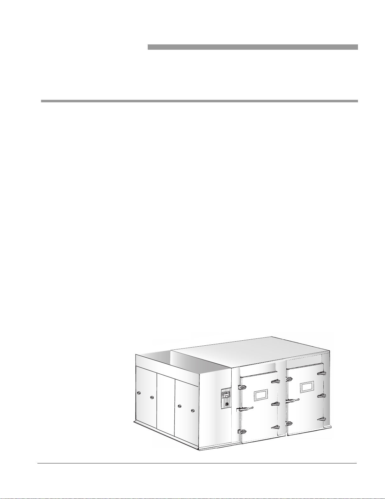
The Castle 7900 Floor Loading Cart Washer is a fully automatic, floor
loading, hydro-spray cart washer with dual side-by-side wash compartments
that is used to clean and decontaminate case carts, stands, utensils,
containers, tote boxes, and similar bulk items.
Processing cycles are set up using a programmable controller equipped
with a touch screen interface (touch control panel). Four cycle definitions
are possible. The operator needs only to select and start a cycle.
A standard cycle consists of the following sequential phases: wash, rinse,
exhaust, and drying. The length of a cycle’s phase can be adjusted at the
touch control panel.
The washer can be installed in a shallow pit or at floor level. When installed
in a pit, the floor of the washer’s chamber is level with the room floor, which
allows the direct loading and unloading of carts. When the washer is
installed at floor level, the floor is higher than the room floor. Ramps are then
provided as standard equipment to facilitate loading and unloading.
The washer is designed for pass-through operation. Items to be cleaned are
placed in the washer’s compartment through one of the load end doors.
After cleaning, the items are removed from the opposite end of the washer
through the unload end doors.
The washer is generally installed in a facility’s decontamination room with
the unload end doors opening out into a clean-preparation area. The unit is
110" (2794 mm) wide and 108" (2743 mm) high. The washer is currently
available in only one compartment size: 98" (2489 mm).
Figure 1–1. 7900 Floor Loading Cart Washer
HW-006
61301604805 1–1
Page 10
Installation Requirements
Model Identification
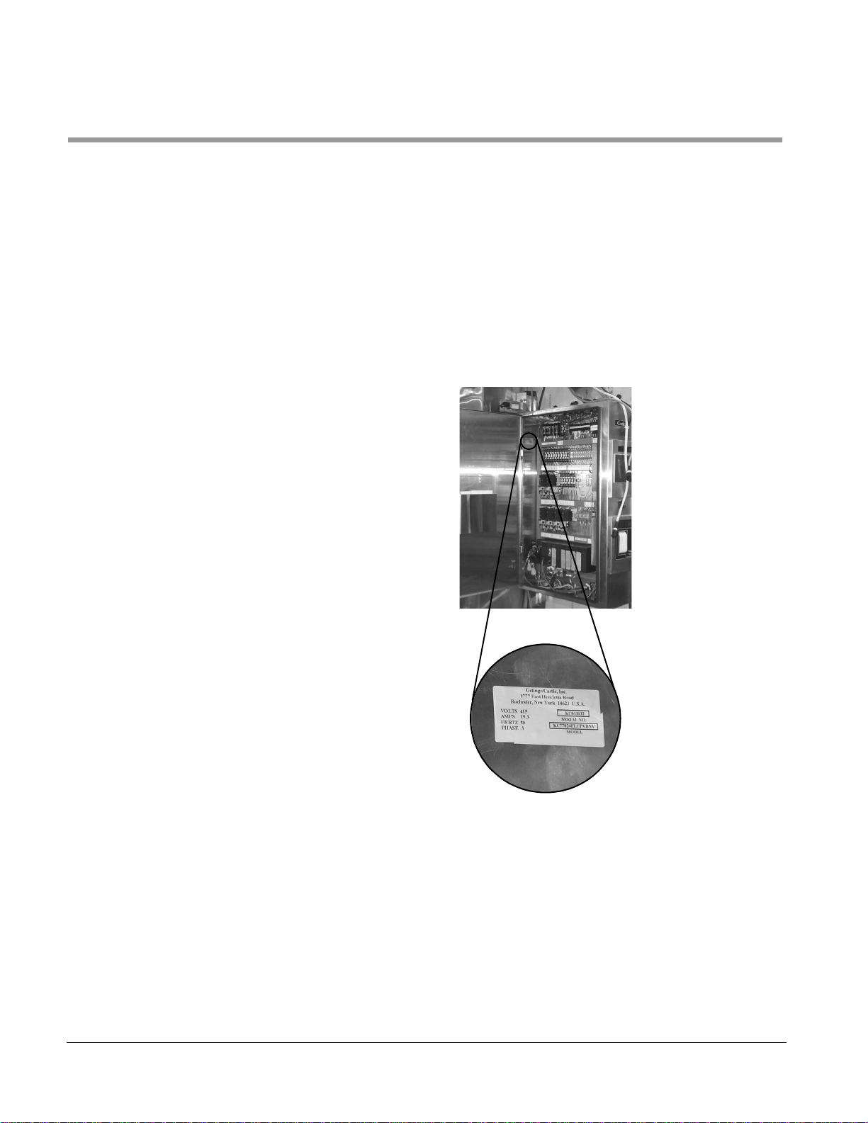
The rating plate for a 7900 washer is affixed to the inside of the control box
door.
Record the model type and serial number (S/N) from the rating plate.
TYPE: _________________________________
SERIAL NO: ____________________________
Include the model type and serial number when communicating with
Getinge/Castle.
Figure 1–2. Rating Plate Location
1–2
Page 11

Utilities and Specifications
7900 Floor Loading Cart Washer
Electrical
Hot Water
Cold Water
Steam
Condensate
208 V, 60 Hz, 3 phase, 100 A, 5-wire with neutral and ground
240 V, 60 Hz, 3 phase, 60 A, 4-wire with ground
380 V, 50 Hz, 3 phase, 60 A, 4-wire with ground
415 V, 50 Hz, 3 phase, 60 A, 4 wire with ground
480 V, 60 Hz, 3 phase, 30 A, 4-wire with ground
600 V, 60 Hz, 3 phase, 30 A, 4-wire with ground
1" IPS (25.4 mm)
40–60 PSI (276–414 kPa)
780 gal/hr (2953 l/hr) demand rate
12 gal/cycle (47 l/cycle) consumption
120° F min. (49° C)
3/4" IPS (19 mm)
40–60 PSI (276–414 kPa)
600 gal/hr (2271 l/hr) demand rate
10 gal/cycle (38 l/cycle) consumption
1-1/2" IPS
40–50 PSI (276–345 kPa)
1200 lb/hr demand rate
85 lb/cycle consumption
3/4" IPS (19 mm)
Drain
Exhaust
Weight
Overall Size
3" IPS (76. 1 mm) minimum
45 gal/cycle (170 l/cycle)
12" square flanged (304.8 mm)
3
/hr (22.7 m3/hr)
800 ft
1/4" static pressure
1800–2200 lb (811–991 kg) approximate
108" high x 110" wide x 106" long (2743 mm x 1321 mm x 1829 mm)
61301604805 1–3
Page 12

Installation Requirements
Installation Advisor y
A 7900 washer is assembled at the factory, tested, then disassembled for
shipment. Extensive on-site reassembly is required. The installation
instructions in this manual are intended as the primary reference for
accomplishing this reassembly. Every effort has been made to make this
information as accurate as possible. No two washers are exactly alike,
however.
Each washer is uniquely configured to meet the demands of its operational
site. These demands most often necessitate variances in the location of a
washer's exterior components. These variances, in turn, impact the
configuration of related plumbing and electrical wiring assemblies.
For this reason, some instructions or illustrations carried here may not
reflect the actual location or configuration of selected component
assemblies for a specific site. Where applicable, installers should refer to
specifications contained in the product information documents, such as
Rough-In and Assembly drawings, that have been forwarded to local
Getinge/Castle product support personnel.
Wa sher Options
Floor Mount vs. Pit Mount
Left Side vs. Right Side
Controls
Barrier Flanges and Service
Enclosure
Electrical Service
Printer
There are a number of options that may be included with your washer.
These options affect the procedures that apply to your specific installation.
A floor mounted washer will require the installation of ramps to provide
access to the washer. The two options may have different plumbing
specifications.
The location of controls on your washer will also determine the location of
the service area, as well as the barriers flanges and service enclosure that
may be provided with your washer.
Your installation may have barrier walls at the load or unload end of the
washer, or both, as well as have a service enclosure. These structures will
be designed specifically for your site.
The electrical service at your facility determines the specific high voltage
devices (motors, pumps, etc.), transformer, and control box provided with
your washer.
If your washer has the printer option, the printer will already be mounted on
the control box.
Seismic Anchoring
1–4
Washers with the seismic anchoring option have base/sump assemblies
that are mounted differently.
Page 13

Shipping Configuration
7900 Floor Loading Cart Washer
A disassembled 7900 washer is shipped on 4 to 8 pallets of various lengths.
The maximum size of any one pallet may be as large as 10' x 5'
(approximate). For stability during transit, selected pallets are often pegged
(with nails) to the floor of the truck.
Moving the disassembled washer from the truck to the installation site
requires the use of any available combination of the following:
• fork lift
• pallet jack
• dollies
• Johnson bars
A sufficient supply of commonly used fasteners (#10-32 and 1/4-20, for
example) is bagged for shipment. Speciality hardware and fasteners (door
latches and hinges, for example) are labeled and bagged separately for
shipment.
Many disassembled items, such as plumbing and panel sections, are
marked with handwritten numbers with black grease pen to identify their
location, orientation, or connection points. Take care not to inadvertently
smudge or erase these identifying marks.
61301604805 1–5
Page 14

Installation Requirements
Tools and Materials Required
The following tables list the specific tools and materials required at the
installation site. Items marked with an asterisk * are supplied by Getinge/
Castle.
Table 1–1. Tools Required
Tool Quantity
Common hand tools Assorted
Bar clamp 2
C-clamp 2
Johnson bar 1
Pry/pinch bar 2
Caulking gun 1
1/4-20 tap, short 1
1/4-20 tap, long 1
10-32 tap, short 1
10-32 tap, long 1
#7 drill bit 2
#21 drill bit 2
Torpedo level 1
4’ level 1
Scratch awl 2
Table 1–2. Materials Required
Material Quantity
* Silicone adhesive 8 tubes
* Silicone primer 1 pt
* Thinner 1 pt
* Polish 1 container
* Stainless steel nuts, bolts,
washers, lock washers
Assorted
1–6
* Wire nuts, ti e wraps Assorted
* 3" x 6" stainless steel shims:
• 12 ga
• 14 ga
• 16 ga
• 18 ga
12
12
12
12
Page 15

7900 Floor Loading Cart Washer
Material Quantity
1" x 4" x 6" wood block 2
2" x 4" x 52" wood block 4
The following items are recommended for use if a floor mounted washer is
to be assembled out-of-position, then moved to its intended operational site:
* 4’ x 8’ x 1/8" Masonite, smooth 2 to 3
Pipe, rigid 3/4" x 60" L 4
The Masonite protects the floor during assembly . The pipe is used to roll the
washer into position after assembly.
61301604805 1–7
Page 16

Installation Requirements
1–8
Page 17

Assemble the Washer Structure
This section contains procedures for assembling the basic structure of the
washer compartment. Refer to the following sections.
• “Install the Base/Sump Assembly” on page 2-1
• “Assemble the Washer Panels” on page 2-5
• “Door Assembly” on page 2-10
• “Trim Panels (Non-Service Side)” on page 2-12
Section 2 Installation
Install the Base/Sump
Assembly
NOTE
WARNING
General Instruction
The base/sump assembly is shipped in two halves that you must assemble
on the site. If the load or unload ends of the base are not marked, check the
configuration of the base’s sump against the rough-in drawing to determine
the correct orientation.
Some installation sites may have an existing wall in close proximity to the
non-service side of the washer that could interfere with the assembly of the
washer's side panels. If this situation exists, you will have to seat the base
temporarily out-of-position until the side, top, and non-service side trim
panels are assembled. You can then maneuver the unit to its operating
position, where you can level and anchor it, if required.
Installation
Silicone primer (orange) is extremely flammable, harmful if
swallowed or inhaled, and harmful to eyes or skin. Wear
protective clothing, gloves, and eye wear when using this
product. Keep it away from heat, sparks, and flames. Store
upright in a cool place (less than 30°C (85°F). Keep the
container closed when not in use. Use only in a well-ventilated
area. Avoid breathing vapors.
Silicone Primer stains/discolors clothing, stainless steel surfaces, flooring,
CAUTION
etc. Avoid accidental spills. Avoid spreading this substance onto exterior
surfaces of the washer.
61301604805 2–1
Page 18
Installation
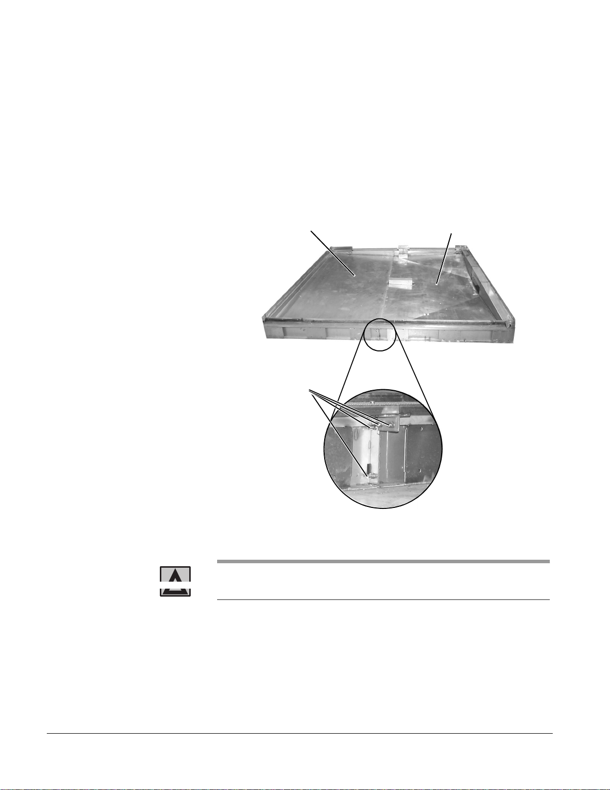
1/4-20 FASTENERS
(4 PLACES EACH END)
REAR BASE HALF
FRONT BASE HALF
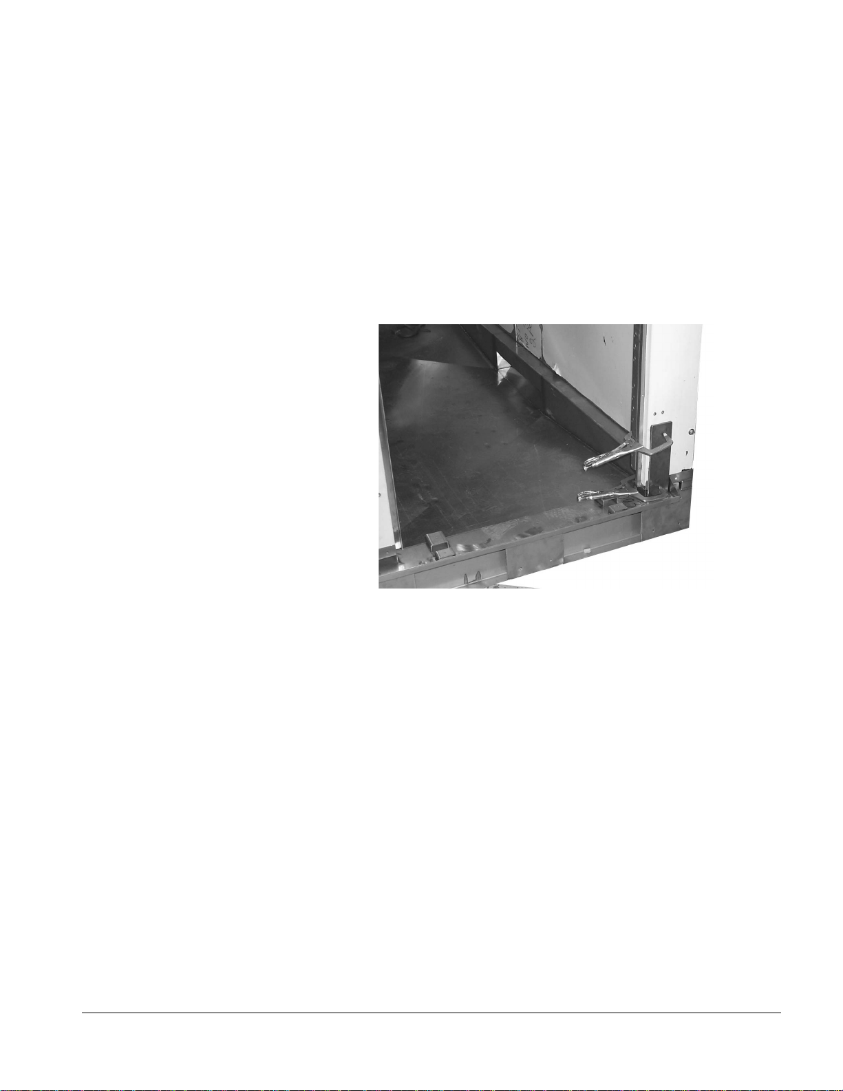
1. Clean all mating surf aces w here the tw o ha lv es of the base
meet with thinner, treat with silicone primer, and then apply
a generous amount of silicone sealant.
2. Move the two halves of the washer base together and
attach the halves together:
a. At each end , secure the front and rear halves together
with 1/4-20 fastene r s (four each 1/2" hex head bolts
and lock washers) as shown in Figure 2–1.
Figure 2–1. Attaching Ends of Base Assembly
2–2
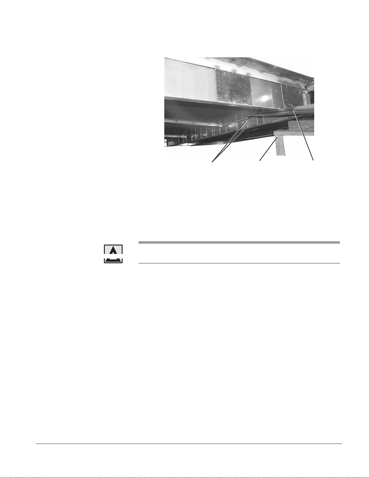
WARNING
b. Use a fork lift to raise one end of the as sembly.
Make sure that the base/sump assembly is properly supported
and secured before getting underneath the assembly.
c. Underneath the sump, secure the halv es to ge the r wi th
5/16-18 fasteners (1-1/2" hex head bolts and lock
washers), two each at six places, as shown in Figure
2–2.
Page 19
7900 Floor Loading Cart Washer
5/16-18 FASTENERS
(2 EACH AT 6 PLACES)
WOOD SUPPORT
FORK LIFT
Figure 2–2. Attaching Base Assembly Underneath
3. Move the base assembly into its final operating position.
4. Check the base for level.
Use the 4' level to check from all sides of the base and in
all directions. Adjust the level if necessary using the
stainless steel shims that are provided.
CAUTION
Failure to critically level the base will result in the misalignment of mounting
holes and will make assembly of the washer panels difficult.
If seismic anchoring is required, a 3" flange (with anchor bolt holes) is
welded to the bottom frame of the base for this purpose.
5. Drill holes for the anchors through the holes in the base
flanges.
Table 2–1. Drilling Specifications
Drill Bit Size
Embedment
Torque 50 ft.-lb.
1/2
1 1/4
"
to 3 1/2
"
"
6. Secure the base to the floor using the 1/2 x 4-1/2" stud
anchor bolts provided.
61301604805 2–3
Page 20
Installation
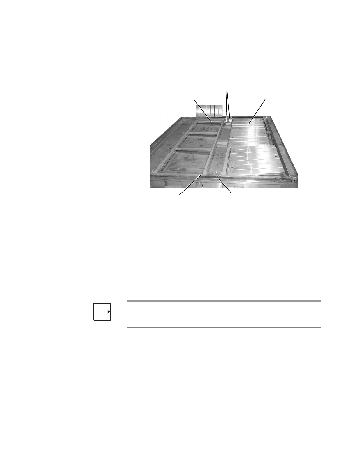
FLOOR LIFT WELDMENTS
TRACK/FR AME ASSEMBLY
FLOOR GRATES (6)
CHANNEL FILLERS
THRESHOLD ASSEM BLI ES
(2 PLACES AT EACH END)
(2 PLACES AT EACH END)
7. Lay the two track/frame assemblies into the base so that
the floor lift weldments are to wa rd the center of the w asher ,
as shown in Figure 2–3. Base/Sump Components
Figure 2–3. Base/Sump Components
8. Lay the six floor grates in the tracks into the track/frame
9. Lay the masoni te sheets over the floor grates to protect
10. Position the four channel fillers (two on each end of the
11. Install the four threshold assemblies in the floor.
NOTE
There are two sizes: the longer threshold is installed on the rear (nonservice side) of the washer, one on each end. The shorter threshold is
installed on the front (service side) of each end.
assemblies.
from scratches while you complete the installation.
washer) in the floor and secure each with two #10 -32 x 3/8"
phillips head screws.
a. Position one threshold assembly in its appropriate
location with the gasket facing toward the inside of the
washer.
b. Secure the assembly to the washer base with two #10-
32 x 3/8" phillips head screws.
2–4
Page 21

7900 Floor Loading Cart Washer
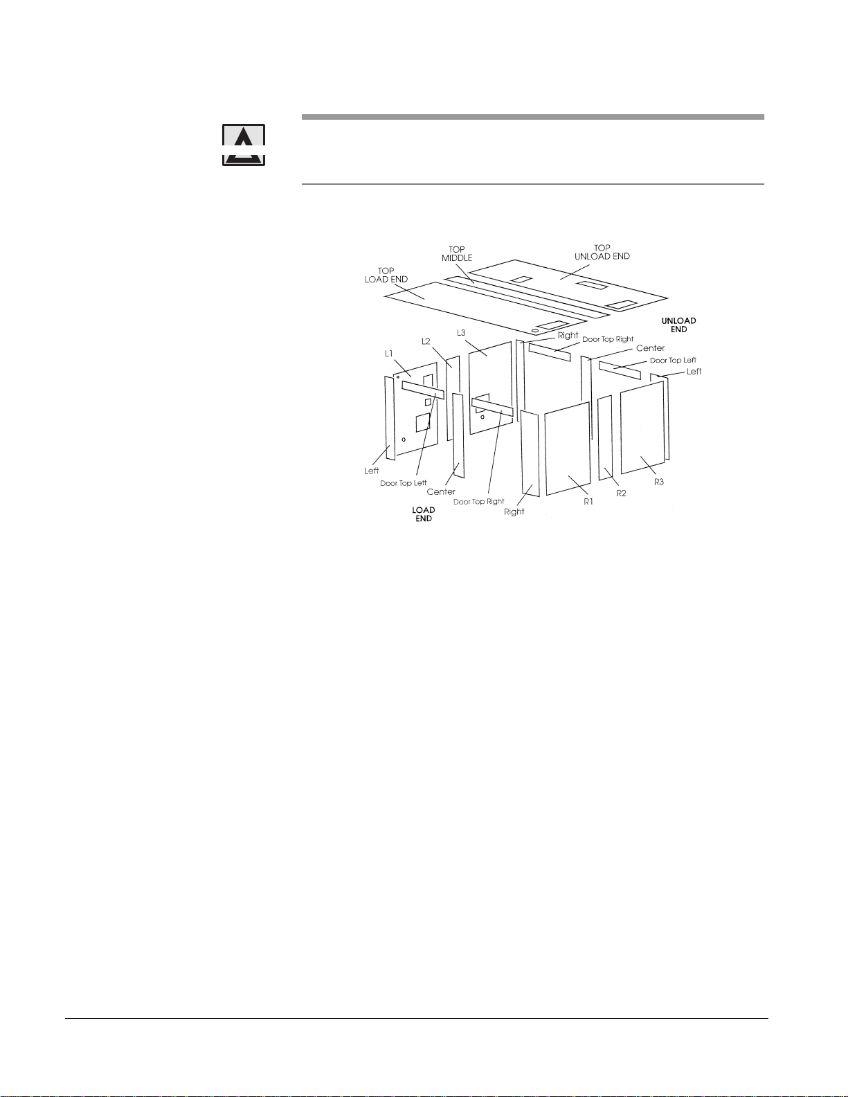
Assemble the Washer Panels
Objective
Assemble the door, side, and top panels. Install the required number of
interior side panel seam cover strips and the center mounting bracket.
There are six side panels and three top panels. Each of the end (door)
panels in turn consists of five panels: three vertical panels and two
horizontal panels (one over each door) that connect to the vertical panels.
Door panels and side panels are marked to indicate their location. Top
panels are not marked (check this). The unload end top panel has two
rectangular cutouts for the condenser mountings, a cutout for one of the rear
dryer ducts, and numerous threaded holes on its exterior surface for
mounting the dryer assemblies. The load end top panel one cutout for the
second rear dryer duct and has fewer mounting holes (for a transformer and
plumbing mounting plates). the middle panel has mounting brackets for the
floor tilt actuators. The width of a top panel is the width of the washer (92").
The side panels have 7/16" diameter holes that carry 3/8" thru bolts (five on
each side of the washer) to hold the panels together. The top panels have
holes to carry five thru bolts.
There is no established order to follow for panel assembly. You can start
from the load or the unload end. You can assemble all the vertical panels
first, followed by the top panels; or you can add individual top panels as you
erect the vertical panels. The method illustrated below starts from the load
end and progressively adds top panels as the vertical panels are erected.
NOTE
WARNING
You must clean all mating surfaces with thinner, then treat with silicone
primer, and then apply a generous amount of silicone sealant.
Installation
Refer to Figure 2–4. Assembling the Washer Panels for help to identifying
washer panels.
You must clean all mating surfaces with thinner, then treat with silicone
primer, and then apply a generous amount of silicone sealant.
Silicone primer (orange) is extremely flammable, harmful if
swallowed or in haled, and harmful to eyes or skin. Wear
protective clothing, gloves, and eye wear when using this
product. Keep it away from heat, sparks, and flames. Store
upright in a cool place (less than 30°C (85°F). Keep the
container closed when not in use. Use only in a well-ventilated
area. Avoid breathing vapors.
61301604805 2–5
Page 22
Installation
CAUTION
Silicone Primer stains/discolors clothing, stainless steel surfaces, flooring,
etc. Avoid accidental spills. Avoid spreading this substance onto exterior
surfaces of the washer.
Figure 2–4. Assembling the Washer Panels
1. Clean all mating surfaces with thinner, treat with silicone
primer, and then apply a generous bead of silicone sealant
wherever a wall panel is atta ched to the base or to ano the r
panel.
2. Attach the load end door panels to the base.
There are three vertical panels. The service side panel is
narrow and has thr ee mounting holes at the top to a ttach to
the horizontal panels. The middle panel is narrow and has
six mounting holes at the top. The non-service-side panel
is wide.
a. Position a vertic al panel.
b. Secure the bottom legs of the panel to the base frame
with 1/4-20 fasteners (1/2" hex head bolts, flat
washers, and lock washers).
c. Repeat steps a and b for the other vertical panels.
d. Secure each horizontal panel between two vertical
panels with 1/4-20 fasteners (six each 3/4" hex head
bolts and lock washers).
2–6
Page 23
7900 Floor Loading Cart Washer
3. Attach the load end sid e panels to the bas e and to the l oad
end door.
a. Position one of the load end side panels.
b. Partially insert five 3/8" diameter thru rods through the
7/16" diameter holes to stabilize and align the side
panel with the door panel.
c. Use pipe clamps to draw the panels tight as shown in
Figure 2–5.
Figure 2–5. Installin g Washer Panels
d. Secure the bottoms o f the side p anel to the ba se frame
with 1/4-20 fasteners (1/2" hex head bolts and lock
washers).
e. Repeat steps a through d for the other load end side
panel.
4. Attach the middle side panels to the base and to the load
end panels.
a. Remove the pipe clamps.
b. Position one of the middle side panels.
c. Extend the five thru bolts to stabilize and align the
panels with the load end side panel.
d. Attach the pipe clamps to draw these pan els tight.
e. Secure the bottoms of the middle Side panel to the
base frame with 1/ 4-20 fasteners (1/2" hex head bolts
and lock washers).
61301604805 2–7
Page 24

Installation
f. Repeat steps a through d for the other middle side
panel.
g. To ensure side panel alignment, attach C-clamps and
2x4" wooden blocks across the top edge of the
adjoining panels at the vertical seam.
5. Attach the load end top panel to the door panel and to the
load end side panels.
a. Position the load end top panel.
b. Secure the top panel to the door and load end side
panels with 1/4- 20 fast eners (1-3/4" hex hea d bolts, fl at
washers, and lock washers).
c. Partially i nsert the five remaining 3/8" diameter thru
bolts through the 7/16" diameter holes in the panel.
6. Attach the unload end side panels to the base and to the
middle (or load end) side panels.
a. Remove the pipe clamps.
b. Position one of the unload end side panels.
c. Extend the five thru bolts to stabilize and align this
panels with the previously erected panels.
d. Attach the pipe clamps to draw these panels tight.
e. Secure the bottom of the unload end side panel to the
base frame with 1/ 4-20 fasteners (1/2" hex head bolts
and lock washers).
f. Repeat steps a throug h d f or th e other u nload end si de
panel.
g. Move the C-clamp and 2" x 4" wooden block
assemblies to the vertical seams created by the
installation of t hese panels.
7. Attach the middle top panel to the load end top panel and
to the middle side panels.
a. Position the middle top panel.
b. Extend the two thru bolts.
c. Secure this panel to the mid dle side panel s with 1/4-20
fasteners ( 1-3/4" hex head bolts, flat washer s, an d loc k
washers).
2–8
Page 25

7900 Floor Loading Cart Washer
8. Attach the unload end door panels to the base and to the
unload end side panels.
a. Remove the pipe clamps.
b. Position a vertical panel.
c. Secure the bottom legs of the panel to the base frame
with 1/4-20 fasteners (1/2" hex head bolts, flat
washers, and lock washers).
d. Repeat st eps a and b for the other vertical panels.
e. Secure each horizontal panel between two vertical
panels with 1/4-20 fasteners (six each 3/4" hex head
bolts and lock washers).
f. Extend the ten side thru bolts.
g. Attach the pipe clamps to draw the door panels tight.
h. Secure the thru bolts at both ends of the washer with
3/8" acorn nuts and flat washers.
9. Attach the unload end top panel to the unload end side
panels and to the unload end door panel.
a. Remove the C-clamp assemblies.
b. Position the unload end top panel.
c. Extend the five thru bolts.
d. Secure this panel to the unload end door panels and
side panels with 1/4-20 fasteners (1-3/4" hex head
bolts, flat washers, and lock washers).
e. Secure the thru bolts at both ends of the washer with
3/8" acorn nuts and flat washers.
10. Inside the washer, attach the four panel seam cover strips
over the vertical seams between adjoining side panels
using #10-32 screws and lock washers.
11. Attach the center mounting plate inside the washer, from
the load end to the unload end.
a. Align the holes in the mounting plate with the threaded
holes along the center of the washer.
b. Secure the mounting plate to the washer with six 1/4-
20 fasten ers ( 3/ 4" hex head cap screws, lock washers,
and flat washers). The mounting plate is attached to
the top panels in four places and once in each center
end panel.
61301604805 2–9
Page 26
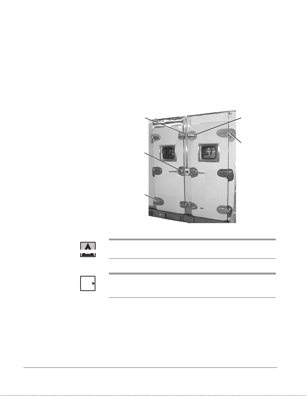
Installation
HINGE MOUNT
DOOR HINGE
(3 PER DOOR)
DOOR LATCH
RETAINERS
(2 PER DOOR)
DOOR HANDLE
DOOR LATCH
(2 PER DOOR)
(3 PER DOOR)
Door Assembly
Objective
Attach hardware to the doors and related door panels. Install two doors
each on both the load and unload ends of the washer. Plumb and square all
four doors.
Installation
Refer to Figure 2–52. Door Assembly.
Figure 2–6. Door Ass embly
2–10
WARNING
NOTE
A washer door is heavy and awkward to handle. Take care to
avoid crushing or strain injuries.
The washer may be shipped with all of the hardware (hinges, latches, striker
plates, etc.) already mounted on both the doors and the door panels. If so,
start with step 3 below.
Page 27

7900 Floor Loading Cart Washer
1. Attach the following items to each door panel:
a. Attach three hinge m oun ts u s ing ni ne 1/ 4- 20 fasteners
(1" phillips head screws).
b. Attach two door latch retain er s, two door latch shims,
and two spacers using four 5/16-18 fasteners (2" hex
head cap screws and lock washers).
2. Attach the following items to each door:
a. Attach two door latches using four 5/16-18 fasteners
(1" hex head cap screws and lock washers).
b. Attach three hinges using twelve 1/4-20 fasteners
(1" phillips head screws).
c. Attach the door handle using four 5/16-18 fasteners
(1" hex head cap screws and lock washers).
3. Mount the door on the washer.
a. Raise and maneuver the door until its hinge posts are
in vertical alignment over the three hinge mounts
attached to the door panel.
NOTE
b. When aligned, lower the door and properly seat al l
three posts in their respective mounts.
4. Repeat steps 1 through 3 for the other door assemblies.
5. Check all door openings for plumb and square. If
necessary, use the shims that are provided.
After the plumb and square of all doors is checked and corrected, it may be
easier to lift the doors off their hinges and set them aside until the end of the
installation of the washer.
61301604805 2–11
Page 28

Installation
Trim Panels (Non-Service
Side)
Objective
The narrow width of the trim panels and the presence of a restrictive wall
may require that you assemble the washer out-of-position up to this point.
After you attach the panels, you can move the washer to its exact
operational position, where you can level the washer, and seismically
anchor it if required.
Installation
1. Attach any required trim panels to the non-service side of
the washer using #10-32 fasteners (3/8" pan head screws
and lock washe rs).
2. If necessary, move the washer to its final position. Level
and, if required, anchor the washer.
2–12
Page 29

Install Components on Top of the Washer
There are a number of components that are installed on the top panels of
the washer. Although there is no specific order in which the components
should be installed, the list below presents the items in a recommended
order. Refer to the following sections.
•“Dryer and Condenser Assemblies” on page 2-13
•“Power Floor Tilt Pulley System” on page 2-17
•“Transformer and Emergency Stop Switch Junction Box” on page 2-19
•“Rear Emergency Stop Switch” on page 2-20
•“Plumbing Mounting Brackets” on page 2-21
Before installing any components on top of the washer, you must ensure
CAUTION
that the door openings are plumb and square. Failure to do so can result in
doors that do not open and close correctly, as well as water leaks.
7900 Floor Loading Cart Washer
Dryer and Condenser
Assemblies
Objective
Assemble the two dryer/blower assemblies, the two condenser duct
assemblies, and the rear top dryer duct.
Generally, the dryer assemblies are mounted on top of the washer. When
sufficient space is not available, these assemblies are redesigned for
installation in the unit’s service area. These configurations vary and are not
accurately represented in these Installation Instructions. To install the dryer
assemblies in the washer's service area, refer to the Rough-In Drawing for
guidance.
61301604805 2–13
Page 30

Installation
CONDENSER
HEATING COIL
DRYER/BLOWER
ASSEMBLY
UNLOAD END
FRONT SIDE
Installation
1. Install the front dryer/blower assembly and the condenser
on the washer. Refer to Figure 2–7. Front Dryer and
Condenser Assembly Locations.
Figure 2–7. Front Dryer and Condenser Assembly Locations
NOTE
a. Position the front dryer/blower assembly on top of the
unload end top panel.
The front (service side) dryer is normally located at the unload end of the
washer and oriented so that the heating coil faces the side of the washer.
b. Align the holes in the assembly’s mounting frame with
the matching #10-32 threaded holes in the panel.
c. Apply sealant to the screw threads and secure the
frame to the panel with eight #10-32 fasteners (3/4"
slotted pan head screws, lock washers, and flat
washers).
d. Apply silicone sealant to the edge of the front
condenser cut out in the top panel.
e. Position the front condenser duct assembly on the
unload end top panel.
f. Align the holes in the assembly’s flange to the
matching #10-32 threaded holes around the outside of
the opening in the panel.
g. Secure the condenser’s flange to the top panel with
eight #10-32 (3/4" phillips head screws, lock washers,
and flat washers).
h. Attach the 9" vent hose to the condenser and to the
dryer with hose clamps.
2–14
Page 31

7900 Floor Loading Cart Washer
CONDENSER
HEATING COIL
DRYER/BLOWER
ASSEMBLY
UNLOAD END
REAR SIDE
TOP DRYER DUCT
2. Install the rear dryer/blower assembly, condenser, and top
dryer duct on the washer. Refer to Figure 2–8. Rear Dryer
and Condenser Assembly Locations.
Figure 2–8. Rear Dryer and Condenser Assembly Locations
NOTE
a. Position the rear dryer/blower assembly on top of the
unload end top panel.
The rear (non-service side) dryer is normally located near the middle of the
washer and oriented so that the heating coil faces the side of the washer.
b. Align the holes in the assembly’s mounting frame with
the matching #10-32 threaded holes in the panel.
c. Apply sealant to the screw threads and secure the
frame to the panel with #10-32 fasteners (eight each
3/4" slotted pan head screws, lock washers, and flat
washers).
d. Apply silicone sealant to the edge of the front
condenser cut out in the top panel.
e. Position the front condenser duct assembly on the
unload end top panel.
f. Align the holes in the assembly’s flange to the
matching #10-32 threaded holes around the outside of
the opening in the panel.
g. Secure the condenser’s flange to the top panel with
#10-32 (eight each 3/4" phillip s head screws, lock
washers, and flat washers).
61301604805 2–15
Page 32

Installation
h. Attach the 9" vent hose to the condenser and to the
dryer with hose clamps.
i. Apply silicone sealant to the mating flange surrounding
the rear dryer’s heating coil and to the mating surfaces
surrounding the tw o 18" x 7-1 /2" re ctangu lar cuto uts in
the top pane ls.
j. Position the rear dryer duct on top of the washer.
k. Secure the duct to the heating coil flange with #10-32
fasteners (fifteen each 1/2" phillips head screws, lock
washers, and flat washers).
l. Secure the duct to the top panel with nine #10-32
fasteners per cutout (nine each 1/2" phillips head
screws, lock washers, and flat washers).
m. Inside the washer compartment, apply additional
sealant to the interior joints formed between the duct
and the panel.
3. Connect the dr ain output from each of the con de nse rs and
the elbow fitti ng located beneath each blo wer to dr ain using
3/4" diameter flexible tubing, hose clamps, and tee
connectors. Refer to Figure 2–9.
Figure 2–9. Condenser and Dryer Drain Tubing
FRONT
CONDENSER
TO
DRAIN
REAR
CONDENSER
REAR
BLOWER
TEE
CONNECTORS
FRONT
BLOWER
2–16
Page 33

7900 Floor Loading Cart Washer
ACTUATOR
1/4-20 FASTENERS
(6 PLACES)
RETRACT LIMIT SWITCH
EXTEND LIMIT SWITCH
Power Floo r Tilt Pulley
System
Objective
Install the power floor tilt pulley system. The top panels have 1/4-20
threaded holes to mount the system’s five components. The actuator
assembly is installed on the top middle panel, with the actuator mounted on
the front (service) side and the pulleys in the middle. The pulley cables run
the length of the washer from the middle to ends of the washer above the
load and unload end doors.
Installation
Figure 2–10. Power Floor Tilt Actuator Assembly
1. Install the following components on the service side of the
washer's top panels:
a. Align the actuator assembly with the holes in the top
panel and secure with six 1/4-20 fasteners. Refer to
Figure 2–10. Power Floor Tilt Actuator Assembly.
b. Secure the two lo ad end pulle y mou nts to the middle o f
the load end top panel with 1/4-20 fasteners (two each
1/2" hex he ad scre ws, loc k w ashers , and f lat w ashers).
Refer to Figure 2–11. Power Floor Tilt Pulley Mounts.
c. Secure the two unload end pulle y mounts to the middle
of the unload end top panel with 1/4-20 fasteners (two
each 1/2" hex head screws, lock washers, and flat
washers).
61301604805 2–17
Page 34

Installation
1/4-20 FASTENERS
(2 PLACES EACH)
PULLEY MOUNTS
FLOOR LIFT
WELDMENTS
CABLE
FASTENERS
Figure 2–11. Power Floor Tilt Pulley Mounts
2. Route the four pulley cables from the actuator, through the
pulley mounts, and then down through the four gasketed
cable holes in the paneling to the compartment floor.
NOTE
You may have to enlarge a gasket hole with a drill if the cable does not fit
through the hole.
3. Slide the black cable sleeves over the section of cable
inside the washer.
4. Using a cable fastener, secure each of the four pulley
cables to its corresponding floor lift weldment. Ref er to
Figure 2–12. Attaching Cables to Floor Lift Weldments.
Figure 2–12. Attaching Cables to Floor Lift Weldments
2–18
5. Using #6-32 fasteners, attach the two limit switches to the
actuator's mounting plate.
Page 35

7900 Floor Loading Cart Washer
EMERGENCY STOP SWITCH
JUNCTION BOX
TRANSFORMER
Transformer and Emergency
Stop Switch Junction Box
Objective
Install the transformer and the junction box for the emergency stop switches
to the top of the washer. The specific transformer used with your washer
depends on the house-supplied voltage.
Figure 2–13. Transformer and Emergency Stop Junction Box Locations
Installation
Refer to Figure 2–13. Transformer and Emergency Stop Junction Box
Locations.
1. Install the transformer.
Transformers are siz ed d ifferently but are gene ra lly loca ted
on the service side of the load end top panel and
positioned so that the output power cable is facing the
service side fo the washer.
1. Align the transformer’s mounting holes to the thread ed
holes in the panel.
a. Secure the transformer to the panel with four 1/4-20
fasteners.
2. Install the emergency stop switch junction box.
a. Remove the face plate of the box.
b. Align the mounting holes in the back of the bo x with the
two #10-32 threaded holes on the top panel near the
transf ormer you installed above.
c. Use #10-32 fasteners to secure the box to the washer.
d. Install the face plate.
61301604805 2–19
Page 36

Installation
EMERGENCY STOP
SWITCH
1/4-20 FASTENERS
MOUNTING BRACKET
Rear Emergency Stop Switch
Objective
Attach the rear emergency stop switch to the top of the washer. The switch
is mounted on the rear (non-service side) of the washer at the load end.
Installation
Refer to Figure 2–14. Rear Emergency Stop Switch.
Figure 2–14. Rear Emergency Stop Switch
1. Mount the emergency stop switch to the mounting bracket
using 1/4-20 fasteners (two each hex head cap screws,
lock washers, and flat washers).
2. Align the two holes in the mounting bracket with the holes
on the load end top panel.
3. Secure the bracket and switch to the washer with 1/4-20
fasteners (two each hex head cap screws, lock washers,
and flat washers).
2–20
Page 37

7900 Floor Loading Cart Washer
CONDENSATE (BI) PIPE BRACKET
RINSE (SS) PIPE BRACKET
STEAM (BI) PIPE BRACKET
WASH (SS) PIPE BRACKET
Plumbing Mounting Brackets
Objective
Attach four mounting brackets to the top of the washer to support the piping
for the rear side of the washer.
Installation
Refer to Figure 2–15. Plumbing Mounting Brackets for the location and
relative size of each bracket.
Figure 2–15. Plumbing Mounting Brackets
1. Determine the correct location for each bracket. The
brackets are marked with index markers that match
numbers on the top panel.
2. Align the holes in one mounting bracket with the two holes
in the top of the washer.
3. Secure the bracket with 1/4-20 fasteners (two each hex
head cap screws, lock washers, and flat washers).
4. Repeat st eps 2 and 3 for the other brackets.
61301604805 2–21
Page 38

Installation
Install Components on the Outside of the Washer
This section provides instructions for installing equipment on the outside of
the washer. The procedures are presented in a recommended order (some
larger components are easier to install if they are done earlier, f or example).
Refer to the following sections.
•“Spray Manifold Drive Motor” on page 2-23
•“Exhaust Elbow” on page 2-25
•“Washer Light Assembly” on page 2-26
•“Front Dryer Ducts” on page 2-27
•“Control Box” on page 2-29
•“Junction Box Assembly” on page 2-30
•“Dispenser Float Switch Junction Box” on page 2-31
•“Front Emergency Stop Switch” on page 2-32
•“Detergent and Rinse Aid Dispensers” on page 2-33
•“Unload End Indicator Panel Box” on page 2-34
•“Door Proximity Switches” on page 2-35
•“Sump Drain Valve” on page 2-36
•“Return Pump” on page 2-37
•“Circulation Tank Assembly” on page 2-38
•“Wash Pump” on page 2-39
•“Tank Drain Valve, Tank Overflow, and Tank Water Level Indicator” on
page 2-40
•“Booster Heater Assembly” on page 2-41
•“Rinse Pump” on page 2-42
2–22
Page 39

7900 Floor Loading Cart Washer
FLANGE BEARING
3/8-16 FASTENERS
(4 PLACES)
LOAD END
1/4-20 FASTENERS
(6 PLACES)
Spray Manifold Drive Motor
Objective
Assemble the spray manifold drive's flange bearing and the spray manifold
drive motor.
Installation
Figure 2–16. Manifold Drive Flange Bearing
1. Use 3/8"-16 fa sten ers (four each 1" hex head cap screws
and lock washers) to loosely secure the flange bearing in
position at the upper corner of the load end side panel, as
shown in Figure 2–16.
NOTE
You will tighten the bearing after you assemble the drive shaft and couple it
to the drive motor (refer to “Chain Drive Assembly” on page 2-52).
Figure 2–17. Spray Manifold Drive Motor
61301604805 2–23
Page 40

Installation
2. As shown in Figure 2–17, position the spray drive manifold
motor and bracket over the six threaded holes located in
the panel directly below the flange bearing and use 1/4-20
fasteners (six each 3/4" hex head cap screws, lock
washers, and flat washers) to secure the mounting fixture
to the panel.
3. Slip the proximity switch collar over the drive shaft of the
motor and secure by tightening the hex head cap screw.
2–24
Page 41

7900 Floor Loading Cart Washer
Exhaust Elbow
Objective
Install the exhaust elbow on the side of the washer.
Installation
Refer to Figure 2–18. Exhaust Elbo w.
Figure 2–18. Exhaust Elbow
1. Apply silicone sealant to the mating surface surrounding
the 12" cutout next to the spray manifold drive motor.
2. Position the exhaust elbow against the cutout and secure
with 1/4-20 faste ne rs (e ight each hex head cap screw s,
lock washers, and flat washers).
3. Inside the washer comp artment, apply additional sealant to
the interior joint formed between the elbow and the side
panel.
61301604805 2–25
Page 42

Installation
#10-32 FASTENERS
(4 PLACES)
#10-32 FASTENERS
(8 PLACES)
Washer Light Assembly
Objective
Install the interior light in the cutout located on the front (service side) wall.
Installation
1. Remove and retain the nine fasteners securing the interior
cover of the light assembly.
2. Align the holes in the light assembly with the holes
surrounding the cutout in the front panel.
3. Secure the light assembly to the front panel with four #1032 fasteners (phillips head screws and flat washers) as
shown in Figure 2–19.
Figure 2–19. Washer Light Assembly (Outside)
4. On the inside of the washer, apply silicone sealant around
the edge of the light assembly.
5. Place the gasket and cover over the light assembly and
secure with eight #10-32 fasteners (phillips he ad screws,
lock washers, and flat washers) as shown in Figure 2–20.
Figure 2–20. Washer Light Assembly (Inside)
2–26
Page 43

7900 Floor Loading Cart Washer
HORIZONTAL SECTION OF
FRONT DRYER DUCT
Front Dryer Ducts
Objective
Mount the dryer ducts.
The front (service side) dryer duct connects the dryer’s heating coil to two
13-1/4" x 18" cutouts in the side panels. Generally, the duct work consist of
a vertical and a horizontal section. However, other configurations are
possible if the dryer is mounted against the side of the unit. The rear (nonservice side) dryer duct connects to two cutouts on the top panel of the
washer, which in turn, connect to the two rear dryer ducts on the inside of
the washer.
Installation
1. Install the lower (horizontal) section of the front (service
side) dryer duct. Refer to Figure 2–21. Horizontal Section
of Front Dryer Duct.
Figure 2–21. Horizontal Section of Front Dryer Duct
a. Apply silicone sealant to the mating surfaces
surrounding the 18" x 13-1/4" rectangular cutouts in
the front (service side) side panels.
b. Secure the horizont al secti on o f the duct to the cutout s
with ten #10-32 fasteners (1/2" phillips head screw,
lock washer, and flat washer) per cutout.
c. Inside the washer compartment, apply additional
sealant to the interior joints formed between the duct
and the panel.
61301604805 2–27
Page 44

Installation
VERTICAL SECTION OF
FRONT DRYER DUCT
HORIZONTAL SECTION
STEAM HEATER
#10-32 FASTENERS
(9 PLACES)
#10-32 FASTENERS
(10 PLACES)
2. Install the upper (vertical) section of the front dryer duct.
Refer to Figure 2–21. Horizontal Section of Front Dr yer
Duct.
Figure 2–22. Vertical Section of the Front Dryer Duct
NOTE
a. Apply silicone sealant to the mating flange surrounding
the dryer’s heating coil and to the mating surface
between the vertical and horizontal ducts.
b. Position the vertical duct on the horizontal duct.
c. Secure the upper end to the heating coil flange with
#10-32 fasteners (fifteen each 1/2" phillips head
screws, lock washers, and flat washers).
d. Secure the lower end to the horizontal duct with #10-
32 fasteners (nine 1/2" phillips head screws, lock
washers, and flat washers).
One or more standoffs may have been welded to the dockworker to support
a plumbing assembly. Clamps are provided to secure plumbing to standoffs.
2–28
Page 45

7900 Floor Loading Cart Washer
1/4-20 FASTENERS
CONTROL BOX
(4 PLACES)
Control Box
Objective
Attach the control box to the load end side panel.
Installation
Refer to Figure 2–23. Control Box.
Figure 2–23. Control Box
1. Remove the pins from the door hinges and set the door
aside.
2. Position the control box on the load end side panel and
align the mounting tabs on the top and bottom of the box
with the four threaded holes in the panel.
3. Use 1/4-20 fasteners (4 each 3/4" hex head cap screws,
flat washers, and lock washers) to s ecure the control bo x to
the panel.
4. Install the door on the control box.
61301604805 2–29
Page 46

Installation
#10-32 FASTENERS
(4 PLACES)
LOWER DRYER DUCT
EXHAUST ELBOW
Juncti on B ox Assembly
Objective
Install the junction box assembly to the side of the washer.
Installation
Refer to Figure 2–24. Junction Box Assembly.
Figure 2–24. Junction Box Assembly
1. Position the junction box and align its mounting holes with
those on the front panel of the exhaust elbow and on the
top of the lower dryer duct.
2. Secure the junction box to the exhaust elbow and to the
dryer duct using #10- 3 2 fasteners (four each 3/8"pa n head
screws and lock washers).
2–30
Page 47

7900 Floor Loading Cart Washer
JUNCTION BOX
LOAD END
WASH MANIFOLD
FITTING
Dispenser Float Switch
Junction Box
Objective
Install the junction box for the detergent and rinse aid dispenser float
switches on the front (service side) panel at the load end of the washer.
Installation
Refer to Figure 2–25. Dispenser Float Switch Junction Box.
Figure 2–25. Dispenser Float Switch Junction Box
1. Remove the face plate of the box.
2. Align the mounting ho les in the bac k of the b ox wi th the two
#10-32 threaded holes on the front side panel at the load
end of the washer.
3. Use #10-32 fasteners to secure the box to the panel.
4. Install the face plate.
61301604805 2–31
Page 48

Installation
EMERGENCY STOP
SWITCH
1/4-20 FASTENERS
MOUNTING
(4 PLACES)
BRACKET
Front Emergency Stop Switch
Objective
Attach the front emergency stop switch to the side panel of the washer. The
switch is mounted at the load end of the washer, over the detergent
dispenser.
Installation
Refer to Figure 2–26. Front Emergency Stop Switch.
Figure 2–26. Front Emergency Stop Switch
1. Mount the emergency stop switch to the mounting bracket
using two 1/4-20 fasteners (hex head cap screws, lock
washers, and flat washers).
2. Align the two holes in the mounting bracket with the holes
on the load end side panel.
3. Secure the bracket and switch to the washer with two 1/420 fasteners (hex head cap screws, lock washers, and flat
washers).
2–32
Page 49

7900 Floor Loading Cart Washer
#10-32 FASTENERS
(4 PLACES)
DRYER DUCT
Detergent and Rinse Aid
Dispensers
Objective
Mount the detergent dispenser on the load end side panel (below the control
box) and the rinse aid dispenser to the top of the lower dryer duct.
Installation
Refer to Figure 2–27. Detergent Dispenser.
Figure 2–27. Detergent Dispenser
1. Remove the cover of the detergent dispenser.
2. Align the mounting holes in the back plate with the
threaded holes in the panel.
3. Use two #10-32 fasteners to secure the dispenser in place.
4. Replace the c over.
Figure 2–28. Rinse Aid Dispenser
5. Position the rinse aid pump on the top of the bottom dryer
duct (between the junction box and the top dryer duct) and
align with the holes in the duct.
6. Secure the pump mount to the top of the dryer duct with
four #10-32 fasteners (phillips head screws and lock
washers).
61301604805 2–33
Page 50

Installation
Unload End Indicator Panel
Box
Objective
Mount the indicator panel box on the unload end of the washer.
Installation
Refer to Figure 2–29. Unload End Indicator Panel Box.
Figure 2–29. Unload End Ind icator P anel Box
1. Remove the face plate of the box.
2. Align the mounting ho les in the bac k of the b ox wi th the two
#10-32 threaded holes at the edge of the unload end
barrier panel.
3. Use #10-32 fasteners to secure the box to the panel.
4. Install the face plate.
The box overhangs the panel to permit the routing of its electrical cable.
2–34
Page 51

7900 Floor Loading Cart Washer
PROXIMITY SWITCH
ASSEMBLY
Door Proximity Switches
Objective
Install a proximity switch assembly on both the load and the unload end door
panels.
Installation
Refer to Figure 2–30. Door Proximity Switches.
Figure 2–30. Door Proximity Switches
1. Orient the two ends of the switch assembly as shown in
Figure 2–30 and align with the threaded mounting holes in
the panel.
2. Use three #10-32 fasteners (phillips head screw and lock
washer) to secure the top of the assembly to the middle
panel above and between the doors.
3. Use four #10-32 fasteners (phillips head screw and lock
washer) to secure the bo ttom of the assembly to the middle
panel between the door latches.
4. Route the as sembly’s cables to the junction box on the
service side of the washer:
The load end cables, P3 and P5, connect to the junction
box at J3 and J5, respectively. The unload end cables, P4
and P6, connect to the junction box at J4 and J6,
respectively.
5. Repeat st eps 1 through 4 for the other door assembly.
61301604805 2–35
Page 52

Installation
SUMP
DRAIN VALVE
TO DRAIN
Sump Drain Valve
Objective
Install the motorized sump drain valve assembly.
Installation
Refer to Figure 2–31. Sump Drain Valve.
Figure 2–31. Sump Drain Valve
1. As shown in Figure 2–31, use a hose clamp to attach one
flexib le hose o n the dra in va lve assembly t o the 2" outl et on
the sump.
2. Use a hose clamp to atta ch the hose from the d rain v alve to
the intake on the return pump box.
3. Route the last hose to drain.
2–36
Page 53

7900 Floor Loading Cart Washer
RETURN PUMP
LOW SUCTION
COLLAR
SPLASH COVER
FRONT SUMP
5/16-18
FASTENERS
(2 PLACES)
1/4-20
FASTENERS
(2 PLACES)
COVER
Return Pump
Objective
Attach the return pump to the sump framework.
Installation
Refer to Figure 2–32. Return Pump.
Figure 2–32. Return Pump
1. Slide the low suction collar over the bottom of the return
pump and position the pump in the su mp.
2. Secure the pump to the flange on the front sump cover by
attaching the two ends of the metal strap with 5/16"-18
fasteners (2" hex head cap screws and lock washers) to
the flange.
Figure 2–33. Return Pump
3. Place the two halves of the splash cover around the pump
and secure with two 1/4-20 fasteners (1" hex head cap
screws and nuts).
61301604805 2–37
Page 54

Installation
ADJUSTABLE LEGS
(4 PLACES)
BOLTS
(6 PLACES)
TANK
TANK BASE
Circul ati on Tank Assembly
Objective
Assemble, position, and level the circulation tank.
Installation
Refer to Figure 2–34. Circulation Tank.
Figure 2–34. Circulation Tank
1. Refer to the rough-in drawing and position the tank base at
the correct location.
2. Use the adjustabl e le gs to level the tank.
3. Place the tank on the base so that th e drain flange fits
through the hole in the base and the small holes fit o ve r the
anchoring bolts in the base.
4. Secure the tank to the base with six fasteners (nuts, flat
washers, and lock washers).
2–38
Page 55

7900 Floor Loading Cart Washer
FASTENERS
(4 PLACES)
CIRCULATION TANK
BOTTOM SHELF
W a sh Pum p
Objective
Install the wash pump in the bottom shelf of the tank.
Installation
Refer to Figure 2–35. Wash Pump.
Figure 2–35. Wash Pump
1. Place the pump on the bottom rack of the circulation tank
assembly and align the ho les in the pump with the bolts in
the mounting plate.
2. Secure the pump to the tank with four fasteners (lock
washers, flat washers, and nuts).
61301604805 2–39
Page 56

Installation
DRAIN PIPE
DRAIN VALVE
TO DRAIN
FROM TANK
TO DRAIN
OVE RFLOW FITTI NG
WATER L EVEL
INDICATOR FITTINGS
Tank Drain Valve, Tank
Overflow, and Tank Water
Level Indicator
Objective
Install the motorized tank drain valve assembly, the tank overflow drain, and
the tank water level indicator.
Installation
Figure 2–36. Tank Drain Valve
1. As shown in Figure 2–36, use a hose clamp to attach one
flexible hose to the drain valve assembly and to the 2"
outlet on the wash pump.
2. Use a hose clamp to atta ch the hose from the d rain v alve to
drain.
3. As shown in Figure 2–36, secure the flexible drain hose to
the tank with a hose clamp. Use additional hose to rout e
the overflow to drain.
Figure 2–37. Tank Overflow Drain and Water Level Indicator
2–40
4. Secure the transparent indicator hose to the top and
bottom fittings with hose clamps.
Page 57

7900 Floor Loading Cart Washer
1/4-20 FASTENERS
(4 PLACES)
CIRCULATION TANK
BOTTOM SHELF
Booster Heater Assembly
Objective
Install the booster heater assembly.
Installation
Refer to Figure 2–38. Booster Heater Assembly.
Figure 2–38. Booster Heater Assembly
1. Position the booster heater assembly in the bottom shelf of
the circulation tank and align with the holes in the shelf.
2. Secure the assemb ly to the tank with 1/4-20 f a steners (f our
each 3/4" hex head cap screws, flat washer s , and lo ck
washers).
61301604805 2–41
Page 58

Installation
1/4-20 FASTENERS
(4 PLACES)
CIRCULATION TANK
WASH PUMP
BOTTOM SHELF
RINSE PUMP
Rinse Pump
Objective
Install the rinse pump on the bottom rack of the circulation tank.
Installation
Refer to Figure 2–39. Rinse Pump.
Figure 2–39. Rinse Pump
1. Position the pump on the bottom shelf of the circulation
tank and align with the holes in the bottom of the shelf.
2. Secure the pump to the tank with fasteners (four each hex
head cap screws, lock washers, and flat washers).
2–42
Page 59

Plumbing
7900 Floor Loading Cart Washer
The washer plumbing is designed with a large number of quick-disconnect
joints that enable service personnel to isolate problems and to replace
components easily. When a washer is disassembled at the factory for
shipment to a customer, plumbing sections are removed for efficient packing
and quick assembly at the installation site. All plumbing sections are tagged
at both ends to indicate what the section is connected to. The following
information provides only general descriptions of the completed plumbing.
For details of the plumbing for your site, refer to the drawings provided with
your washer and to the information tagged to each plumbing section.
Stainless Steel Plumbing
Objective
Install the washer’s stainless steel tubing.
Installation
Refer to Figure 2–40. Typical Stainless Steel Plumbing Connector.
Figure 2–40. T ypical Stainless Steel Plumbing Connector
The stainless steel plumbing for the washer consists of the following
sections:
• Return pump to the intake of the circulation tank.
• The circulation tank drain to the wash pump and to the tank drain valve.
• The wash pump to two 2-1/2" sanitary fittings on the front wall, and over
the top of the washer to a 2-1/2" sanitary fitting on the rear of the load
end top panel.
• The inside front wall to the two front wash manifold hoses.
• The inside rear wall to the rear wash manifold hoses.
• The copper fitting near the output of the booster heater two 1-1/4"
sanitary fittings on the front wall, and over the top of the washer to a 11/4" sanitary fitting on the rear of the load end top panel.
• The inside front wall to the two front rinse manifold hoses.
• The inside rear wall to the two rinse manifold hoses.
61301604805 2–43
Page 60

Installation
Black Iron (Steam) Plumbing
Hot Water (Copper)
Plumbing
Objective
Install the steam supply line and the condensate return line.
Installation
The black iron steam plumbing for the washer consists of the following
sections:
• The utility connection to the booster heater, to the circulation tank, and
over the top of the washer to the two dryer heaters.
• Condensate from the dryer heaters to the booster heater and the
circulation tank.
Objective
Install the hot water supply line.
Installation
The copper plumbing for hot water consists of the following sections:
• The utility connection to the intake for the circulation tank and to the
intake of the rinse pump.
• The rinse pump to the booster heater.
• The booster heater to a stainless steel fitting on the front side of the
washer.
2–44
Page 61

7900 Floor Loading Cart Washer
DRAIN HOSE
TANK HOT WATER
FILL PIPE
Cold Water (Copper)
Plumbing
Objective
Install the cold water supply line.
Installation
The copper plumbing for cold water consists of the following sections:
• The utility connection up over the top of the washer to the two
condensers on the unload end top panel.
• The condensers to a connect flexible drain hose, which then connects to
the fitting at the fill pipe of the tank, as shown in Figure 2–41. Secure the
flexible drain hose with hose clamps.
Figure 2–41. Dryer Heater Condensate Feed to Tank
61301604805 2–45
Page 62

Installation
Electrical Wiring
Objective
Make all required electrical wire connections between the electrical
components and the control box and junction boxes.
Installation
1. Route all component electrical cables, including
thermocouple cables, from the control box or junction box
to the appropriate elect rical component.
Refer to Table 2–2 and Table 2–3 for the routings.
2. Connect the cables to the corresponding electrical
component.
Most cables have keyed connectors that plug in and are secured with
threaded fittings. Cables that must be wired to the component are noted in
Table 2–2 and Table 2–3.
NOTE
Attach all solenoid coil housings to their related solenoid valve bodies, as
shown in Figure 2–42.
Figure 2–42. Solenoid Valve Assembly
The actual configuration for your washer may vary from that listed here.
2–46
Page 63

7900 Floor Loading Cart Washer
Table 2–2. Junction Box Cable Connections
Jack Cable P/N Cable Label Destination
J2 61301603973 P1 – P2 Control Box Jack J1
J3 Y960788 P3 – 1PS Load End Proximity Switch
1PS
J4 Y960788 P4 – 2PS Unload End Proximity Switch
2PS
J5 Y960788 P5 – 3PS Load End Proximity Switch
3PS
J6 Y960788 P6 – 4PS Unload End Proximity Switch
4PS
J7 61301603975 P7 – 1LS Retract Limit Switch 1LS
J8 61301603975 P8 – 2LS Extend Limit Switch 2LS
J9 61301603976 P9 –2MV Tank Drain Valve 2MV
J10 61301603988 P10 – 7MTR Exhaust Elbow Damper 7MTR
J11 61301603978 P11 – 6MTR Front Condenser Damper
6MTR
J12 61301603978 P12 – 8MTR Rear Condenser Damper
8MTR
J13 Y960456 P13 – 3SOL Tank Hot Water Solenoid
Valve 3SOL
J14 Y960456 P14 – 4SOL Tank Steam Solenoid Valve
4SOL
J15 Y960456 P15 – 5SOL Booster Heater Steam Sole-
noid Valve 5SOL
J16 Y960456 P16 – 1SOL Front Dryer Steam Solenoid
Valve 1SOL
J17 Y960456 P17 – 8SOL Rear Dryer Steam Solenoid
Valve 8SOL
J18 Y960456 P18 – 2SOL Front Condenser Cold Water
Solenoid Valve 2SOL
J19 Y960456 P19 –9SOL Rear Condenser Cold Water
Solenoid Valve 9SOL
J20 Not used.
J21 Not used.
J22 61301603980 P22 – P22A Unload End Indicator Box
J23 61301603981 P23 – 9MTR Detergent Pump 9MTR
J24 (part of rinse
aid dispenser)
J25 61301603982 P25 – 1E/2E Circulation Tank High and Lo w
J26 61301603983 P26 – 1ACT Floor Tilt Actuator 1ACT
J27 61301603984 P27 – 1DS Washer Compartment Light
J28 Not used.
J29 Not used.
J30 Not used.
P24 – 10MTR Rinse Aid Pump 10MTR
Water Level and Refresh
Probes
1DS
61301604805 2–47
Page 64

Installation
Table 2–3. Control Box Cable Connections
Jack Cable P/N Cable Label Destination
J1 61301603973 P1 – P2 Junction Box Jack J2
J31 61301603985 P31 – 1TC Circulation Tank Thermocou-
ple 1TC
J32 61301603985 P32 – 2TC Front Dryer Thermocouple
2TC
J33 61301603985 P33 – 3TC Rear Dryer Thermocouple
3TC
J34 61301603985 P34 – 4TC Rinse Water Thermocouple
4TC
J35 Not used.
J36 61301604134 P36 – 1MTR Wash Pump 1MTR
J37 61301603987 P37 – 2MTR Front Dryer Blower 2MTR
J38 61301603987 P38 – 3MTR Rear Dryer Blower 3MTR
J39 61301603988 P39 – 4MTR Manifold Drive Motor 4MTR
J40 61301603989 P40 – TTransformer T
J50 61301603976 P50 – 1MV Sump Drain Valve
J51 P51 – JB2 Dispenser Float Switch Junc-
tion Box
J53 P53 – 3S Emergency Off Switch 3S
J55 P55 – 11SOL Rinse Hot Water Solenoid
Valve 11SOL
J58 P58 – 14 MTR Return Pump 14 MTR
J59 P59 – 5PS Manifold Drive Motor Monitor
(Proximity Switch)
J60 P60 – 15 MTR Rinse Pump 15MTR
2–48
Page 65

Install Components on the Inside of the Washer
REAR DRYER
DUCTS
MOUNTING PLATE
This section provides instructions for installing equipment on the inside of
the washer. The procedures are presented in a recommended order. Refer
to the following sections.
•“Rear Dryer Ducts” on page 2-49
•“Drive Chain Tension Idlers and Idler Bearings” on page 2-51
•“Chain Drive Assembly” on page 2-52
•“Spray Manifold Supports and Manifold Assembly” on page 2-54
•“Manifold Cover and Spray Guard, Manifold Guard Tubes, Wash Cart
Tubes” on page 2-56
•“Emergency Stop Switch Cables” on page 2-58
7900 Floor Loading Cart Washer
Rear Dryer Ducts
Objective
Attach the two rear interior ducts to the rear wall of the washer and to the
cutouts in the ceiling. Attach the mounting plate between the dryer ducts.
Installation
Figure 2–43. Interior Dryer Ducts
1. Inside the washer, apply silicone sealant to the two 18" x 7-
1/2" rectangular cutouts in the top of the washer
compartment.
61301604805 2–49
Page 66

Installation
2. Position one of the dryer ducts on the wall and align the
mounting holes with those in the compartment wall and
ceiling.
3. Secure the duct to the wall with eight #10-32 fasteners
(1/2" phillips head screws, lock washers, and flat washers).
4. Secure the duct to the ce iling cutouts with nine #10-32
fasteners per cutout (1/2" phillips head screws, lock
washers, and flat washers).
5. Repeat steps 2 through 4 for the o ther duct.
6. Install the mounting plate between the two dryer ducts.
Secure to the dryer ducts and to the top panel with seven
#10-32 fasteners.
2–50
Page 67

7900 Floor Loading Cart Washer
Drive Chain Tension Idlers
and Idler Bearings
Objective
Install the following components inside the washer compartment:
• Four drive chain tension idlers
• Two idler bearings
Installation
Refer to Figure 2–44. Drive Chain Idler and Idler Bearing.
Figure 2–44. Drive Chain Idler and Idler Bearing
1. Mount the f our driv e cha in tension i dlers , one on eith er side
of the compartment and two in the middle. The front drive
chain tension id ler is atta ched to the w asher pan el, the re ar
idler is attached to the moun ti ng bracket between the two
dryer ducts, and the middle idlers are attached to either
side of the center mounting bracket.
Secure each with four 1/4-20 fasteners (3/4" hex head cap
screw and lock washer).
2. Mount the two idler bearings for the manifold drive shaft at
the load end of the rear side panel and of the front side of
the center mounting bracket. Secure each with three 1/420 fasteners (1" hex head cap screw, loc k n ut, loc k w asher,
and flat washer).
61301604805 2–51
Page 68

Installation
Chain Drive Assembly
Objective
Install the drive shaft, drive chains, and push rod that comprise the chain
drive assembly.
Installation
Refer to Figure 2–45. Chain Driv e Assem bly.
Figure 2–45. Chain Drive Assembly
2–52
1. Insert the drive shaft key into the keyway in the spray
manif old drive motor that you in sta ll e d previously.
2. Mount the front drive shaft seal to the inside of the upper
corner of the load end side panel, opposite the flange
bearing that you installed previously.
a. Position the seal so its rubber side is against the panel.
b. Secure in place with #10-32 fasteners (3/8" pan head
screw and lock washer).
3. Insert, but do not fasten, the motor and idler ends of each
shaft assembly into the shaft coupling.
4. Hang the two push rod/chain ass emblies from the shaft
assembly.
5. Fit the idler end into the idler bearing that you installed
previously.
Page 69

7900 Floor Loading Cart Washer
6. Extend the moto r e nd through the seal a nd fl an ge bearing,
and then engage the key (installed in step 1) with the
shaft’s keyway.
7. Rotate the idler end of the shaft until its sprocket key is in
alignment with the sprocket key at the shaft's motor end.
8. Secure the shaft ends to the sha ft coupling with two #10-32
bolts and jam nuts.
9. Adjust the proximity switch so that the gap between the
switch an d the se nsin g colla r on the driv e sh af t is less t han
or equal to 2 mm.
10. Use #10-32 f asteners (f ou r each 1/4" pan head scre ws and
lock washers) to attach the drive coupling guard to the
motor’s mounting fixture.
NOTE
You can wait until the operation of the motor has been checked by Product
Support personnel before installing the drive coupling guard.
11. Insert the ends of the push rod chain assembly into the
push rod sleeve.
12. Fit the chains onto their r ela ted sprockets at the driv e sha ft
and at the drive chain tension idlers that you installed
previously.
Make sure the ends of the push rod ar e seated on
matching sprocket teeth.
13. Adjust the chain tensi on so there is no more tha n 1" of pla y
in either line.
You can loosen a tension idler’s 3/8-16 bolt to permit
move m ent of it s sprocket. Turning the 1/4-20 adjustmen t
bolt repositions the sprocket, thereby increasing or
decreasing chain tension.
14. Repeat steps 2 through 11 for the rear chain drive
assembly.
61301604805 2–53
Page 70

Installation
Spra y Manifold Supp orts and
Manifold Assembly
Objective
Install the three spray manifold supports, one on either side of the washer
compartment and one in the middle, and then install the two spray manifold
assemblies.
Installation
Refer to Figure 2–46. Spray Manifold Support.
Figure 2–46. Spray Manifold Support
2–54
1. Seat the ends of the outside ( front and rear ) spra y manif old
supports in the uppermost captive brac k ets that are welde d
to the inside of the end panels.
2. Apply silicone se alant to f our #10- 32 fa steners, t hen secure
the mounting angle of the front support to the front side
panel.
3. Use four #1 0- 32 fasteners to secure the moun ti ng ang le of
the rear support to the mounting plate between the two
dryer ducts.
4. Attach 1/4-20 fasteners to the captive brackets to ensure
the ends of the spray manifold supports remain in place.
Page 71

Figure 2–47. Spray Manifold Assembly
7900 Floor Loading Cart Washer
5. Attach two rinse an d tw o w ash hose conn ectors to th e inl et
port s in the front side panel. Repeat for the rear panel.
When tight, all c onnectors should point toward the unload
end of the unit at an angle of approximately 45 degrees.
6. Set the two spray manifolds on the manifold supports.
7. Seat the ends of the middle spray manifold support in the
uppermost captive br ack ets that ar e welded to the in side of
the end panels.
8. Attach 1/4-20 fasteners to the captive brackets to ensure
the ends of the spray manifold supports remain in place.
9. Connect the manif olds at th e top with tw o stringer s in each
compartment. Orient the stringers so that their push pins
are directed toward the load end. Use 5/16-18 fastener s to
secure the stringers to the manifolds.
10. Use 5/16-18 fasteners to connect the manifolds at the
bottom (one on e ach side and one in th e middle ) with three
connector bars. Use two sets of fasteners at each end of
each connector bar.
11. Install the wash a nd rinse ho ses betw ee n the ma nifold and
the panel hose connect or s . Secure each end of each hose
with two hose clamps. Position the hoses so they rest
against the panels and not obstruct manifold movement.
61301604805 2–55
Page 72

Installation
Manifold Cover and Spray
Guard, Manifold Guard
Tubes, Wash Cart Tubes
Objective
Install the following components inside the washer:
• Two manifold covers
• Manifold spray guard
• Four manifold guard tubes
• Three wash cart guide tubes
Installation
Refer to Figure 2–48. Manifold Cover and Spray Guard, Manifold Guard
Tubes, Wash Cart Guide Tubes.
Figure 2–48. Manifold Cover and Spray Guard, Manifold Guard Tubes,
Wash Cart Guide Tubes
2–56
1. Position a manifold cover on top of each side of the spray
manifolds. Secure the cover in place at the load and unload
ends with eight #10-32 fasteners (two at each end of each
cover).
2. On the front side of the w ash er, position the manifold spray
guard against the inside of the spray manifolds so that the
cutouts fit over the manifold nozzles. Secure the guard in
place at the load and unload ends with six #10-32
fasteners.
Page 73

7900 Floor Loading Cart Washer
3. Attach the ten manif old gu ard tubes to the brac k ets w elded
to the load and unload end door panels. For each wash
compartment, attach three tubes to the outer side and two
tubes on the side at the middle of the washer.
a. Place a 1/4-20 bolt through the manifold guard tube
brackets on each end of the washer at the appropriate
level and secure with a locknut.
b. Insert each end of the manifold guard tube so that it
rests on the bolt inside the bracket.
NOTE
There are two manifold guard tubes that each have three eyebolts to
accommodate the emergency stop cables. These tubes should be installed
as the middle of the three tubes that are installed on the outer sides of the
washer. These tubes are also secured to the bracket through holes in the
tube, rather than by resting on the bolt.
4. Install the six wash cart guide tubes, three on each outer
side of the washer.
a. Position three wash cart guid e tubes on the outside
edge of the front wash compartment.
b. Butt the edges of the tube’s mounting brac kets against
the floor frame over the sump.
c. Using the brackets as templates, drill and tap four 1/4-
20 holes into the grate. Make sure the holes are
located against the inside of the bracket slots so the
tube can to be adjusted back toward the center line of
the floor.
d. Repeat steps a through c f or three remaining w ash cart
guide tubes on the outside edge of t he re ar w ash
compartment.
e. Secure all six tubes to the floor with 1/4-20 fasteners.
61301604805 2–57
Page 74

Installation
EMERGENCY
STOP CABLE
CABLE CONNECTOR
LOAD END
EYE BOLT
EMERGENCY
STOP CABLE
FRONT
WELDMENTS
Emergency Stop Switch
Cables
Objective
Install the emergency stop cables. One cable runs along each side of the
washer. The front cable passes through the side panel and connects to the
emergency stop switch on the service side of the washer. The rear cable
passes through the top panel and connects to the switch mounted on top of
the washer.
Installation
1. Install the emergency stop cable on the front side of the
washer and connect to the switch on the outside of the
washer.
a. Refer to Figu re 2–49. At the unload end of the washer,
attach one en d of the cable to the guide rail bracket.
Loop the cable through the next hole in the bracket
above the guide rail and secure with a cable fastener.
Figure 2–49. Emergency Cable Connection
2–58
b. As shown in Figure 2–50, feed the cable through the
three ey ebolt s on the gui de rail to the load e nd, aroun d
the two we ldments o n the fron t side panel , and throu gh
the opening in the front side panel.
Figure 2–50. Front Emergency Stop Cable
Page 75

7900 Floor Loading Cart Washer
LOAD END
EYE BOLT
EMERGENCY
STOP CABLE
REAR
WELDMENT
c. Secure the end of the cable to the emergency stop
switch assembly with a cable fastener as shown in
Figure 2–26.
2. Install the emergency stop cable on the rear side of the
washer and connect to the switch on the top of the washer.
a. Refer to Figu re 2–49. At the unloa d end of the wa she r,
attach one en d of the cable to the guide rail bracket.
Loop the cable through the next hole in the bracket
above the guide rail and secure with a cable fastener.
b. As shown in Figure 2–51, feed the cable through the
three ey ebolt s on the gui de rail to the load e nd, aroun d
the weldment on the end panel, and up through the
opening in the rear side top panel.
Figure 2–51. Rear Emergency Stop Cable
c. Secure the end of the cable to the emergency stop
switch assembly with a cable fastener as shown in
Figure 2–14.
61301604805 2–59
Page 76

Installation
Final Installation Tasks
This section provides instructions for completing the installation of the
washer. Refer to the following sections.
•“Final Door Assembly” on page 2-61
•“Dispenser Tubing” on page 2-62
•“Sanitary Barrier Flanges” on page 2-64
•“Pit Covers (Option)” on page 2-65
•“Service Ar ea En cl osur e (Opti on) ” on page 2-66
•“Base Shrouds (Floor Mounted Option)” on page 2-67
•“Ramps (Floor Mounted Option)” on page 2-68
•“Exhaust Connection” on page 2-68
•“Plumbing System Conne ct ions” on page 2-68
•“Electrical Supply Connection” on page 2-69
•“Concluding Tasks” on page 2-69
2–60
Page 77

7900 Floor Loading Cart Washer
Final Door Assembl y
Objective
Hang the load and unload doors back on their hinges.
Installation
Refer to Figure 2–52. Door Assembly.
Figure 2–52. Door Assem bly
A washer door is heavy and awkward to handle. Take care to
WARNING
avoid crushing or strain injuries.
1. Mount the door on the washer.
a. Raise and maneuver the door until its hinge posts are
in vertical alignment over the three hinge mounts
attached to the door panel.
b. When aligned, lower the door and properly seat al l
three posts in their respective mounts.
Repeat steps 1 through 3 for the other door assemblies.
61301604805 2–61
Page 78

Installation
TO DETERGENT SUPPLY
TO CIRCULATION TANK
Dispenser Tubing
Objective
Connect the detergent and rinse aid dispenser pump tubing.
Installation
1. Connect the detergent tubing.
a. Place the detergent float switch assembly (see
Figure 2–53) in the detergent supply container.
Figure 2–53. Detergent/Rinse Aid Float Switch
b. Connect the supply tubing from the detergent float
switch to the left side of the detergent pump (Figure 2–
54).
Figure 2–54. Detergent Pump
2–62
c. Connect the DETERGENT connector from the float
switch to the DETERGENT connector from the cable
connected to the float switch junction box.
d. Connect the discharge tubing to the right side of the
detergent pump.
e. Connect the plastic compression fitting on the other
end of the tubing to the fitting on the tank.
Page 79

7900 Floor Loading Cart Washer
TO RINSE AID SUPPLY
TO RINSE AID INJECTOR
2. Connect the rinse aid tubing.
a. Place the rinse aid float switch assembly in the rinse
aid supply container.
b. Connect the supply tubing from the fl oat switch
assembly to the bottom plastic compression fitting on
the rinse aid pump (Figure 2–55).
Figure 2–55. Rinse Aid Pump
c. Connect the RINSE AID connector from the float
switch to the RINSE AID connector from the cable
connected to the float switch junction box.
d. Connect the discharge tubing to the top fitting on the
rinse aid pump using plastic compression fitting.
e. Slide the other end of the tubing over the copper
injector fitting near the output of the booster heater.
61301604805 2–63
Page 80

Installation
Sanitary Barrier Flanges
NOTE
Objective
Attach the sanitary barrier flanges to the load and unload ends of the
washer.
The following instructions apply to units with structural walls situated at both
the load and unload ends. Units with only one wall (generally at the unload
end) receive a service area enclosure and an unload end top barrier flange.
For the latter configuration, refer to “Service Area Enclosure (Option)” on
page 2-66.
The method and materials for securing the sanitary barrier flanges to a
structural wall are to be provided by the customer.
Installation
1. Using #10-32 fasteners, attach the two short attachment
angles to the load end side panel and the single long
attachment angle to the unload end side panel. Position the
proximity switch and unload end indicator panel cables so
they route through the cutouts provided in the angles.
2. Secure the load and unload end side barrier flanges to the
attachment angles with #10-32 fasteners.
The interior edge of a flange seats between an angle and
the side panel.
3. Attach the top barrier flanges.
a. Remove and retain the acorn nut fasteners from the
two top thru bolts.
b. Attach the load and unload end top barrier flanges.
c. Use the acorn nuts along with #10-32 fasteners to
secure the flanges to the top panels and to the side
barrier flanges.
4. Attach the intake frame assembly to the unload end top
barrier flange.
2–64
Page 81

7900 Floor Loading Cart Washer
Pit Covers (Option)
Objective
Install the pit covers, if that option has been provided, at the load and unload
Ends of a pit mounted washer.
An additional pit cover may be provided for installation along the non-service
side of the washer if that side is exposed.
1. Place the pit covers in position against the washer.
2. Using the mounting holes in the cover flanges as a
template, drill and tap #10-32 holes into the washer base.
3. Secure the pit covers to the washer base with #10-32
fasteners.
61301604805 2–65
Page 82

Installation
Service Area Enclosur e
(Option)
Objective
Assemble the servi c e area encl os ure.
The service area enclosure is usually installed on units that do not have a
structural wall at either the load or unload end.
Installation
1. Attach the two short attachment angles to the load end
side panel and the single long attachment angle to the
unload end side panel with #10-32 fasteners. Position the
proximity switch and unload end indicator panel cables so
they route through the cutouts provided in the angles.
2. Use four 1/4-2 0 fasteners to attach the mounting base
frame to the base frame of the washer.
3. Secure th e load and unload e nd side panels to t he
attachment angles. The interior edge of a panel seats
between an angle and the washer’s sid e panel. Use #10-3 2
fasteners to secure the base of the each panel to the
mounting base frame.
4. Position the access panel divider in the middle of the
mounting base frame. The upper end of the divider has two
#10-32 threaded holes and the lower end has two 1/4"
diameter hol es. Secure the bottom of the divider to the
frame with two #10-32 fasteners.
2–66
NOTE
Longer units may have two dividers.
5. Secure the top panel to the load and unload end side
panels. Use #10-32 fasteners to secure it to the top of the
access panel divider.
6. Install the service access panels.
a. Fit the holes in the bottom of a panel to the panel
mounting studs on the mounting base frame.
b. Turn the latches 90 degrees to secure the service
access panel in place.
7. Attach the load and unload end top barrier flanges.
Page 83

7900 Floor Loading Cart Washer
Base Shrouds (Floor
Mounted Option)
Objective
Install the base shrouds at the load and unload ends of a floor mounted
washer.
Installation
Refer to Figure 2–56. Base Shroud.
Figure 2–56. Base Shroud
1. Align the holes in the base shroud with #10-32 threaded
holes in the base frame.
2. Secure in place with #10-32 fasteners.
Repeat steps 1 and 2 for the other base shrouds.
61301604805 2–67
Page 84

Installation
Ramps (Floor Mounted
Option)
Exhaust Connection
Objective
Install the ramps at the load and unload ends of a floor mounted washer.
Installation
Refer to Figure 2–57. Ramp.
Figure 2–57. Ramp
Insert the 1" support flange of the ramp behind the front edge of the drip
trough that extends from the door threshold. No fasteners are required.
This procedure applies only to vented washers.
Plumbing System
Connections
Install a dedicated, corrosion-proof, watertight duct (800 CFM, negative 1/4"
static pressure) from the 12-inch diameter exhaust elbow (Figure 2–18 on
page 2–25) to the building’s exhaust system. The duct assembly should be
sloped toward the washer.
All service connections must conform to local codes. The supply line
connections are labeled for identification. Refer to “Utilities and
Specifications” on page 1-3 for pipe sizes, pressures, and requirements at
site of installation.
1. Connect the 1-inch hot water supply line to the 1-inch
servic e connection.
2. Connect the 3/4-inch col d water supply line to the 3/4-inch
servic e connection.
3. Connect the 1-1/2 inch steam supply line to the 1-1/2 inch
servic e connection.
4. Connect the 3/4-inch steam return or drain line to the 3/4 inch condensate line connection.
5. Connect a 3-inch drain line to the 3-inch drain fitting.
2–68
Page 85

Electrical Supply Connection
7900 Floor Loading Cart Washer
NOTE
A fused disconnect (supplied by customer) must be installed in the electrical
supply line . It s hou ld be si tua ted clos e to th e uni t f o r eas y acce ss b y se rvice
personnel.
1. Route the e lectrical supply line through the top of the
control box to the power distribution block.
2. Connect the electrical supply line. Refer to “Utilities and
Specifications” on page 1-3.
Concluding Tasks 1. Apply silicone sealant to all pe rmanent exterior seams.
2. Remove the protective film from all exterior surfaces of the
washer.
3. Clean and polish the exterior surfaces of the washer.
4. Remove the masonite protective flooring from inside the
washer.
NOTE
At this point, installation is complete. You should contact Getinge/Castle
personnel so that mechanical adjustments and electrical performance tests
can be accomplished before you operate the equipment. Failure to have the
specified Product Support personnel inspect and test this equipment before
operation voids the warranty.
61301604805 2–69
Page 86

Installation
2–70
Page 87

Index
A
Actuator Assembly 2–17
B
Barrier Flanges 2–64
Base/Sump
Black Iron (Steam) Plumbing
Booster Heater Assembly
2–1
2–41
2–44
C
Cables, Emergency Stop Switch 2–58
Center Mounting Plate
Chain Drive Assembly
Channel Fillers
Circulation Tank Assemb ly
Cold Water (Copper) Plumbing
Cold Water Specifications
Condensate Specifica tions
Condenser and Dryer Drain Tubing
Condenser Assemblies
Control Box
Control Box Cable Connections
Copper (Cold Water) Plumbing
Copper (Hot Water) Plumbing
2–29
2–4
2–9
2–52
2–13
1–3
2–38
1–3
2–44
2–45
2–48
2–45
2–16
D
Drive Chain Tension Idlers
Drive Motor Proximity Switch
Drive Motor Proximity Switch Collar
Dryer and Condenser Drain Tubing
Dryer Assemblies
Dryer Ducts, Front
Dryer Ducts, Rear
2–13
2–27
2–49
2–51
2–53
E
Electrical Specificat io ns 1–3
Electrical Wiring
Emergency Stop Switch Cables
Emergency Stop Switch Junction Box
Emergency Stop Switch, Front
Emergency Stop Switch, Rear
Exhaust Elbow
Exhaust Specifications
2–46
2–25
1–3
2–32
2–20
2–58
F
Final Door Assembly 2–61
Float Switch Junction Box
Floor Grates
Floor Mount Option
Floor Tilt Pulley System
Front Dryer Ducts
Front Emergency Stop Switch
2–4
2–27
1–4
2–17
2–31
2–32
2–24
2–16
2–19
Detergent and Rinse Aid Dispensers 2–33
Dispenser Fl oat Switch Junction Box
Dispenser Tubing
Door Assembly
Door Latch Retainers
Door Proximity Switches
Drain Specifications
Drain Valve, Sump
Drain Valve, Tank
2–62
2–10, 2–61
2–11
1–3
2–36
2–40
2–35
2–31
G
General Description 1–1
Guard Tubes
2–56
H
Hinge Mounts 2–11
Hot Water (Copper) Plumbing
Hot Water Specifications
1–3
2–44
61301604805 I–1
Page 88

Index
I
Idler Bearings 2–51
Installation Advisory
Installation Procedures
Assemble the Washer Structure 2–1
Base/Sump Assembly
Black Iron (Steam) Plumbing
Booster Heater Assembly
Chain Drive Assembly
Circulation Tank Assemb ly
Cold Water (Copper) Plumbing
Components on Inside of Washer
Components on Outside of Washer
Components on Top of Washer
Control Box
Detergent and Rinse Aid Dispensers
Dispenser Fl oat Switch Junction Box
Dispenser Tubing
Door Assembly
Door Proximity Switches
Drive Chain Tension Idlers and Idler Bearings
Dryer and Condenser Assemblies
Electrical Wiring
Emergency Stop Switch Cables
Emergency Stop Switch Junction Box
Exhaust Elbow
Final Door Assembly
Final Installation Tasks
Front Dryer Ducts
Front Emergency Stop Switch
Hot Water (Copper) Plumbing
Junction Box
Light Assembly
Manifold Cover and Spray Gu ard, Manifold Guard Tubes,
Pit Covers
Plumbing
Plumbing Mounting Brac kets
Power Floor Tilt Pulley System
Rear Dryer Ducts
Rear Emergency Stop Switch
Return Pump
Rinse Pump
Sanitary Barrier Flanges
Spray Manifold Drive Motor
Spray Manifold Supports and Manifold Assembly
Stainless Steel Plumbing
Sump Drain Valve
Tank Drain Valve
Tank Overflow
Tank Water Level Indicator
Trim Panels
Unload End Indicator Panel Box
Wash Pump
Washer Panels
1–4
2–1
2–52
2–29
2–62
2–10
2–46
2–25
2–61
2–60
2–27
2–30
2–26
Wash Cart Tubes
2–65
2–43
2–49
2–37
2–42
2–36
2–40
2–40
2–12
2–39
2–5
2–41
2–35
2–64
2–43
2–44
2–38
2–56
2–21
2–20
2–23
2–40
2–45
2–13
2–58
2–32
2–44
2–17
2–34
2–49
2–13
2–22
2–33
2–31
2–19
2–51
2–54
J
Junction Box 2–30
Junction Box Cable Connections
2–47
L
Light Assembly 2–26
Low Suction Collar
2–37
M
Manifold Assembly 2–54
Manifold Cover
Manifold Drive Motor
Manifold Guard Tubes
Manifold Spray Guard
Manifold Supports
Materials and Tools Required
Model Identification
Mounting Brackets, Plumbing
2–56
2–54
1–2
2–23
2–56
2–56
1–6
2–21
O
Options 1–4
P
Panels 2–5
Pit Covers
Pit Mount Option
Plumbing
Plumbing Mounting Brackets
Power Floor Tilt Pulley System
Printer Option
Proximity Switch Collar, Drive Motor
Proximity Switch, Drive Motor
Proximity Switches, Door
Pulley Mounts
Pump, Return
Pump, Rinse
2–65
1–4
2–43
Black Iron (Steam)
1–4
2–17
2–37
2–42
2–45
2–44
2–43
Cold Water
Hot Water
Stainless Steel
2–44
2–35
2–21
2–53
2–17
2–24
I–2
Page 89

7900 Floor Loading Cart Washer
Pump, Wash 2–39
Push Rod/Chain Assemblies
2–52
R
Rating Plate 1–2
Rear Dryer Ducts
Rear Emergency Stop Switch
Return Pump
Rinse Aid and Detergent Dispensers
Rinse Pump
2–37
2–42
2–49
2–20
S
Sanitary Barrier Flanges 2–64
2–56
1–3
2–44
2–3
2–36
1–5
1–3
1–4
2–54
2–54
2–43
2–23
2–41
Seismic Anchoring
Service Enclosure Option
Shipping Configuration
Size Specification
Spray Guard
Spray Manifold Assembly
Spray Manifold Drive Motor
Spray Manifold Supports
Stainless Steel Plumbing
Steam Booster Heater Assembly
Steam Plumbing
Steam Specifications
2–1
Sump
Sump Drain Valve
2–33
T
Tank Assembly 2–38
2–12
2–40
2–51
2–40
2–62
2–4
2–4
2–40
1–6
Tank Drain Valve
Tank Overflow
Tank Water Level Indicator
Tension Idlers
Threshold Assemblies
Tools and Materials Required
Track/Frame Assemblies
Trim Panels
Tubing, Condenser and Dryer Drain
Tubing, Dispenser
U
Unload End Indicator Pa nel Box 2–34
Utilities and Specifications
1–3
W
Wash Cart Tubes 2–56
Wash Pump
Washer Options
Washer Panels
Weight Specification
Wiring, Electrical
2–39
2–5
1–4
2–46
1–3
2–16
61301604805 I–3
Page 90

Index
I–4
 Loading...