

Page 1

INSTALLATION INSTRUCTIONS
61301604981 Rev. B
7800A SERIES
FLOOR MOUNTED
CART & UTENSIL
WASHER
Page 2

Page 3

INSTALLATION INSTRUCTIONS
7800A SERIES
FLOOR MOUNTED
CART AND UTENSIL
WASHER
Getinge USA, Inc.
1777 East Henrietta Road
Rochester, New York 14623-3133
Phone: (800) 950-9912
Facsimile: (800) 950-2570
Page 4
INSTALLATION INSTRUCTIONS 61301604981
Rev. A (12/18/01)
Rev. B (09/29/03)
Related Publication:
Operator Manual 61301604768
Service Manual 61301605323
DESCRIPTION OF SYMBOLS AND NOTES IN MANUAL
The following symbols with related notes appear in this manual.
“Warning” notes alert the user to the possibility of personal injury.
WARNING
“Caution” notes alert the user to the possibility of damage to the equipment.
CAUTION
WARNING
NOTE
NOTE
CAUTION
“Notes” alert the user to pertinent facts and conditions.
This manual contains proprietary information of Getinge USA, Inc. It shall
not be reproduced in whole or in part without the written permission of
Getinge USA, Inc.
• POSSIBILITY OF INJURY: Misuse of equipment may result
in personal injury.
• POSSIBILITY OF EQUIPMENT DAMAGE: Misuse of
equipment may result in equipment damage.
The 7800A Washer is designed to clean and dry case carts,
stands, utensils, containers, tote boxes, and similar bulk items.
This equipment is NOT intended for use other than expressly
stated.
If the 7800A Washer is used in a manner not specified by
Getinge USA, Inc., the protection provided by the equipment
may be impaired.
Getinge® is a registered trademark.
Copyright ©2003 by Getinge USA, Inc.
ii
Page 5

SAFETY LABELS USED ON THE EQUIPMENT. . . . . . . . . . V
Section 1 Installation Requirements
GENERAL DESCRIPTION. . . . . . . . . . . . . . . . . . . . . . . . . 1–1
MODEL IDENTIFICATION . . . . . . . . . . . . . . . . . . . . . . . . . 1–2
UTILITIES AND SPECIFICATIONS . . . . . . . . . . . . . . . . . . 1–2
INSTALLATION ADVISORY . . . . . . . . . . . . . . . . . . . . . . . 1–3
WASHER OPTIONS. . . . . . . . . . . . . . . . . . . . . . . . . . . . . . 1–3
Size (Load Length). . . . . . . . . . . . . . . . . . . . . . . . . . . . 1–3
Floor Mount vs. Pit Mount . . . . . . . . . . . . . . . . . . . . . . 1–3
Left Side vs. Right Side Controls . . . . . . . . . . . . . . . . . 1–3
Left Hand vs. Right Hand Door Mounting . . . . . . . . . . 1–3
Barrier Flanges and Service Enclosure . . . . . . . . . . . . 1–3
Electrical Service . . . . . . . . . . . . . . . . . . . . . . . . . . . . . 1–3
Vented vs. Non-vented . . . . . . . . . . . . . . . . . . . . . . . . 1–4
Purified Water Rinse . . . . . . . . . . . . . . . . . . . . . . . . . . 1–4
Printer . . . . . . . . . . . . . . . . . . . . . . . . . . . . . . . . . . . . . 1–4
Seismic Anchoring . . . . . . . . . . . . . . . . . . . . . . . . . . . . 1–4
SHIPPING CONFIGURATION . . . . . . . . . . . . . . . . . . . . . . 1–4
TOOLS AND MATERIALS REQUIRED . . . . . . . . . . . . . . . 1–5
Table of Contents
Section 2 Installation
ASSEMBLE THE WASHER STRUCTURE . . . . . . . . . . . . 2–1
Install the Base/Sump Assembly . . . . . . . . . . . . . . . . . 2–1
Position the Mechanical Core . . . . . . . . . . . . . . . . . . . 2–3
Assemble the Washer Panels . . . . . . . . . . . . . . . . . . . 2–5
Channel Fillers and Threshold Assemblies . . . . . . . . 2–11
Door Assembly. . . . . . . . . . . . . . . . . . . . . . . . . . . . . . 2–12
INSTALL COMPONENTS ON THE OUTSIDE OF THE
WASHER . . . . . . . . . . . . . . . . . . . . . . . . . . . . . . . . . . . . . 2–14
Return Pump . . . . . . . . . . . . . . . . . . . . . . . . . . . . . . . 2–15
Washer Light Assembly . . . . . . . . . . . . . . . . . . . . . . . 2–16
Spray Manifold Drive Motor . . . . . . . . . . . . . . . . . . . . 2–17
Control Box . . . . . . . . . . . . . . . . . . . . . . . . . . . . . . . . 2–18
Dispenser Float Switch Junction Box, Detergent
Dispenser, and Rinse Aid Dispenser . . . . . . . . . . . . . 2–19
Emergency Stop Switch. . . . . . . . . . . . . . . . . . . . . . . 2–21
Unload End Indicator Panel Box . . . . . . . . . . . . . . . . 2–22
Door Proximity Switches . . . . . . . . . . . . . . . . . . . . . . 2–23
61301604981 iii
Page 6

INSTALL COMPONENTS ON TOP OF THE WASHER . 2–24
Power Floor Tilt Pulley System . . . . . . . . . . . . . . . . . 2–25
Transformer. . . . . . . . . . . . . . . . . . . . . . . . . . . . . . . . 2–27
Exhaust Assembly. . . . . . . . . . . . . . . . . . . . . . . . . . . 2–28
Intake Assembly . . . . . . . . . . . . . . . . . . . . . . . . . . . . 2–29
PLUMBING . . . . . . . . . . . . . . . . . . . . . . . . . . . . . . . . . . . 2–30
ELECTRICAL WIRING. . . . . . . . . . . . . . . . . . . . . . . . . . . 2–32
INSTALL COMPONENTS ON THE INSIDE OF THE
WASHER . . . . . . . . . . . . . . . . . . . . . . . . . . . . . . . . . . . . . 2–35
Drive Chain Tension Idlers and Idler Bearing . . . . . . 2–35
Chain Drive Assembly . . . . . . . . . . . . . . . . . . . . . . . . 2–36
Spray Manifold Supports and Spray Manifolds . . . . . 2–38
Manifold Cover, Manifold Guard Tubes, Wash Cart
Tubes . . . . . . . . . . . . . . . . . . . . . . . . . . . . . . . . . . . . 2–41
Emergency Stop Switch Cable . . . . . . . . . . . . . . . . . 2–43
FINAL INSTALLATION TASKS . . . . . . . . . . . . . . . . . . . . 2–44
Final Door Assembly . . . . . . . . . . . . . . . . . . . . . . . . . 2–45
Dispenser Tubing . . . . . . . . . . . . . . . . . . . . . . . . . . . 2–46
Barrier Flanges . . . . . . . . . . . . . . . . . . . . . . . . . . . . . 2–48
Pit Covers . . . . . . . . . . . . . . . . . . . . . . . . . . . . . . . . . 2–49
Service Area Enclosure (Option). . . . . . . . . . . . . . . . 2–50
Ramps . . . . . . . . . . . . . . . . . . . . . . . . . . . . . . . . . . . . 2–51
Exhaust Connection . . . . . . . . . . . . . . . . . . . . . . . . . 2–52
Plumbing System Connections . . . . . . . . . . . . . . . . . 2–52
Electrical Supply Connection. . . . . . . . . . . . . . . . . . . 2–52
Concluding Tasks . . . . . . . . . . . . . . . . . . . . . . . . . . . 2–53
Section 3 Rough-In Drawings
Section 4 Seismic Anchoring Drawings
iv
Page 7
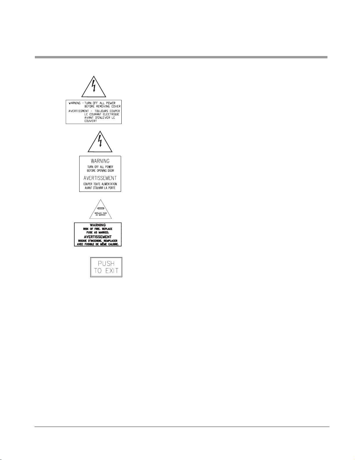
Safety Labels Used on the Equipment
The following safety labels are used on the 7800A washer:
You must remove all power to the washer before removing the back cover
to the washer chamber light assembly.
CAUTION
High voltage is present inside the control box. You must remove all power to
the washer before opening the door to the control box.
CAUTION
7800A Series Floor Mounted Cart and Utensil Washer
If you change a fuse, you must use an equivalently rated replacement.
Refer to “Spare Parts” on page C-2 in the Operator Manual for a list of spare
fuses.
If you are inside the washer when someone closes the door, press firmly on
this label on the inside of either door to stop the washer, if applicable, and
open the door.
61301604981 v
Page 8

vi
Page 9
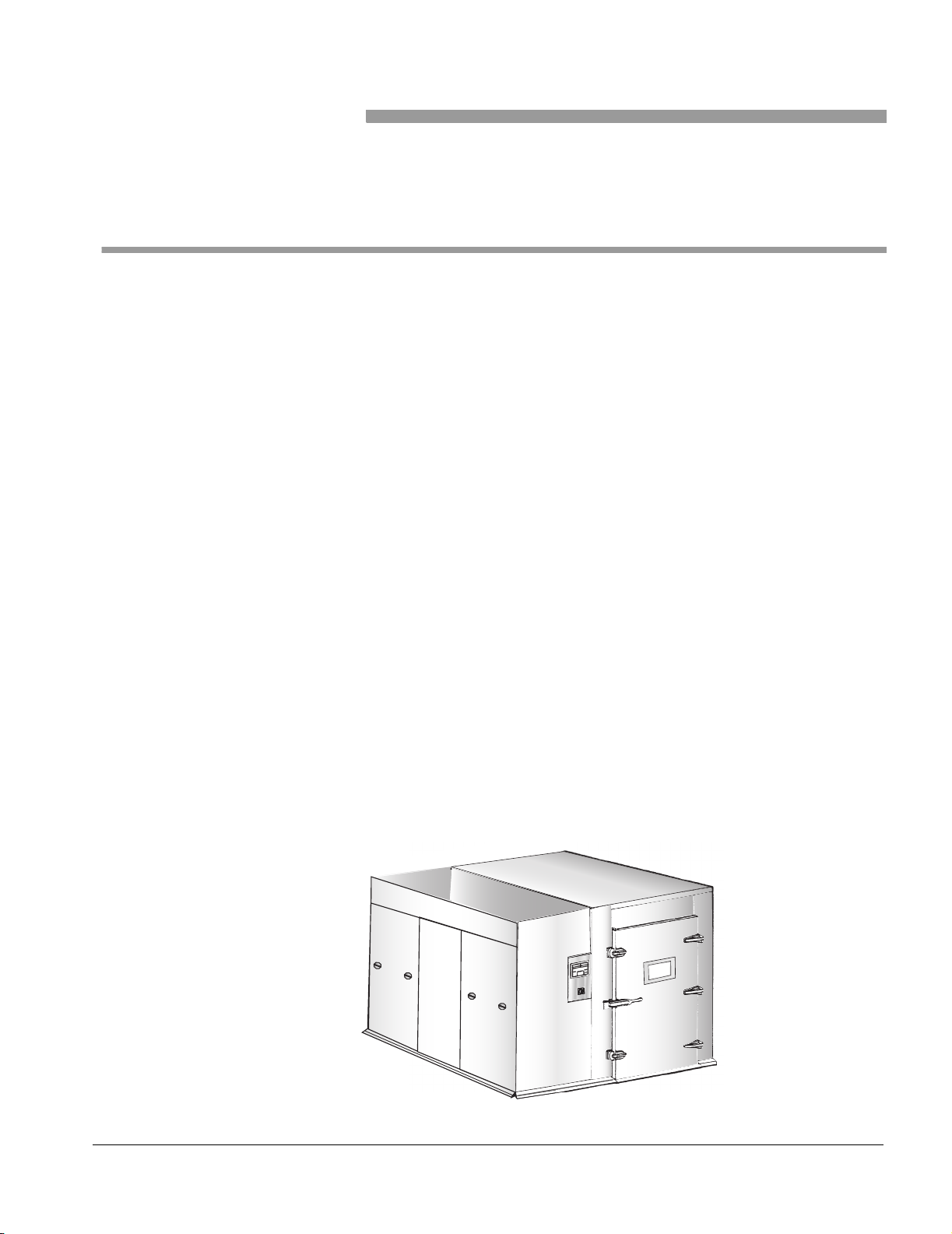
General Description
Section 1 Installation Requirements
The Getinge 7800A Series Floor Mounted Cart and Utensil Washer is a fully
automatic, large capacity, hydro-spray washer that is used to clean and dry
case carts, stands, utensils, containers, tote boxes, and similar bulk items.
The washer can be installed in a shallow pit or installed at floor level. When
installed in a pit, the floor of the washer's chamber is level with the room
floor, which allows the direct loading and unloading of carts. When the
washer is installed at floor level, the floor of the chamber is higher than the
room floor. Ramps are then provided as standard equipment to facilitate
loading and unloading.
The washer is designed for pass-through operation. Items to be cleaned are
placed in the washer’s compartment at the load end door. After cleaning, the
items are removed from the unload end door at the opposite end of the
washer.
The washer is generally installed in a facility’s decontamination room with
the unload end door opening out into a clean-preparation area. The unit is
available in three sizes, which are determined by compartment length: 80"
(2032 mm), 98" (2489 mm), and 112" (2845 mm), and which correspond to
models 78003A, 78004A, and 78005A, respectively.
Treatment solutions are delivered by separate oscillating (back and forth)
wash and rinse manifolds equipped with spray nozzles. Detergent and rinse
aid solutions are dispensed automatically as a standard feature.
A standard cycle consists of the following sequential phases: wash,
standard rinse (or optional purified rinse), drying, and exhaust. The length of
a cycle’s phase can be adjusted at the touch control panel.
Figure 1–1. 7800A Series Floor Mounted Cart and Utensil Washer
HW-001
61301604981 1–1
Page 10
Installation Requirements
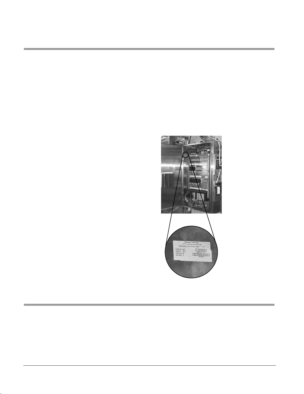
Model Identification
The rating plate for a 7800A washer is affixed to the inside of the control
box.
Record the model type and serial number (S/N) from the rating plate.
TYPE: _________________________________
SERIAL NO: ____________________________
Include the model type and serial number when communicating with
Getinge, USA.
Figure 1–2. Rating Plate Location
Utilities and Specifications
1–2
Utility requirements and specifications are included on sheet 2 of the
appropriate rough-in drawing (pit mounted or floor mounted version). Refer
to “Rough-In Drawings” on page 3-1.
Page 11

Installation Advisory
Washer Options
7800A Series Floor Mounted Cart and Utensil Washer
A 7800A washer is assembled at the factory, tested, and then disassembled
for shipment. Extensive on-site reassembly is required. The installation
instructions in this manual are intended as the primary reference for
accomplishing this reassembly. Every effort has been made to make this
information as accurate as possible.
Where applicable, installers should refer to specifications contained in the
product information documents, such as Assembly drawings, that have
been forwarded to local Getinge USA product support personnel. Rough-in
drawings can be found in “Rough-In Drawings” on page 3-1.
There are a number of options that may be included with your washer.
These options affect the procedures that apply to your specific installation.
Size (Load Length) There are three models of the 7800A washer, each corresponding to a
different compartment size, or load length (all models are the same width):
• 78003A is 80" (2032 mm) long
• 78004A is 98" (2489 mm) long
• 78005A is 112" (2845 mm) long
All models have five or six side panels and three top panels. The middle
panel on the front (service) side, the end panels on the rear, and the top
panels at each end are common for all three washer lengths. The sizes of
the end panels on the front side, the middle panel on the rear side (if
applicable), and the middle top panel depend on the washer length.
Floor Mount vs. Pit Mount A floor mounted washer requires the installation of ramps to provide access
to the washer. The interior floor of a pit mounted washer is level with the
finished floor of the facility.
Left Side vs. Right Side Controls
Left Hand vs. Right Hand Door Mounting
Barrier Flanges and Service Enclosure
The location of controls on your washer also determines the location of the
service area, as well as the barrier flanges and service enclosure that may
be provided with your washer.
The orientation of the load and unload door mountings determines the doors
and door panels for your washer.
Your installation may have barrier walls at the load or unload end of the
washer, or both, as well as have a service enclosure.
Electrical Service The electrical service at your facility determines the specific high voltage
devices (motors, pumps, etc.), transformer, and control box provided with
your washer.
61301604981 1–3
Page 12

Installation Requirements
Vented vs. Non-vented A vented washer has an automatic damper that connects directly to the
ventilation system of your facility. A non-vented washer has a condenser
(with associated electric and plumbing connections) mounted on the top of
the washer to remove moisture from the air that is exhausted from the
washer.
Purified Water Rinse An optional purified rinse phase uses water from the customer’s purified
water supply.
Printer If your washer has the printer option, the printer is already mounted on the
control box.
Seismic Anchoring If your washer has the seismic anchoring option, the sump assembly and
the mechanical core are secured to the floor.
Shipping Configuration
A disassembled 7800A washer is shipped on five pallets and one box of
various sizes. The maximum size of any one pallet may be as large as 130"
x 68", depending on the length of the unit. For stability during transit,
selected pallets are often pegged (with nails) to the floor of the truck.
Moving the disassembled washer from the truck to the installation site
requires the use of any available combination of the following:
• fork lift
• pallet jack
• dollies
• Johnson bars
A sufficient supply of commonly used fasteners (#10-32 and 1/4-20, for
example) is bagged for shipment. Speciality hardware and fasteners (door
latches and hinges, for example) are labeled and bagged separately for
shipment.
Many disassembled items, such as plumbing and panel sections, are
marked with handwritten numbers with black grease pen to identify their
location, orientation, or connection points. Take care not to inadvertently
smudge or erase these identifying marks.
1–4
Page 13

Tools and Materials Required
7800A Series Floor Mounted Cart and Utensil Washer
The following tables list the specific tools and materials required at the
installation site. Items marked with an asterisk * are supplied by Getinge
USA.
Table 1–1. Tools Required
Tool Quantity
Common Hand Tools Assorted
12' Pipe Clamp 2
C-Clamp 2
Johnson Bar 1
Pry/Pinch Bar 2
Caulking Gun 1
1/4-20 Tap, Short 1
10-32 Tap, Short 1
10-32 Tap, Long 1
#7 Drill Bit 2
#21 Drill Bit 2
Torpedo Level 1
4' Level 1
Scratch Awl 2
Tape Measure 1
Table 1–2. Materials Required
Material Quantity
* Silicone Adhesive 8 tubes
* Silicone Primer 1 pt
* Thinner 1 pt
* Polish 1 container
* Stainless Steel Nuts, Bolts,
Washers, Lock Washers
Assorted
* Wire Nuts, Tie Wraps Assorted
* 3" x 4" Stainless Steel Shims:
• 12 ga
• 14 ga
• 16 ga
• 18 ga
10
10
10
10
61301604981 1–5
Page 14

Installation Requirements
Material Quantity
1" x 4" x 6" Wood Block 2
2" x 4" x 52" Wood Block 4
Four rigid 3/4" x 60" long pipes are recommended for use if a floor mounted
washer is to be assembled out-of-position, then moved to its intended
operational site. The pipe is used to roll the washer into position after
assembly.
1–6
Page 15
Assemble the Washer Structure
This section contains procedures for assembling the basic structure of the
washer compartment. Refer to the following sections.
•“Install the Base/Sump Assembly” on page 2-1
•“Position the Mechanical Core” on page 2-3
•“Assemble the Washer Panels” on page 2-5
•“Channel Fillers and Threshold Assemblies” on page 2-11
•“Door Assembly” on page 2-12
Section 2 Installation
Install the Base/Sump Assembly
NOTE
General Instruction
If the load or unload end of the base is not marked, check the configuration
of the sump against the rough-in drawing (page 3-1) to determine the
correct orientation.
Some installation sites may have an existing wall in close proximity to the
non-service side of the washer that could interfere with the assembly of the
washer’s side panels. If this situation exists, you will have to seat the base
temporarily out-of-position until the side, top, and non-service side trim
panels are assembled. You can then maneuver the unit to its operating
position, where you can level and anchor it, if required.
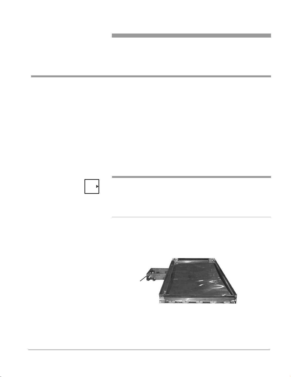
Installation
1. Move the base into its operating position.
Figure 2–1. Base/Sump Assembly
SERVICE SIDE
SUMP
2. Check the base for level.
Use the 4' level to check from all sides of the base and in
all directions. Adjust the level if necessary using the
stainless steel shims that are provided.
61301604981 2–1
Page 16
Installation
CAUTION
Failure to critically level the base will result in the misalignment of mounting
holes and will make assembly of the washer panels difficult.
If seismic anchoring is required, two 2 1/2" flanges (with anchor bolt holes)
must be bolted to the bottom frame of the base (one flange on each end of
the washer).
3. Drill holes for the anchors through the holes in the base
flange.
Table 2 –1. Drilling Specifications
Drill Bit Size 1/2”
Embedment 2 1/4” minimum
Torque 50 ft.-lb.
4. Secure the base to the floor using 1/2" bolt stud anchors
suitable for your floor structure.
NOTE
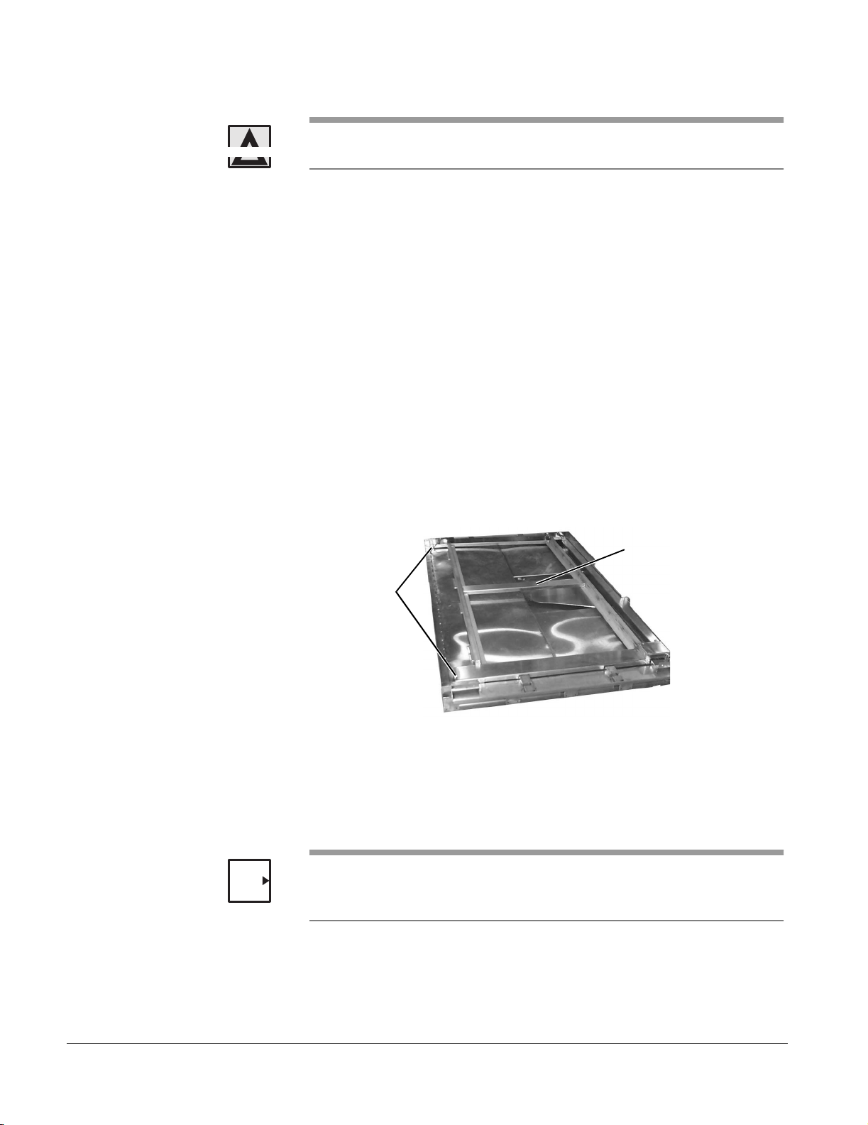
Figure 2–2. Track/Frame Assembly
TRACK/FRAME ASSEMBLY
FLOOR TILT
WELDMENTS
5. Lay the track/frame assembly into the base so that the floor
tilt weldments are on the non-service side of the washer.
6. Lay the floor grates in the track of the track/frame
assembly.
The 78003A model (88" long) has two 34" floor grates. The 78004A model
(106" long) has two 34" floor grates and one 16" floor grate. The 78005A
model (120" long) has two 34" floor grates and one 30 1/8" floor grate.
2–2
7. Lay the cardboard sheet over the floor grates to protect
from scratches while you complete the installation.
Page 17
7800A Series Floor Mounted Cart and Utensil Washer
Position the Mechanical Core
Objective
Position the mechanical core in its approximate location on the side of the
washer.
Installation
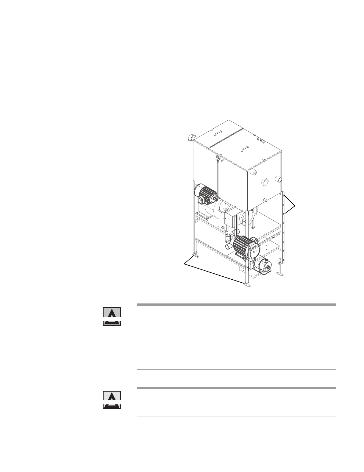
Refer to Figure 2–3. Mechanical Core.
Figure 2–3. Mechanical Core
MOUNTING
BRACKET
HOLES
(4 PLACES
EACH SIDE)
WARNING
CAUTION
ADJUSTABLE LEGS
(4 PLACES)
Silicone primer (orange) is extremely flammable, harmful if
swallowed or inhaled, and harmful to eyes or skin. Wear
protective clothing, gloves, and eyewear when using this
product. Keep it away from heat, sparks, and flames. Store
upright in a cool place, less than 30°C (85°F). Keep the
container closed when not in use. Use only in a well-ventilated
area. Avoid breathing vapors.
Silicone primer stains/discolors clothing, stainless steel surfaces, flooring,
etc. Avoid accidental spills. Avoid spreading this substance onto cosmetic
surfaces of the washer.
61301604981 2–3
Page 18

Installation
1. Using a fork lift, move the mechanical core into place on
the service side of the washer, approximately one inch
away from where the washer side walls will be.
NOTE
NOTE
NOTES
If your washer has a left-hand service area, one of the adjustable legs rests
on the pad on the right side of the sump box. If the washer has a right-hand
service area, one of the adjustable legs rests on the pad on the left side of
the sump box.
2. Clean mating surfaces on the dryer duct flange and around
the dryer duct cutout on the washer side panel with thinner,
and treat with silicone primer.
You will apply silicone caulk to the dryer flange after the washer walls are
assembled and just before you attach the mechanical core to the washer.
3. Set the washer light assembly on the dryer duct shelf.
• You will secure the light to the side panel after the washer panels are
assembled.
• If the return pump was shipped already attached to the sump, it may be
necessary to temporarily remove the pump until after the mechanical core
is positioned.
2–4
Page 19

Assemble the Washer Panels Objective
Assemble the door, side, and top panels. Install the required number of
interior side panel seam cover strips.
The 7800A washers have five or six side panels and three top panels. The
middle panel on the front (service) side, the end panels on the rear, and the
top panels at each end are common for all three washer lengths. The sizes
of the end panels on the front side, the middle panel on the rear side (if
applicable), and the middle top panel depend on the washer length. The
service side middle panel provides the cutouts for the dryer air duct and for
the wash and rinse manifolds. The top panels at each end of the washer
provide the cutouts for the intake and exhaust assemblies.
Each side panel carries a number that matches the number on the base’s
frame. The width of a top panel is the width of the washer (52"). The side
panels have 7/16" diameter holes that carry 3/8" thru bolts (five on each
side of the washer) to hold the panels together. The top panels have holes
to carry two thru bolts.
There is no established order to follow for panel assembly. You can start
from the load or the unload end. You can assemble all the vertical panels
first, followed by the top panels; or you can add individual top panels as you
erect the vertical panels. The method illustrated below starts from the load
end and progressively adds top panels as the vertical panels are erected.
7800A Series Floor Mounted Cart and Utensil Washer
NOTE
WARNING
CAUTION
Installation
You must clean all mating surfaces with thinner, then treat with silicone
primer, and then apply a generous amount of silicone sealant. This includes
all instances where panels are secured to the washer base or to other
panels, as well as the seam cover strips inside the washer.
Silicone primer (orange) is extremely flammable, harmful if
swallowed or inhaled, and harmful to eyes or skin. Wear
protective clothing, gloves, and eyewear when using this
product. Keep it away from heat, sparks, and flames. Store
upright in a cool place, less than 30°C (85°F). Keep the
container closed when not in use. Use only in a well-ventilated
area. Avoid breathing vapors.
Silicone primer stains/discolors clothing, stainless steel surfaces, flooring,
etc. Avoid accidental spills. Avoid spreading this substance onto cosmetic
surfaces of the washer.
61301604981 2–5
Page 20
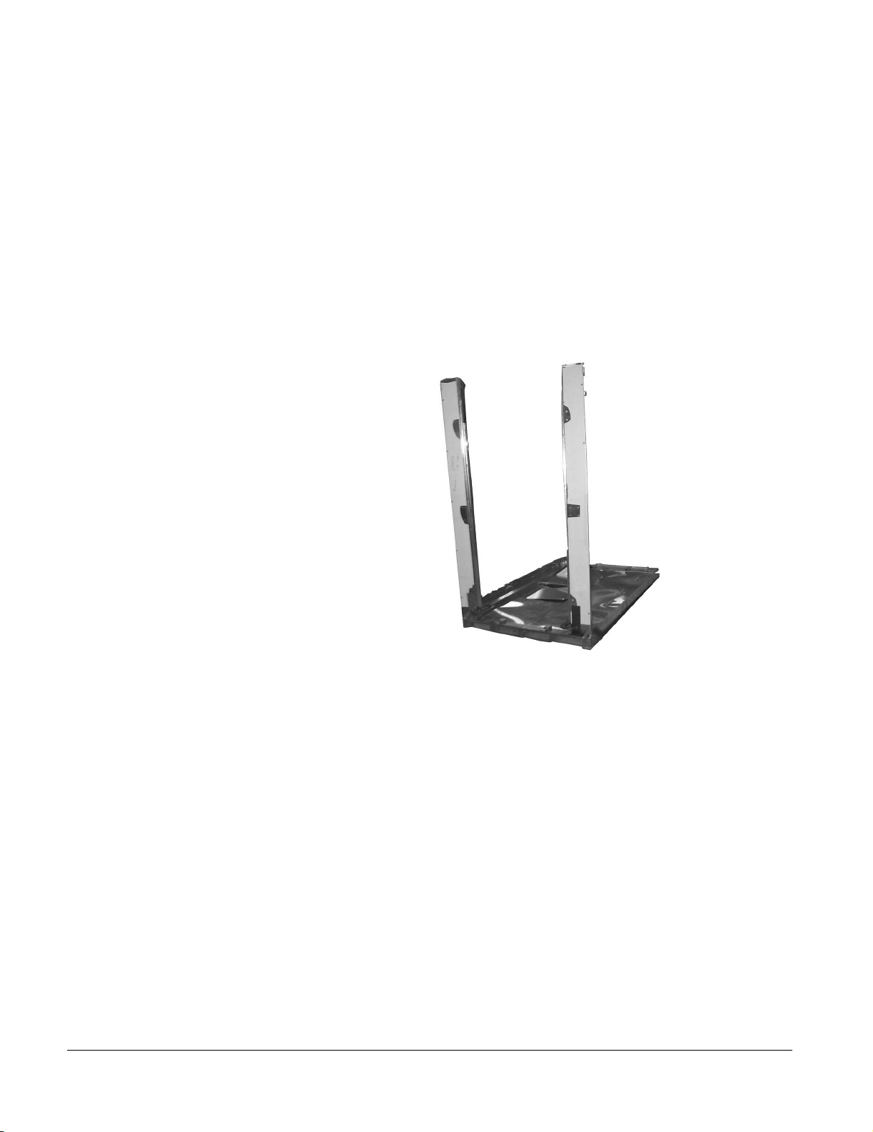
Installation
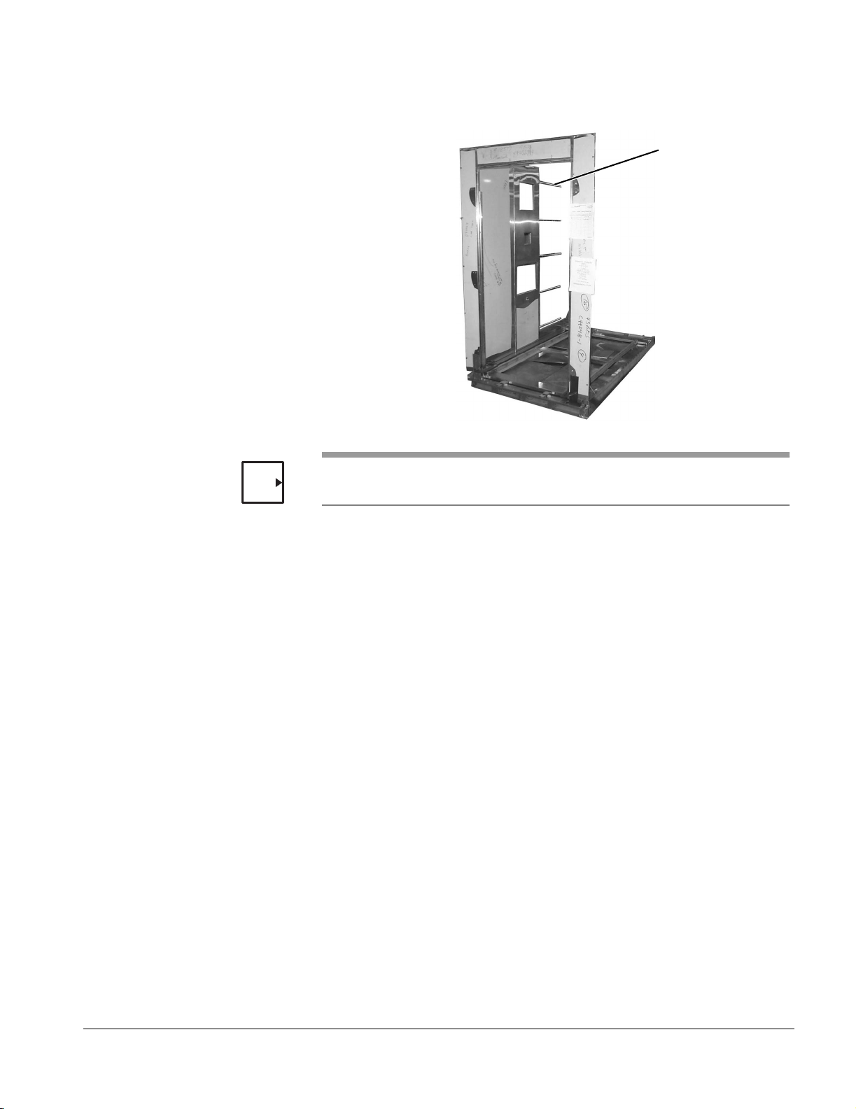
1. Attach the load end door panels to the base.
There are two vertical panels, each with three mounting
holes at the top to attach to the horizontal panel.
a. Position a vertical panel and use a C-clamp to hold the
panel in place temporarily.
b. Secure the bottom of the panel to the base frame with
four 1/4-20 fasteners (1/2" hex head bolts and lock
washers) and remove the clamp.
c. Repeat steps a and b for the other vertical panel.
Figure 2–4. Door Panels
2–6
d. Secure the horizontal panel between the two vertical
panels with 1/4-20 fasteners (six each 1/2" hex head
bolts and lock washers).
e. Plumb and square the door opening.
2. Attach the load end rear (non-service side) side panel to
the base and to the load end door.
a. Position the load end side panel.
b. Partially insert five 3/8" diameter thru rods through the
7/16" diameter holes to stabilize and align the side
panel with the door panel.
c. Use pipe clamps to draw the panels tight.
d. Secure the bottoms of the side panel to the base frame
with 1/4-20 fasteners (1/2" hex head bolts and lock
washers).
Page 21
7800A Series Floor Mounted Cart and Utensil Washer
Figure 2–5. Side Panels
THRU BOLTS
(5 EACH SIDE)
NOTE
Skip step 3 below if the washer does not have middle panel sections.
3. Attach the rear middle side panel to the base and to the
load end panel.
a. Remove the pipe clamps.
b. Position the middle rear side panel.
c. Extend the five thru bolts to stabilize and align the
panels with the load end side panel.
d. Attach the pipe clamps to draw these panels tight.
e. Secure the bottoms of the middle side panel to the
base frame with 1/4-20 fasteners (1/2" hex head bolts
and lock washers).
f. To ensure side panel alignment, attach C-clamps and
2x4" wooden blocks across the top edge of the
adjoining panels at the vertical seam.
61301604981 2–7
Page 22

Installation
4. Attach the unload end rear side panel to the base and to
the middle side panels.
a. Remove the pipe clamps.
b. Position the unload end rear side panel.
c. Extend the five thru bolts to stabilize and align this
panels with the previously erected panels.
d. Attach the pipe clamps to draw these panels tight.
e. Secure the bottom of the side panel to the base frame
with 1/4-20 fasteners (1/2" hex head bolts and lock
washers).
f. Move the C-clamp and 2" x 4" wooden block
assemblies to the vertical seams created by the
installation of these panels.
5. Repeat steps 2 through 4 to install the front (service side)
load, middle, and unload side panels, respectively.
6. Attach the unload end door panel to the base and to the
unload end side panels.
a. Remove the pipe clamps.
b. Position one vertical panel.
c. Extend the thru bolts on that side.
d. Attach the pipe clamps to draw the door panel tight.
e. Repeat steps b through d for the other vertical panel.
f. Secure the horizontal panel between the two vertical
panels with 1/4-20 fasteners (six each 1/2" hex head
bolts and lock washers).
g. Plumb and square the door opening.
h. Secure the thru bolts at both ends of the washer with
3/8" acorn nuts and flat washers.
i. Secure the bottom legs of the panel to the base frame
with four 1/4-20 fasteners (1/2" hex head bolts and lock
washers).
2–8
Page 23

7800A Series Floor Mounted Cart and Utensil Washer
7. Attach the load end top panel to the door panel and to the
load end side panels.
a. Position the load end top panel.
b. Secure the top panel to the door and load end side
panels with 1/4-20 fasteners (1-3/4" hex head bolts,
flat washers, and lock washers).
c. Partially insert the two remaining 3/8" diameter thru
bolts through the 7/16" diameter holes in the panel.
NOTE
Skip step 8 below if the washer does not have middle panel sections.
8. Attach the middle top panel to the load end top panel and
to the middle side panels.
a. Position the middle top panel.
b. Extend the two thru bolts.
c. Secure this panel to the middle side panels with 1/4-20
fasteners (1-3/4" hex head bolts, flat washers, and lock
washers).
9. Attach the unload end top panel to the unload end side
panels and to the unload end door panel.
a. Remove the C-clamp assemblies.
b. Position the unload end top panel.
c. Extend the two thru bolts.
d. Secure this panel to the unload end door and side
panels with 1/4-20 fasteners (1-3/4" hex head bolts,
flat washers, and lock washers).
e. Secure the thru bolts at both ends of the washer with
3/8" acorn nuts and flat washers.
61301604981 2–9
Page 24

Installation
10. Secure the mechanical core to the side panels.
a. Use the adjustable legs to align the holes in the
mounting bracket and in the dryer duct flange with the
corresponding holes in the side of the washer.
b. From inside the washer, apply silicone sealant to the
surface of the dryer flange.
c. Secure the mechanical core to the washer with eight
sets of 1/4-20 hardware.
d. Secure the dryer duct flange to the cutout in the
washer side panel with eight sets of 1/4-20 hardware.
NOTE
The mechanical core assembly will slowly move into place as you tighten
the fasteners.
11. Inside the washer, attach the panel seam cover strips over
the vertical seams between adjoining side panels using
#10-32 screws and lock washers.
2–10
Page 25
7800A Series Floor Mounted Cart and Utensil Washer
Channel Fillers and Threshold Assemblies
Objective
Install a channel filler on the floor just inside each washer door. Install a
threshold assembly just outside each washer door.
Installation
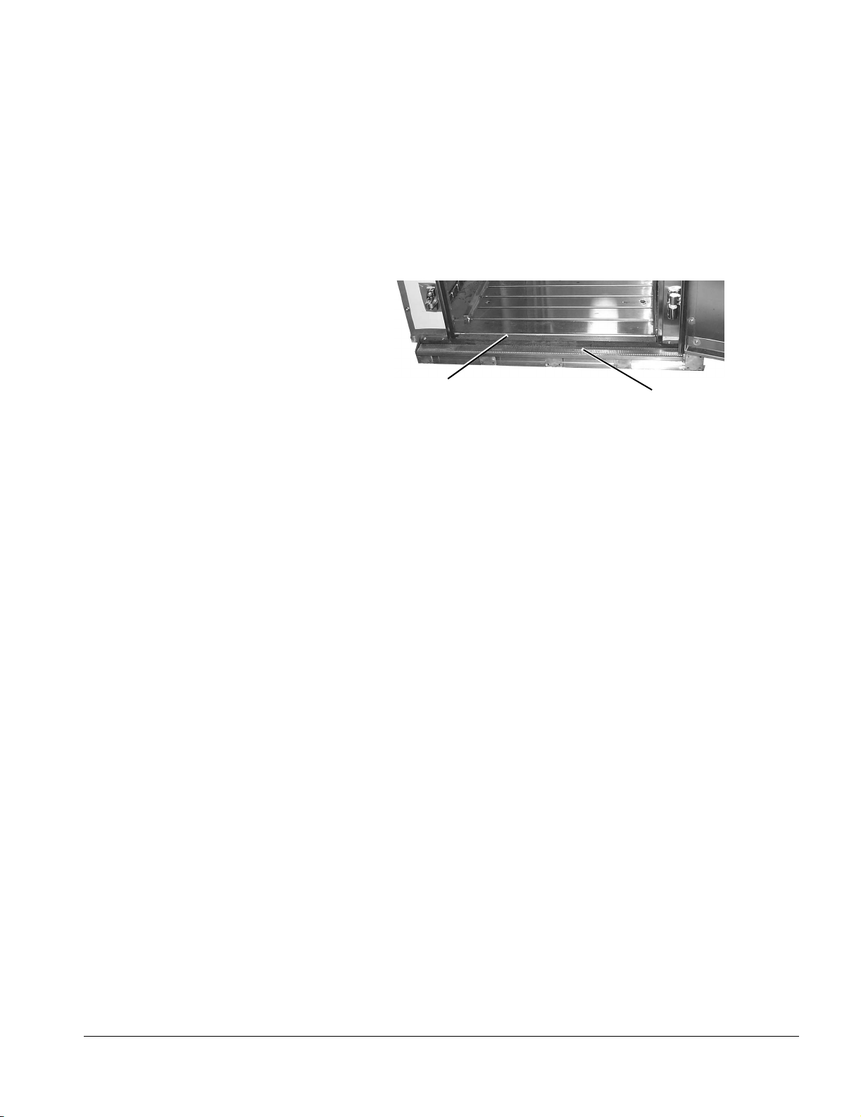
Refer to Figure 2–6. Channel Fillers and Threshold Assemblies.
Figure 2–6. Channel Fillers and Threshold Assemblies
CHANNEL FILLER
(1 EACH END)
THRESHOLD ASSEMBLY
(1 EACH END)
1. Position one channel filler at each end of the washer and
secure each to the base with two #10-32 x 3/8" phillips
head screws.
2. Position one threshold assembly at each end of the washer
with the gasket facing toward the inside of the washer and
secure each to the base with two #10-32 x 3/8" phillips
head screws.
61301604981 2–11
Page 26

Installation
Door Assembly Objective
Attach hardware to the doors and related door panels. Install the load and
unload end doors on the washer. Plumb and square both door openings.
Installation
Refer to Figure 2–7. Door Assembly.
Figure 2–7. Door Assembly
WARNING
DOOR LATCH
(2 PER DOOR)
HINGE MOUNT
(3 PER DOOR)
DOOR LATCH
RETAINERS
(2 PER DOOR)
DOOR HANDLE
DOOR HINGE
(3 PER DOOR)
A washer door is heavy and awkward to handle. Take care to
avoid crushing or strain injuries.
2–12
NOTE
The washer may be shipped with all of the hardware (hinges, latches, striker
plates, etc.) already mounted on both the doors and the door panels. If so,
start with step 3 below.
Page 27

7800A Series Floor Mounted Cart and Utensil Washer
1. Attach the following items to each door panel:
a. Attach three hinge mounts using 1/4-20 fasteners (nine
1" phillips head screws).
b. Attach two door latch retainers, two door latch shims,
and two spacers using 5/16-18 fasteners (four each 2"
hex head cap screws and lock washers).
c. Attach the striker plate assembly using 1/4-20
fasteners (four 2" phillips head screws).
2. Attach the following items to the door:
a. Attach two door latches using 5/16-18 fasteners (four
each 1" hex head cap screws and lock washers).
b. Attach three hinges using 1/4-20 fasteners (twelve
each 1” phillips head screws).
c. Attach the door handle using 5/16-18 fasteners (four
each 1" hex head cap screws and lock washers).
NOTE
3. Check the door opening for plumb and square. If
necessary, use the shims that are provided.
4. Mount the door on the washer.
a. Raise and maneuver the door until its hinge posts are
in vertical alignment over the three hinge mounts
attached to the door panel.
b. When aligned, lower the door and properly seat all
three posts in their respective mounts.
c. Check for correct operation of the door.
Repeat steps 1 through 4 for the other door assembly.
After the plumb and square of all doors is checked and corrected, it may be
easier to lift the doors off their hinges and set them aside until the washer
installation is complete.
61301604981 2–13
Page 28

Installation
Install Components on the Outside of the Washer
This section provides instructions for installing equipment on the outside of
the washer. The procedures are presented in a recommended order (some
larger components are easier if they are done earlier, for example). Refer to
the following sections.
•“Return Pump” on page 2-15
•“Washer Light Assembly” on page 2-16
•“Spray Manifold Drive Motor” on page 2-17
•“Control Box” on page 2-18
•“Dispenser Float Switch Junction Box, Detergent Dispenser, and Rinse
Aid Dispenser” on page 2-19
•“Emergency Stop Switch” on page 2-21
•“Unload End Indicator Panel Box” on page 2-22
•“Door Proximity Switches” on page 2-23
2–14
Page 29
Return Pump Objective
Install the return pump.
Installation
7800A Series Floor Mounted Cart and Utensil Washer
NOTE
The return pump may be shipped from the factory already installed in the
sump.
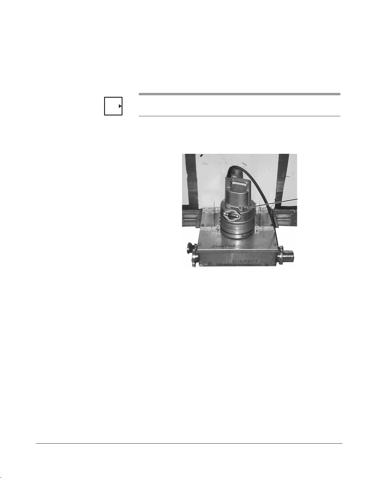
Refer to Figure 2–8. Return Pump.
Figure 2–8. Return Pump
RETURN PUMP
1. Slide the low suction collar over the bottom of the return
pump and position the pump in the sump.
2. Secure the pump to the flange on the front sump cover by
attaching the two ends of the metal strap with 5/16"-18
fasteners (2" hex head cap screws and lock washers) to
the flange.
61301604981 2–15
Page 30

Installation
Washer Light Assembly Objective
Install the interior light in the cutout located on the front (service side) wall.
Installation
1. Align the holes in the light assembly with the holes
surrounding the cutout in the front panel.
2. Secure the light assembly to the front panel with eight #10-
32 fasteners (phillips head screws and flat washers) as
shown in Figure 2–9.
Figure 2–9. Washer Light Assembly
#10-32 FASTENERS
(8 PLACES)
2–16
Page 31

Spray Manifold Drive Motor Objective
Assemble the spray manifold drive’s flange bearing and the spray manifold
drive motor.
Installation
Refer to Figure 2–10. Spray Manifold Drive Flange Bearing.
Figure 2–10. Spray Manifold Drive Flange Bearing
7800A Series Floor Mounted Cart and Utensil Washer
NOTE
LOAD END
MOUNTING
BRACKET
HOLES
(6 PLACES)
FLANGE BEARING
3/8-16 FASTENERS
(4 PLACES)
1. Use 3/8"-16 fasteners (four each 1" hex head cap screws
and lock washers) to loosely secure the flange bearing in
position at the upper corner of the load end side panel.
You will tighten the bearing after you assemble the drive shaft and couple it
to the drive motor (refer to “Chain Drive Assembly” on page 2-36).
Figure 2–11. Manifold Driver Motor
1/4-20 FASTENERS
(6 PLACES)
2. Position the spray manifold drive motor and bracket over
the six threaded holes located in the panel directly below
the flange bearing and use 1/4-20 fasteners (six each 3/4"
hex head cap screws, lock washers, and flat washers) to
secure the mounting fixture to the panel.
3. Slip the proximity switch collar over the drive shaft of the
motor and secure by tightening the hex head cap screw.
61301604981 2–17
Page 32

Installation
Control Box Objective
Attach the control box to the load end side panel.
Installation
Refer to Figure 2–12. Control Box.
Figure 2–12. Control Box
1/4-20 FASTENERS
(4 PLACES)
1. Remove the pins from the door hinges and set the door
aside.
2. Loosely secure one 1/4-20 fastener (4 each 3/4" hex head
cap screws, flat washers, and lock washers) to the panel.
3. Position the control box so that the mounting holes are
aligned with the screws and then hang the control box.
4. Insert the remaining three sets of fasteners.
5. Tighten the four screws to secure the control box to the
panel.
6. Install the door on the control box.
2–18
Page 33

7800A Series Floor Mounted Cart and Utensil Washer
Dispenser Float Switch Junction Box, Detergent Dispenser, and Rinse Aid Dispenser
Objective
Install the junction box for the detergent and rinse aid dispenser float
switches on the front (service side) panel at the load end of the washer.
Install the detergent and rinse aid dispensers.
Installation
Refer to Figure 2–13. Float Switch Junction Box and Dispensers
Figure 2–13. Float Switch Junction Box and Dispensers
FLOAT SWITCH
JUNCTION BOX
RINSE AID
DISPENSER
DETERGENT
DISPENSER
NOTE
1. Install the float switch junction box.
a. Remove the face plate of the box.
b. Align the mounting holes in the back of the box with the
two #10-32 threaded holes on the front side panel at
the load end of the washer.
c. Use #10-32 fasteners to secure the box to the panel.
d. Install the face plate.
If a remote chemical pumping station is being used, it is required that the
stations are programmed to pump for the entire time that the output
electrical signals are active. The wash control program varies the length of
the chemical pumping signal depending on the specified cycle parameter.
2. Install the rinse aid dispenser.
a. Position the rinse aid pump and bracket on the side
panel and align with the holes in the panel.
b. Secure the pump mount to the washer with four #10-32
fasteners (phillips head screws and lock washers).
61301604981 2–19
Page 34

Installation
3. Install the detergent dispenser.
a. Align the mounting holes in the back plate with the set
of threaded holes in the panel.
b. Use two #10-32 fasteners to secure the dispenser in
place.
2–20
Page 35

Emergency Stop Switch Objective
Attach the emergency stop switch to the side panel of the washer. The
switch is mounted at the load end of the washer, under the control box.
Installation
Refer to Figure 2–14. Emergency Stop Switch.
Figure 2–14. Emergency Stop Switch
7800A Series Floor Mounted Cart and Utensil Washer
1/4-20 FASTENERS
(4 PLACES)
MOUNTING
BRACKET
EMERGENCY STOP
SWITCH
1. Mount the emergency stop switch to the mounting bracket
using two 1/4-20 fasteners (hex head cap screws, lock
washers, and flat washers).
2. Align the two holes in the mounting bracket with the holes
on the load end side panel.
3. Secure the bracket and switch to the washer with two 1/4-
20 fasteners (hex head cap screws, lock washers, and flat
washers).
61301604981 2–21
Page 36

Installation
Unload End Indicator Panel Box
Objective
Mount the indicator panel box on the unload end of the washer.
Installation
Refer to Figure 2–15. Unload End Indicator Panel Box.
Figure 2–15. Unload End Indicator Panel Box
1. Remove the face plate of the box.
2. Align the mounting holes in the back of the box with the two
#10-32 threaded holes at the edge of the unload end door
panel.
3. Use #10-32 fasteners to secure the box to the panel.
4. Install the face plate.
The box overhangs the panel to permit the routing of its electrical cable.
2–22
Page 37

Door Proximity Switches Objective
Install a proximity switch assembly on both the load and the unload end
door panels.
The sensors are interchangeable.
Installation
Refer to Figure 2–16. Door Proximity Switches.
Figure 2–16. Door Proximity Switches
#6-32 FASTENERS
7800A Series Floor Mounted Cart and Utensil Washer
(2 PLACES)
1. Align the proximity switch with the threaded mounting holes
in the door panel.
2. Use two #6-32 fasteners to secure the switch to the door
panel.
3. Adjust the switch as necessary to provide 1/16" to 1/8"
clearance to the actuator block on the door.
4. Attach the cover plate over the switch with two screws.
5. Repeat steps 1 through 4 to install the other switch
assembly on the other door.
61301604981 2–23
Page 38

Installation
Install Components on Top of the Washer
There are a number of components that are installed on the top panels of
the washer. Although there is no specific order in which the components
should be installed, the list below presents the items in a recommended
order. Refer to the following sections.
•“Power Floor Tilt Pulley System” on page 2-25
•“Transformer” on page 2-27
•“Exhaust Assembly” on page 2-28
•“Intake Assembly” on page 2-29
Before installing any component on top of the washer, you must ensure that
CAUTION
the door openings are plumb and square. Failure to do so can result in
doors that do not open and close correctly, as well as water leaks.
2–24
Page 39

7800A Series Floor Mounted Cart and Utensil Washer
Power Floor Tilt Pulley System
Objective
Install the power tilt floor pulley system. The top panels have 1/4-20
threaded holes to mount the system’s three components. The actuator
assembly is installed across the middle roof panel with the pulley end along
the non-service side of the washer. The pulley cables run from the actuator
along the non-service side to the pulley mounts on each end of the washer.
Installation
Refer to Figure 2–17. Power Floor Tilt Pulley Assembly for steps 1 through
3.
Figure 2–17. Power Floor Tilt Pulley Assembly
ACTUATOR
TILT
PROXIMITY
SWITCH
1/4-20 FASTENERS
LEVEL
PROXIMITY
SWITCH
NON-SERVICE SIDE
1. Install the following components on the non-service side of
the washer’s top panels:
a. Align the actuator with the holes in the top panel and
secure with 1/4-20 fasteners (four each 1/2" hex head
screws, lock washers, and flat washers). The actuator
is mounted near the middle of the washer. The pulleys
are oriented so that the cables run the length of the
washer on the non-service side.
61301604981 2–25
Page 40

Installation
Figure 2–18. Pulley Mount
PULLEY MOUNT
1/4-20 FASTENERS
b. Secure the load end pulley mount to the corner of the
load end top panel with 1/4-20 fasteners (two each 1/2"
hex head screws, lock washers, and flat washers).
c. Secure the unload end pulley mount to the corner of
the unload end top panel with 1/4-20 fasteners (two
each 1/2" hex head screws, lock washers, and flat
washers).
2. Route the pulley cables from the actuator, through the
pulley mounts, and then down through the two gasketed
cable holes in the paneling to the compartment floor.
NOTE
You may have to enlarge a gasket hole with a drill if the cable does not fit
through the hole.
3. Slide the black protective cable sleeves over the sections
of the cables inside the washer.
Figure 2–19. Attaching Cable to Floor Lift Weldment
CABLE
FASTENER
FLOOR TILT
WELDMENT
4. Using two cable fasteners each, secure each of the two
pulley cables to its corresponding floor tilt weldment.
5. Using #6-32 fasteners, attach the two limit switches to the
actuator’s mounting plate (refer to 2–17).
2–26
Page 41

Transformer Objective
If applicable, install the transformer to the top of the washer. The specific
transformer used with your washer depends on the house-supplied voltage.
Installation
Refer to Figure 2–20. Transformer.
Figure 2–20. Transformer
7800A Series Floor Mounted Cart and Utensil Washer
LOAD END
NOTE
Transformers are sized differently but are generally located on the service
side of the load end top panel.
1. Match the transformer’s mounting holes to the threaded
holes in the panel.
2. Secure the transformer to the panel with appropriate
fasteners.
61301604981 2–27
Page 42

Installation
Exhaust Assembly Objective
Mount the exhaust assembly on the roof panel at the load end of the
washer. The exhaust assembly is installed on vented units only.
Installation
Figure 2–21. Exhaust Assembly
DAMPER
MOTOR
#10-32 FASTENERS
(6 PLACES)
WARNING
CAUTION
Silicone primer (orange) is extremely flammable, harmful if
swallowed or inhaled, and harmful to eyes or skin. Wear
protective clothing, gloves, and eyewear when using this
product. Keep it away from heat, sparks, and flames. Store
upright in a cool place, less than 30°C (85°F). Keep the
container closed when not in use. Use only in a well-ventilated
area. Avoid breathing vapors.
Silicone primer stains/discolors clothing, stainless steel surfaces, flooring,
etc. Avoid accidental spills. Avoid spreading this substance onto cosmetic
surfaces of the washer.
1. Clean all mating surfaces with thinner, treat with silicone
primer, and then apply silicone sealant to the mating
surface surrounding the cutout on the roof panel.
2. Position the exhaust assembly on the cutout and secure
with #10-32 fasteners (six each hex head cap screws, lock
washers, and flat washers).
2–28
3. Position the damper motor and secure with two #10-32
fasteners.
4. Verify that the damper arm freely engages and operates
the exhaust plate.
Page 43

Intake Assembly Objective
#
Mount the intake assembly on the top of the washer above the unload end
door.
Installation
Refer to Figure 2–22. Intake Assembly.
Figure 2–22. Intake Assembly
10-32 FASTENERS
(4 PLACES)
7800A Series Floor Mounted Cart and Utensil Washer
WARNING
CAUTION
Silicone primer (orange) is extremely flammable, harmful if
swallowed or inhaled, and harmful to eyes or skin. Wear
protective clothing, gloves, and eyewear when using this
product. Keep it away from heat, sparks, and flames. Store
upright in a cool place, less than 30°C (85°F). Keep the
container closed when not in use. Use only in a well-ventilated
area. Avoid breathing vapors.
Silicone primer stains/discolors clothing, stainless steel surfaces, flooring,
etc. Avoid accidental spills. Avoid spreading this substance onto cosmetic
surfaces of the washer.
1. Clean all mating surfaces with thinner, treat with silicone
primer, and then apply silicone sealant to the mating
surface surrounding the cutout on the roof panel.
2. Position the intake assembly on the cutout with the filter
above the door and secure with #10-32 fasteners (four
each hex head cap screws, lock washers, and flat
washers).
61301604981 2–29
Page 44

Installation
Plumbing
The washer plumbing is designed with a number of quick-disconnect joints
that enable service personnel to isolate problems and to replace
components easily. When a washer is disassembled at the factory for
shipment to a customer, plumbing sections are removed for efficient packing
and quick assembly at the installation site. All plumbing sections are tagged
at both ends to indicate what the section is connected to. The following
information provides only general descriptions of the completed plumbing.
1. Connect the 2" red flex hose from the discharge of the
wash pump to the wash manifold fitting on the side of the
washer.
2. Connect the 3/4" red flex hose from the output of the
booster heater to the rinse manifold on the side of the
washer.
3. Attach the red dryer hose to the flange on the intake
assembly (on the top of the washer) and to the flange on
the dryer condenser. Secure each end with a hose clamp.
NOTE
Secure the dryer hose where necessary to prevent rubbing against sharp
edges.
4. Connect the 2" red flex tank fill hose to the discharge of the
return pump.
5. Connect the drain box assembly to drain.
2–30
Page 45

7800A Series Floor Mounted Cart and Utensil Washer
Figure 2–23. Drain Box Assembly
TANK DRAIN
DRAIN TEMPERING
NON-VENTED
CONDENSER
TANK OVERFLOW
SUMP DRAIN
SUMP OVERFLOW
Refer to Figure 2–23. Drain Box Assembly for steps 6 through 11 below.
CONDENSER
(OPTION)
6. Connect the discharge of the tank drain valve to the tank
drain fitting on the drain box assembly with 2" red flex
hose. Secure at each end with hose clamps.
7. Connect the 3" black flex hose from the overflow fitting on
the tank to the tank overflow fitting on the drain box
assembly. Secure at both ends with hose clamps.
8. Connect the 2" sump drain valve (with black flex hose) to
the drain fitting on the sump and to the sump drain fitting
on the drain box assembly. Secure at both ends with hose
clamps.
9. Use 3" black flex hose to connect the overflow fitting on the
sump with the sump overflow fitting on the drain box
assembly. Secure at both ends with hose clamps.
10. Connect the 3/4" red flex hose from the cold water supply
to the drain tempering fitting on the drain box assembly.
Secure with a hose clamp.
11. Connect the 3/4" clear flex hose from the dryer condenser
to the condenser fitting on the drain box assembly. Secure
with a hose clamp.
12. If your washer has the non-vented option, connect the 3/4"
red flex hose from the exhaust condenser to the other
condenser fitting on the drain box assembly. Secure with a
hose clamp.
61301604981 2–31
Page 46

Installation
Electrical Wiring
Objective
Make all required electrical wire connections between the electrical
components and the control box.
Installation
1. Route all component electrical cables, including
thermocouple cables, from the control box to the
appropriate electrical component.
Refer to Table 2–2 for the routings.
2. Connect the cables to the corresponding electrical
component.
Most cables have keyed connectors that plug in and are secured with
threaded fittings. Cables that must be wired to the component are noted in
Ta b le 2–2.
NOTE
Attach all solenoid coil housings to their related solenoid valve bodies, as
shown in Figure 2–24.
Figure 2–24. Solenoid Valve Assembly
The actual configuration for your washer may vary from that shown.
2–32
Page 47

7800A Series Floor Mounted Cart and Utensil Washer
Table 2 –2. Control Box Cable Connections
Jack Cable P/N Cable Label Destination
J1-J2 Not used.
J3 61301604989 P3 – 1PX Load End Door Proximity
Switch 1PX
J4 61301604989 P4 – 2PX Unload End Door Proximity
Switch 2PX
J5-J6 Not used.
J7 61301603975 P7 – 6PX Level Proximity Switch 6PX
J8 61301603975 P8 – 7PX Tilt Proximity Switch 7PX
J9 61301603976 P9 –1MV Tank Drain Valve 1MV
J10 61301603981 P10 – 9MTR Exhaust Damper Motor 9MTR
J11 61301603981 P11 – 8MTR Dryer Damper Motor 8MTR
J12 Not used.
J13 Y960456 P13 – 3SV Tank Fill Solenoid Valve 3SV
J14 Y960456 P14 – 4SV Tank Steam Solenoid Valve
4SV
J15 Y960456 P15 – 5SV Rinse Steam Solenoid Valve
5SV
J16 Y960456 P16 – 1SV Dryer Steam Solenoid Valve
1SV
J17 Not used.
J18 Y960456 P18 – 2SV Dryer Condenser Cold Water
Solenoid Valve 2SV
J19 Not used.
J20 Y960456 P20 – 6SV Exhaust Duct Cold Water
Solenoid Valve 6SV (Nonvented units only)
J21 P21 – 14SV Drain Tempering Solenoid
Valve (HI) 14SV
J22 61301603980 P22 – 1LT/2LT Unload End Indicator Box
J23 61301603988 P23 – 12MTR Detergent Pump 12MTR
J24 61301603978 P24 – 13MTR Rinse Aid Pump 13MTR
J25 61301604985 P25 – 1LE/2LE/
3LE
J26 61301603983 P26 – 1ACT Floor Tilt Actuator 1ACT
J27 61301603984 P27 – 3LT Washer Compartment Light
J28–
J30
J31 61301603985 P31 – 1TC Circulation Tank Thermocou-
J32 61301603985 P32 – 2TC Dryer Thermocouple 2TC
J33 Not used.
J34 61301603985 P34 – 4TC Rinse Water Thermocouple
J35 61301604988 P35 – 3JB Float Switch Junction Box 3JB
Not used.
Circulation Tank High, Low,
and Refresh Water Level
Probes 1LE/2LE/3LE
3LT
ple 1TC
4TC
61301604981 2–33
Page 48

Installation
Jack Cable P/N Cable Label Destination
J36 61301604134 P36 – 1MTR Wash Pump 1MTR
J37 61301603987 P37 – 2MTR Dryer Blower Motor 2MTR
J38 Not used.
J39 61301603988 P39 – 4MTR Manifold Drive Motor 4MTR
J40 P40 – TTransformer T
J41–
J49
J50 61301603976 P50 – 2MV Sump Drain Valve 2MV
J51 B010359 P51 – 15MTR Rinse Pump 15MTR
J52 Not used.
J53 61301604987 P53 – 3S Emergency Stop Switch 3S
J54 Not used.
J55 Y960456 P55 – 11SV Rinse Water Solenoid Valve
J56–
J57
J58 P58 – 14MTR Return Pump 14MTR
J59 Y960789 P59 – 5PX Manifold Drive Motor Proximity
J60–
J61
J62 P62 – 13SV Pure Rinse Water Solenoid
J63 P63 – 5MTR Exhaust Blower 5MTR
J64 P64 – 10SV Drain Tempering Solenoid
Not used.
11SV
Not used.
Switch 5PX
Not used.
Valve 13SV
Valve (LO) 10SV
2–34
Page 49

7800A Series Floor Mounted Cart and Utensil Washer
Install Components on the Inside of the Washer
This section provides instructions for installing equipment on the inside of
the washer. The procedures are presented in a recommended order. Refer
to the following sections.
•“Drive Chain Tension Idlers and Idler Bearing” on page 2-35
•“Chain Drive Assembly” on page 2-36
•“Spray Manifold Supports and Spray Manifolds” on page 2-38
•“Manifold Cover, Manifold Guard Tubes, Wash Cart Tubes” on page 2-41
•“Emergency Stop Switch Cable” on page 2-43
Drive Chain Tension Idlers and Idler Bearing
Objective
Install the following components inside the washer compartment:
• Two drive chain tension idlers
• Idler bearing
Installation
Refer to Figure 2–25. Drive Chain Tension Idlers and Idler Bearings.
Figure 2–25. Drive Chain Tension Idlers and Idler Bearings
1. Mount the two drive chain tension idlers, one on either side
of the compartment, with 1/4-20 fasteners (four each 3/4"
hex head cap screws and lock washers).
2. Mount the idler bearing for the manifold drive shaft as
shown. Secure with 1/4-20 fasteners (three each 1" hex
head cap screws, lock nuts, lock washers, and flat
washers).
61301604981 2–35
Page 50

Installation
Chain Drive Assembly Objective
Install the drive shaft, drive chains, and push rod that comprise the chain
drive assembly.
Installation
Refer to Figure 2–26. Chain Drive Assembly.
Figure 2–26. Chain Drive Assembly
1. Insert the drive shaft key into the keyway in the spray
manifold drive motor that you installed previously.
2. Mount the drive shaft seal to the inside of the upper corner
of the load end side panel, opposite the flange bearing that
you installed previously.
a. Position the seal so its rubber side is against the panel.
b. Secure in place with 1/4-20 fasteners (four each 3/8"
pan head screws and lock washers).
3. Insert, but do not fasten, the motor and idler ends of the
shaft assembly into the shaft coupling.
4. Hang the two push rod/chain assemblies from the shaft
assembly.
5. Fit the idler end into the idler bearing that you installed
previously.
6. Extend the motor end through the seal and flange bearing,
and then engage the key (installed in step 1) with the
shaft’s keyway.
2–36
Page 51

7800A Series Floor Mounted Cart and Utensil Washer
7. Rotate the idler end of the shaft until its sprocket key is in
alignment with the sprocket key at the shaft’s motor end.
8. Secure the shaft ends to the shaft coupling with two #10-32
bolts and jam nuts.
9. Adjust the proximity switch so that the gap between the
switch and the sensing collar on the drive shaft is less than
or equal to 2 mm (0.08").
10. Use #10-32 fasteners (four each 1/4" pan head screws and
lock washers) to attach the drive coupling guard to the
motor’s mounting fixture.
NOTE
You can wait until the operation of the motor has been checked by product
support personnel before installing the drive coupling guard.
11. Insert the ends of the push rod chain assembly into the
push rod sleeve.
12. Fit the chains onto their related sprockets at the drive shaft
and at the drive chain tension idlers that you installed
previously.
Make sure the ends of the push rod are seated on
matching sprocket teeth.
13. Adjust the chain tension so there is no more than 1" of play
in either line.
You can loosen a tension idler’s 3/8-16 bolt to permit
movement of its sprocket. Turning the 1/4-20 adjustment
bolt repositions the sprocket, thereby increasing or
decreasing chain tension.
61301604981 2–37
Page 52

Installation
Spray Manifold Supports and Spray Manifolds
Objective
Install the two spray manifold supports, one on either side of the washer
compartment, and then install the two spray manifolds.
Installation
Refer to Figure 2–27. Spray Manifold Support.
Figure 2–27. Spray Manifold Support
1. Seat the ends of the spray manifold supports in the
uppermost captive brackets that are welded to the inside of
the two door panels.
2. Apply silicone sealant to four #10-32 fasteners, and then
secure the mounting angles of the supports to the side
panels.
2–38
Page 53

7800A Series Floor Mounted Cart and Utensil Washer
3. Attach 1/4-20 bolts and nylock nuts to the captive brackets
to ensure the ends of the spray manifold supports remain
in place.
Figure 2–28. Spray Manifold Assembly
4. Attach the rinse and the wash hose connectors to the inlet
ports in the middle side panel.
5. Set the spray manifolds on the manifold supports.
6. Connect the manifolds at the top with two stringers. Orient
the stringers so that their push pins are directed toward the
load end. Use 5/16-18 fasteners to secure the stringers to
the manifolds.
61301604981 2–39
Page 54

Installation
7. Use 5/16-18 fasteners to connect the manifolds at the
bottom with two connector bars. Use two sets of fasteners
at the end of each connector bar.
Figure 2–29. Wash and Rinse Manifold Hoses
WASH
MANIFOLD
HOSES
RINSE
MANIFOLD
HOSES
8. Install the wash and rinse hoses between the manifold and
the panel hose connectors. Secure each end of the hoses
with two hose clamps. Position the hoses so they rest
against the panels and not obstruct manifold movement.
2–40
Page 55

7800A Series Floor Mounted Cart and Utensil Washer
Manifold Cover, Manifold Guard Tubes, Wash Cart Tubes
Objective
Install the following components inside the washer:
• Manifold cover
• Four manifold guard tubes
• Two wash cart guide tubes
Installation
Refer to Figure 2–30. Manifold Cover, Manifold Guard Tubes, Wash Cart
Guide Tubes.
Figure 2–30. Manifold Cover, Manifold Guard Tubes, Wash Cart Guide
Tubes
1. Position the manifold cover on top of the spray manifolds.
Secure the cover in place at the load and unload ends with
four #10-32 fasteners (two at each end of the cover).
61301604981 2–41
Page 56

Installation
2. Attach the four manifold guard tubes to the captive
brackets welded to the load and unload end door panels.
a. Place a 1/4-20 bolt through the manifold guard tube
brackets on each end of the washer at the appropriate
level and secure with a lock nut.
b. Insert each end of the manifold guard tube so that it
rests on the bolt inside the bracket.
NOTES
NOTE
• There is one manifold guard tube that has three eyebolts to
accommodate the emergency stop cable. This tube should be installed as
the middle of the three tubes that are installed on the service side of the
washer. This tube is also secured to the bracket through holes in the tube,
rather than by resting on the bolt.
• You should position the guard tubes to accommodate the equipment to
be washed.
3. Install the wash cart guide tubes.
There are two or three guide tubes depending on the length of the washer:
the 78003 has two guide tubes; the 78004 and 78005 have three guide
tubes (the shorter guide tube is installed between the other two).
a. Center one of the long wash cart guide tubes on the
load end floor grate.
b. Butt the edges of the tube’s mounting brackets against
the floor frame over the sump.
c. Using the brackets as templates, drill and tap four 1/4-
20 holes into the grate. Make sure the holes are
located against the inside of the bracket slots so the
tube can to be adjusted back toward the center line of
the floor.
2–42
d. Repeat steps a through c for the remaining wash cart
guide tube.
e. Secure both tubes to the floor with 1/4-20 fasteners.
Page 57

7800A Series Floor Mounted Cart and Utensil Washer
Emergency Stop Switch Cable
Objective
Install the emergency stop cable. The cable runs along the service side of
the washer, passes through the side panel, and connects to the emergency
stop switch on the service side of the washer.
Installation
Install the emergency stop cable on the front side of the washer and
connect to the switch on the outside of the washer.
1. Refer to Figure 2–31. At the unload end of the washer,
attach one end of the cable to the guide rail bracket. Loop
the cable through the next hole in the bracket above the
guide rail and secure with a cable fastener.
Figure 2–31. Emergency Cable Connection
EMERGENCY
STOP CABLE
CABLE CONNECTOR
2. As shown in Figure 2–32, feed the cable through the three
eyebolts on the guide rail to the load end, around the two
weldments on the front side panel, and through the
opening in the front side panel.
Figure 2–32. Emergency Stop Cable
LOAD END
FRONT
WELDMENT
EMERGENCY
EYE BOLT
LOAD END
FRONT
WELDMENT
STOP CABLE
3. Secure the end of the cable to the emergency stop switch
assembly with a cable fastener as shown in Figure 2–14.
61301604981 2–43
Page 58

Installation
Final Installation Tasks
This section provides instructions for completing the installation of the
washer. Refer to the following sections.
•“Final Door Assembly” on page 2-45
•“Dispenser Tubing” on page 2-46
•“Barrier Flanges” on page 2-48
•“Pit Covers” on page 2-49
•“Service Area Enclosure (Option)” on page 2-50
•“Ramps” on page 2-51
•“Exhaust Connection” on page 2-52
•“Plumbing System Connections” on page 2-52
•“Electrical Supply Connection” on page 2-52
•“Concluding Tasks” on page 2-53
2–44
Page 59

Final Door Assembly Objective
Hang the load and unload doors back on their hinges.
Installation
Refer to Figure 2–33. Door Assembly.
Figure 2–33. Door Assembly
7800A Series Floor Mounted Cart and Utensil Washer
A washer door is heavy and awkward to handle. Take care to
WARNING
avoid crushing or strain injuries.
1. Raise and maneuver the door until its hinge posts are in
vertical alignment over the three hinge mounts attached to
the door panel.
2. When aligned, lower the door and properly seat all three
posts in their respective mounts.
Repeat steps 1 and 2 for the other door assembly.
61301604981 2–45
Page 60
Installation
Dispenser Tubing Objective
Connect the detergent and rinse aid dispenser pump tubing.
Installation
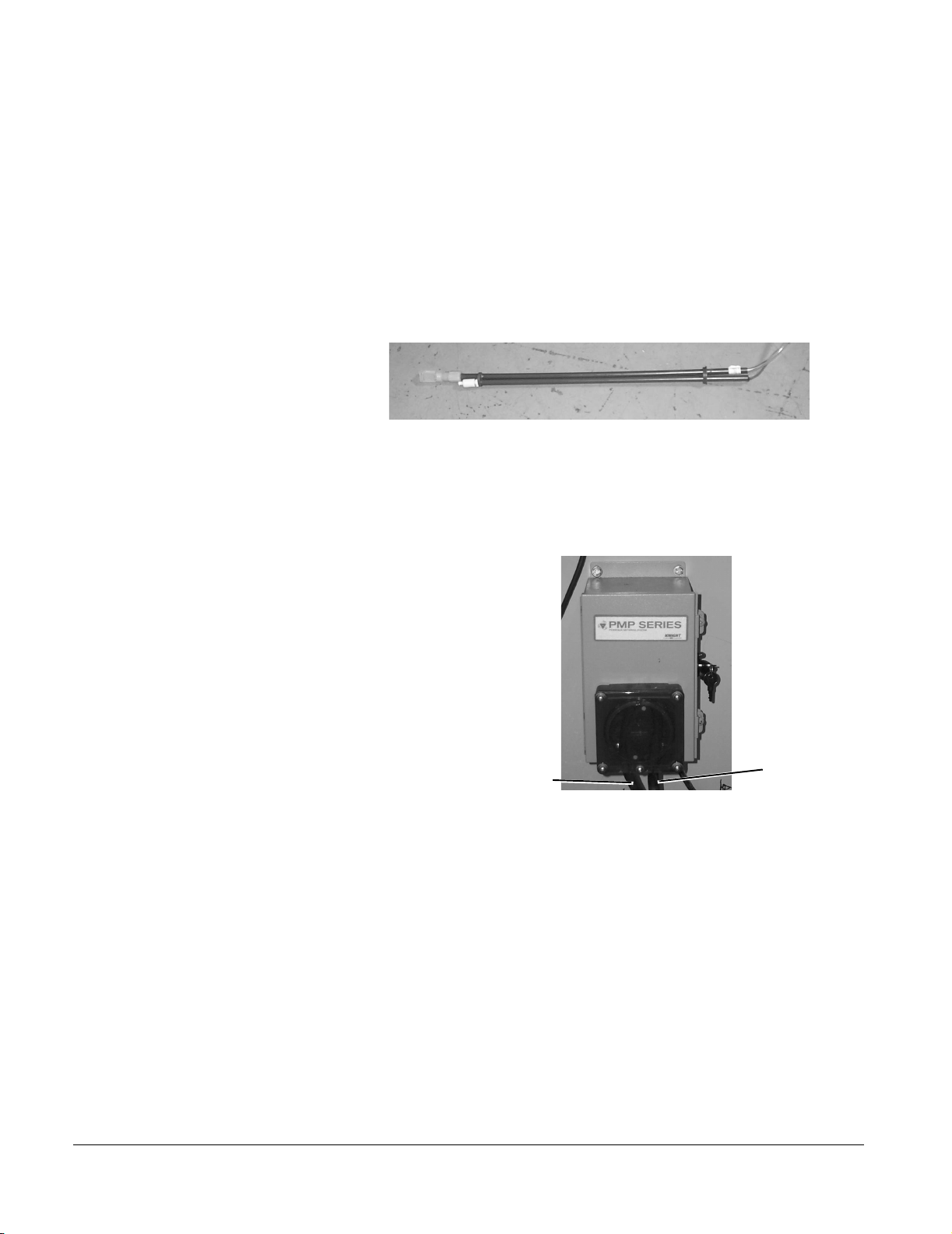
1. Connect the detergent tubing.
a. Place the detergent float switch assembly (see
Figure 2–34. Detergent/Rinse Aid Float Switch
b. Connect the supply tubing from the detergent float
Figure 2–34) in the detergent supply container.
switch to the left side of the detergent pump (Figure 2–
35).
Figure 2–35. Detergent Pump
TO DETERGENT SUPPLY
c. Connect the DETERGENT connector from the float
switch to the DETERGENT connector from the cable
connected to the float switch junction box.
d. Connect the discharge tubing to the right side of the
detergent pump.
e. Connect the plastic compression fitting on the other
end of the tubing to the fitting on the tank.
TO TANK
2–46
Page 61

7800A Series Floor Mounted Cart and Utensil Washer
2. Connect the rinse aid tubing.
a. Place the rinse aid float switch assembly in the rinse
aid supply container.
b. Connect the supply tubing from the float switch
assembly to the bottom plastic compression fitting on
the rinse aid pump (Figure 2–36).
Figure 2–36. Rinse Aid Pump
TO RINSE AID INJECTOR
TO RINSE AID SUPPLY
c. Connect the RINSE AID connector from the float
switch to the RINSE AID connector from the cable
connected to the float switch junction box.
d. Connect the discharge tubing to the top fitting on the
rinse aid pump using plastic compression fitting.
e. Slide the other end of the tubing over the barbed fitting
between the output of the booster heater and the
stainless steel piping to the rinse manifold.
Figure 2–37. Rinse Aid Injector Fitting
TO RINSE AID
PUMP
RINSE AID
CHECK VALVE
61301604981 2–47
Page 62

Installation
Barrier Flanges Objective
Attach the barrier flanges to the load and unload ends of the washer.
The following instructions apply to units with structural walls situated at both
the load and unload ends. Units with only one wall (generally at the unload
end) receive a service area enclosure and an unload end top barrier flange.
For the latter configuration, refer to “Service Area Enclosure (Option)” on
page 2-50.
NOTE
The method and materials for securing the barrier flanges to a structural
wall are to be provided by the customer.
Installation
Figure 2–38. Barrier Flanges
2–48
1. Using #10-32 fasteners, attach the two short attachment
angles to the load end side panel and the single long
attachment angle to the unload end side panel. Position
the proximity switch and unload end indicator panel cables
so they will route through the cutouts provided in the
angles.
Page 63

2. Secure the load and unload end side barrier flanges to the
attachment angles with #10-32 fasteners.
The interior edge of a flange seats between an angle and
the side panel.
3. Attach the top barrier flanges.
a. Remove and retain the acorn nut fasteners from the
b. Attach the load and unload end top barrier flanges.
c. Use the acorn nuts along with #10-32 fasteners to
4. For vented units only, attach the intake frame assembly to
the unload end top barrier flange.
Pit Covers Objective
Install the pit covers at the load and unload ends of a pit mounted washer.
7800A Series Floor Mounted Cart and Utensil Washer
two top thru bolts.
secure the flanges to the top panels and to the side
barrier flanges.
Installation
1. Place the pit cover in position against the washer.
2. Using the mounting holes in the cover flanges as a
template, drill and tap #10-32 holes into the washer base.
3. Secure the pit cover to the washer base with #10-32
fasteners.
4. Repeat steps 1 through 3 for the other cover.
61301604981 2–49
Page 64

Installation
Service Area Enclosure (Option)
Objective
Assemble the service area enclosure.
The service area enclosure is usually installed on units that do not have a
structural wall at either the load or unload end.
Installation
Refer to Figure 2–39. Service Area Enclosure.
Figure 2–39. Service Area Enclosure
2–50
1. Attach the two short attachment angles to the load end
side panel and the single long attachment angle to the
unload end side panel with #10-32 fasteners. Position the
proximity switch and unload end indicator panel cables so
they will route through the cutouts provided in the angles.
2. Use four 1/4-20 fasteners to attach the mounting base
frame to the base frame of the washer.
3. Secure the load and unload end side panels to the
attachment angles. The interior edge of a panel seats
between an angle and the washer’s side panel. Use #1032 fasteners to secure the base of the each panel to the
mounting base frame.
Page 65

4. Position the access panel divider on the mounting base
frame. The upper end of the divider has two #10-32
threaded holes and the lower end has two 1/4" diameter
holes. Secure the bottom of the divider to the frame with
two #10-32 fasteners.
5. Secure the top panel to the load and unload end side
panels. Use #10-32 fasteners to secure it to the top of the
access panel divider.
6. Install the service access panels.
a. Fit the holes in the bottom of a panel to the panel
b. Turn the latches 90 degrees to secure the service
7. Attach the load and unload end top barrier flanges.
Ramps Objective
7800A Series Floor Mounted Cart and Utensil Washer
mounting studs on the mounting base frame.
access panel in place.
NOTE
Install the ramps at the load and unload ends of a floor mounted washer.
This procedure applies only to floor mounted washers.
Installation
Refer to Figure 2–40. Ramp.
Figure 2–40. Ramp
Insert the 1" support flange of the ramp behind the front edge of the drip
trough that extends from the door threshold. No fasteners are required.
61301604981 2–51
Page 66

Installation
Exhaust Connection This procedure applies only to vented washers. Install a dedicated,
corrosion-proof, watertight duct (800 CFM, negative 1/4" static pressure)
from the 6 1/2" x 10" flanged exhaust assembly (Figure 2–21 on page 2–28)
to the building’s exhaust system. The duct assembly should be sloped
toward the washer.
Plumbing System Connections
Electrical Supply Connection
NOTE
All service connections must conform to local codes. The supply line
connections are labeled for identification. Refer to “Utilities and
Specifications” on page 1-2 for pipe sizes, pressures, and requirements at
site of installation.
1. Connect the 1-inch hot water supply line to the 3/4-inch
service connection.
2. Connect the 3/4-inch cold water supply line to the 3/4-inch
service connection.
3. Connect the 1-1/2 inch steam supply line to the 1-1/2 inch
service connection.
4. Connect the 3/4-inch steam return or drain line to the 3/4-
inch condensate line connection.
5. If the washer has the purified rinse option, connect the 3/4-
inch purified water supply line to the 3/4-inch service
connection.
The customer must install a fused disconnect in the electrical supply line. It
should be situated close to the unit for easy access by service personnel.
2–52
1. Route the electrical supply line through the top of the
control box to the power distribution block.
2. Connect the electrical supply line. Refer to “Utilities and
Specifications” on page 1-2.
Page 67

7800A Series Floor Mounted Cart and Utensil Washer
Concluding Tasks 1. Apply silicone sealant to all permanent exterior seams.
2. Remove the protective film from all exterior surfaces of the
washer.
3. Clean and polish the exterior surfaces of the washer.
4. Remove the cardboard protective flooring from inside the
washer.
5. Perform the steps in the Installation Checkout Procedure
included with your washer. Complete the SCR and return
both to Getinge USA service headquarters.
NOTE
At this point, installation is complete. You must contact Getinge USA
personnel to make mechanical adjustments and electrical performance
tests before the equipment is operated. Failure to do so before operation
voids the warranty.
61301604981 2–53
Page 68

Installation
2–54
Page 69

Section 3 Rough-In Drawings
Rough-in drawings for the pit mounted and floor mounted versions of the
7800A washer are included in the following pages.
61301604981 3–1
Page 70

Rough-In Drawings
Figure 3–1. 7800A Washer (HS4099, sheet 1 of 7)
3–2
Page 71

7800A Series Floor Mounted Cart and Utensil Washer
Figure 3–1. 7800A Washer (HS4099, sheet 2 of 7)
61301604981 3–3
Page 72

Rough-In Drawings
Figure 3–1. 7800A Washer (HS4099, sheet 3 of 7)
3–4
Page 73

7800A Series Floor Mounted Cart and Utensil Washer
Figure 3–1. 7800A Washer (HS4099, sheet 4 of 7)
61301604981 3–5
Page 74

Rough-In Drawings
Figure 3–1. 7800A Washer (HS4099, sheet 5 of 7)
3–6
Page 75

7800A Series Floor Mounted Cart and Utensil Washer
Figure 3–1. 7800A Washer (HS4099, sheet 6 of 7)
61301604981 3–7
Page 76

Rough-In Drawings
Figure 3–1. 7800A Washer (HS4099, sheet 7 of 7)
3–8
Page 77

Section 4 Seismic Anchoring Drawings
Seismic anchoring drawings for the 7800A washer are included in the
following pages.
61301604981 4–1
Page 78

Seismic Anchoring Drawings
Figure 4–1. 7800A Washer (700488, sheet 1 of 12)
121179
A
5/16/03
4–2
Page 79

7800A Series Floor Mounted Cart and Utensil Washer
Figure 4–1. 7800A Washer (700488, sheet 2 of 12)
A
121179
5/16/03
61301604981 4–3
Page 80

Seismic Anchoring Drawings
Figure 4–1. 7800A Washer (700488, sheet 3 of 12)
121179
A
5/16/03
4–4
Page 81

7800A Series Floor Mounted Cart and Utensil Washer
Figure 4–1. 7800A Washer (700488, sheet 4 of 12)
A 121179
5/
61301604981 4–5
Page 82

Seismic Anchoring Drawings
Figure 4–1. 7800A Washer (700488, sheet 5 of 12)
121179
A
5/16/03
4–6
Page 83

7800A Series Floor Mounted Cart and Utensil Washer
Figure 4–1. 7800A Washer (700488, sheet 6 of 12)
121179 5/16/03
A
61301604981 4–7
Page 84

Seismic Anchoring Drawings
Figure 4–1. 7800A Washer (700488, sheet 7 of 12
A
121179 5/16/03
4–8
Page 85

7800A Series Floor Mounted Cart and Utensil Washer
Figure 4–1. 7800A Washer (700488, sheet 8 of 12)
121179 5/16/03
A
61301604981 4–9
Page 86

Seismic Anchoring Drawings
7800A Washer (700488, sheet 9 of 12)
A 121179 5/16/03
4–10
Page 87

7800A Series Floor Mounted Cart and Utensil Washer
Figure 4–1. 7800A Washer (700488, sheet 10 of 12)
121179
A
5/16/03
61301604981 4–11
Page 88

Seismic Anchoring Drawings
Figure 4–1. 7800A Washer (700488, sheet 11 of 12)
A
121179 5/16/03
4–12
Page 89

7800A Series Floor Mounted Cart and Utensil Washer
Figure 4–1. 7800A Washer (700488, sheet 12 of 12)
A
121179
5/16/03
61301604981 4–13
Page 90

Seismic Anchoring Drawings
4–14
Page 91

Index
A
Actuator Assembly 2–25
B
Barrier Flanges 2–48
Base/Sump Assembly
2–1
C
Cables, Emergency Stop Switch 2–43
Chain Drive Assembly
Channel Fillers
Control Box
2–18
2–36
2–11
D
Dispenser Float Switch Junction Box 2–19
Dispenser Tubing
Door Assembly
Door Latch Retainers
Door Proximity Switches
Drive Chain Tension Idlers
Drive Motor Proximity Switch
Drive Motor Proximity Switch Collar
2–46
2–12, 2–45
2–13
2–23
2–35
2–37
2–17
E
Electrical Supply Connection 2–52
Electrical Wiring
Emergency Stop Switch
Emergency Stop Switch Cables
Exhaust Assembly
Exhaust Connection
2–32
2–21
2–43
2–28
2–52
F
Float Switch Junction Box 2–19
Floor Grates
Floor Mount Option
Floor Tilt Pulley System
2–2
1–3
2–25
G
General Description 1–1
Guard Tubes
2–41
H
Hinge Mounts 2–13
I
Idler Bearing 2–35
Installation Advisory
Installation Procedures
Barrier Flanges 2–48
Base/Sump Assembly
Chain Drive Assembly
Channel Fillers
Components on Inside of Washer
Components on Outside of Washer
Components on Top of Washer
Concluding Tasks
Control Box
Dispenser Float Switch Junction Box
Dispenser Tubing
Door Assembly
Door Proximity Switches
Drive Chain Tension Idlers and Idler Bearing
Electrical Supply Connection
Electrical Wiring
Emergency Stop Switch
Emergency Stop Switch Cables
Exhaust Assembly
Exhaust Connection
Final Door Assembly
Final Installation Tasks
Intake Assembly
Light Assembly
Manifold Cover, Manifold Guard Tubes, Wash Cart Tubes
1–3
2–1
2–36
2–11
2–35
2–14
2–24
2–53
2–18
2–19
2–46
2–12
2–23
2–35
2–52
2–32
2–21
2–43
2–28
2–52
2–45
2–44
2–29
2–16
Final Door Assembly 2–45
61301604981 I–1
Page 92

Index
2–41
Pit Covers
Plumbing System Connections
Power Floor Tilt Pulley System
Ramps
Return Pump
Service Area Enclosure
Spray Manifold Drive Motor
Spray Manifold Supports and Manifold Assembly
Threshold Assemblies
Transformer
Unload End Indicator Panel Box
Washer Panels
Washer Structure
Intake Assembly
2–49
2–52
2–25
2–51
2–15
2–50
2–17
2–11
2–27
2–22
2–5
2–1
2–29
J
Junction Box Cable Connections 2–33
L
Light Assembly 2–16
Load Length Option
Low Suction Collar
1–3
2–15
2–38
O
Options 1–3
P
Panels 2–5
Pit Covers
Pit Mount Option
Pit Mounted Washer, Rough-in Drawing
Plumbing
Plumbing System Connections
Power Floor Tilt Pulley System
Printer Option
Proximity Switch Collar, Drive Motor
Proximity Switch, Drive Motor
Proximity Switches, Door
Pulley Mounts
Pump, Return
Purified Water Rinse Option
Push Rod/Chain Assemblies
2–49
1–3
2–30
2–52
2–25
1–4
2–17
2–37
2–23
2–26
2–15
1–4
2–36
3–2
M
Manifold Assembly 2–38
Manifold Cover
Manifold Drive Motor
Manifold Guard Tubes
Manifold Supports
Materials and Tools Required
Model 78003 Slab on Grade, Seismic Anchoring
Model 78003 Upper Floor, Seismic Anchoring
Model 78004 Slab on Grade, Seismic Anchoring
Model 78004 Upper Floor, Seismic Anchoring
Model 78005 Slab on Grade, Seismic Anchoring
Model 78005 Upper Floor, Seismic Anchoring
Model Identification
2–41
2–17
2–41
2–38
1–5
4–4, 4–5
4–8, 4–9
4–12, 4–13
1–2
N
Non-vented Option 1–4
4–2, 4–3
4–6, 4–7
4–10, 4–11
R
Ramps 2–51
Rating Plate
Return Pump
Rough-In Drawings
1–2
2–15
3–1, 4–1
S
Seismic Anchoring 2–2
Service Area Enclosure
Service Enclosure Option
Shipping Configuration
Size Option
Solenoid Valve Assembly
Spray Manifold Assembly
Spray Manifold Drive Motor
Spray Manifold Supports
Sump/Base Assembly
1–3
2–50
1–4
2–38
2–1
1–3
2–32
2–38
2–17
I–2
Page 93

7800A Series Floor Mounted Cart and Utensil Washer
T
Tension Idlers 2–35
Threshold Assemblies
Tools and Materials Required
Track/Frame Assembly
Transformer
Tubing, Dispenser
2–27
2–11
1–5
2–2
2–46
U
Unload End Indicator Panel Box 2–22
Utilities and Specifications
V
Vented Option 1–4
W
Wash Cart Tubes 2–41
Washer Options
Washer Panels
Washer Structure
Wiring, Electrical
1–3
2–5
2–1
2–32
1–2
61301604981
Page 94

Index
I–4
Page 95

Page 96

Getinge USA, Inc.
1777 East Henrietta Road
Telephone (800) 950–9912 Rochester, New York 14623–3133 USA Facsimile (800) 950–2570
 Loading...