

Page 1
FILE CREATED: 5/98
EXIT MANUAL
Click here to
Click here to
EXIT Manual
EXIT Manual
Information contained herein is applicable to
units manufactured between 1/97 and 5/98.
Previous/future units may vary.
Page 2
OWNER and OPERATOR MANUAL 350527 (5/16/96)
Rev. B (1/1/97) General Revision: Getinge/Castle
DESCRIPTION OF SYMBOLS & NOTES IN MANUAL
The following symbols with related notes appear in this manual.
”Warning” notes alert the user to the possibility of personal injury.
”Caution” notes alert the user to the possibility of damage to the equipment.
EXIT MANUAL
“Notes” alert the user to pertinent facts and conditions.
This manual contains proprietary information of Getinge/Castle, Inc. It shall not be reproduced in
whole or in part without the written permission of Getinge/Castle.
®
GETINGE and CASTLE are registered trademarks.
Copyright © 1997 by Getinge/Castle, Inc.
ii 350527
Page 3

EXIT MANUAL
Table Of Contents
1. General Description ................................................................................................ 1-1
Introduction ........................................................................................................................................ 1-1
Exterior Components ......................................................................................................................... 1-2
Chamber Components ....................................................................................................................... 1-4
Processing Cycle Description ............................................................................................................ 1-6
2. Microprocessor Controller ..................................................................................... 2-1
Description ........................................................................................................................................2-1
Keep Record of Cycle Settings .......................................................................................................... 2-2
To Change Cycle Phase Settings ...................................................................................................... 2-3
Speed Scrolling Numerical Values ..................................................................................................... 2-5
3. Operating Instructions ............................................................................................ 3-1
Prior To Routine Operation ...............................................................................................................3-1
Power On-Power Off/Reset .............................................................................................................. 3-1
Routine Operation; Detail ..................................................................................................................3-1
Stop - Using the Stop Function Key ................................................................................................... 3-3
Stop - Using the Power On-Off/Reset Switch .................................................................................... 3-4
Overflow Mode ..................................................................................................................................3-4
Miscellaneous .................................................................................................................................... 3-5
4. Maintenance ............................................................................................................. 4-1
Appendix A: Loading/Accessories ........................................................................... A-1
350527
iii
Page 4

GENERAL DESCRIPTION
INTRODUCTION
EXIT MANUAL
7620 WASHER
1. General Description
The Castle 7620 Washer is a compact unit designed
to clean surgical instruments, laboratory glassware,
metalware and utensils. It may be installed on a work
counter, under a counter, or on a freestanding base
cabinet.
The unit features a 20"W x 20"D x 15"H load area
within its wash chamber. A fixed track assembly and
a removable grid are provided as standard
equipment. When in position, the grid will support a
20" x 20" (or smaller) utensil basket, instrument tray,
or assorted loose items. With the grid removed, the
fixed track assembly will support a compatible roll-out
basket grid, or various sized Spindle Headers.
Wash and rinse spray treatments are provided by
means of two spinning manifolds, one located above
and one below the load area. When used, a Spindle
Header coupled directly to the high pressure
plumbing system effectively subjects the interior of
ware to the wash and rinse spray treatments.
Processing cycles are controlled by a programmable
microprocessor-based controller that will store four
pre-programmed cycles. The operator needs only to
select and start an appropriate cycle.
Standard cycle phases provide for a Prewash, a
Wash, and two successive tap water Rinse
treatments followed by a third and final Rinse of
purified water (DI). As an optional treatment,
instrument lubricant (MILK) may be incorporated into
the final Rinse.
All treatment solutions are used once and drained.
350527
FIGURE 1-1: CASTLE 7620 WASHER
1-1
Page 5

7620 WASHER
1. General Description
EXTERIOR COMPONENTS
(Ref: Figure 1-2)
EXIT MANUAL
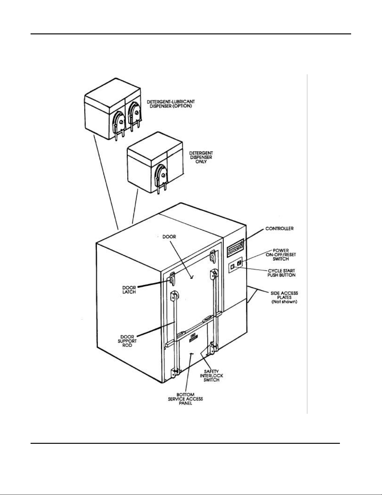
Power ON-OFF/RESET Switch
Activates and deactivates the Washer
controls. A green light will illuminate the
switch when it is in the ON position.
Cycle START Push Button
Starts the processing cycle when pressed.
Controller
Microprocessor-based controller that features
an LCD message screen, six Function and
two Selector Keys. Refer to 2.
Microprocessor Controller on page 2-1 for a
detailed description of this component.
Access Plates: Side (Upper & Lower)
Permits access to the interior components
located behind and beneath the Washer
controls.
Service Access Panel: Bottom
Permits access to the interior components
located beneath the Washer chamber.
Door
Opens at the top. Hinged at the bottom.
Lowers to the horizontal position for access
to the Washer chamber.
Safety Interlock Switch
Stops all machine functions if the door is
opened during Washer operation.
Door Latch
Secures the door in the closed position. Two
manually operated latches are provided.
Door Support Rod
Supports the door when it is lowered to the
horizontal position. One rod is attached to
each side of the door.
Detergent Dispenser
Automatically dispenses detergent into the
reservoir tank at the start of the Wash phase
of the processing cycle. This Dispenser may
be remotely located or mounted to the back
of the unit.
Detergent-Lubricant Dispenser(Option)
Automatically dispenses detergent into the
reservoir tank at the start of the Wash phase
of the processing cycle. An additional pump
automatically dispenses instrument lubricant
(Option) into the rinse water supply line at the
start of the final Rinse (DI) phase of the
processing cycle. This Dispenser may be
remotely located or mounted to the back of
the unit.
1-2
350527
Page 6
EXIT MANUAL
7620 WASHER
1. General Description
350527
FIGURE 1-1: EXTERIOR COMPONENTS
1-3
Page 7

7620 WASHER
1. General Description
CHAMBER COMPONENTS
(See Figure: 1- 3)
EXIT MANUAL
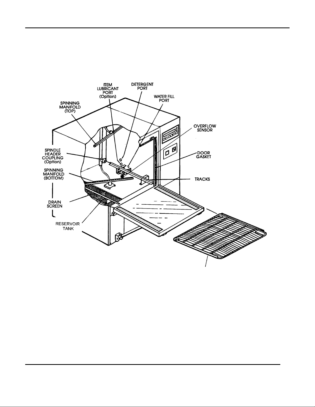
Spinning Manifold: Top
Delivers a rotary spray of detergent and rinse
water down over the load.
Spinning Manifold: Bottom
Delivers a rotary spray of detergent and rinse
water up against the load.
Spindle Header Coupling (Option)
Enables the connection of hollow tube
Spindle Headers to the detergent and rinse
water plumbing system for the purpose of
subjecting the interior of ware to processing
treatments. When Headers are not used a
check valve within the Coupling automatically
closes so that pressurized treatments are
delivered through the spinning manifolds
only.
Water Fill Port
Point at which the fresh water supply empties
into the chamber for the purpose of filling the
Reservoir Tank.
Detergent Port
Point at which the liquid detergent is
dispensed into the chamber.
Drain Screen
Prevents large particles of foreign matter
from being carried into the Reservoir Tank.
The Screen can be removed by hand.
Door Gasket
Provides a door-to-chamber seal when the
door is in the closed position.
Bottom Grid
A removable support designed to hold an
instrument tray, basket, or loose items during
Washer operation.
Tracks
Support the Bottom Grid. When the Grid is
removed, the Tracks will accept a Spindle
Header, or compatible roll-out Grid.
Overflow Sensor
Turns on the Washer's drain pump should
one or more of the system's water fill
components fail and an overflow condition
result. See also: OVERFLOW MODE, page
3-6.
Item Lubricant Port (Option)
Point at which the item lubricant (Milk) is
dispensed into the chamber - when that
option is provided.
Reservoir Tank
Alternately holds the detergent and rinse
water supplies during a processing cycle.
Capacity: 2-1/2 gallons.
1-4
350527
Page 8
EXIT MANUAL
7620 WASHER
1. General Description
350527
FIGURE 1-3: CHAMBER COMPONENTS
1-5
Page 9

7620 WASHER
1. General Description
PROCESSING CYCLE DESCRIPTION
EXIT MANUAL
The following is a description of the cycle phases
available with the 7620 Washer, in the order in which
they are programmed to function.
Prewash
Reservoir tank is filled with cold water. When
tank is full, phase timing starts. Load is
subjected to a recirculated, unheated water
spray for the purpose of removing as much
soil as possible prior to the use of the Alkali
Wash detergent. When timing ends, the
reservoir tank is drained. (Use of hot water
instead of cold may be provided as an
option.)
The duration of this phase (0 - 600 seconds)
is programmed at the Controller.
Wash
Reservoir tank is refilled with heated water.
Phase timing starts - detergent is
automatically dispensed into the tank. Load
is subjected to a recirculated detergent
solution spray for the purpose of
loosening/removing any soil that remains
following the Prewash phase. Solution
temperature is maintained by the reservoir
heating system. When timing ends, the
reservoir tank is drained.
Rinse-2
Reservoir tank is refilled with hot water.
Phase timing starts. Load is subjected to a
second recirculated rinse water spray for the
purpose of removing any residue of detergent
solution and loosened soil. Water
temperature is maintained by the reservoir
heating system. When timing ends, the
reservoir tank is drained.
The duration of this phase (0 - 600 seconds)
and water temperature (140-180 degrees F)
are programmed at the Controller.
Final Rinse
Reservoir tank is refilled with purified (DI)
water. Phase timing starts. Load is
subjected to a recirculated purified water
spray for the purpose of removing any rinse
water contaminants. Water temperature is
maintained by the reservoir heating system.
If water temperature should drop below
setpoint, timing will be suspended until the
water is heated back to setpoint. When
timing ends, the reservoir tank is drained.
The duration of this phase (60 - 600 seconds)
and water temperature (140-180 degrees F)
are programmed at the Controller.
Rinse-1
1-6
The duration of this phase (120 - 600
seconds) and solution temperature (140-180
degrees F) are programmed at the Controller.
Reservoir tank is refilled with hot water.
Phase timing starts. Load is subjected to a
recirculated rinse water spray for the purpose
of removing any residue of detergent solution
and loosened soil. Water temperature is not
maintained by the reservoir heating system.
When timing ends, the reservoir tank is
drained.
The duration of this phase (0 - 600 seconds)
is programmed at the Controller.
Final Rinse Options:
• Water supply may be tap water instead of purified
water.
• Instrument Lubricant may be dispensed into the
recirculating rinse water. This would occur during
the final 20 seconds (recommended) of the
phase.
Cooling
Washer stands idle for a 30-second period of
draining and cooling.
A processing cycle will end and the
alarm will sound at the conclusion of
Cooling.
350527
Page 10

MICROPROCESSOR CONTROLLER
DESCRIPTION
EXIT MANUAL
7620 WASHER
2. Microprocessor Controller
STOP Function Key
Terminates an ongoing cycle in the event of
an emergency or any other situation that may
require bringing operation of the Washer to
an immediate halt. (See also: STOP, page 3-
5.)
DRAIN Function Key
Manually drains the contents of the reservoir
tank. Used primarily by service/maintenance
personnel (eg: To ensure the tank is empty
before control power is turned off.).
CYCLE SELECT Function Key
Selects the desired preset processing cycle
that is to be run on the Washer. Four
selections are available (1, 2, 3, 4).
SETUP Function Key
Used to access the selectable cycle phase
settings for viewing or programming
purposes.
ENTER Function Key
Used to enter changes to a cycle phase's
selectable settings.
FIGURE 2-1: MICROPROCESSOR CONTROLLER
MODIFY Function Key
Used to designate a position where data is to
be entered. Function is similar to that of a
cursor.
Up Selector
Used to scroll in an upward direction through
available selections and numerical values.
Down Selector
Used to scroll in a downward direction
through available selections and numerical
values.
LCD Message Screen
Shows pertinent information in a 2-line Liquid
Crystal Display (LCD). Routine information
includes cycle selection, cycle phase
identification and timing, reservoir tank
temperature, etc.
Buzzer
Sounds an intermittent alert at the conclusion
of a processing cycle. Shuts off when the
Washer door is opened.
350527
2-1
Page 11

7620 WASHER
2. Microprocessor Controller
KEEP RECORD OF CYCLE SETTINGS
EXIT MANUAL
The Microprocessor Controller offers the operator a
selection of four preprogrammed cycles (1, 2, 3, 4).
Included in the program for each cycle are
time/temperature settings that control the processing
phases.
It is suggested that a record of these settings be
maintained for quick reference.
CYCLE SETTINGS
7620 Washer ID #:
SETTING DESCRIPTION CYCLE 1 CYCLE 2 CYCLE 3 CYCLE4
PREWASH
(hot or cold)
PREWASH TIME
(seconds)
To view the settings for a particular cycle, 1)
select that cycle by pressing the Cycle Select
Function Key, then 2) press the Setup Function
Key, then 3) scroll through the settings using the
Up or Down Selector.
The following chart format has been provided for the
purpose of recording cycle settings.
WASH
(seconds/degrees F)
RINSE 1 TIME
(seconds/degrees F)
RINSE 2
(seconds/degrees F)
LUBRICANT
(on or off)
FINAL RINSE
(seconds/degrees F)
2-2
350527
Page 12

TO CHANGE CYCLE PHASE SETTINGS
EXIT MANUAL
7620 WASHER
2. Microprocessor Controller
To change any one, or all, of the selectable cycle
phase settings for a particular cycle:
1. Select the cycle (1, 2, 3, or 4) by pressing the
Cycle Select Function Key.
2. Press the Setup Function Key to access the cycle
phase settings for the cycle that was selected in
Step 1.
The first programmable setting will be displayed.
CYCLE 1 PREWASH
0 COLD
The top line identifies the cycle and the cycle's
phase. The bottom line is the programmable
setting. In this case it may be either 0 COLD or 1
HOT, depending on the type of water supply
desired for use in the Prewash phase.
To change from Cold to Hot, press the Modify
Function Key: the numerical designator "0" (zero)
will start flashing. Then press the Up Selector:
the bottom line display will change to "1 HOT".
Finally, press the Enter Function Key to enter the
change - or - do nothing, the change will be
entered automatically when the flashing stops (in
15 seconds).
3. Press the Up Selector to scroll the display to the
next cycle phase setting.
CYCLE 1 PREWASH
TIME xxx sec
Time Range: 0 - 600 seconds.
The top line identifies the cycle and the cycle's
phase. The bottom line is the current setting for
Prewash phase timing, in seconds. (If no change
is desired, press the Up Selector to advance to
the next display.)
To change the value, press the Modify Function
Key: the current numerical value "xxx" will start
flashing. Press the Up or Down Selector as
required until the desired value appears. Then,
press the Enter Function Key.
To exit the program at this point, press the Setup
Function Key, otherwise proceed with Step 4.
4. Press the Up Selector to scroll the display to the
next cycle phase setting.
CYCLE 1 WASH
xxx sec xxx F
To change from Hot to Cold, press the Modify
Function Key: the numerical designator "1" will
start flashing. Then press the Down Selector: the
bottom line display will change to "0 COLD".
Finally, press the Enter Function Key to enter the
change - or - do nothing, the change will be
entered automatically when the flashing stops (in
15 seconds).
To exit the program at this point, press the Setup
Function Key, otherwise proceed with Step 3.
350527
Time Range: 120 - 600 seconds
Temp Range: 140 - 180 degrees F
The top line identifies the cycle and the cycle's
phase. The bottom line displays the current
settings for Wash phase timing (in seconds) and
temperature (in degrees F). (If no change is
desired, press the Up Selector to advance to the
next display.)
To change the first value, press the Modify
Function Key: the current numerical value "xxx"
for seconds will start flashing. (If no change is
desired, press the Modify Function Key again to
switch to the current numerical value "xxx' for
degrees F.)
2-3
Page 13

7620 WASHER
2. Microprocessor Controller
EXIT MANUAL
Press the Up or Down Selector as required until
the desired value appears. Then, press the Enter
Function Key.
To change the second value, press the Modify
Function Key: the current numerical value "xxx"
for degrees F will start flashing. Press the Up or
Down Selector as required until the desired value
appears. Then, press the Enter Function Key.
To exit the program at this point, press the Setup
Function Key, otherwise proceed with Step 5.
5. Press the Up Selector to scroll the display to the
next cycle phase setting.
CYCLE 1 RINSE 1
TIME xxx sec
Time Range: 0 - 600 seconds
The top line identifies the phase and the cycle.
The bottom line is the current setting for Rinse 1
phase timing, in seconds. (If no change is
desired, press the Up Selector to advance to the
next display.)
To change the value, press the Modify Function
Key: the current numerical value "xxx" will start
flashing. Press the Up or Down Selector as
required until the desired value appears. Then,
press the Enter Function Key.
To exit the program at this point, press the Setup
Function Key, otherwise proceed with Step 6.
6. Press the Up Selector to scroll the display to the
next cycle phase setting.
The top line identifies the cycle and the cycle's
phase. The bottom line displays the current
settings for Rinse 2 phase timing (in seconds)
and temperature (in degrees F). (If no change is
desired, press the Up Selector to advance to the
next display.)
To change the first value, press the Modify
Function Key: the current numerical value "xxx"
for seconds will start flashing. (If no change is
desired, press the Modify Function Key again to
switch to the current numerical value "xxx" for
degrees F.)
Press the Up or Down Selector as required until
the desired value appears. Then, press the Enter
Function Key.
To change the second value, press the Modify
Function Key: the current numerical value "xxx"
for degrees F will start flashing. Press the Up or
Down Selector as required until the desired value
appears. Then, press the Enter Function Key.
To exit the program at this point, press the Setup
Function Key, otherwise proceed with Step 7.
7. Press the Up Selector to scroll the display to the
final cycle phase setting.
CYCLE 1 FINAL RINSE
xxx sec xxx F
Time Range: 60 - 600 seconds
Temp Range: 140 - 180 degrees F
The top line identifies the cycle and the cycle's
phase. The bottom line displays the current
settings for Final Rinse phase timing (in seconds)
and temperature (in degrees F).
CYCLE 1 RINSE 2
xxx sec xxx F
Time Range: 0 - 600 seconds
Temp Range: 140 - 180 degrees F
2-4
To change the first value, press the Modify
Function Key: the current numerical value "xxx"
for seconds will start flashing. (If no change is
desired, press the Modify Function Key again to
switch to the current numerical value "xxx' for
degrees F.)
Press the Up or Down Selector as required until
the desired value appears. Then, press the Enter
Function Key.
350527
Page 14

EXIT MANUAL
7620 WASHER
2. Microprocessor Controller
To change the second value, press the Modify
Function Key: the current numerical value "xxx"
for degrees F will start flashing. Press the Up or
Down Selector as required until the desired value
appears. Then, press the Enter Function Key.
To exit the program at this point, press the Setup
Function Key, otherwise proceed with Step 8.
8. Press the Up Selector to scroll the display to the
optional portion of the final cycle phase setting.
The top line identifies the cycle and the item
lubrication portion of the Final Rinse phase of that
cycle. The bottom line is the current ON/OFF
setting for the item lubrication dispenser. In this
case it may be either “0 OFF" or "1 ON". (If no
change is desired, press the Up Selector to
advance to the next display.)
To change from OFF to ON, press the Modify
Function Key: the numerical designator "0" (zero)
will start flashing. Then press the Up Selector:
the bottom line display will change to "1 ON".
Then, press the Enter Function Key.
9. Exit the program by pressing the Setup Function
Key.
Repeat Steps 1 and 2, if desired, to access the
remaining three cycle programs.
SPEED SCROLLING NUMERICAL VALUES
Holding the MODIFY Function Key depressed while
manipulating an UP or DOWN Selector Key will
enable the operator to scroll through numbers at a far
greater speed than can be obtained by using a
Selector Key alone.
To change from ON to OFF, press the Modify
Function Key: the numerical designator "1" will
start flashing. Then press the Down Selector: the
bottom line display will change to "0 OFF". Then,
press the Enter Function Key.
At this point all the selectable cycle phase settings
have been displayed. Pressing the Up Selector one
more time will bring up the Service Program Access
display.
SERVICE 1
Use of this program is restricted to qualified service
personnel only. Pressing the UP Selector again will
bring up the Continuous Wash display.
CONT. WASH 0 OFF
xxxx sec XXX ºF
This display is employed in the monthly maintenance
procedure for descaling the Washer's recirculation
system. See page 4-1.
350527
2-5
Page 15

OPERATING INSTRUCTIONS
EXIT MANUAL
7620 WASHER
3. Operating Instructions
PRIOR TO ROUTINE OPERATION
Always make sure a sufficient supply of detergent is
available for the Detergent Dispenser before turning
the Washer ON. Also, make sure the Dispenser's
supply tube is properly inserted into its detergent
supply container. (The same instruction would apply
to an item lubricant supply system if that option is
provided.)
POWER ON - POWER OFF/RESET
Switching the POWER ON-OFF/RESET Switch to
ON will turn on the Washer.
• The POWER ON-OFF/RESET Switch will light
(green).
• The Controller will come on. The following
message will be displayed on the Message
Screen.
READY TO LOAD
CYCLE X SELECTED
2. Load material into the Washer.
(See also: Appendix A: Loading/Accessories)
3. Close and secure the door.
The following message will appear:
PRESS START
CYCLE X SELECTED
4. Check/Change the cycle selection.
Current cycle selection (1,2,3, or 4) is displayed in
the bottom line of the message.
Press the Cycle Select Function Key to change
the cycle selection, if desired.
5. Press the Cycle START Push Button.
The reservoir tank will begin to fill.
The following message will appear:
FILLING TANK
ROUTINE OPERATION: DETAIL
Instructions carried here apply to the daily operation
of a Castle 7620 Washer. It assumes that the unit
has been properly installed and pre-tested: that the
chamber is clean, all four CYCLE selections are
programmed, the detergent supply is set up, any
optional equipment is ready for operation, etc.
1. Turn the POWER ON-OFF/RESET Switch to ON.
The following display will appear on the Controller's
message screen:
READY TO LOAD
CYCLE X SELECTED
350527
When the reservoir tank is full, the Prewash phase
will start and the following message will appear:
CYCLE X PREWASH
TIME XXX sec
The top line identifies the selected cycle and the cycle
phase that is currently running. The bottom line
displays the time remaining in the cycle phase.
3-1
Page 16

7620 WASHER
3. Operating Instructions
EXIT MANUAL
At the conclusion of the Prewash phase the following
message will appear:
DRAINING TANK
When the reservoir tank is empty the following
message will appear:
FILLING TANK
The reservoir tank will be refilled for the Wash phase
of the processing cycle.
As the cycle progresses to completion, the following
messages will appear:
CYCLE X WASH
XXX sec XXX ºF
(Time and Temperature displayed)
CYCLE X RINSE 2
XXX sec XXX ºF
(Time and Temperature displayed)
DRAINING TANK
FILLING TANK
CYCLE X FINAL RINSE
XXX sec XXX ºF
(Time and Temperature displayed)
DRAINING TANK
COOLING
PLEASE WAIT
DRAINING TANK
FILLING TANK
CYCLE X RINSE 1
XXX sec XXX ºF
(Time and Temperature displayed)
DRAINING TANK
FILLING TANK
Upon conclusion of the preset 30-second Cooling
phase, an intermittent buzzer will alert personnel the
cycle is complete.
The following message will appear:
CYCLE COMPLETE
READY TO UNLOAD
6. Open the door and unload the Washer.
When the door is opened the buzzer will stop and
the following message will be displayed:
READY TO LOAD
CYCLE X SELECTED
3-2
350527
Page 17

EXIT MANUAL
7620 WASHER
3. Operating Instructions
When the door is closed (whether the load has
been removed or not), the following message will
appear indicating that the unit is ready to run the
next processing cycle.
PRESS START
CYCLE X SELECTED
To run the same cycle again, press the Cycle START
Push Button.
To run a different cycle, use the Cycle Select
Function Key to select Cycle 1,2,3, or 4, then press
the Cycle START Push Button.
To discontinue operation, turn the POWER ONOFF/RESET Switch to OFF.
STOP (Using The Stop Function Key)
Pressing the Stop Function Key will immediately
terminate a processing cycle. The following message
will appear:
PRESS START
CYCLE X SELECTED
Depending on the nature of the situation that led to
the use of the STOP Function Key, the operator may
now (1) restart the washer, or (2) discontinue washer
operation.
To Restart The Washer: Press the START Push
Button.
• The reservoir tank will be drained automatically.
• After draining, the selected cycle will start.
(NOTE: A cycle will only start when the reservoir
tank is empty.)
To Discontinue Washer Operation: Press the
DRAIN Function Key to drain the reservoir tank. After
draining, turn the POWER ON-OFF/RESET Switch
to OFF.
350527
3-3
Page 18

7620 WASHER
3. Operating Instructions
EXIT MANUAL
STOP (Using The POWER ONOFF/RESET Switch)
This procedure is not presented as an
alternative to the STOP Function Key.
It should only be employed if
circumstances prohibit use of the
STOP Function Key.
Turning the POWER ON-OFF/RESET Switch to OFF
will immediately terminate a processing cycle. After
termination, the Switch should be turned back to the
ON position.
Depending on the situation that led to termination, the
operator may now (1) restart the washer, or (2)
discontinue washer operation.
To Restart The Washer: Press the START Push
Button.
• The reservoir tank will be drained automatically.
• After draining, the selected cycle will start.
(NOTE: A cycle will only start when the reservoir
tank is empty.)
To Discontinue Washer Operation: Press the
DRAIN Function Key to drain the reservoir tank. After
draining, turn the POWER ON-OFF/RESET Switch
back to OFF.
OVERFLOW MODE
In the event that a solenoid or a reservoir tank level
sensor malfunctions during one of the water fill
periods of a cycle, a condition could result in which
water overflows the reservoir tank and begins to fill
the chamber. Should this occur, the rising water will
be detected by the Overflow Sensor. Once detected,
an alarm will sound, the Washer's drain pump will be
turned on, and the following display will appear:
OVERFLOW MODE
CHECK FLOATS / VLV
Water will then be discharged through the drain
system until the water level reaches the low level
sensor in the reservoir tank. At that point, the alarm
will shut off and the Washer will attempt to restart the
"FILLING" stage of the phase.
FILLING TANK
If the attempt fails and the overflow condition reoccurs, the Washer will go back into the
"OVERFLOW MODE". Water will again be
discharged until the low level sensor is reached. The
Washer will then attempt to restart the cycle once
more.
The Washer will continue discharging and refilling in
an attempt at self-correction for a period of three (3)
minutes. Following this period, if the overflow
condition persists, the unit will shut down (The alarm
will continue to sound.).
3-4
The operator should then:
6. Press the STOP Function Key (The alarm will
shut off.)
7. Press the DRAIN Function Key to ensure the
chamber and reservoir tank are empty.
8. Discontinue Washer operation and notify qualified
service personnel.
If desired, the operator may
discontinue Washer operation at any
time during a ongoing OVERFLOW
MODE by pressing the STOP
Function Key.
350527
Page 19

MISCELLANEOUS
• If a door is unlatched during a cycle, the cycle will
be automatically terminated. The cycle may then
be restarted from the beginning (by pressing the
START Function Key) when the door is once
again closed and secure.
• All the Function and Selector Keys will be
inoperative during a processing cycle, except for
the STOP Function Key.
EXIT MANUAL
7620 WASHER
3. Operating Instructions
350527
3-5
Page 20

MAINTENANCE
EXIT MANUAL
7620 WASHER
4. Maintenance
DAILY
INSPECT-CLEAN
Inspect exterior and interior surfaces of the Washer.
Clean with mild detergent and a soft, damp cloth.
Give particular attention to the Drain Screen and the
screen surrounding the water fill port.
CHECK LIQUID SUPPLIES
Check the Wash detergent supply container. Refill or
replace if required.
Check the Instrument Lubricant supply container if
the unit is equipped for that option. Refill or replace if
required.
MONTHLY
DESCALE RECIRCULATION SYSTEM
Descaling the recirculation system prevents a buildup
of mineral deposits on the reservoir tank, heating
coils, etc. The procedure involves:
A. Removal and cleaning of the two Spinning
Manifolds.
B. Treating the recirculation system with a descaling
agent.
Contact your Castle service
representative for an appropriate
scale remover - and follow directions
for its use.
Procedure: Spinning Manifolds
1. Remove the two Spinning Manifold Assemblies
from the Washer chamber. Each is secured to its
plumbing fitting by means of a 3/4-18 Hex Head
Bearing Housing.
2. Disassemble the two 5/16-18 Hex Head Screws
from the ends of each Spinning Manifold
Assembly.
3. Flush the interiors of the Assemblies to remove
any accumulations of fine debris. Check the
3/32" diameter spray holes to ensure they are
unrestricted.
4. Reassemble the Spinning Manifold Assemblies to
their plumbing fittings. Do not reassemble the
Hex Head Screws to the ends of the manifolds at
this time.
350527
Procedure: Descale Recirculation System
1. Remove the drain screen from the chamber.
Clean if required, and set aside. Close Washer
door.
4-1
Page 21

7620 WASHER
4. Maintenance
EXIT MANUAL
2. Ready a graduated container with the correct
amount of descaler to be used per the descaler
manufacturer's specifications. (Ref: Reservoir
Tank Capacity =2-1/2 gallons)
3. Select any cycle.
PRESS START
CYCLE X SELECTED
4. Press the SETUP Function Key to access the
cycle phase settings.
5. Press the DOWN Selector once to bring up the
Continuous Wash display.
CONT. WASH 0 OFF
XXXX sec xxxºF
Time Range: 30 - 9999 seconds
Temp Range: 120 - 180 degrees F
6. Press the MODIFY Function Key twice (press wait - press) to designate the seconds value for
change. Then press the UP Selector as required
to set the correct duration for circulation of the
descaling solution.
DO NOT PRESS THE ENTER FUNCTION KEY
AT THIS TIME.
10. Open the door. Add the required amount of
descaler to the Reservoir Tank. Then, close the
door.
The Washer will fill for approximately 30 seconds.
If the door is not closed again within this period
the Washer will automatically drain the contents
of the reservoir tank. This would then necessitate
restarting the procedure from the beginning.
After "FILLING TANK" the following displays will
appear as the Continuous Wash cycle
progresses to completion.
CONTINUOUS WASH
XXXX sec xxxºF
(Time and Temperature displayed)
DRAINING TANK
COOLING
PLEASE WAIT
Upon conclusion of the preset 30-second Cooling
phase, an intermittent buzzer will sound.
The following message will appear:
7. Press the MODIFY Function Key again to
designate the temperature value for change.
Then press the UP Selector as required until the
correct temperature setpoint appears.
DO NOT PRESS THE ENTER FUNCTION KEY
AT THIS TIME.
8. Press the MODIFY Function Key again to move
back to the "0 OFF" segment of the display.
Then press the UP Selector once to switch the
Continuous Wash to "1 ON".
9. Press the ENTER Function Key to begin the
continuous wash. Filling will begin.
FILLING TANK
4-2
CYCLE COMPLETE
READY TO UNLOAD
11. Open the door. The following message will
appear:
READY TO LOAD
CYCLE X SELECTED
12. Close the door. The following message will
reappear:
350527
Page 22

The descaling cycle is complete, and the Washer is
now ready to run one or more Continuous Wash
flushing cycle to purge residual descaler from the
system.
To run a Continuous Wash flushing cycle repeat
the entire procedure described above, minus Step
10.
After the final flush, reassemble the 5/16" Hex Head
Screws to the ends of the Spinning Manifolds.
CHECK DISPENSER PUMP/TUBES
Check the Pump rollers and the supply tubing on the
Wash detergent dispenser, and the optional
Instrument Lubricant dispenser (if equipped). If
components show evidence of wear, notify qualified
service personnel for replacement.
EXIT MANUAL
7620 WASHER
4. Maintenance
EVERY 6 MONTHS
CHECK-CLEAN ALL Y-STRAINERS
Check the filter screens in all plumbing supply lines.
Clean if required. Task should be performed by
qualified service personnel.
350527
4-3
Page 23

APPENDIX A: LOADING/ACCESSORIES
EXIT MANUAL
7620 WASHER
Appendix A
The information presented in this Appendix is
intended to supplement the loading instructions on
page 3-2 (Step 2) of the operating instructions.
Figure A-1 illustrates the use of the standard Bottom
Grid.
Loading: To ensure optimal coverage of a load
by the spray system, baskets no larger than 20 x
20" should be used.
Processing: Processing treatments are delivered
through the top and bottom spinning manifolds.
The Spindle Header Coupling remains closed.
Figure A-2 illustrates the use of a Spindle Header
(with Bottom Grid removed).
Loading: Prior to loading, a Support Grid is
placed on a Spindle Header to ensure that ware
remains stablized during processing. The
Header then slides into position on the tracks.
Positioning: The hollow Connector on the end of
a Spindle Header is to seat firmly into the Spindle
Header Coupling located at the back of the
Washer chamber.
Processing: Exterior processing treatments are
delivered through the top and bottom spinning
manifolds. Interior treatments are delivered
through the Spindle Header Coupling.
350527
A-1
Page 24

7620 WASHER
Appendix A
EXIT MANUAL
A-2
FIGURE A-1: BOTTOM GRID LOADING
350527
Page 25

EXIT MANUAL
7620 WASHER
Appendix A
350527
FIGURE A-2: SPINDLE HEADER LOADING
A-3
 Loading...