

Page 1
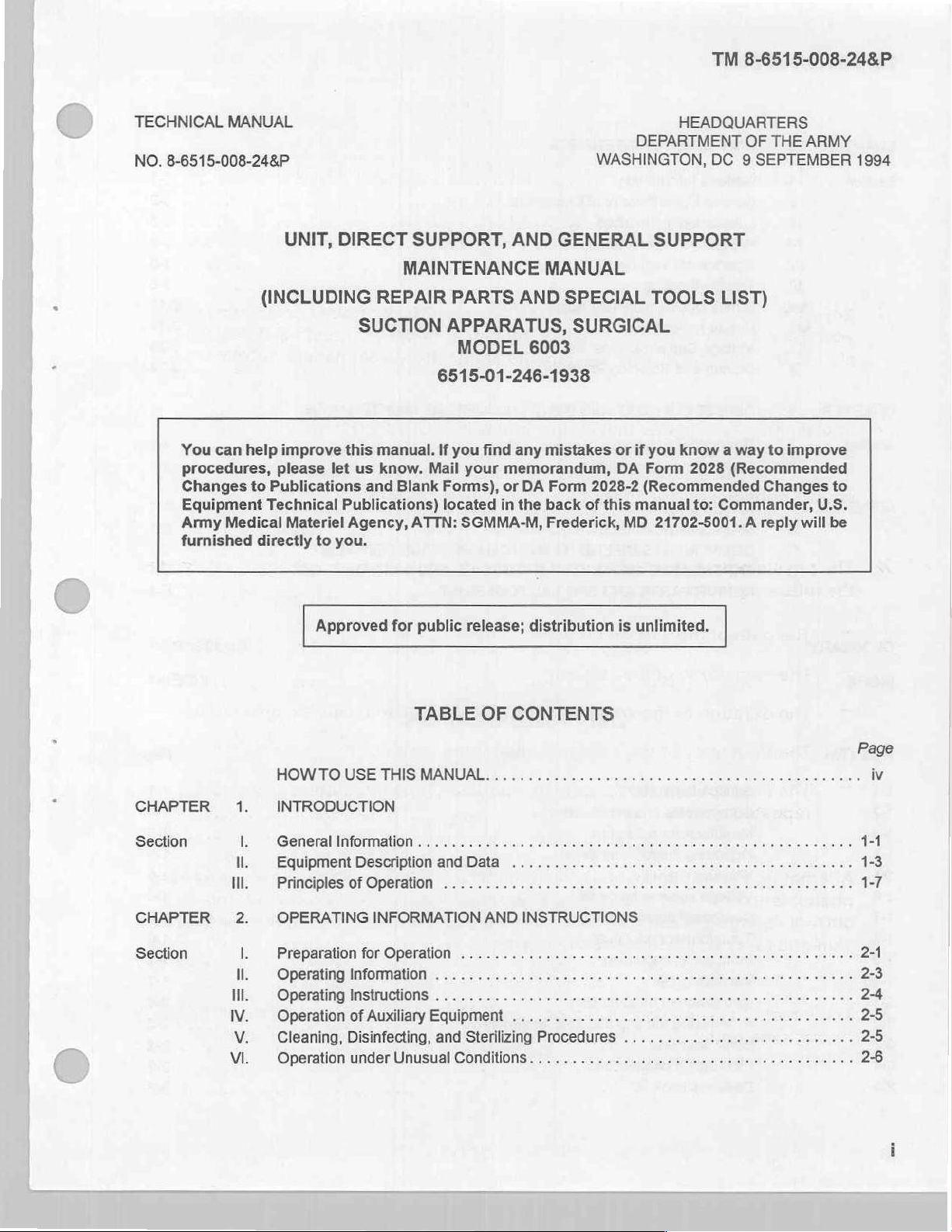
TM
8-6515-008-24&P
UNIT,
DIRECT
MAINTENANCE
(INCLUDING
SUCTION
TECHNICAL
SUPPORT,
REPAIR
SPECIAL
APPARATUS,
MODEL
MANUAL
AND
TOOLS
6003
GENERAL
MANUAL
PARTS
LIST)
SURGICAL
SUPPORT
AND
APPROVED
HEADOUARTERS,
v
FOR
6515-01-246-1938
PUBLIC
RELEASE;
DISTRIBUTION
DEPARTMENT
OF
IS
UNLIMITED
THE
9
SEPTEMBER
ARMY
1994
Page 2
SAFETY
STEPS
TO
FOLLOW
IF
SOMEONE
IS
THE
Do
not
If
possible,
If
you
person
other
Send
After
cannot
insulating
for
the
try to
turn
to
safety
help
injured
VICTIM
pull or
off
the
turn
as
off
using a dry
material.
soon
person
OF
grab
the
ELECTRICAL
the
electrical
electrical
as
possible.
is
individual.
power.
power,
wooden
free
pole
of
contact
SHOCK
pull,
or a dry
push,
with
rope,
the
source
or
or
lift
the
some
of
electrical
immediately
shock,
start
move
artificial
the
resuscitation.
person
a
short
distance
away
and
Page 3
TM
8-6515-008-24&P
Throughout
time
to
read
Procedures
this
manual
these.
which
They
must
are
are
be
observed
WARNINGS,
there
to
WARNING
to
CAUTIONS,
protect
avoid
you
and
personal
and
NOTES.
the
equipment.
injury,
and
even
Please
loss
of
take
life.
Procedures
which
must
Essential
be
equipment,
observed
information
to
long-term
or
avoid
that
damage
health
should
equipment,
to
hazards.
remembered.
be
destruction
of
Page 4
TM
8-6515-008-24&P
»
»
»
ELECTRICAL
Severe
with
alert
The
caused
assigned
should
The
the
injury
live
to
the
electrical
current
consider
physiological
following
or
death
electrical
dangers
to
live
circuits.
parameter
to
flow
electrical
all
effect
factors:
can
result
Medical
of
exposed
that
is
called
circuits,
voltages
current
of
AND
ELECTRONIC
HAZARDS
when
circuits,
injures
VOLTAGE.
of
30
any
Equipment
terminals,
and
kills
power
or
flowing
supplies, and
more
part
Voltage
to
through
of
your
Repairers
power
is
CURRENT;
ratings
be
hazardous.
the
body
transmission
human
comes
must
be
panels,
the
force
are
normally
body
especially
and
in
contact
the
like.
that
lines.
related
is
You
to
2
»
Alternating
phenomenon
current
skin
»
The
through
collapse,
The
path
of
The
magnitude
duration
The
frequency
The
susceptibility
The
repeated
voltage source,
and
effect
shocks.
current
of
away
the
from
current
of
body;
unconsciousness,
the
current
of
the
of
of
tends
“skin
internal
prolonged
a
through
the
current.
voltage
voltage
the
damage
of
concentrate
to
effect.”
more
the
becomes
shock
The
body
more
current
death.
or
the
body.
discharge
or
alternating
if
heart
your
to
near
higher
likely
organs.
the
the
severe
flow
current.
from
body’s
the
frequency
current
the
with
cause
can
that
the
tend
will
length
severe
causes
current
surface
the
of
to
time
of
from
or
in
that
burns,
flow.
near
flows
it
current
and
because
alternating
flow
internal
of
the
the
Page 5
TM
8-6515-008-24&P
TECHNICAL
NO.
8-6515-008-24&P
You
can
procedures,
Changes
Equipment
Army
furnished
MANUAL
(INCLUDING
help
please
to
Publications
Technical
Medical
directly
UNIT,
improve
let
Materiel
to
you.
DIRECT
SUPPORT,
MAINTENANCE
REPAIR
SUCTION
this
manual.
us
know.
and Blank
Publications)
Agency, ATTN:
Mail
AND
GENERAL
MANUAL
PARTS
APPARATUS,
MODEL
AND
6003
SPECIAL
SURGICAL
6515-01-246-1938
If
you
find
any
mistakes
your
memorandum,
Forms),
located
or
in
SGMMA-M,
DA
Form
the
back
Frederick,
DEPARTMENT
WASHINGTON,
SUPPORT
TOOLS
or
if
you
DA
Form
2028-2
of
(Recommended
this
manual
MD
21702-5001. A reply
HEADQUARTERS
OF
DC 9 SEPTEMBER
LIST)
know a way
2028
(Recommended
Changes
to:
Commander,
THE
to
improve
ARMY
U.S.
will
1994
to
be
CHAPTER
Section
CHAPTER
Section
Approved
HOW
TO
1.
INTRODUCTION
I.
General
Il.
Equipment
Ni.
Principles
2.
OPERATING
I. © Preparation
|.
Operating
Ni.
Operating
IV.
Vi.
V.
Operation
Cleaning,
Operation
for
public
TABLE
USE
THIS
MANUAL.
Information
Description
of
Operation
INFORMATION
for
Operation
Information
Instructions
of
Auxiliary
Disinfecting,
under
Unusual
release;
OF
and
Data
.......
AND
Equipment
and
Sterilizing
Conditions.
distribution
is
unlimited.
CONTENTS
.
INSTRUCTIONS
.
Procedures
......................,.............,
1-3
1-7
Page 6
TM
8-6515-008-24&P
CHAPTER
3.
UNIT
LEVEL
MAINTENANCE
Section
CHAPTER
Section
APPENDIX
È
Il
Ill.
IV.
V.
VI.
Vil.
Vill.
IX.
X.
4.
I
Il.
A.
B.
ο.
D.
E.
General
Service
Lubrication
Preventive
Operational
Information.
Upon
Receipt
Instructions . ....,....... s «
Maintenance
Testing).
TOUDIGSHOOTAG,
Circuit
Repalr
Voltage:
Storing
DIRECT
General
Maintenance
Descriptions
Procedures...
Convérsion.Instructions...
and
Shipping
SUPPORT
Information,
Procedures.
RERERENCES
MAINTENANCE
COMPONENTS
EXPENDABLE
REPAIR
PARTSANDSPECİALTOOLSLIST.....................
..................................................
of
Equipment
Checks
Ου
inc
ccs
so ie
and
Adjustments
Procedures
AND
GENERAL
.…
....
..
.….......,,
..
212.60 & emare a 18 e TE
ALLOCATION
OF
END
ITEM
AND
DURABLE
......................................
s 6 6 sur
and
Services
erman
....................................
..............................
sz
A
A
+3 2 à à smic à à à
Ὁώωσ
à
8 4 6 à à
16 É É
ο
pirate
ο
IEA
нежнее
.......................................
SUPPORT MAINTENANCE
mate
de
carbone
ο
address
ου
RR E EATER
CHART
AND
BASIC ISSUE
SUPPLIES
AND
ITEMS
MATERIALS
LIST
...............
LIST
8 3 8 à à 3-2
e 6 3-8
»
# € +
ο
πο.
à 5 nt
ο
ERE
PIRA
ω
ων
ων
ων εν
............
00002
o
3-11
3-14
3-23
3-24
3-1
3-2
3-2
3-6
4-1
4-1
A-1
B-1
C-1
D-1
E-1
GLOSSARY
INDEX
Figure
No.
1-1
1-2
1-3
1-4
1-5
1-6
1-7
1-8
1-9
1-10
2-1
2-2
2-3
2-4
2-5
és
SaD
ου
Suction
apparatus . .
Components
Manufacturer
Operating
NWaming
Voltage
Cardboard
instructions
impRnt....
conversion
instruction
μη
Front
panel
1110111109 . .
Ms
Installation
Assembling
ο
χα ο ο
PVC
06 베 0196
tubiný
1009
of
the
CONAGGHONS . .
5
ga
6 E 8 5
LIST
OF
р
ο
E E USA
ILLUSTRATIONS
ο
RS
νο
ο
ρα
Title
ο
and
accessories
data
plate................................................
décal
οκ
decal...............................................
tag
ται
οσα
bacteria
filter
cap and
μμ
...........................................
αμ
κ
ον ο ον
..............................................
ο
ο
.
ο
erro
ο
es 6 dus
αν
à
.............................................
float
assembly
à
à à à 5 à aan
«κκ
...................................
à
à à à à 8
ο
ο
LAGUNA
αν
ενα
à 3 à 2 à mac
ο
Ευ
ο
6
masraneie à à 5 ÿ à Ed
αυ.
3 6 4
RER
GERE
GLOSSARY-1
TO
INDEX-1
REDE
RE
04
Ae rn
Be TE
NÆSE
TE
52465
ο.
ESR
зачать
Page
1-1
1-3
1-5
1-5
16
1-6
1-6
1-6
1-7
1-7
2-1
2-2
2-2
2-2
2-3
Page 7
TM
8-6515-008-24&P
Figure
2-6
3-1
3-2
3-3
3-4
3-5
3-6
3-7
3-8
3-9
3-10
E-1
E-2
E-3
E-4
E-5
E-6
No.
Title
Controls
Wiring
Schematie.diagrami:.......L------
Schematicdiagiam
PE
Swen
Suction
Bacteria
Control
Vacuumipumpiz
ος
Suction
Control/pump
Collection
Vacuum
Valve
Li
and
diagram...
ornentatlona
and
filter
circuit
πρ
apparatus
bottle
pump
and
manifold
mi
ye o Day
indicators
...
ON
POB":
pressure
PCB.
module
valves
Essa
components . .
components
assembly
Components:
assembly
. >
«-rororre
oros
ar
dini
..
components.
320
components
e
LIST
OF
TABLES
0A
altar
one
lo
a
nan
uao
LARE
4152
................................
ei
o
de
ο ο ο
Al
el
mora
ta
ET
ET
eine
OI
eo
Ria
e
eye
een
EP
EE
.
55
es
ce
.
..
...
©
Page
2-3
3-11
3-11
3-12
3-13
3-15
3-17
3-18
3-19
3-20
3-22
.
Е-2
.
Е-6
.
E-8
E-10
E-12
E-14
Table
1-1
1-2
1-3
2-1
3-1
3-2
3-3
3-4
No.
Nomenclature
Miscellaneous
Зее
Peak
Operator
Repairer
Operator/user
Medical
preventive
preventive
troubleshooting................
Equipment
Title
cross-reference
characteristics . . z
maintenance
maintenance
Repairer
list
.
checks
checks
troubleshooting
and
and
services
services.
Sia
.......................
.......................
A
Page
1-2
.
14
1-4
2-5
3-3
3-5
.
3-8
.
3-9
Page 8

TM
8-6515-008-24&P
HOW
This
manual
capabilities,
scribes
must
beginning a maintenance
The
lowed
Use
general subject
subjects.
Multiple
manual.
names
equipment.
how
familiarize
manual
by
the
of
provides
functions,
to
set up,
is
arranged
appendixes, a glossary,
table
of
area
figures
Words
that
components
TO
all
and
operate,
yourself
contents
needed.
and
tables
are
or
USE
the
characteristics
with
task.
by
chapters,
to
help
The
are
both
words
THIS
information
test,
the
entire
an
locate
index
provided
capitalized
that
MANUAL
needed
of
and
repair
manual
sections,
index,
you
the
will
for
and
and
chapter
help
your
will
to
this
equipment.
the
before
and
DA
or
locate
ease
in
quotation
actually
understand
equipment.
operating
paragraphs
Forms
section
more
in
using
marks
see
2028-2.
for
specific
on
It
You
this
the
the
de-
or
fol-
the
are
Chapter 3 provides a systematic
the
equipment.
they
become a major
habit
and
Only
allocation
specified
training;
of
doing
anything
perform
for
test,
In
the
wrong
maintenance
chart
for
higher
measurement,
this
way,
problem
checks
will
your
levels
level
small
causing
and
services
be
detected
functions
of
maintenance
of
and
method
defects
maintenance.
diagnostic
of
can
the
equipment
in
the
quickly.
specified
frequently
inspecting
be
detected
same
Maintenance
equipment;
the
in
require
order
and
servicing
early
before
to
fail.
Make
each
maintenance
functions
additional
tools.
or
a
time
Page 9
TM
8-6515-008-24&P
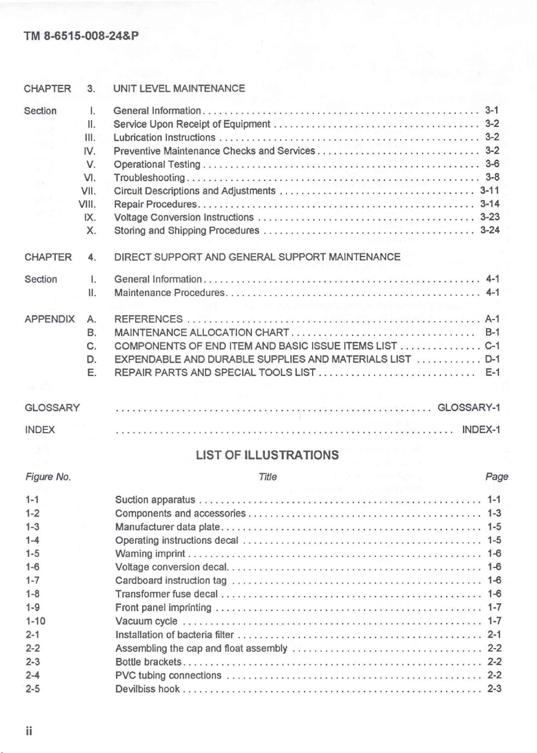
1-1.
This
erational
parts
decompression
Overview.
manual
and
a.
Type
and
special
b.
Model
c.
Purpose
describes
the
maintenance
of
manual.
tools
number
and
of
equipment.
or
suprapubic
Section
suction
functions,
Unit,
direct
list).
eguipment
drainage.
apparatus
services,
support
name.
To
provide
CHAPTER
INTRODUCTION
I.
GENERAL
(fig
1-1);
and
actions.
(DS),
and
Model
gentle
INFORMATION
provides
Additional
general
number
suction
6003,
for
1
eguipment
information
support
Suction
specialized
technical
(GS)
maintenance
Apparatus,
uses
data;
and
follows:
Surgical.
such
as
provides
(including
gastrointestinal
op-
repair
1-2.
Special
1-3.
TB
38-750-2
Explanation
or
unique
abbreviations,
Maintenance
prescribes
Figure
of
abbreviations
acronyms,
forms,
forms,
records,
records,
1-1.
and
and
reports,
Suction
terms
and
and
apparatus.
terms.
this
in
used
reports.
procedures.
manual
explained
are
in
the
glossary.
Page 10
TM
8-6515-008-24&P
1-4.
AR 40-61
series
1-5.
of
within
Destruction
contains
provides
Administrative
a.
Place
maintenance
the
time
maintenance
b.
Perform preventive
placing
PMCS
1-6.
Procedures
1-7.
TB
Army
to
ensure
c.
Inside
Preparation
Quality
740-10/DLAM
periodic
the
suction
effort
factors
records.
equipment
its
storage
to
prepare
of
instructions
information
apparatus
exists.
determined
in
operational
is
preferred
for
the
suction
control
4155.5/AFR
Army
materiel
for
destruction
and/or
storage.
in
administrative
This
equipment
by
maintenance
administrative
readiness.
for
equipment
storage
apparatus
(QC).
67-43
instructions
should
the
directing
checks
storage.
or
equipment.
for
contains
to
prevent
and
disposal
storage
be
authority.
and
services
When
selected
storing
QC
requirements
enemy
of
Army
on
the
destruction
for
only
in
mission
During
(PMCS)
equipment
for
administrative
or
shipping
medical
short
readiness
the
listed
is
are
listed
and
procedures.
use.
materiel.
of
medical
periods
condition
storage
in
removed
storage.
in
of
time
period,
tables
from
chapter
Also,
the
SB
materiel.
when a shortage
within
3-1
24
keep
appropriate
and
3-2
storage,
3,
section
hours
8-75
or
before
perform
X.
1-8.
Table
Nomenclature
1-1
identifies
1-9.
Reporting
Common
Cap
Overflow
Power
Pump
Stainless
Suction
Vacuum
Vacuum
improvement
AR
ment
40-61
prescribes
reports
for
official
name
and
float
protection
switch
cycle
indicator
steel
apparatus
select
setting
A
2800-mL
and
reports.
procedures
the
suction
cross-reference
versus
assembly
indicator
cover
switch
indicator
A
suction
commonly
Table
1-1.
device
apparatus
collection
bottle
processing
submitting
for
apparatus.
list.
used
nomenclatures.
Nomenclature
NOTE
is
also
is
commonly
medical
medical
cross-reference
Official
Cap
Float
Pilot
Cycle
Control/pump
Suction
Selector
White lamp
referred
to
known
materiel
materiel
list.
nomenclature
and
float
assembly
light
lamp
apparatus,
switch
as
an
aspirator.
as a 1-gallon
complaints
complaints
shut
off
module
surgical
and/or
mechanism
cover
bottle.
and/or
quality
>
quality
improve-
1-10.
A
warranty
1-2
Warranty
is
not
applicable.
information.
Page 11
Section
Il.
EQUIPMENT
DESCRIPTION
AND
DATA
1-11.
The
passages
120
incorporates
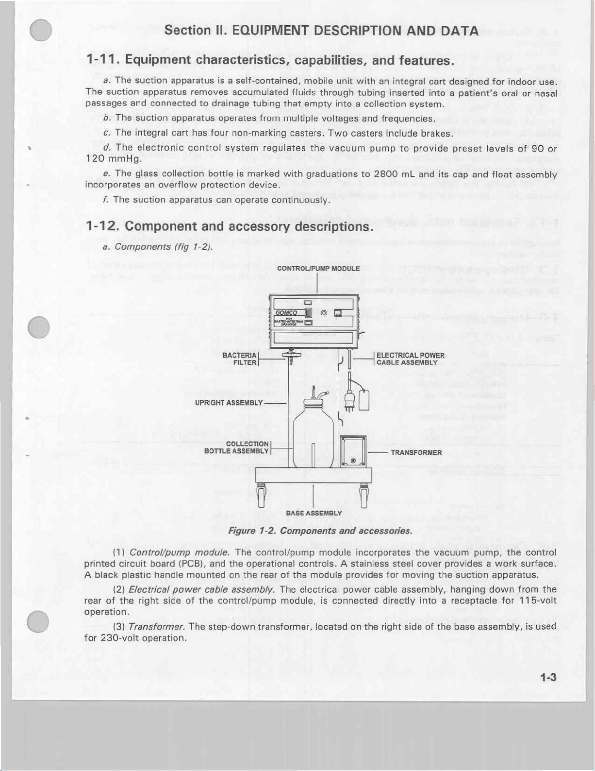
1-12.
Equipment
a.
The
suction
and
b.
The
c.
The
d.
The
mmHg.
e.
The
f.
The
suction
Component
a.
Components
suction
suction
integral
electronic
glass
apparatus
apparatus
connected
apparatus
cart
collection
an
overflow
apparatus
characteristics,
is a self-contained,
removes
control
(fig
to
has
protection
and
1-2).
accumulated
drainage
operates
four
non-marking
system
bottle
can
is
operate
accessory
tubing
marked
device.
capabilities,
fluids
that
from
multiple
casters.
regulates
with
continuously.
descriptions.
CONTROL/PUMP
mobile
empty
graduations
unit
through
into a collection
voltages
Two
the
vacuum
MODULE
and
with
tubing
and
casters
pump
to
2800
features.
an
integral
inserted
system.
frequencies.
include
to
provide
mL
brakes.
and
cart
into
its
designed
a
patient's
preset
cap and
for
indoor
oral
levels
float
use.
or
nasal
of
90
assembly
or
(1)
printed
A
rear
operation.
for
circuit
black
(2)
of
the
(3)
230-volt
plastic
Control/pump
board
handle
Electrical
right
Transformer.
operation.
power
side
UPRIGHT
module.
(PCB),
mounted
of
the
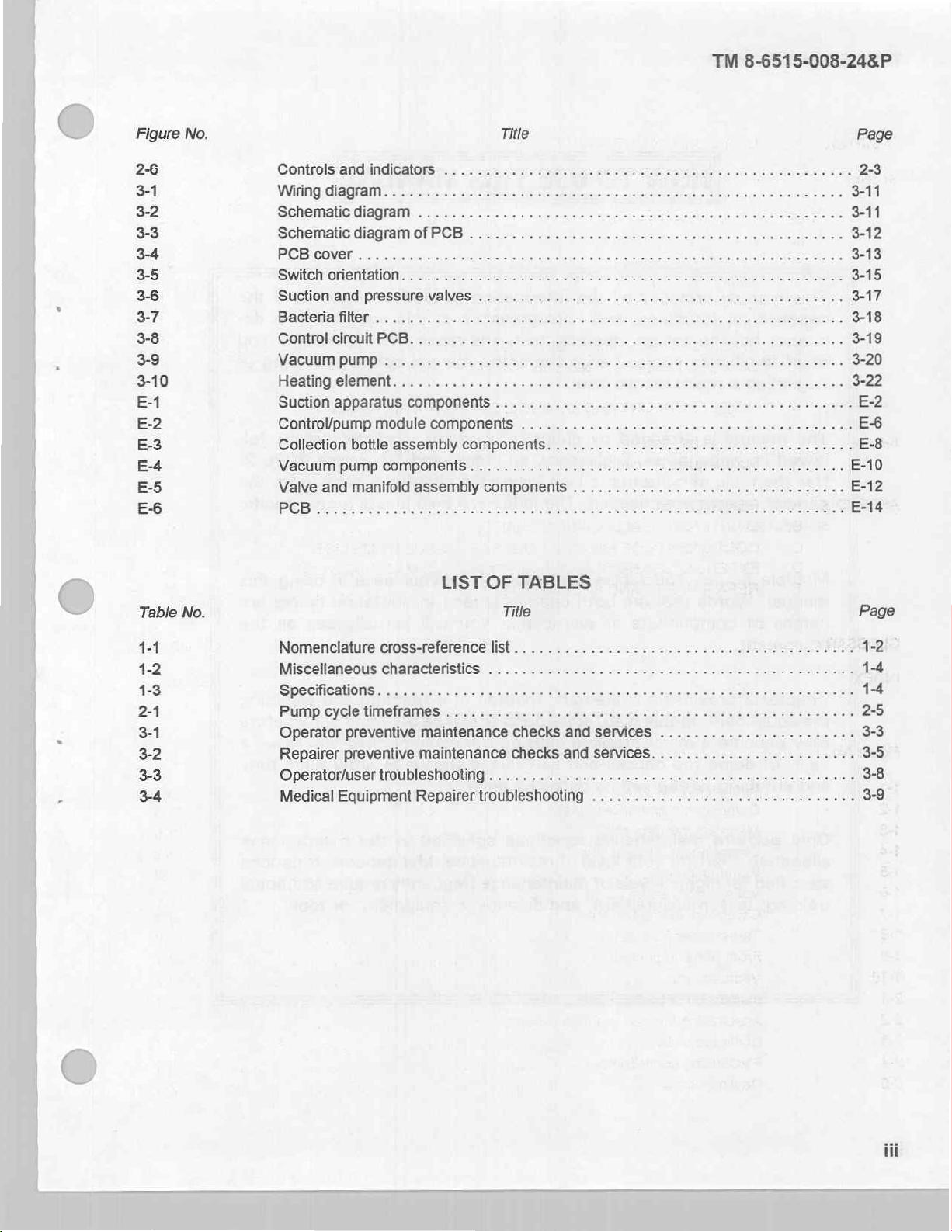
The
BACTERIA
FILTER
ASSEMBLY.
COLLECTION
BOTTLE
ASSEMBLY
Figure
The
and
the
on
cable
assembly.
control/pump
step-down
==
ΓΙ
1-2.
Components
control/pump
operational
the
rear
of
The
module,
transformer,
р
|
|
©
BASE
ASSEMBLY
and
accessories.
module
controls. A stainless
the
module
electrical
is
located
incorporates
provides
power
connected
on
ELECTRICAL
CABLE
—
TRANSFORMER
steel
for
cable
directly
the
right
POWER
ASSEMBLY
the
vacuum
cover
provides a work
moving
assembly,
side
the
hanging
into a receptacle
of
the
pump,
suction
base
assembly,
the
control
surface.
apparatus.
down
from
for
115-volt
is
the
used
1-3
Page 12
TM
8-6515-008-24&P
(4)
Base
operation.
(5)
Upright
for
the
control/pump
electrical
provide
bottle
apparatus.
while
chloride
power
for
storage
b.
Accessories.
(1)
Collection
cap,
and
(2)
Bacteria
The
blocking
(3)
Tubing.
(PVC).
assembly.
assembly.
module.
cable
assembly
of
the
bottle
an
overflow
filter.
filter
has a hydrophobic,
the
flow
of
The
disposable
Each
end
of
The
base
The
upright
The
of
suction
assembly.
protection
The
bacteria
aqueous
the
tubing
assembly
assembly
right
side
of
the
transformer.
apparatus
The
fluids.
tubing
electrical
collection
device.
filter
prevents
microporous
package
includes a graduated
incorporates
is
mounted
the
upright
Cable
bottle
contains a 15-inch
four
assembly
clips
power
assembly
fluid
membrane
size
casters
on
the
mounted
cable
and aerosol
which
connector.
and
base
provides
on
assembly.
consists
filters
and
the
transformer
assembly
cable
the
rear
of
of a 2800-mL
contamination
air
with
72-inch
length
and
provides
clips
the
upright
maximum
of
for
for
glass
of
the
clear
230-volt
support
storing
assembly
bottle,
suction
efficiency
polyvinyl
D
the
1-13.
The
suction
miscellaneous
operating/storing
Tabulated
tabulated
apparatus.
a.
Miscellaneous
Dimensions
A
data
characteristics
Height
Width
Depth;
Vacuum
Collection
Bacteria
Dütyeeyelei
Operating/storing
RMI
Temperature
Voltages/frequencies
Vacuum
90-mm
Flow
90-mm
Vacuum
ON
OFF
Vacuum
ON
OFF
data,
provides
characteristics
temperature
.
pump
resistance
bottle
filter
efficiency . . . .
ye
ranges
position
120-mm
rates
position
(air)
position
120-mm
position
pump
cycles,
TIME
TIME
pump
cycles,
TIME
TIME
decals,
miscellaneous
and
and
specifications
os
ranges,
ος
dimensions,
Table
ο
range
capacity
.
e
ula a ll
ranges
Sin
ey
yere
range
.......
..............
90-mm
position
120-mm
position
and
data
characteristics,
specifications.
to
include
and
weights.
1-2.
Miscellaneous
e
enti
세서
년
ee
va
in
a
yim
4.4.1444.
Table
1-3.
Specifications.
plates.
specifications,
Table
1-2
and
operating
characteristics.
83.2
cm
46.4
cm
42.5
cm
19.5
kg
155
to
2800
mL
.
0.3
micron
Continuous
90%
maximum
-17.78°C
115
VAC,
230
VAC,
85.5
to
114
to
0.25
Ipm
0.3
Ipm
2.1
to
19.0
to
3.4
to
19.0
to
and
table
voltages,
(32.75
(18.25
(16.75
(43
Ib)
160
ohms
(particles
(O°F)
to
50/60
or
50/60
Hz
99
mmHg
132
mmHg
2.25
sec
22.0
sec
3.75
sec
22.0
sec
other
1-3
provide a broad
vacuum
in)
in)
in)
in
air)
48.9°C
Hz
information
ranges,
(120°F)
for
range
flow
the
of
rates,
Page 13
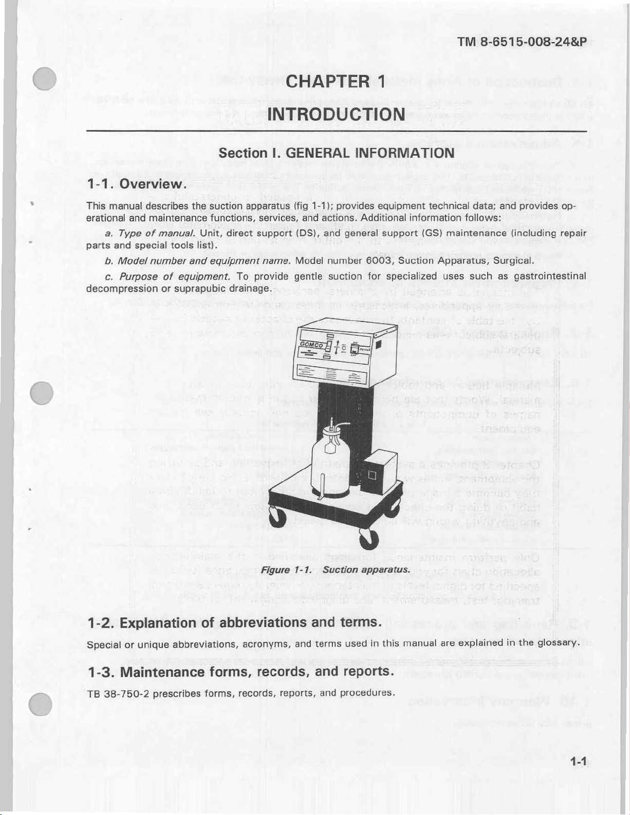
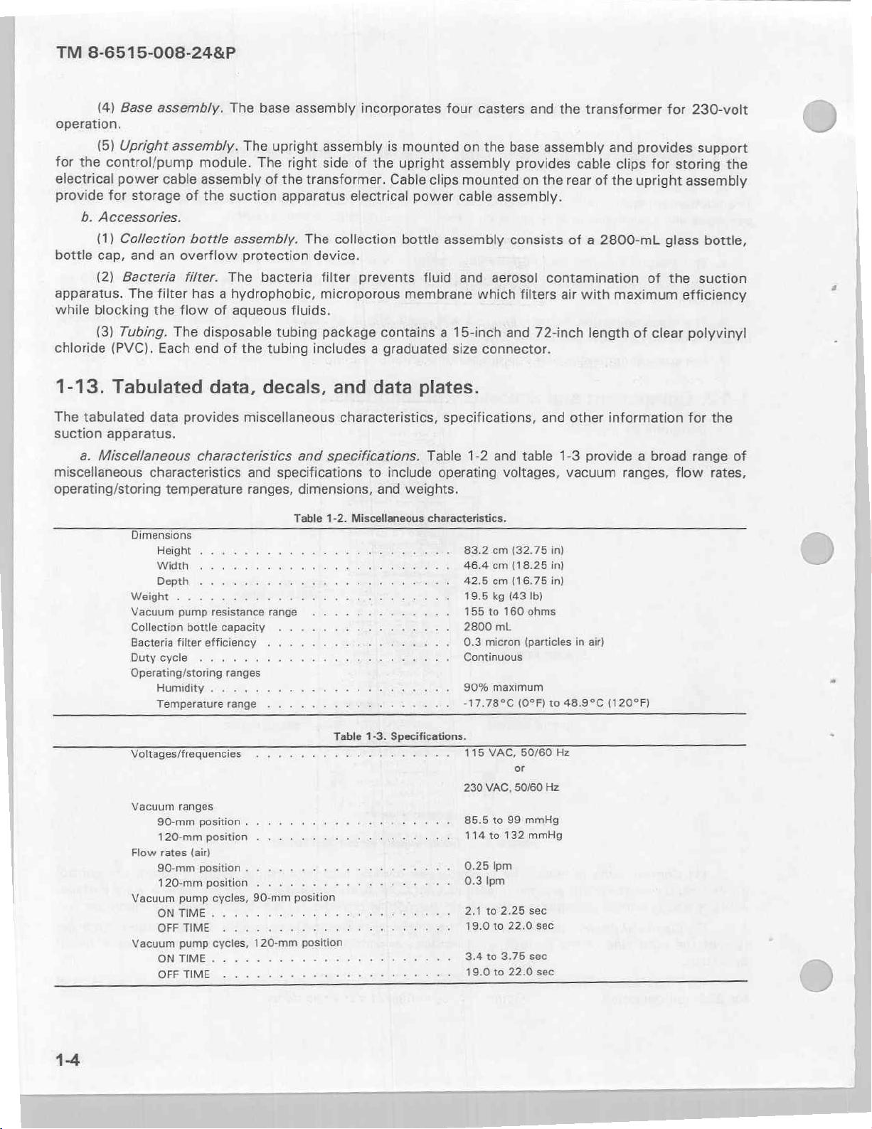
b.
module
Identification,
(1)
The suction
is
depicted
in
instruction,
apparatus
figure
1-3.
and
warning
manufacturer
Allied
plates,
MANUFACTURED
St
decals,
data
plate
GOMCO
Division
Healthcare
Products,
Louis,
MO
63110
BY
or
markings.
(located
Inc.
on
the
TM
right
8-6515-008-24&P
side
of
the
control/pump
is
depicted
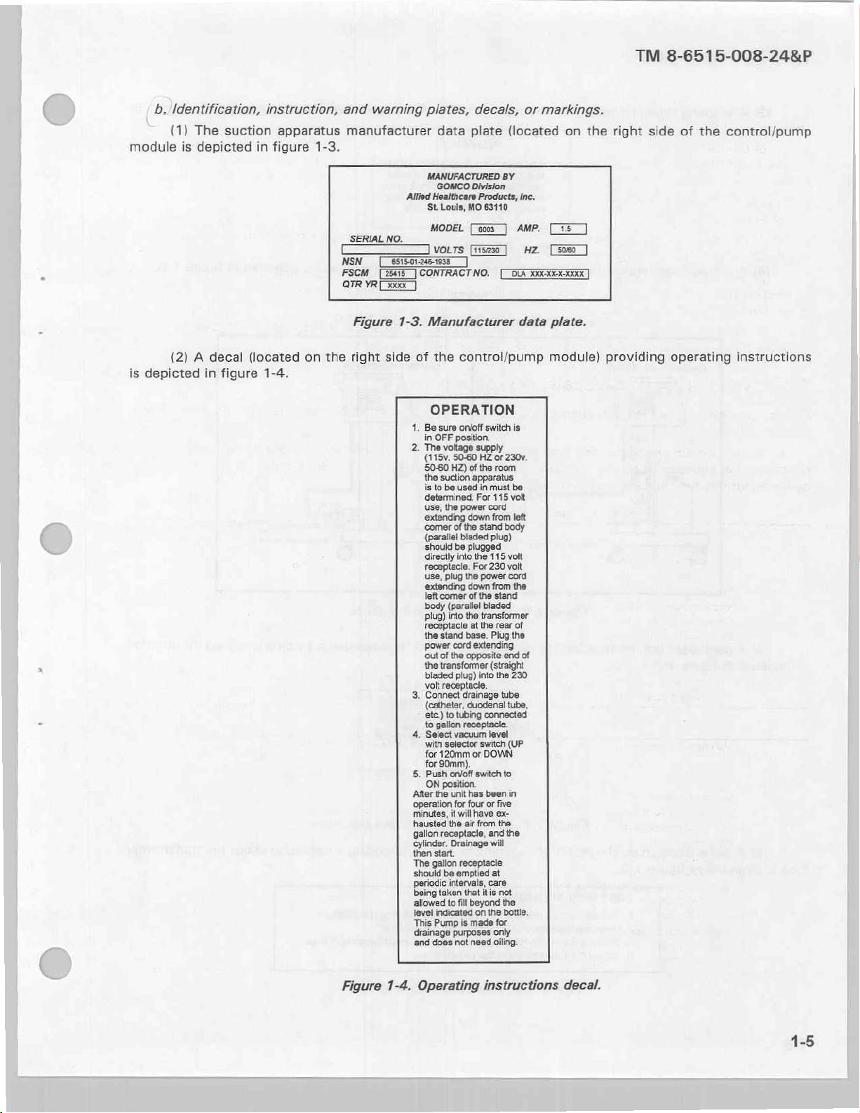
(2) A decal
in
figure
(located
1-4.
on
SERIAL
NSN
FSCM
QTRYR
Figure
the
right
NO.
[OE
]CONTRACT
DE]
1-3.
side
of
1.
2.
MODEL
VOLTS
[EEE]
NO.
Manufacturer
the
control/pump
OPERATION
Be
sure
onloff switch
in
OFF
position.
The
voltage
(115v.
50-60
the suction
is
determined.
use,
‘comer
(parallel
should
directly
plug)
receptacle
the
power
‘out
the
bladed
volt
Connect
“
supply
50-60
HZ
HZ)
to
be
the
into
stand
of
transformer
receptacle.
or
of
the
room
apparatus
used
in
must
For
115 volt
power
cord
ing
down
from
of
the
stand
bladed
plug)
be
plugged
into
the
115
the
transformer
at
the
base.
Plug
cord
extending
the
opposite
(straight
plug)
into
drainage
AMP,
НЕ
data
is
230v.
be
left
volt
rear
of
the
end
of
the
230
tube
TEE)
plate.
module)
providing
operating
instructions
Figure
i
with
selector
for
120mm
5.
Push
on/off
ON
position.
After
the
unit
‘operation
for
minutes,
it
hausted
gallon
cylinder.
then
The
should
periodic
being
allowed
level
This
drainage
and
1-4.
will
the
air
receptacle,
Drainage
start.
gallon
receptacle
be
emptied
intervals,
taken
that
to
fill
indicated
Pump
is
purposes
doss
not
Operating
i
switch
(UP
or
DOWN
switch
to
has
been
in
four
or
five
have
ex-
from
the
and
the
will
at
care
it
is
not
beyond
the
on
the
bottle.
made
for
only
need
oiling.
instructions
decal.
1-5
Page 14
TM
8-6515-008-24&P
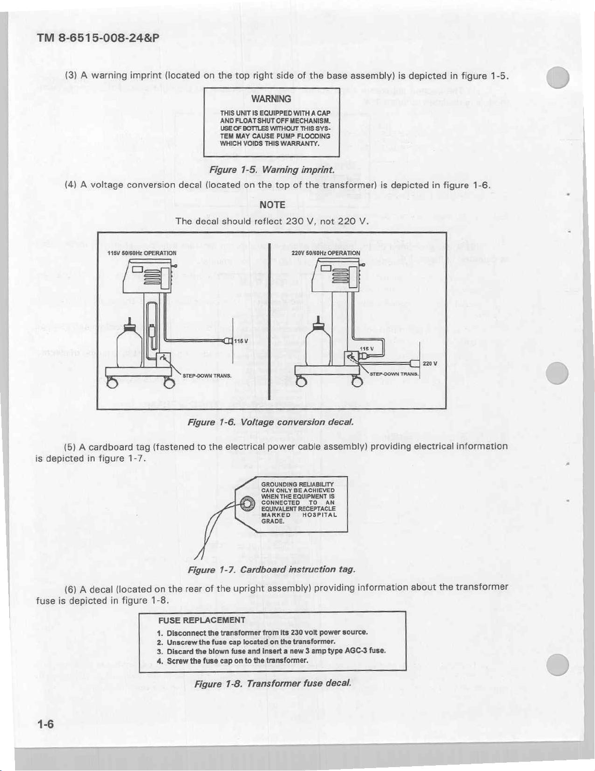
(3) A warning
(4) A voltage
115V
imprint
conversion
50/60Hz
OPERATION
=]
(located
decal
The
‘STEP-DOWN
on
Figure
(located
decal
TRANS,
the
top
WARNING
THIS
UNIT
AND FLOAT
USE
TEM
WHICH
should
IS
OF
BOTTLES
MAY
CAUSE
VOIDS
1-5.
on
fsv
right
side
EQUIPPED
SHUT
OFF
WITHOUT
PUMP
THIS
WARRANTY.
Warning
the
top
NOTE
reflect
of
the
base
WITH A CAP
MECHANISM.
THIS
SYS-
FLOODING
imprint.
of
the
transformer)
230
V,
not
220V
50/60Hz
OPERATION
220
assembly)
is
V.
sv
‘STEP-DOWN
is
depicted
depicted
TRANS.
in
in
figure
figure
1-5.
1-6.
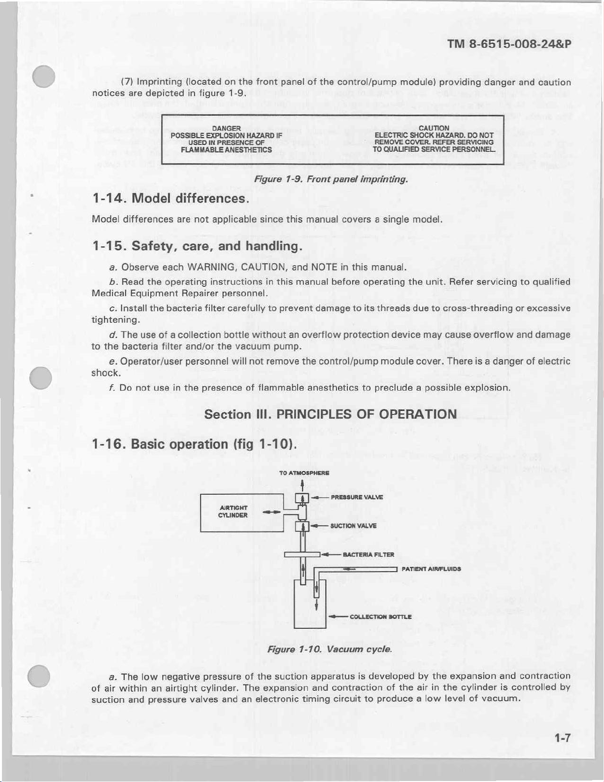
(5) A cardboard
is
depicted
(6)
fuse
is
depicted
tag
in
A
figure
decal
1-7.
(located
in
figure
Figure
(fastened
Figure
rear
the
on
1-8.
FUSE
REPLACEMENT
4.
Disconnect
2.
Unscrew
3.
Discard
4,
Screw
the
to
the
the
of
the
the
fuse
the
blown
fuse
Figure
1-6.
Voltage
electrical
1-7.
Cardboard
upright
transformer
cap located
fuse
and
cap
on
to
the
1-8.
Transformer
conversion
power
GROUNDING
CAN
WHEN
CONNECTED
EQUIVALENT
MARKED
GRADE.
assembly)
from
insert a new 3 amp
transformer.
ONLY
BE
THE
EQUIPMENT
instruction
its
230
on
the
transformer.
cable
RELIABILITY
ACHIEVED
TO
RECEPTACLE
HOSPITAL
providing
volt
fuse
decal.
assembly)
IS
AN
tag.
power
source.
type
AGC-3
decal.
providing
information
fuse.
electrical
the
about
information
transformer
Page 15
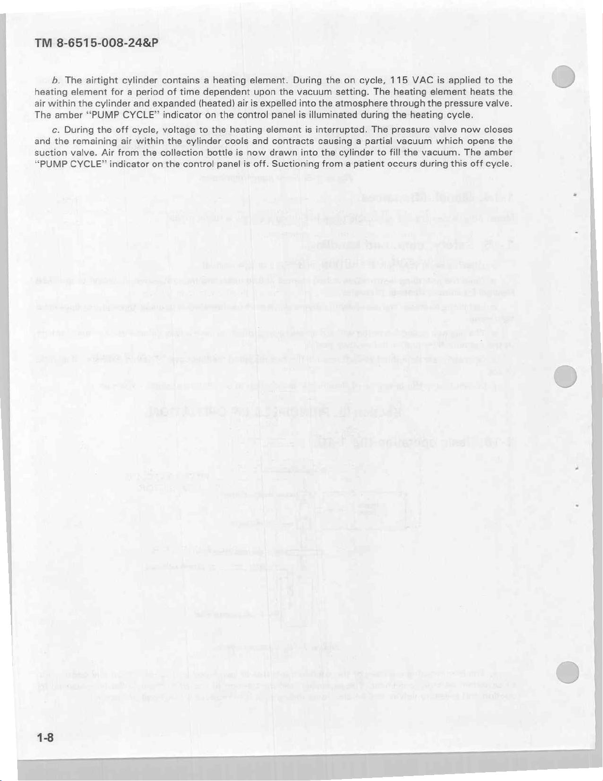
notices
(7)
Imprinting
are
depicted
POSSIBLE
(located
in
figure
DANGER
EXPLOSION
USED
IN
FLAMMABLE
PRESENCE
on
the
front
1-9.
HAZARD
ANESTHETICS
OF
Figure
panel
IF
7-9.
of
the
Front
control/pump
ELECTRIC
REMOVE
TO
panel
imprinting.
module)
‘CAUTION
SHOCK
COVER.
QUALIFIED
SERVICE
TM
providing
HAZARD.
REFER
SERVICING
PERSONNEL
8-6515-008-24&P
DO
danger
NOT
and
caution
/
<=
1-14.
Model
1-15.
Medical
tightening.
to
Model
differences
Safety,
a.
Observe
b.
Read
Equipment
c.
Install
d.
The
use
the
bacteria
e.
Operator/user
the
the
of a collection
shock.
f.
Do
not
use
1-16. Basic
differences.
are
not
applicable
care,
each
WARNING,
operating
Repairer
bacteria
filter
and/or
personnel
in
the
operation
and
instructions
personnel.
filter
carefully
bottle
the
presence
Section
since
handling.
CAUTION,
in
to
without
vacuum
will
not
remove
of
flammable
III.
(fig
1-10).
this
manual
and
NOTE
this
manual
prevent
an
pump.
overflow
the
before
damage
control/pump
anesthetics
PRINCIPLES
TO
ATMOSPHERE
covers a single
in
this
manual.
operating
to
its
threads
protection
to
OF
device
module
preclude a possible
OPERATION
model.
the
unit.
due
may
cover.
Refer
servicing
to
cross-threading
cause
overflow
There
is a danger
explosion.
to
qualified
or
excessive
and
damage
of
electric
ーー
PRESSURE
VALVE
PATIENT
AIRFLUIDS
Figure
|
a.
of
air
within
suction
The
and
low
negative pressure
an
airtight
pressure
valves
cylinder.
and
of
the
The
expansion
an
electronic
1-10.
suction
timing
Vacuum
apparatus
and
contraction
circuit
cycle.
is
developed
of
the
to
produce a low
by
air
the
in
the
level
expansion
cylinder
of
vacuum.
and
contraction
is
controlled
by
Page 16
TM
8-6515-008-24&P
b.
The
airtight
heating
air
The
and
suction
“PUMP
element
within
amber
c.
During
the
valve.
CYCLE”
the
cylinder
“PUMP
the
remaining
cylinder
for a period
and
CYCLE”
off
cycle,
air
within
Air
from
indicator
contains a heating
of
time
expanded
indicator
voltage
the
the
collection
on
the
(heated)
to
cylinder
control
dependent
air
on
the
control
the
heating
cools and
bottle
is
panel
element.
upon
is
expelled
element
now
is
off.
During
the
vacuum
into
panel
is
illuminated
is
contracts
drawn
into
Suctioning
the
on
cycle,
setting.
the
atmosphere
interrupted.
causing a partial
the
cylinder
from a patient
The
during
The
to
115
VAC
heating
through
the
heating
pressure
vacuum
fill
the
occurs
is
applied
element
the
pressure
cycle.
valve
which opens
vacuum.
during
this
heats
now
The
off
to
the
the
valve.
closes
the
amber
cycle.
Page 17
TM
8-6515-008-24&P
OPERATING
2-1.
This
nance
sufficient
trained
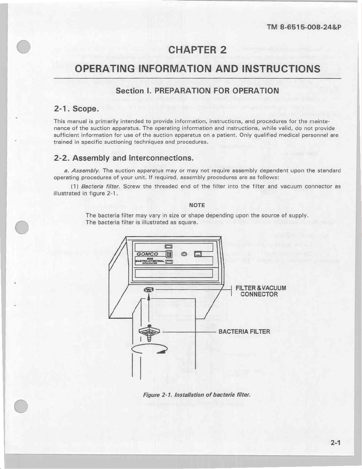
2-2.
operating
illustrated
Scope.
manual
of
the
information
in
specific
Assembly
a.
Assembly.
procedures
(1)
Bacteria
in
is
primarily
suction
figure
The
bacteria
The
bacteria
Section
intended
apparatus.
for
use
suctioning
and
The
suction
of
your
filter.
Screw
2-1.
filter
filter
CHAPTER
INFORMATION
I.
PREPARATION
to
provide
The
operating
of
the
suction
techniques
interconnections.
apparatus
unit.
If
required,
the
threaded
may
vary
is
illustrated
information,
apparatus
and
procedures.
may
in
size
as
square.
information
or
may
assembly
end
or
shape
on a patient.
not
of
the
NOTE
depending
2
AND
FOR
instructions,
and
require
procedures
filter
OPERATION
instructions,
assembly
into
upon
INSTRUCTIONS
and
Only
are
the
procedures
while
qualified
dependent
as
follows:
filter
the
source
and
for
valid,
medical
upon
vacuum
of
supply.
do
the
mainte-
not
provide
personnel
the
standard
connector
are
as
E
二
|
Figure
一
2-1.
Installation
一
|
of
bacteria
FILTER & VACUUM
CONNECTOR
BACTERIA
filter.
FILTER
2-1
Page 18
TM
8-6515-008-24&P
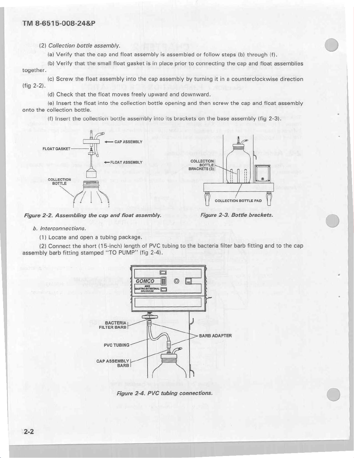
(2)
Collection
(a)
Verify
(b)
Verify
together.
(c)
Screw
(fig
2-2).
(d)
Check
(e)
Insert
onto
the
collection
(f)
Insert
FLOAT
GASKET-——
bottle
that
the
that
the
the
float
that
the
the
float
bottle.
the
collection
assembly.
cap
and
small
float
assembly
float
moves
into
the
bottle
+—
CAP
float
assembly
gasket
into
the
freely
collection
assembly
ASSEMBLY
is
in
cap
upward
bottle
into
is
assembled
place
prior
assembly
and
opening
its
brackets
or
to
connecting
by
turning
downward.
and then
on
follow
steps
the
cap and
it
in a counterclockwise
screw
the
base
the
assembly
(b)
cap
through
float
and
(fig
(f).
assemblies
float
assembly
2-3).
direction
Figure
b.
Interconnections.
(1)
(2)
assembly
COLLECTION
gi
FN
2-2.
Assembling
Locate
Connect
barb
fitting
the
and
open a tubing
the
short
stamped
«FLOAT
cap
and
package.
(15-inch)
“TO
PUMP”
BACTERIA
FILTER
BARB
PVC
TUBING
ASSEMBLY
float
length
assembly.
of
PVC
(fig
2-4).
tubing
to
the
COLLECTION
Figure
bacteria
2-3.
filter
Bottle
barb
BOTTLE
brackets.
fitting
PAD
and
to
the
cap
[>
BARB
ADAPTER
2-2
CAP
ASSEMBLY
BARB
Figure
2-4.
PVC
tubing
connections.
Page 19
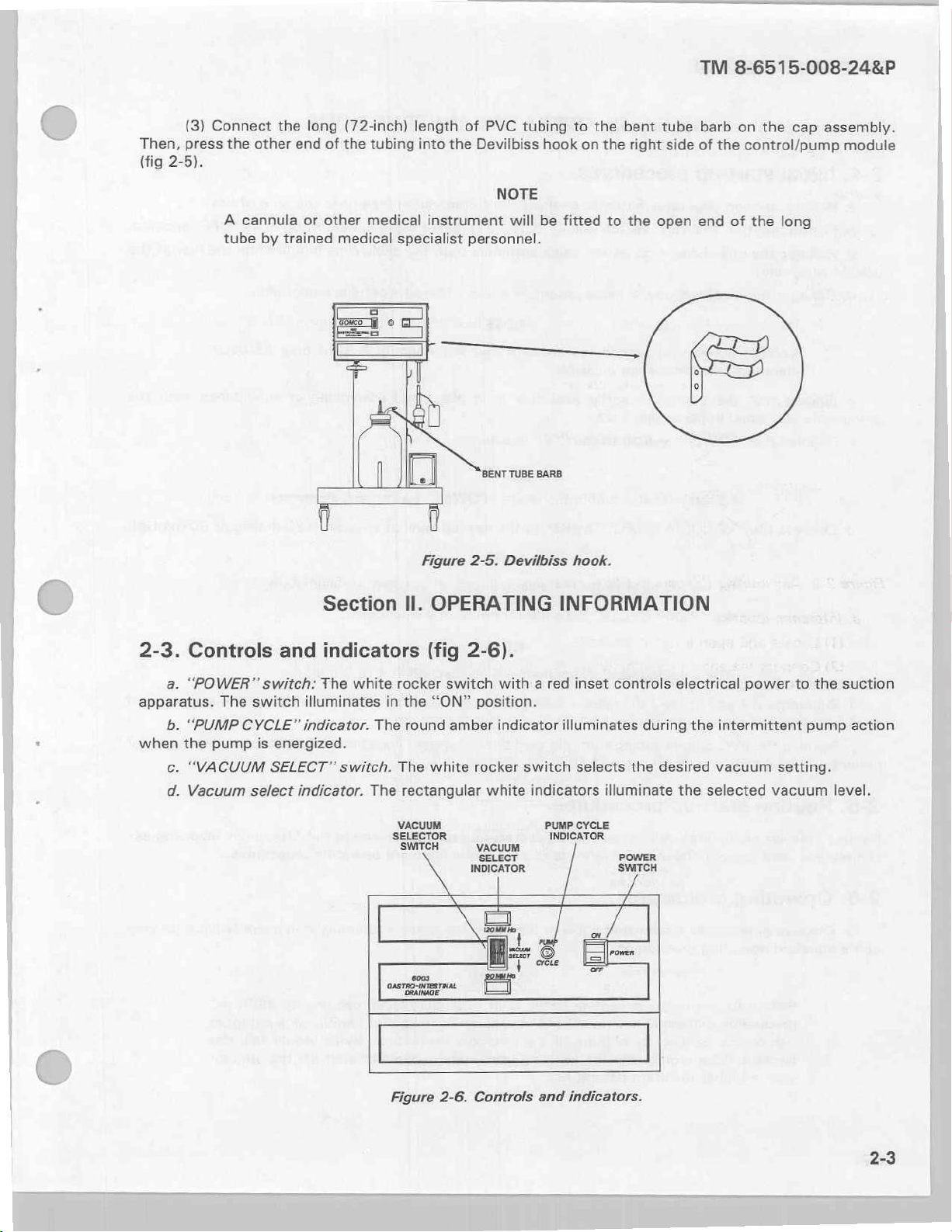
Then,
(fig
(3)
press
2-5).
Connect
the
A
cannula
tube
the
other
by
trained
long
(72-inch)
end
of
the
or
other
medical
medical
tubing
specialist
length
of
into
the
instrument
PVC
tubing
Devilbiss
NOTE
will
personnel.
hook
be
to
the
on
fitted
the
to
bent
right
the
tube
side
open
TM
8-6515-008-24&P
barb
on
the
cap
of
the
control/pump
end
of
the
long
assembly.
module
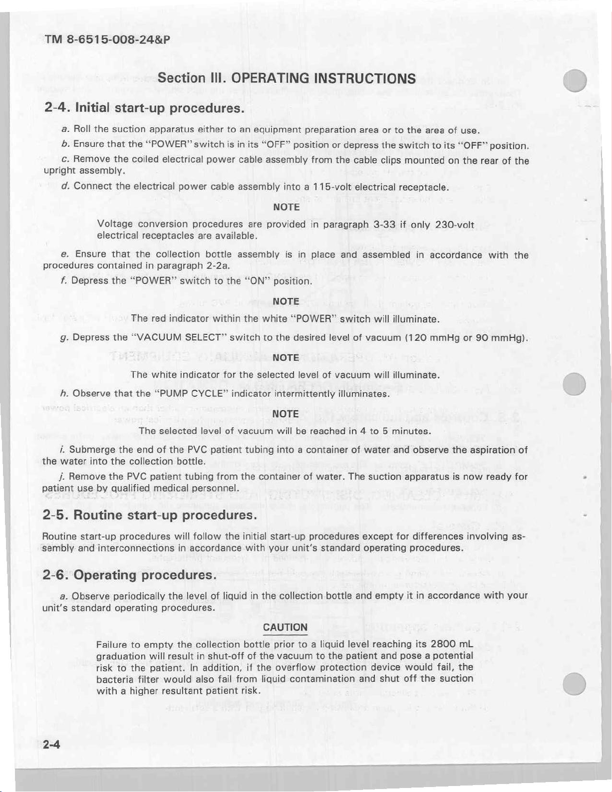
2-3.
apparatus.
when
Controls
a.
“POWER”
b.
“PUMP
the
c.
“VACUUM
d.
Vacuum
The
pump
and
switch:
switch
CYCLE”
is
energized.
SELECT”
select
Section
indicators
The
white
illuminates
indicator.
switch.
indicator.
|
Figure
Il.
OPERATING
(fig
2-6).
rocker
in
The
The
The rectangular
VACUUM.
SELECTOR
the
“ON”
round
white
SWITCH
switch
amber
BENT TUBE
2-5.
Devilbiss hook.
with a red
position.
indicator
rocker
VACUUM
INDICATOR
white
SELECT
switch
indicators illuminate
|
BARB
PUMP
INFORMATION
inset
controls
illuminates
selects
CYCLE
INDICATOR
I
during
the
POWER
SWITCH
electrical
the
desired
the
selected
power
intermittent
vacuum
to
setting.
vacuum
the
pump
level.
suction
action
από
Figure
2-6.
몰
ra
ΕΤ
Controls
and
indicators.
同一
=
Page 20
TM
8-6515-008-24&P
2-4.
upright
procedures
Initial
a.
Roll
b.
Ensure
c.
Remove
assembly.
d.
Connect
e.
Ensure
f.
Depress
g.
Depress
start-up
the
suction
that
the
the
the
Voltage
electrical
that
contained
the
“POWER”
The
the
The
Section
procedures.
apparatus
“POWER”
coiled
“VACUUM
electrical
electrical
conversion
receptacles
the
collection
in
paragraph
red
indicator
white
III.
either
switch
power
power
switch
indicator
cable
procedures
are
available.
bottle
2-2a.
to
within
SELECT”
OPERATING
to
an
equipment
is
in
its
“OFF”
cable
assembly
assembly
NOTE
are
provided
assembly
the
“ON”
position.
NOTE
the
white
switch
for
the
selected
to
the
NOTE
INSTRUCTIONS
preparation
position
into a 115-volt
is
in
“POWER”
desired
level
or
from
the
in
paragraph
place
level
of
vacuum
depress
and
switch
area
or to
the
cable
clips
electrical
3-33
assembled
will
of
vacuum
will
the
area
switch
receptacle.
if
to
mounted
only
in
accordance
its
230-volt
illuminate.
(120
mmHg
illuminate.
of
on
use.
“OFF”
the
or
90
position.
rear
of
with
mmHg).
the
the
р.
i.
Submerge
the
water
J.
Remove
patient
2-5.
Routine
sembly
2-6.
a.
unit's
Observe
use
into
by
that
the
the
the
qualified
Routine
start-up
and
procedures
interconnections
Operating
Observe
standard
periodically
operating
Failure
graduation
risk
to
bacteria
with a higher
the
“PUMP
The
selected
end
of
the
collection
PVC
patient
medical
start-up
will
procedures.
the
procedures.
to
empty
will
result
the
patient.
filter
would
resultant
CYCLE”
level
PVC
indicator
of
patient
bottle.
tubing
from
personnel.
procedures.
follow
in
accordance
level
the
In
the
of
liquid
collection
in
shut-off
addition,
also
fail
patient
vacuum
tubing
the
container
initial
with
in
the
bottle
of
the
if
the
from
risk.
intermittently
NOTE
will
be
reached
into a container
of
water.
start-up
your
CAUTION
prior
vacuum
overflow
liquid
procedures
unit's
collection
to a liquid
to
contamination
illuminates.
in 4 to 5 minutes.
of
water
The
suction
except
standard
bottle
the
protection
operating
and
level
patient
and
and
observe
apparatus
for
differences
procedures.
empty
reaching
device
it
and
pose a potential
would
shut
off
the
in
accordance
its
2800
fail,
the
suction
aspiration
is
now
involving
mL
the
ready
with
of
for
as-
your
2-4
Page 21
b.
Observe
c.
Observe
collection
contamination
d.
bottle
Observe
the
VACUUM
the
and
“PUMP
SELECT
90
mmHg
120
mmHg
flow
during
that
the
CYCLE”
LEVEL
of
patient
the
off
the
short
subsequent
indicator
period
15-inch
unplanned
Table
fluids
of
the
for
2-1.
within
“PUMP
length
shut-off
intermittent
Pump
cycle
timeframes.
INDICATOR
2.0
sec
3.5
sec
the
clear
CYCLE”
of
clear
of
the
illumination
ON
PVC
tubing.
indicator.
PVC
tubing
suction
to
as
indicated
Fluids
is
dry
the
patient.
TM
8-6515-008-24&P
in
table
INDICATOR
should
to
prevent
20
20
sec
sec
be
OFF
drawn
bacteria
2-1.
into
the
filter
2-7.
Shut-down
down
operating
2-8.
The suction
generator,
2-9.
Associated
Shut-down
a.
Depress
b.
Disconnect
the
suction.
ο.
Disconnect
d.
Dispose
procedures.
Associated
Associated
Section
procedures
the
the
the
of
both
Section
apparatus
which
is
material
V.
CLEANING,
procedures.
are
as
follows:
“POWER”
short
patient
lengths
switch
15-inch
from
of
IV.
support
requires
shared
with
material.
is
identified
to
the
“OFF”
length
the
tubing
long
and
of
clear
(72-inch)
collected
OPERATION
items
no
associated
multiple
in
appendix D and
of
equipment.
support
items
of
DISINFECTING,
position.
PVC
tubing
length
patient
OF
AUXILIARY
items
surgical
appendix
from
of
PVC
fluids
of
equipment
equipment
E.
AND
the
bacteria
tubing.
in
accordance
filter
with
EQUIPMENT
other
than
for
electrical
STERILIZING
barb
fitting
your
unit's
an
electrical
power.
PROCEDURES
to
shut
standard
power
2-10.
disinfecting,
designed
2-11.
General.
a.
The
b.
Accessories
and
ο.
The
Suction
a.
Cleaning.
(1)
Turn
Disconnect
(2)
(3)
Remove
Wipe
(4)
suction
collection
apparatus
and/or
sterilizing
identified
manufactured
bottle
apparatus.
off
the
suction
the
the
collection
suction
the
and
procedures
as
disposable
for
one
assembly
apparatus
electrical
bottle
apparatus
operating
are
use
only.
should
by
power
cable
assembly.
using
accessories
provided
should
be
depressing
a
removed
assembly
mild
not
detergent
should
in
subsequent
be
cleaned
from
the
“POWER”
from
with
the
the
be
base
a
clean
at
paragraphs.
and
reused.
assembly
switch
electrical
cloth.
soft
all
times.
These
to
facilitate
to
the
“OFF”
receptacle.
Specific
accessories
cleaning,
cleaning.
position.
were
2-5
Page 22
TM
8-6515-008-24&P
(5)
Dry
the
it
b.
Disinfecting.
with
disinfectant
suction
apparatus
Disinfect
in
accordance
the
with a soft
suction
with
apparatus
your
unit's
cloth.
by
standard
wiping
it
with a liquid
operating
disinfectant
procedures.
or
lightly
spraying
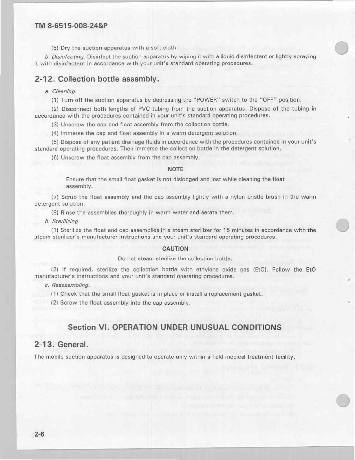
2-12.
accordance
standard
detergent
steam
Collection
a.
Cleaning.
(1)
(2)
(3)
(4)
(5)
(6)
(7)
(8)
b.
Sterilizing.
(1)
sterilizer’s
Turn
off
Disconnect
with
the
Unscrew
Immerse
Dispose
operating
Unscrew
Ensure
assembly.
Scrub
the
solution.
Rinse
the
Sterilize
bottle
the
suction
both
lengths
procedures
the
cap and
the
cap
and
of
any
patient
procedures.
the
float
that
the
small
float
assembly
assemblies
the
float
and
manufacturer
assembly.
apparatus
of
contained
float
float
assembly
drainage
Then
assembly
float
and
thoroughly
cap
assemblies
instructions
by
PVC
tubing
in
assembly
fluids
immerse
from
the
gasket
the
in
and
depressing
from
your
unit’s
from
the
in a warm
in
accordance
the
collection
cap
assembly.
NOTE
is
not
dislodged
cap
assembly
warm
water
in a steam
your
the
“POWER”
the
standard
collection
detergent
lightly
and aerate
sterilizer
unit’s
suction
operating
bottle.
with
the
bottle
and
lost
with a nylon
standard
switch
apparatus.
solution.
procedures
in
the
detergent
while
them.
for
15
minutes
operating
to
the
“OFF”
Dispose
procedures.
contained
solution.
cleaning
the
bristle
in
accordance
procedures.
of
float
brush
position.
the
tubing
in
your
in
the
with
in
unit's
warm
the
(2)
If
manufacturer's
c.
Reassembling.
(1)
Check
(2)
Screw
Section
2-13.
The
General.
mobile
suction
required,
instructions
that
the
the
float
apparatus
Do
sterilize
small
VI.
the
and
your
float
assembly
OPERATION
is
designed
not
steam
collection
unit's
gasket
into
the
to
CAUTION
sterilize
bottle
standard
is
in
place
cap
assembly.
UNDER
operate
the
collection
with
ethylene
operating
or
procedures.
install a replacement
UNUSUAL
only
within a field
bottle.
oxide
CONDITIONS
medical
gas
(EtO).
gasket.
treatment
Follow
facility.
the
Eto
2-6
Page 23
TM
8-6515-008-24&P
3-1.
unit
personnel
checking
operator
disassembly
tools.
Medical
fication/certification
modules,
class
information,
services
equipment,
the
personnel
the
Overview.
a.
Unit
level
on
its
assigned
(1)
Operator
and
for
accessories,
(2)
Specialist
Equipment
(a)
(b)
or
(c)
repair
(d)
(e)
(f)
in
accordance
(g)
Maintenance
b.
of
scope
will
vacuum
maintenance.
equipment.
maintenance.
consists
frayed
or
assembly
maintenance.
Repairers.
Scheduling
Performing
PCBs,
Operating a repair
parts
assemblies,
pump,
when
used
Maintaining a library
and
related
Conducting
Establishing
Notifying
functions.
operator/user
the
perform
PCB,
UNIT
Section
This
of
equipment
cables, and
and
replacing
of
the
The functions
and
performing
(CVC)
services.
unscheduled
available.
on
medical
materials.
inspections
administrative
with
TB
support
or
modules.
are
majority
the
stand.
or
CHAPTER
LEVEL
I.
GENERAL
level
of
maintenance
Responsibilities
This
segment
operational
stowing
operator
end
This
parts
equipment.
of
38-750-2.
maintenance
Maintenance
assigned
of
items
repair
item,
critical
segment
and
PMCS,
maintenance
program
technical
on
new
or
procedures
functions,
to
maintenance
MAINTENANCE
INFORMATION
is
the
are
stratified
of
unit
level
functions;
not
parts.
adjustments
of
services
electrical
to
include
manuals
transferred
battalions
level
unit
required
routine
in
use;
and
Replacing
unit level
include—
safety
functions
Class
(TMs),
equipment.
for
the
of
requirements
preventive
both
Maintenance
for
3
responsibility
as
follows:
maintenance
services
checking
operator
after
replacement,
maintenance
inspections
with
emphasis
VIII
repair
manufacturers’
control
the
and
and
Equipment
equipment
of
and
is
performed
like
cleaning,
for
loose
parts
will
or
is
performed
and
tests,
on
parts
as
well
literature,
administration
and/or
evacuating
corrective,
Repairer
except
performed
by
dusting,
hardware,
not
require
the
extensive
only
and
calibration/veri-
replacing
as
other
of
which
personnel.
tasks
some
by a using
operator/user
washing,
replacing
extensive
use
of
by
trained
assemblies,
commodity
repair
maintenance
unserviceable
beyond
are
These
involving
parts
3-2.
Common
pendix
(MTOE)
3-3.
Components
Tools
B,
for
Components
and
and
tools
section
authorized
end
of
test
III
test
equipment
this
of
items.
item
equipment.
required
manual.
item
end
of
issue
basic
and
Refer
for
your
to
and
items
maintenance
level
unit
modified
units
basic issue
appendix
in
listed
are
of
of
table
items.
C,
equipment
the
organization
sections
II
and
are
and
III
listed
equipment
manual.
this
of
in
ap-
3-1
Page 24

TM
8-6515-008-24&P
3-4.
Expendable
appendix
3-5.
Repair
3-6.
Special
this
3-7.
box
Expendable
Repair
parts
Special
tools
manual.
Unpacking
a.
Remove
b.
Open
c.
Lift
d.
Remove
e.
Lift
f.
Open
aside.
g.
Verify
(1)
(2)
(3)
(4)
(5)
(6)
(7)
and
durable
D,
section
parts.
reguired
tools.
required
Section
the
straps
the
top
upward
and
Suction
Maintenance
Operation
Collection
Bacteria
Tubing
Pressure
the
roll
the
small
receipt
on
foam
the
apparatus.
filters
(1
valve
supplies.
supplies
İl
of
this
for
unit
for
unit
Il.
the
suction
from
flaps
of
the
the
shipping
blocks
suction
cardboard
of
the
following
and
service
manuals
bottle
with
(3/pg).
15-inch
and 1 72-inch
and
and
materials
manual.
level
maintenance
level
maintenance
SERVICE
the
cardboard
container.
container
from
under
apparatus
carton
materiel:
manuals
(2).
cap
and
manifold
required
are
of
UPON
apparatus.
shipping
body
and
the
base
off
the
shipping
setting
float
assembly
on
(2).
assembies.
tubing
(spare).
lengths).
for
listed
in
the
equipment
RECEIPT
container.
remove
assembly.
container
the
base
maintenance
appendix
are
OF
it.
Set
it
Set
them
base.
assembly
of
the
equipment
E,
section
listed
Il
in
appendix
EQUIPMENT
aside.
aside.
Set
it
aside.
and
remove
of
this
the
are
listed
manual.
E,
section
contents.
Ill
Set
=>
in
of
the
3-8.
No
General.
lubrication
Section
3-9.
operation
serious
General.
The
a.
damage
of
suction
all
at
Section
the
suction
PREVENTIVE
IV.
apparatus
times.
or
Inspection
failure.
Ill.
apparatus
be
must
will
LUBRICATION
is
required.
MAINTENANCE
serviced
inspected
allow
and
defects
to
INSTRUCTIONS
CHECKS
systematically
discovered
be
and
AND
ensure
to
corrected
SERVICES
is
it
that
before
they
ready
result
for
in
Page 25
©
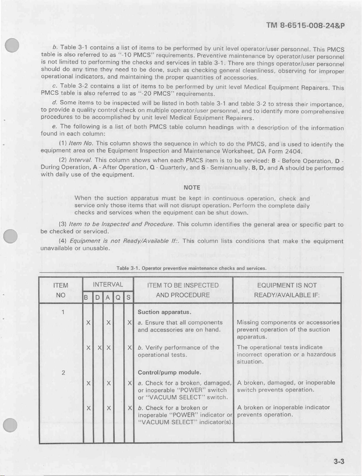
b.
Table
table
is
also
is
not
limited
should
operational
PMCS
to
procedures
found
equipment
During
With
do
c.
Table
table
d.
Some
provide
e.
The
in
(1)
(2)
Operation,
daily
each
/tem
Interval.
3-1
contains
referred
to
performing
any
time
indicators,
3-2
contains
is
also
items
to
a
quality
to
be
accomplished
following
column:
No.
This
area
on
This
A
use
of
the
When
service
checks
the
a
to
as
they
need
and
referred
be
inspected
control
is
a
list
column
the
Equipment
column
-
After
equipment.
suction
only
those
and
services
list
of
items
“-10
PMCS”
the
checks
to
be
maintaining
a
list
of
items
to
as
‘“-20
will
check
on
by
unit
of
both
shows
Inspection
shows
Operation,
apparatus
items
when
to
be
requirements.
and
services
done,
multiple
that
the
to
PMCS”
be
listed
level
PMCS
the
sequence
when
Q
-
Quarterly,
must
will
the
equipment
such
proper
be
performed
Preventive
in
table
as
checking
quantities
performed
requirements.
in
both
table
operator/user
Medical
table
and
each
not
Equipment
column
in
which
Maintenance
PMCS
and
S
NOTE
be
kept
disrupt
can
by
unit
level
3-1.
There
general
of
accessories.
by
unit
level
3-1
and
personnel,
Repairers.
headings
to
do
Worksheet,
item
is
to
-
Semiannually.
in
continuous
operation.
be
shut
operator/user
maintenance
are
things
cleanliness,
Medical
table
3-2
and
to
with
a
description
the
PMCS,
DA
be
serviced: B -
B,
operation,
Perform
down.
the
TM
by
operator/user
operator/user
Equipment
to
stress
identify
and
Form
D,
and
complete
8-6515-008-24&P
personnel.
observing
more
of
is
used
2404.
Before
A
should
check
This
personnel
personnel
for
improper
Repairers.
their
importance,
comprehensive
the
information
to
identify
Operation, D -
be
performed
and
daily
PMCS
This
the
(3)
be
checked
(4)
unavailable
ITEM
NO
1
2
/tem
to
or
serviced.
Equipment
or
unusable.
BlplAlols
x
XI
X
x
be
Inspected
is
not
INTERVAL
x
XI
X
X
X
and
Procedure.
Ready/Available
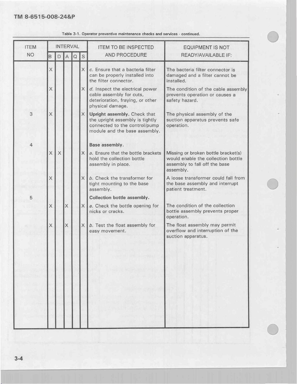
Table
3-1.
Operator
ITEM
Suction
X]
a.
Ensure
and
accessories
Xİ
6.
Verify
operational
Control/pump
a.
Check
or
inoperable
or
“VACUUM
b.
Check
inoperable
“VACUUM
This
If:.
preventive
TO
BE
AND
PROCEDURE
apparatus.
that
all
performance
tests.
module.
for a broken,
“POWER”
SELECT”
for a broken
“POWER”
SELECT”
column
This
column
maintenance
INSPECTED
components
are
on
of
damaged,| A broken,
or
indicator
indicator(s).
identifies
lists
checks
hand.
the
switch | switch
switch.
the
conditions
and
Missing
prevent
apparatus.
The
incorrect
situation.
A
or}
prevents
services.
broken
general
EQUIPMENT
READY/AVAILABLE
operational
area
that
components
operation
operation
damaged,
prevents
or
inoperable
operation.
make
tests
operation.
or
specific
the
equipment
IS
NOT
IF:
or
accessories
of
the
suction
indicate
or a hazardous
or
inoperable
indicator
part
to
Page 26
TM
8-6515-008-24&P
ITEM
NO
3
Table
INTERVAL
DIA
3-1.
la
Operator
preventive
ITEM
c.
Ensure
can
be
the
filter
d.
Inspect
cable
assembly
deterioration,
physical
Upright
the
upright
connected
module
maintenance
TO
BE
INSPECTED
AND
PROCEDURE
that a bacteria
properly
connector.
damage.
assembly.
and
installed
the
electrical
for
fraying,
assembly
to
the
the
base
checks
and
services - continued.
EQUIPMENT
READY/AVAILABLE
filter
into
power
cuts,
or
other
Check
control/pump | operation.
that
is
tightly
assembly.
The
bacteria
damaged
installed.
The
condition
prevents
safety
The
suction
hazard.
physical
apparatus
filter
connector
and a filter
of
the
operation
or
assembly
prevents
IS
NOT
cannot
cable
causes
of
IF:
is
be
assembly
a
the
safe
4
E
X
Base
assembly.
a.
Ensure
hold
the
assembly
b.
Check
tight
mounting
assembly.
Collection
a.
Check
nicks
or
cracks.
b.
Test
the
easy
movement.
that
the
collection
in
place.
the
transformer
to
bottle
assembly.
the
bottle
float
assembly
bottle
brackets | Missing
bottle
for
the
base
opening
for
for
or
broken
would
assembly
assembly.
A
the
patient
The condition
bottle
operation.
The
overflow
suction
loose
base
assembly
float
enable
to
transformer
assembly
treatment.
assembly
and
apparatus.
bottle
the
collection
fall
off
the
could
and
of
the
collection
prevents
may
interruption
bracket(s)
bottle
base
fall
from
interrupt
proper
permit
of
the
3-4
Page 27
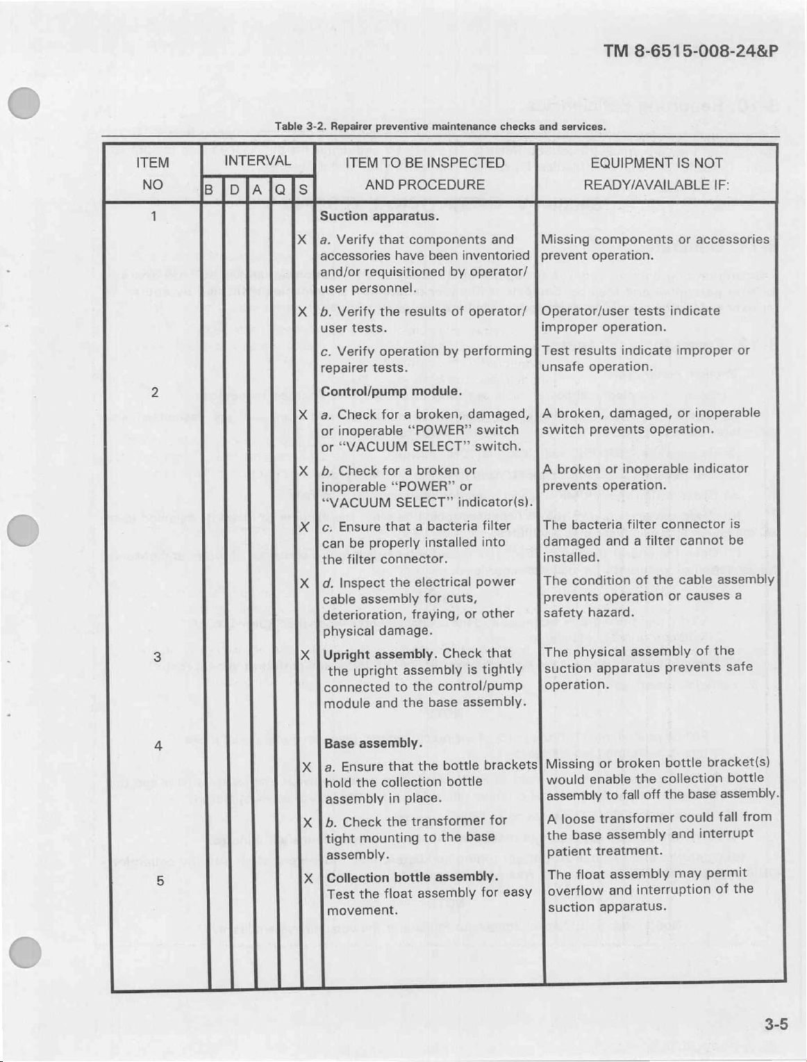
TM
8-6515-008-24&P
Table
3-2.
Repairer
ITEM
NO
1
INTERVAL
Suction
a.
accessories
and/or
user
b.
user
c.
repairer
preventive
ITEM
TO
AND
apparatus.
Verify
Verify
Verify
that
requisitioned
personnel.
the
tests.
operation
tests.
maintenance
BE
INSPECTED
PROCEDURE
components
have been
by
results
by
checks
and
services.
and
inventoried | prevent
operator/
of
operator/ | Operator/user
performing | Test
Missing
improper
results
unsafe
EQUIPMENT
READY/AVAILABLE
components
operation.
tests
operation.
indicate
operation.
IS
or
indicate
improper
NOT
IF:
accessories
or
2
3
4
5
Control/pump
a.
Check
or
inoperable
or
“VACUUM
Check
b.
inoperable
“VACUUM
Ensure
c.
can
the
d.
cable
deterioration,
physical
Upright
the
connected
module
Base
a.
hold
assembly
b.
tight
assembly.
Collection
Test
movement.
properly
be
filter
Inspect
assembly
assembly.
upright
and
assembly.
Ensure
the
Check
mounting
the
for a broken,
for
“POWER”
SELECT”
that
connector.
the
damage.
to
that
collection
in
the
bottle
float
module.
“POWER”
SELECT”
broken
a
bacteria
a
installed
electrical
cuts,
for
fraying,
Check
assembly
control/pump
the
base
the
bottle
the
bottle
place.
transformer
the
to
assembly.
assembly
damaged,
switch | switch
switch.
or
or
indicator(s).
filter
into
power
other
or
that
tightly
is
assembly.
brackets|
base
for
| A
A
prevents
The
damaged
installed.
The
prevents
safety
The
for
easy
broken,
prevents
broken
operation.
bacteria
condition
operation
hazard.
physical
loose
base
float
apparatus
or
enable
transformer
treatment.
apparatus.
[suction
operation.
Missing
would
assembly
A
the
patient
The
[overflow
suction
damaged,
operation.
inoperable
or
filter
filter
a
and
of
assembly
broken
the
off
fall
to
assembly
assembly
interruption
and
or
inoperable
indicator
connector
cannot
cable
the
causes
or
of
prevents
bottle
collection
base
the
could
interrupt
and
may
is
be
assembly
a
the
safe
bracket(s)
bottle
assembly.
from
fall
permit
the
of
Page 28
TM
8-6515-008-24&P
3-10.
Operator/user
PMCS”
forms.
3-11.
This
tor/user
tor/user
3-12.
interconnected
(90
the
Reporting
that
they
Consult
General.
section
personnel
personnel
Operator/user
a.
Vacuum
(1)
Connect
(2)
Verify
(3)
Depress
(4)
Depress
(5)
Observe
(6)
Close
mmHg)
aspiration
(7)
in
Open
deficiencies.
personnel
are
with
contains
will
unable
your
procedures
and
Medical
should
report
to
correct.
unit
Medical
Section
be
reported
problems
Refer
Equipment
V.
for
operational
Equipment
to
tests.
pump
approximately 4 to 5 minutes.
of
cycle.
the
that the
in
accordance
the
the
that the
the
open
the
end
water
electrical
components
with
“POWER”
“VACUUM
“PUMP
end
of
of
the
into
the
power
the
switch
SELECT”
CYCLE”
the
PVC
PVC
patient
collection
cable
and
procedures
to
with
the
suction
to
TB
38-750-2
Repairer
OPERATIONAL
testing
Repairer
Medical
assembly
accessories
the
“ON”
switch
indicator
patient
tubing
bottle.
personnel.
Equipment
into a 115-volt
contained
position.
to
the
intermittently
tubing
and
submerge
of
90
to
if
allow
apparatus
and
report
you
need
TESTING
of
the
Repairer
the
suction
in
paragraph
mmHg
illuminates.
the
it
discovered
the
deficiency
assistance.
suction
Deficiencies
level.
into a container
apparatus
personnel.
electrical
apparatus
2-2.
vacuum
to
identified
receptacle.
during
are
reach
of
their
using
by
assembled
its
water
“-10
the
proper
both
opera-
by
opera-
selected
and
observe
and
level
(8)
b.
Vacuum
(1)
collection
(2)
(3)
(4)
bottle
indicates
Verify
indicator
Remove
system
Follow
test
Pinch
bottle
Depress
Allow
the
Open
that
the
is
NOT
PVC
the
leak
procedures
is
performed
short
the
assembly.
the
“POWER”
suction
the
end
the
vacuum
Notify
your
water
illuminated.
patient
test.
(1)
independently.
length
forceps
Use
apparatus
PVC
the
of
system
unit
is
aspirated
tubing
through
(15-inch)
switch
to
patient
was
Medical
into
from
(6)
of
PVC
of
other
or
to
its
“OFF”
remain
tubing
properly
Equipment
NOTE
the
collection
container
the
NOTE
the
preceding
tubing,
similar
position.
undisturbed
and
sealed.
NOTE
Repairer
bottle
water
of
test
connected
instrument
approximately
for
if
Fast
the
listen.
when
and
(vacuum
between
hold
to
movement
vacuum
the
“PUMP
perform
pump
tubing
the
system
the
cycle)
bacteria
the
minutes.
5
air
of
leaks.
CYCLE”
next
if
this
closed.
the
into
test.
and
filter
collection
the
Page 29

TM
8-6515-008-24&P
3-13.
:
interconnected
open
that
that
if
either
the
interconnected
that
between
Verify
is
between
either
if
a.
end
the
the
PVC
b.
the
Vacuum
(1)
(2)
(3)
(4)
(5)
(6)
(7)
(8)
(9)
(10)
(11)
(12)
(13)
(14)
(15)
Pump
(1)
(2)
(3)
(4)
(5)
(6)
(7)
(8)
(9)
that
(10)
(11)
(12)
(13)
(14)
Medical
Connect
Verify
Connect
of
Depress
Depress
Observe
Allow
Observe
vacuum
Depress
Allow
Observe
vacuum
Perform
vacuum
Depress
Remove
patient
Shut
Connect
Verify
Close
Depress
Depress
Time
vacuum
19
Record
Depress
Time
the
19
Record
Perform
pump
Depress
Open
Shut
levels.
that
in
accordance
PVC
the
the
level
the
level
level
tubing.
down
cycles.
that
in
accordance
the
the
pump
and
22
the
the
vacuum
and
cycle
the
down
Equipment
the
electrical
the
a
mercury
patient
the
“POWER”
the
“VACUUM
that
the
vacuum
the
mercury
is
between
the
“VACUUM
vacuum
the
mercury
is
between
the
applicable
is
less
the
“POWER”
the
mercury
the
suction
the
electrical
the
end
of
the
the
“POWER”
the
“VACUUM
vacuum
seconds.
the
vacuum
22
the
the
the
pump
cycle
on
vacuum
“VACUUM
pump
seconds.
vacuum
applicable
either
is
“POWER”
patient
suction
the
Repairer
power
components
with
the
manometer,
tubing.
switch
SELECT”
“PUMP
components
pump
CYCLE”
pump
to
manometer,
85.5
SELECT”
pump
to
manometer,
114
troubleshooting
than
or
switch
manometer,
apparatus
power
with
the
patient
switch
SELECT”
cycles
between
is
cycle
pump
SELECT”
cycles
cycle
on
pump
troubleshooting
than
less
switch
tubing.
PVC
apparatus
cable
and
procedures
a
to
the
operate
the
mmHg
operate
mmHg
more
than
to
cable
and
procedures
PVC
tubing.
to
the
with
2.10
on/off
again
between
is
on/off
cycle
more
or
to
tests.
assembly
accessories
contained
calibrated
“ON”
switch
indicator
switch
the
the
switch
switch
to
for
approximately
calibrated
and
99
to
for
another
calibrated
and
132
procedures
the
specified
“OFF”
the
calibrated
by
following
assembly
accessories
contained
“ON”
to
stopwatch
a
and
period(s)
to
a
with
3.40
period(s)
procedures
than
“OFF”
the
following
by
into
a
115-volt
of
the
in
paragraph
vacuum
position.
the
intermittently
mmHg.
the
mmHg.
position.
into a 115-volt
position.
the
by
2.25
the
stopwatch
and
specified
the
position.
90
mmHg
vacuum
Record
120
mmHg
several
vacuum
in
levels.
vacuum
the
procedures
of
the
in
90
mmHg
observing
seconds
less
if
mmHg
120
seconds
3.75
less
if
in
procedures
the
gauge,
15
accordance
paragraph
than
by
accordance
electrical
suction
illuminates.
minutes.
gauge,
minutes.
gauge,
suction
and
observing
than
times
or
the
level.
or
the
vacuum
level.
or
gauge,
in
electrical
2-2.
level.
“PUMP
the
that
more
or
position.
and
more
or
in
contained
apparatus
2-2.
apparatus
seconds.
receptacle.
are
calibrator-analyzer
the
calibrator-analyzer.
level.
the
calibrator-analyzer.
with
this
chapter,
or
the
calibrator-analyzer
paragraph
receptacle.
vacuum
the
than
the
the
that
than
with
CYCLE”
the
“PUMP
vacuum
this
in
2-7.
are
pump
specified
CYCLE”
specified
the
chapter,
paragraph
assembled
into
section
assembled
indicator.
cycle
off
period.
indicator.
off
pump
section
2-7.
and
the
Verify
Verify
VI,
from
and
Verify
is
cycle
period.
VI,
Page 30

TM
8-6515-008-24&P
c.
Flow
rates.
(1)
Connect
(2)
Verify
interconnected
(3)
Open
Then,
insert
a
(4)
Depress
(5)
Depress
Allow
vacuum
(6)
Observe
percent.
flow
in
paragraph
(7)
(8)
(9)
rate.
(10)
(11)
Record
Depress
Allow
Observe
If
the
3-19.
Depress
the
electrical
that
the
components
in
accordance
the
short
calibrator-analyzer
the
“POWER”
the
“VACUUM
the
vacuum
pump
the
flowmeter
the
flow
the
“VACUUM
the
vacuum
the
calibrator-analyzer
flow
rates
Adjust
the
the
“POWER”
length
cylinder
rate.
pump
are
not
on
or
with
of
pump
off
power
cable
and
the
procedures
PVC
tubing
into
the
switch
within
to
SELECT”
to
operate
temperature.
and
verify
SELECT"
to
operate
and
the
cycles
to
switch
assembly
accessories
between
vacuum
the
“ON”
switch
for
the
switch
for
verify
specified
meet
the
to
the
“OFF”
into a 115-volt
of
contained
the
bacteria
system
to
and
position.
the
90
NOTE
approximately
vacuum
to
another
the
tolerances,
specified
flow
the
120
several
vacuum
position.
the
in
paragraph
reconnect
mmHg
15
rate
mmHg
minutes.
flow
refer
vacuum
electrical
suction
filter
and
level.
minutes
at
0.25
level.
rate
at
to
the
flow
apparatus
2-2.
the
the
system.
to
liters
0,30
control
rates
and
receptacle.
are
collection
create a stable
Ipm
+10
circuit
the
bottle
per
minute
percent.
adjustments
specified
assembled
assembly.
(Ipm)
Record
contained
on/off
and
+10
the
cycles.
3-14.
Repairer
operator/user personnel
not
3-15.
Operator/user
ble
SYMPTOM
1.
General.
a.
Troubleshooting
personnel
b.
This
manual
determined
Operator/user
troubleshooting
causes
“POWER”
and
POSSIBLE
INDICATOR
“POWER”
Electrical
Electrical
is
cannot
by
routine
corrective
CAUSE
CORRECTIVE
switch
Depress
power
Connect
power
Notify
Section
information
provided
will
be
list
diagnostic
troubleshooting.
procedures
actions.
MAINTENANCE
DOES
NOT
not
depressed
“POWER”
cable
assembly
the
electrical
cable
assembly
your
unit’s
for
suction
in
this
section.
indicated
all
possible
Table
ILLUMINATE.
to
switch.
not
power
is
Medical
VI.
TROUBLESHOOTING
apparatus
Corrective
by
the
phrase
malfunctions.
procedures,
are
provided
3-3.
Operator/user
“ON”
position.
connected
cable
assembly
defective.
Equipment
operator/user
actions
“Notify
notify
Repairer.
your
in
table
troubleshooting.
to a source
to
personnel
beyond
your
unit’s
Medical
If a malfunction
appropriate
3-3.
Each
symptom
of
electrical
the
correct
electrical
and
for
the
capability
Equipment
is
either
maintenance
is
power.
receptacle.
Medical
or
not
support
followed
Equipment
authority
Repairer.”
listed
by
or
unit.
possi-
of
is
Page 31

SYMPTOM
2.
“PUMP
3.
“VACUUM
4.
NO
POSSIBLE
CORRECTIVE
CYCLE”
“PUMP
CYCLE”
Notify
“PUMP
CYCLE”
Notify
SELECT”
“VACUUM
Notify
Control
circuit
Notify
SUCTION
Loosen
(VACUUM
or
Check
Defective
Replace
Unserviceable
Replace
Cap
assembly
Tighten
Defective
Notify
CAUSE
INDICATOR
your
your
INDICATOR
SELECT”
your
defective.
your
open
tubing
and
float
assembly.
float
bacteria
filter.
loose.
cap
suction
your
Table
MAINTENANCE
DOES
indicator
unit’s
indicator
unit’s
indicator(s)
unit’s
unit’s
PUMP
connection(s).
tighten
assembly.
filter.
assembly.
and/or
suction
unit’s
3-3.
Operator/user
NOT
defective
Medical
defective
Medical
NOT
ILLUMINATED.
defective.
Medical
Medical
Equipment
Equipment
WORKING).
tubing
connections.
valve.
Medical
Equipment
ILLUMINATE
(vacuum).
Equipment
(no
vacuum).
Equipment
troubleshooting
INTERMITTENTLY.
Repairer.
Repairer.
Repairer.
Repairer.
Repairer.
-
continued.
TM
8-6515-008-24&P
5.
LOW
3-16.
a.
Medical
followed
SYMPTOM
1.
“POWER”
SUCTION.
Loose
tubing
Tighten
Defective
Notify
Defective
Replace
Medical
Equipment
by
possible
POSSIBLE
CORRECTIVE
INDICATOR
Electrical
Repair
Defective
Notify
International
connections.
tubing
collection
your
bacteria
bacteria
Equipment
causes
CAUSE
power
cable
or
115-volt
your
connections.
bottle
unit’s
filter.
Repairer
and
Table
MAINTENANCE
DOES
NOT
assembly
replace
electrical
unit’s
Standards
assembly.
Medical
Equipment
filter.
Repairer
troubleshooting
corrective
3-4.
Medical
ILLUMINATE.
is
defective.
assembly.
receptacle.
power
distribution
Organization
Repairer.
troubleshooting.
procedures
actions.
Equipment
Repairer
personnel
(ISO)
shelter.
are
provided
troubleshooting.
or
correct
the
in
table
problem
3-4.
within
Each
the
symptom
is
3-9
Page 32

TM
8-6515-008-24&P
SYMPTOM
POSSIBLE
Defective
2.
“PUMP
3.
“VACUUM
CYCLE”
“PUMP
Defective
Defective
Defective
SELECT”
“VACUUM
Defective
Defective
CAUSE
CORRECTIVE
“POWER”
Replace
CYCLE”
Replace
Replace
Repair
Replace
Replace
Replace
Replace
switch.
INDICATOR
indicator
indicator.
PCB
control
PCB.
vacuum
vacuum
pressure
pressure
INDICATOR
SELECT”
indicator(s).
“VACUUM
switch.
PCB
control
PCB.
Table
3-4.
MAINTENANCE
switch.
DOES
defective.
circuit.
pump.
pump.
or
suction
or
indicator(s)
SELECT”
circuit.
Medical
NOT
valve(s).
suction
NOT
defective.
switch.
Equipment
Repairer
ILLUMINATE
valve(s).
ILLUMINATED.
troubleshooting - continued.
INTERMITTENTLY.
4.
5.
6.
NO
SUCTION
Defective
Unserviceable
Defective
Defective
NO
SUCTION
Defective
Unserviceable
LOW
SUCTION.
Defective
Defective
Defective
Defective
(VACUUM
float
Repair
or
bacteria
Replace
suction
Replace
PCB
control
Replace
(VACUUM
PCB
control
Replace
vacuum
Repair
collection
Repair
suction
Test
and
PCB
Replace
vacuum
Replace
PUMP
assembly.
replace
filter.
filter.
or
pressure
defective
circuit.
PCB.
PUMP
circuit.
PCB.
pump.
pump.
bottle
or
replace
or
pressure
replace
control
circuit.
PCB.
pump
heating
WORKING).
float
assembly.
valve(s).
valve(s).
NOT
WORKING).
assembly.
assembly.
valve(s).
valve(s).
heating
element.
element.
Page 33

6.
An
electrical
wiring
diagram
中
for
POWER
SWITCH
troubleshooting
90
mmHg
INDICATOR
is
provided
in
figure
TM
3-1.
8-6515-008-24&P
VACUUM
PUMP
3-17.
a.
3-3
to
b.
Section
General.
The
schematic
assist
you
PCB
control
VII.
diagram
in
understanding
circuit
adjustments
CIRCUIT
and
an
the
63
(02
VACUUM
see
4
は
120
mmHg
PUMP
INDICATOR
Figure
DESCRIPTIONS
illustration
operation
are
64
68
EN
NE
CYCLE
3-1.
also
INDICATOR
Wiring
of
the
of
the
provided
02
03
Ici | RI | R15
SELECT
PCB
control
NA
CONTROL
diagram.
control
in
this
SWITCH
R16
LOW
CIRCUIT|PCB)
AND
circuit
circuit.
section.
162
Mm
i
P P
u υ
T T
Load
4
©
|
ADJUSTMENTS
are
provided
7
in
figures
3-2
and
R2
Qi
C6
R1
D1
e
Z1
Lue
ーー
이
=
!
ДЫНИ
cz
Figure
3-2.
Schematic
diagram.
R13
3-11
Page 34

TM
8-6515-008-24&P
ει
LO
da
=
va
NW)
sa
me
[
]
da
sf
ーー
ζ9ι
I
NI
-
T
90
N
1
1nolzr
0,
CL
=
NI
e|
col
м]
и
531
lua
Де
|
n
=
vol
ole
L
te
:
leo
I
e
Sora
col
È
>
~
に
AG
5
L
て
са
gu
PL
d
E
gi
Sa
Lasa
col
Ht
PM
id
Sa
E
=L9
|
64
LL
La
ba
O
>
WWW
一
"oneweyas
au}
UO
Jeadde
iou
op
pue
sJolslsaJ
UUVO-Q
SIL
/
LH
PUE
‘9LH
‘GLH
:2J0N
3-12
JE
示
99
全
!Z
En
Figure
HE
29
3-3.
Schematic
Sera
<
diagram
of
OLA
Ov
SL
)
PCB.
Page 35

TM
8-6515-008-24&P
3-18.
a.
The
seconds
2.25
second
first
when
b.
The
C8)
and
zener
supplied
filters.
c.
Circuit
whose
determined
timing
circuit
a
“on
common
time”
timing
components
d.
Potentiometer
is
e.
Components
high
signal
7.
P2
time”
periods
Control
PCB
and a selectable
“on
electrical
power
through
by
activated
on
and
period.
during
circuit.
control
time”
power
supply
diode
(Z1)
D1
and
timing
RE,
have
is
components
IC2, a quad
which
(P3),
by a high signal
P2,
pin
12,
paralleled
Since
testing.
been
circuit
can
accomplished
R6,
“on
time”
be
selected
is
applied
of
the
to
develop
R1.
Z1
are
bilateral
are
R7,
R12,
IC2.
by
“on
time”
This
prevents
adjusted
R14
is
an
on/off
of
control
the
is
the
connected
switch.
used.
R11,
and
on
and
P1
and
is
and/or
is
normally
recycling
either
3.40
by
shorting
to
the
input/output
circuit
voltage
by
pin
C3
R5,
relatively
the
consists
required
an
integrated
between
The
C2
comprise
6,
IC2.
comprise
are
timer
verified.
removed
timer
which
to
3.75
seconds
terminals 4 and 5 together.
terminals.
of
diode
+9
VDC.
C6
regulating zener
circuit
IC1
pins
section
the
activated
short,
(IC1)
of
the
timing
longer
by a high
R14
(O
from
provides a fixed
(D1),
is
the
filter
diode.
(IC1).
1,
2,
this
switch
circuit
“on
time”
signal
ohms)
going
into
NOTE
from
the
control
or
2.10
resistor
capacitor
C7
and
This
IC
and
3.
that
during
period.
on
is
connected
the
“off
circuitry.
“off
to
2.25
seconds.
The
“on
(R1),
capacitors
for
the
C8
are
high
has
an
integral
The
pin 3 connection
is
turned
the
“off
This
circuit
pin
13,
IC2
between
time”
period
time”
time”
on
to
of
19
The
period
(C6,
1/2-wave
frequency
oscillator
determines
time”
period.
is
activated
obtain a shorter
pin
5,
until
both
to
22
2.10
to
occurs
C7,
and
voltage
noise
chip
used
the
This
by
IC2
and
“on
is
g.
The
rectifier
is
high,
to
one-half
the
for
3-19.
receptacle.
stainless
(fig
upward.
volt
and
paragraph
(SCR)
low,
Q2
Q2
is
h.
The
divide
the
of
oscillator
the
longer “on
Control
Ensure
a.
Ensure
b.
Remove
c.
d.
Remove
Remove
e.
3-4)
Set
Connect
f.
electrical
Verify
g.
assembled
output
Q1.
is
off
on
IC1
is
oscillator
that
frequency
that
steel
grasping
by
it
receptacle.
that
2-2.
of
the
The
and
gate
which
shorts
controlled
number
time”
circuit
the
the
that
six
the
cover.
aside.
the
cover.
fish
the
electrical
the
the
accordance
in
Set
timer
gate
drive
current
the
to
either a high
frequency
counts,
of
measured
period,
adjustments.
“POWER”
electrical
Phillips
them
Set
cover
paper
lightly
it
power
components
(IC1)
to
gate
by
and
switch
screws
aside.
it
aside.
with
with
is
connected
the
is
to
current
1,024
number
the
pin
at
227.56
power
from
cable
and
the
SCR
is
controlled
Q1
through
of
or
low
this
for
512
IC1
1,
Hz
“OFF”
its
in
is
cable
the
from
control
the
fingers
your
assembly
accessories
procedures
through a full
by
R2.
This
Q1
to
common.
state
by
input
used
be
short
position
of
circuit
pulling
and
a
into
in
are
Since
to
24.98
is
PCB
115-
place
circuit.
is
should
for
the
assembly
sides
contained
wave
bridge
R2,
Q2,
R4,
is
the
“on
This
is
on
pins
Q
the
calculate
for
Hz
“on
time”
depress
or
disconnected
the
(En
in
and
time”
the
12
and
output
oscillator
the
the
period.
the
FISH
PAPER
(Es)
|
MOUNTING
Figure
(BR1)
pin
period.
“off
13.
of
“off
switch
from
|
Г]
and a silicon
8,
IC1.
When
When
time”
The
will
IC1
frequency.
time”
to
the
COVER
|
|
SPACERS
3-4.
PCB
period.
IC1
change
period,
“OFF”
its
115-volt
|
cover.
controlled
pin
pin
8,
is
programmed
Therefore,
143.22
position.
electrical
—
Г]
8,
IC1
IC1
state
PCB
is
in
Hz
3-13
Page 36

TM
8-6515-008-24&P
h.
Depress
An
the
i.
Depress
indicator
verify
depressing
and
(2.65
j.
Observe
k.
Time
that
I.
If
the
common.
seconds)
illuminates.
the
the
on
the
The
both
the
“POWER”
electrical
suction
The
the
“VACUUM
that
the
vacuum
vacuum
cycle
is
“POWER”
Depress
by
turning
O-ohm
on
cycles
switch
shock
apparatus
red
indicator
“PUMP
pump
pump
on
not
within
switch
the
“POWER”
P1
clockwise
resistor
are
to
hazard
operating.
within
SELECT”
CYCLE”
on
cycle
cycle
the
to
the
switch
prevents
validated
the
“ON”
position.
WARNING
is
present
with
NOTE
the
white
switch
indicator
with a stopwatch
is
between
specified
“OFF”
to
the
or
for
intermittently
2.10
range,
position
to
the
increase
NOTE
control
adjusted.
the
“ON”
time
circuit
the
stainless
“POWER?”
90
mmHg
by
observing
and
2.25
momentarily
and
connect a O-ohm
position.
and
counterclockwise
from
steel
switch
illuminates.
switching
will
level.
the
seconds.
shut
Adjust
Verify
to
cover
removed
illuminate.
that
“PUMP
off
the
resistor
P1
to
approximately
to
the
off
the
applicable
CYCLE”
suction
between
decrease
cycle
until
and
indicator
apparatus
pin
mid-point
time.
white
and
5,
IC2
by
m.
Depress
indicator
n.
Time
and
verify
o.
lf
by
turning
p.
Again
suction
g.
Time
seconds.
r.
If
by
turning
s.
Depress
t.
Reinstall
the
PCB.
u.
Reinstall
v.
Reinstall
3-20.
the
illuminates.
the
vacuum
that
the
the
on
cycle
P2
clockwise
depress
apparatus
the
vacuum
the
off
cycle
P3
clockwise
the
the
the
the
General.
“VACUUM
pump
vacuum
is
not
to
the
“POWER”
on
by
depressing
pump
is
not
to
“POWER”
fish
paper
stainless
six
Phillips
SELECT”
on
cycle
pump
on
within
the
increase
off
cycle
within
increase
switch
PCB
steel
screws
19
cover
cover.
Section
switch
again
cycle
specified
time
and
switch
the
“POWER”
and
to
22
time
and
to
the
by
into
VIII.
for
the
with a stopwatch
is
between
range,
counterclockwise
to
the
verify
seconds,
counterclockwise
“OFF”
inserting
the
sides
3.40
adjust
“OFF”
switch
that
the
adjust
position.
its
of
REPAIR
120
mmHg
by
observing
and
3.75
P2
to
approximately
to
decrease
position,
to
end
the
remove
the
“ON”
vacuum
P3
to
approximately
to
decrease
tabs
into
stainless
PROCEDURES
level.
seconds.
position.
pump
the
steel
Verify
the
time.
the
O-ohm
off
cycle
time.
mounting
cover
that
the
“PUMP
mid-point
mid-point
to
CYCLE”
resistor,
is
between
holes
refasten
applicable
indicator
(3.60
seconds)
and
turn the
19
(20.5
seconds)
on
each
it.
white
and
end
22
of
Procedures
a.
provided
Repair
b.
3-14
in
this
procedures
for
section
disassembly,
of
the
manual.
continuous
are
repair
from
replacement
or
the
disassembly
first
components,
of
to
the
services,
reassembly
final
and
reassembly
step.
are
Page 37

TM
8-6515-008-24&P
7
c
C
с.
Test
3-21.
a.
Disassembly.
(1)
(2)
(3)
assembly.
(4)
(5)
(6)
(7)
(8)
mounting
b.
Maintenance
(1)
(2)
c.
Reassembly.
(1)
its
mounting
Hazardous
cover
the
suction
“VACUUM
Depress
Disconnect
Coil
the
Remove
Remove
Record
Remove
Do
not
terminal
Squeeze
voltages
when
it
apparatus
SELECT”
the
“POWER”
the
electrical
electrical
the
six
the
stainless
the
electrical
the
electrical
remove
connectors.
the
switch
is
power
Phillips
the
hole.
service.
Verify
that
the
switch
Acquire a replacement
Orient
the
replacement
tabs
lock
it
into
are
accessible
removed
after
switch
power
cable
screws
steel
wire
wire
terminal
mounting
is
unserviceable.
switch.
switch
place.
for
testing
each
switch
to
cable
assembly
from
cover
colors
terminal
connectors
tabs
as
VACUUM
SELECTOR
SWITCH
WARNING
beneath
and/or
repair.
or
the
“OFF”
assembly
onto
the
sides
by
lifting
and
their
location
connectors
CAUTION
by
together
Discard
illustrated
the
control/pump
repairs.
“POWER”
position.
from
the
cable
of
the
it
upward.
on
from
pulling
and
in
on
push
it.
figure
switch.
the
electrical
clips
stainless
Set
it
aside.
the
applicable
the
switch.
the
electrical
the
switch
3-5
and
POWER
SWITCH
module
mounted
steel
forward
insert
stainless
receptacle.
on
the
cover.
wires.
it
switch.
Grasp
out
into
its
Set
mounting
steel
rear
them
of
of
the
its
control
the
upright
aside.
hole
panel
until
C
(2)
recorded
(3)
(4)
Reconnect
electrical
Reinstall
Reinstall
the
wire
the
stainless
six
the
electrical
color
positions.
steel
Phillips
6003
GASTRO-INTESTINAL
DRAINAGE
Figure
wire
terminal
cover.
screws
into
120MM
3-5.
Switch
connectors
the
ES
n
sides
i-
203
orientation.
onto
stainless
the
of
30
the
/
i
switch
steel
in
accordance
cover
refasten
to
with
previously
it.
3-15
Page 38

TM
8-6515-008-24&P
3-22.
a.
Disassembly.
(1)
(2)
(3)
assembly.
(4)
(5)
(6)
(7)
panel
mounting
b.
Maintenance
(1)
(2)
c.
Reassembly.
(1)
(2)
previously
(3)
(4)
“VACUUM
Depress
Disconnect
Coil
Remove
Record
Remove
Do
terminal
Squeeze
Verify
Acquire a replacement
Insert
Reconnect
recorded
Reinstall
Reinstall
the
the
electrical
the
the
the
not
hole.
that
the
SELECT”
“POWER”
the
electrical
power
six
Phillips
electrical
electrical
remove
connectors.
the
service.
replacement
electrical
the
the
the
indicator
the
indicator
the
electrical
stainless
six
Phillips
switch
power
cable
screws
wire
colors
wire
terminal
mounting
is
indicator.
indicator
wire
wire
color
steel
screws
or
“PUMP
to
the
“OFF”
cable
assembly
assembly
from
the
and
their
terminal
connectors
CAUTION
connectors
tabs
together
unserviceable.
into
its
terminal
positions.
cover.
into
the
CYCLE”
position.
from
onto
the
sides
of
location
from
by
pulling
and
Discard
mounting
connectors
sides
of
the
the
cable
the
stainless
on
the
the
on
push
it.
hole
onto
stainless
indicator.
electrical
clips
mounted
steel
applicable
indicator.
the
electrical
the
indicator
until
its
mounting
the
indicator
steel
receptacle.
on
the
cover.
wires.
cover
Set
indicator.
Grasp
forward
tabs
in
accordance
to
refasten
rear
them
the
out
lock
of
of
it
the
upright
aside.
its
control
into
with
it.
place.
the
3-23.
a.
Disassembly.
(1)
(2)
(3)
(4)
(5)
(6)
(7)
control/pump
the
module.
(8)
b.
Maintenance
(1)
Electrical
Depress
Disconnect
Remove
Remove
Record
Remove
The
by a hex
Pinch
the
Pull
the
Acquire a replacement
power
the
“POWER”
the
the
six
the
stainless
the
electrical
the
wires.
green,
electrical
nut.
strain
module,
electrical
services.
electrical
Phillips
Remove
relief
with
power
cable
switch
power
screws
steel
cover
power
ground
the
grommet,
pliers,
cable
electrical
assembly.
to
the
“OFF”
cable
fastening
by
lifting
cable
assembly
wire
is
fastened
nut.
fastening
pulling
while
out
of
the
power
position.
assembly
the
stainless
it
upward.
wire
NOTE
to
the
electrical
the
control/pump
cable
assembly.
from
the
colors
the
base
grommet
electrical
steel
Set
it
and
of
the
power
downward
module.
receptacle.
cover.
aside.
their
Set
connections.
control/pump
cable
assembly
them
from
aside.
module
into
underside
the
the
bottom
of
of
the
3-16
Page 39

TM
8-6515-008-24&P
4
в
(2)
electrical
(3)
connections
(4)
the
bottom
(5)
electrical
(6)
(7)
(8)
assembly.
3-24.
Disassembly.
a.
(1)
tion.
(2)
from
the
(3)
cable
clips
(4)
the
stainless
(5)
upward.
(6)
the
vacuum
(7)
connector
(8)
the
suction
b.
Maintenance
(1)
(2)
Prepare
power
Insert
Squeeze
Reconnect
wire
Reinstall
Reinstall
Coil
inside
of
the
colors
the
the
cable
the
electrical
Suction
Depress
Disconnect
electrical
Coil
the
electrical
mounted
Remove
steel
Remove
Set
it
aside.
Disconnect
pump
Disconnect
barb.
Remove
apparatus.
Disconnect
Unscrew
A
replacement
replacement
assembly.
electrical
the
control/pump
the
strain
relief
control/pump
the
electrical
and
locations.
the
stainless
the
six
Phillips
power
or
pressure
“POWER”
the
electrical
the
receptacle.
power
on
the
rear
the
six
Phillips
cover.
cylinder
the
Set
stainless
the
the
white
PVC
the
valve
services.
PVC
the
defective
the
barb.
and
electrical
For
cable
module.
steel
screws
switch
of
screws
them
silicone
tubing
manifold
tubing
valve(s)
strain
example,
into
module.
grommet
wire
cover.
cable
valve
power
cable
the
upright
aside.
steel
from
from
relief
power
spade
the
strain
with
terminal
into
the
assembly
(fig
the
to
cable
assembly
assembly.
from
cover
rubber
bacteria
the
assembly
suction
the
the
from
МОТЕ
grommet
cable
pliers
connectors
sides
onto
3-6).
“OFF”
assembly
onto
the
sides
lifting
by
tubing
manifold
may
assembly
terminals,
relief
grommet
while
pushing
of
the
the
cable
posi-
the
of
it
from
filter
of
out
valve.
Set
assembly.
also
be
to
meet
electrical
allowing
in
accordance
stainless
clips
\
PVC
Figure
aside.
it
3-6.
required.
the
ground
it
upward
steel
mounted
NE
TUBING
Suction
Discard
requirements
wire
ring
sufficient
into
its
with
previously
cover
to
refasten
on
the
rear
PRESSURE
T
BACTERIA
TO
and
pressure
defective
the
of
the
terminal,
cable
length
mounting
it.
of
the
ua
>
valve(s).
replaced
etc.
for
hole
recorded
upright
VALVE
SUCTION
VALVE
valves.
in
K
(3)
(4)
(5)
material.
(6)
suction
The
economically
Inspect
Acquire
Lubricate
Screw
the
replacement
the
and
repaired.
silicone
threads
the
replacement
pressure
rubber
valves and/or
of
valve(s)
valves
tubing
replacement
the
and
tubing.
into
are
the
the
NOTE
factory
PVC
valves
manifold
sealed
tubing
lightly
assembly.
units
serviceability.
for
petroleum
with
which
cannot
jelly
be
or
equivalent
an
3-17
Page 40

TM
8-6515-008-24&P
Avoid
fingers.
(7)
Reinstall
(8)
Reinstall
c.
Reassembly.
(1)
Reposition
(2)
Reconnect
(3)
Reconnect
barb.
(4)
Reinstall
(5)
Reinstall
excessive
serviceable
serviceable
the
valve
the
PVC
the
silicone
the
stainless
the
six
Phillips
tightening
PVC
tubing onto
silicone
and
manifold
tubing
from
rubber
steel
screws
of
the
rubber
the
tubing
cover.
into
CAUTION
valves
the
tubing
assembly
suction
from
the
sides
into
the
suction
onto
into
valve
the
manifold
of
manifold
valve.
the
manifold
the
to
the
stainless
suction
the
bacteria
assembly
assembly.
assembly.
apparatus.
filter
to
steel
cover
Use
mounting
the
vacuum
to
only
your
refasten
barb.
pump
cylinder
it.
3-25.
a.
Disassembly.
(1)
(2)
b.
Maintenance
Bacteria
&
VACUUM
CONNECTOR
Disconnect
Unscrew
the
filter
FILTER
services.
the
PVC
bacteria
=
(fig
3-7).
|
Figure
tubing
Acguire a replacement
filter
from
by
the
turning
3-7.
bacteria
Bacteria
it
counterclockwise.
bacteria
filter.
filter
connector
filter.
CONTROL/PUMP
MODULE
BACTERIA
barb.
FILTER
c.
3-18
Reassembly.
(1)
Screw
Do
not
(2)
Reconnect
The
the
replacement
tighten
the
bacteria
the
bacteria
PVC
tubing
filter
filter
to
is
factory sealed
into
the
filter
CAUTION
filter
excessively
the
bacteria
NOTE
and
filter
and
cannot
vacuum
to
prevent
connector
be
refurbished.
connector
damage
barb.
by
to
turning
the
threads.
it
clockwise.
Page 41

TM
8-6515-008-24&P
a
=
p
3-26.
assembly.
over
Casters.
a.
Disassembly.
(1)
Depress
(2)
Disconnect
(3)
Coil
(4)
Remove
(5)
Grasp
and
lower
(6)
Grasp
the
the
electrical
the
the
it
to
the
“POWER”
the
electrical
collection
handle
the
floor.
caster
and
power
on
the
pull
switch
power
cable
bottle
rear
outward
to
the
cable
assembly
assembly.
of
the
control/pump
to
“OFF”
assembly
onto
remove
position.
from
the
cable
module
it
from
the
clips
its
mounting
electrical
mounted
and
gently
socket.
receptacle.
on
the
tip
the
rear
of
suction
the
upright
apparatus
NOTE
Two
casters
include a brake
and
these
may
be
located
as
desired
for
convenient
access.
b.
Maintenance
c.
Reassembly.
(1)
Grasp
(2)
Grasp
services.
the
replacement
the
handle
Acquire a replacement
on
caster
the
rear
and
of
push
the
caster
it
tightly
control/pump
or
casters.
into
module
its
mounting
and
lift
socket.
the
suction
apparatus
onto
its
casters.
3-27.
(
position.
from
the
assembly.
of
upward.
Disassembiy,
Bs
(1)
(2)
the
(3)
cable
(4)
the
stainless
(5)
(6)
(7)
(8)
Control
ら
Depress
Disconnect
electrical
Coil
clips
Remove
3 р
Remove
Set
it
Grasp
Record
Remove
the
receptacle.
the
electrical
mounted
the
steel
the
aside.
the
the
the
circuit
“POWER”
the
electrical
power
on
six
Phillips
cover.
fish
electrical
Set
stainless
paper
electrical
PCB
the
them
steel
cover
wire
wire
(fig
switch
power
cable
rear
screws
colors
3-8).
to
cable
assembly
of
from
aside.
cover
the
on
and
terminal
the
“OFF”
assembly
onto
upright
the
the
sides
e
by
lifting
control
circuit
terminal
their
connectors
Li.
it
from
PAPER
FISH
E
MOUNT!
and
PCB
connector
the
COVER
| | | |
SS
Figure
que
pull
positions
PCB.
3-8.
upward
TERMINAL
을
를
LI
PACERS/BRACKETS
Control
to
on
ELECTRICAL
|
circuit
remove
control
the
CONNECTORS
ーー
LJ
PCB.
Set
it.
circuit
PCB
aside.
it
PCB.
E”
v
PCB.
Remove
(9)
Set
them
(10)
Maintenance
b.
not
Do
terminal
the
aside.
Remove
remove
two
the
PCB
the
services.
terminal
the
connectors.
grasping
by
Acquire
screws
Phillips
connectors
from
the
by
it
replacement
a
CAUTION
by
underside
the
edges
PCB.
pulling
of
lifting
and
the
on
control/pump
the
out
it
electrical
the
of
module
Grasp
to
wires.
control/pump
unfasten
module.
the
3-19
Page 42

TM
8-6515-008-24&P
c.
Reassembly.
(1)
Position
(2)
Reinstall
underside
wire
of
the
(3)
color
(4)
PCB.
(5)
(6)
of
the
Reinstall
positions.
Reinstall
Reinstall
Reinstall
the
control
the
two
control/pump
the
terminal
the
fish
paper
the
stainless
the
six
Phillips
circuit
Phillips
module.
connectors
PCB
steel
screws
PCB
screws
cover
cover.
over
onto
by
into
its
mounting
into
the
the
inserting
the
sides
mounting
PCB
of
holes
in
accordance
its
end
the
stainless
in
the
base
of
spacers/brackets
with
previously
tabs
into
the
mounting
steel
cover
the
control/pump
on
to
refasten
the
PCB
recorded
holes
on
module.
from
the
electrical
each
end
it.
3-28.
Vacuum
pump
GREEN
WIRE
(fig
HEATING
GROUNDING
ASSEMBLY
V
AGYLINDER
3-9).
ELEMENT
PUM
P
)
CYLINDER
COVER
GASKET
ASSEMBLY
CYLINDER
MOUNTING
NH
SILICONE
TUBING
COVER
SCREWS
TABS
MANIFOLD
VALVE
a.
Disassembly.
(1)
(2)
(3)
assembly.
(4)
(5)
(6)
Depress
Disconnect
Coil
Remove
Remove
Disconnect
the
electrical
the
the
the
HEATING
ELEMENT
“POWER”
electrical
the
power
Phillips
six
stainless
white
the
MOUNTING
switch
power
cable
screws
cover
steel
silicone
JASHERS
PPS
Figure
to
the
cable
assembly
from
by
rubber
SCREWS
3-9.
Vacuum
“OFF”
assembly
onto
sides
the
lifting
tubing
agi
CYLINDER
pump.
position.
from
the
the
of
upward.
it
the
from
the
cable
stainless
Set
vacuum
ne
BARB
electrical
mounted
clips
steel
aside.
it
pump
receptacle.
on the
cover.
cylinder
Set
rear
them
barb.
of
upright
the
aside.
Page 43

(7)
to
unfasten
(8)
vacuum
(9)
assembly.
(10)
6.
Maintenance
c.
Reassembly.
(1)
screw
holes
(2)
(3)
screw.
(4)
pump
cylinder
(5)
barb.
(6)
(7)
Remove
the
Unsolder
pump
cylinder
Remove
Lift
the
Position
with
Reinstall
Reinstall
Solder
cover
Reattach
Reinstall
Reinstall
the
vacuum
the
the
vacuum
services.
the
the
the
the
the
two
assembly.
the
the
the
two
slotted
pump.
two
black
cover
assembly.
green
grounding
pump
Acquire
replacement
mounting
two
slotted
green
grounding
black
wires
white
silicone
stainless
six
Phillips
screws
Set
the
wires
up
holes
screws
onto
steel
screws
and
screws
from
wire
and
out
a
replacement
vacuum
in
the
wire
the
rubber
cover.
into
lockwashers
and
the
by
unscrewing
of
the
pump
base
and
lockwashers
onto
the
heating
tubing
the
lockwashers
heating
control/pump
vacuum
into
the
of
the
module.
cylinder
element
from
the
sides
of
from
the
aside.
element
the
green
module.
pump.
control/pump
to
refasten
cover
assembly
assembly
manifold
the
stainless
underside
assembly
Phillips
module
the
vacuum
terminals
valve
steel
TM
of
the
terminals
screw
by
fastening
recessed
to
the
cover
8-6515-008-24&P
control/pump
recessed
from
the
and
align
pump.
it
into
vacuum
to
refasten
cylinder
with
its
mounting
the
pump
it.
module
into
cover
a
Phillips
vacuum
tubing
the
3-29.
a.
Disassembly.
(1)
(2)
(3)
assembly.
(4)
(5)
(6)
(7)
to
unfasten
(8)
vacuum
(9)
assembly.
(10)
(11)
vacuum
Heating
Depress
Disconnect
Coil
the
Remove
Remove
Disconnect
Remove
the
vacuum
Unsolder
pump
cylinder
Remove
Lift
the
Remove
pump
cylinder.
Hold
the
two
Phillips
element
the
“POWER”
the
electrical
electrical
the
six
Phillips
the
stainless
the
white
the
two
slotted
pump.
the
two
cover
the
green
vacuum
the
six
vacuum
screws
assembly
switch
power
pump
cable
screws
steel
silicone
screws
Set
black
wires
assembly.
grounding
up
Phillips
pump
to
prevent
to
power
assembly
cover
rubber
the
screws
wire
and
screws
cylinder
the
cable
from
by
and
lockwashers
from
the
by
out
of
fastening
cover
its
movement.
(refer
“OFF”
assembly
the
lifting
tubing
and
unscrewing
the
CAUTION
to
position.
onto
sides
it
upward.
from
lockwashers
heating
control/pump
the
assembly
fig
from
the
of
from
element
the
vacuum
cable
the
the
green
in
3-9).
the
electrical
clips
mounted
stainless
Set
it
aside.
vacuum
the
underside
aside.
assembly
Phillips
module.
pump
place
as
steel
pump
screw
Set
cylinder
you
receptacle.
on
the
cover.
of
terminals
remove
Set
cylinder
the
control/pump
from
it
on a work
cover
barb.
the
rear
of
them
recessed
the
cylinder
surface.
assembly
last
the
upright
aside.
module
into
to
the
cover
the
of
the
(12)
Tap
gasket,
the
edge
if
required.
of
the
vacuum
pump
cylinder
cover
assembly
with a plastic
mallet
to
break
it
free
3-21
Page 44

TM
8-6515-008-24&P
(13)
Grasp
heating
element
the
(fig
edge
3-10)
of
out
the
of
cylinder
the
cylinder.
cover
assembly
with
your
fingers
and
slowly
lift
it
and
the
attached
the
small
and
unscrew
b.
vacuum
(14)
Unsolder
metal
tabs
(15)
Loosen
the
(16)
Remove
Maintenance
(1)
Inspect
(2)
Inspect
pump
cylinder
the
two
mechanically
The
the
hex
heating
the
cylinder
services.
the
inside
the
vacuum
and
heating
centers
nut
locking
element.
cover
of
the
pump
cover
HEX
MOUNTING
Figure
element
holding
of
the
the
gasket.
vacuum
cylinder
touched
HEATING
NUT
с
ROD
3-10.
Heating
wires
the
heating
from
element
ELEMENT
the
NOTE
electrical
pump
by
heating
cover
the
terminals
element
cylinder
gasket
gasket.
and
Clean
WIRE
element.
cylinder
wires.
should
mounting
for
be
clean
serviceability
the
surfaces
cover
free
rod
it,
if
assembly
of
solder.
to
the
cylinder
required.
as
well
as
required.
terminals
as
the
and
cover
assembly
surfaces
pry
of
up
the
(3)
c.
Reassembly.
(1)
cover
assembly.
(2)
(3)
assembly
(4)
(5)
(6)
(7)
(8)
(9)
cylinder’s
Acquire a replacement
Screw
Tighten
Thread
Bend
Solder
Test
Apply a small
Place
the
Ensure
cover
and
wind
the
the
the
the
the
Place
mounting
rod
of a replacement
that
the
assembly.
the
hex
the
two
each
tabs
down
electrical
electrical
drop
vacuum
gasket
holes.
heating
nut
heating
wire
resistance
of
pump
onto
Gasket
heating
element
on
the
heating
element
around
to
terminals.
the
physically
sealing
cylinder
vacuum
the
replacement
element
heating
rod
element
wires
terminal
fasten
between
material
a
on
pump
NOTE
assembly
element
NOTE
is
flush
through
tabs.
the
the
terminals
on
the
work
is
recommended.
and a gasket
into
with
the
rod
against
the
wires.
heating
surface
cylinder
its
mounting
outside
the
cylinder
electrical
with
an
element
its
with
align
and
as
required.
hole
surface
terminal
ohmmeter
mounting
chamber
holes
its
in
the
of
the
cover
holes
for
rod
facing
with
center
assembly.
of
the
cylinder
in
the
cylinder
155
to
160
to
prevent a leak.
upward.
vacuum
the
cylinder
cover
ohms.
pump
3-22
Page 45

holes
pump
vacuum
with
it
with
barb.
(10)
Insert
with
those
(11)
Reinstall
cylinder.
(12)
Solder
pump
(13)
Reinstall
Phillips
a
(14)
Position
the
mounting
(15)
Reinstall
(16)
Reattach
(17)
Reinstall
(18)
Reinstall
the
in
the
the
the
cylinder
the
screw.
the
holes
the
the
the
the
heating
gasket
six
Phillips
two
black
cover
green
vacuum
in
the
two
slotted
white
stainless
six
Phillips
element
and
the
screws
wires
assembly.
grounding
pump
base
of
screws
silicone
steel
screws
assembly
vacuum
to
onto
wire
onto
into
the
the
module.
and
rubber
cover.
into
into
the
pump
cylinder.
fasten
the
tubing
the
the
heating
the
vacuum
control/pump
lockwashers
from
sides
vacuum
vacuum
element
to
the
of
the
pump
pump
assembly
pump
module
refasten
manifold
stainless
cylinder
cylinder
cylinder
and
align
the
valve
steel
TM
8-6515-008-24&P
and
align
cover
onto
terminals
cover
its
vacuum
to
the
cover
recessed
assembly
mounting
pump.
vacuum
to
refasten
the
mounting
the
by
fastening
screw
pump
it.
vacuum
into
the
holes
tubing
3-30.
Disassembly
electrical
structions.
3-31.
operation
3-32.
upright
Other
cable
General.
a.
This
b.
Electrical
Procedures
a.
Ensure
Remove
b.
assembly.
components.
and
reassembly
clips,
Section
section
of
the
The
control/pump
for
upright
of
suction
connections
The
that
the
coiled
the
uncoiled
transformer
the
assembly.
collection
IX.
the
manual
apparatus
decal
on
for
“POWER”
electrical
electrical
module
of
the
suction
bottle
VOLTAGE
contains
on
for
115-volt
the
top
of
115-volt
switch
power
power
the
in
should
apparatus
assembly
the
230
volts.
and
the
transformer
use.
is
in
its
cable
cable
rear
right
remain
to
repair
brackets,
and
CONVERSION
procedures
230-volt
NOTE
“OFF”
assembly
NOTE
assembly
corner.
coiled
use
should
position
from
is
The
the
on
for
or
replace
the
transformer
changing
are
illustrated
reflect
or
depress
the
connected
electrical
clips
cable
other
components
do
not
INSTRUCTIONS
the
230
cable
to
on
in
V,
the
clips
the
power
the
source
figure
of
3-13.
not
220
switch
mounted
underside
cable
side
right
require
electrical
V.
to
its
“OFF”
the
on
the
of
assembly
the
of
such
as
detailed
power
position.
of
rear
the
in-
for
the
c.
3-33.
a.
Connect
the
Conversion
Ensure
that
electrical
procedures
“POWER”
the
power
switch
cable
is
assembly
(115
“OFF”
its
in
into
volts
position
115-volt
a
to
230
depress
or
electrical
volts).
the
receptacle.
its
switch
to
“OFF”
position.
3-23
Page 46

TM
8-6515-008-24&P
b.
Remove
upright
of
c.
the
d.
assembly.
Remove
upright
Connect
The
replacement
the
coiled
Then,
the
coiled
assembly.
the
electrical
connector
electrical
connect
electrical
power
on
the
to
conform
power
it
into
power
cable
230-volt
to
cable
the
cable
assembly
the
available
assembly
115-volt
assembly
NOTE
electrical
from
electrical
from
into
a
230-volt
power
230-volt
the
cable
receptacle
the
cable
electrical
cable
assembly
electrical
clips
mounted
on
the
rear
clips
mounted
receptacle.
receptacle.
may
on
of
the
on
require
the
rear
of
transformer.
the
right
the
side
3-34.
This
3-35.
assembly.
the
procedures
Ensure
General.
section
Preparation
a.
Shut
(1)
(2)
(3)
(4)
cable
(5)
6.
Inventory
c.
Pack
d.
Place
e.
Place
f.
Lift
that
g.
Close
h.
Install
Section
contains
down
Depress
Disconnect
Coi!
the
Ensure
clips
Clean,
the
that
mounted
disinfect,
in
chapter
the
the
components
the
shipping
the
foam
shipping
the
shipping
the top
appropriate
the
procedures
for
procedures
the
“POWER”
the electrical
electrical
components.
flaps
power
the
electrical
on
the
and
2,
section
container
blocks
container
container
of
strapping
X.
STORING
storing.
for
the
switch
power
cable
power
right
sterilize
V.
Replace
and
manufacturer's
base
under
the
body
body
the
shipping
or
for
preparing
suction
to
cable
assembly
cable
side
of
the
unserviceable
on a flat
base
over
the
is
inside
container.
tape
vertically
AND
apparatus
the
“OFF”
assembly
assembly
the
upright
suction
manuals
assembly
suction
the
SHIPPING
the
suction
are
position.
onto
the
assembly.
apparatus
surface
of
apparatus
shipping
around
apparatus
as
follows:
from
the
cable
clips
from
the
and
or
missing
into a small
and
lift
the
the
suction
and
container
the
shipping
PROCEDURES
for
storing
electrical
step-down
components
items.
container.
suction
apparatus.
lower
receptacle.
mounted
it
around
base.
container
transformer
apparatus
and
on
the
in
accordance
the
base
shipping.
rear
of
is
onto
it.
suction
and
body.
the
upright
coiled
onto
with
the
apparatus.
3-36.
a.
b.
packed
Preparation
The
suction
The
suction
for
shipping.
for
apparatus,
apparatus,
Notify
shipping.
packed
packed
your
unit
in
the
original
in a military
transportation
shipping
chest
point
carton,
or
other
for
assistance,
is
suitable
available
for
container,
if
necessary.
shipping.
will
be
appropriately
Page 47

TM
8-6515-008-24&P
4-1.
This
level
4-2.
Common
pendix
(TDA)
4-3.
Components
Overview.
chapter
maintenance
Tools
B,
for
Components
DIRECT
provides
and
tools
and
section
authorized
of
Ill.
end
SUPPORT
Section
for
maintenance
personnel.
test
test
equipment
Refer
to
items.
of
item
and
MAINTENANCE
|.
that
The
procedures
equipment.
required
your
unit’s
MTOE
end
item
basic issue
items
CHAPTER
AND
GENERAL
is
beyond
in
for
and
the
this
chapter
support
or
installation
basic
are
listed
4
GENERAL
INFORMATION
capability,
will
maintenance
table
issue
in
appendix
capacity,
not
be
of
of
items.
C,
SUPPORT
and
attempted
the
equipment
distribution
sections
II
authorization
at
the
unit
are
listed
and
allowances
and
III.
for
level.
in
unit
ap-
4-4.
Expendable
tion
4-5.
Repair
4-6.
Special
4-7.
Expendable
II.
Repair
parts
Special
tools
General.
There
a.
Repair
b.
and
durable
parts.
reguired
tools.
reguired
no
are
procedures
supplies.
supplies
for
support
support
for
Section
specific
for
and
materials
maintenance
maintenance
II.
MAINTENANCE
troubleshooting
have
PCB
the
for
support
are
listed
are
procedures
been
not
in
appendix
in
listed
for
developed.
maintenance
E,
appendix
E,
PROCEDURES
DS/GS
levels
are
listed
section
section
maintenance.
of
II.
III.
in
appendix
D,
sec-
4-1
Page 48

TM
8-6515-008-24&P
A-1.
A-2.
A-3.
Army
AR
40-61
AR
710-2
AR
725-50
AR
750-1
Technical
TM-DPSC-6500-RPL
Technical
TB
MED
8-6500-MPL
TB
38-750-2
TB
740-10/DLAM
TB
regulations.
manual.
bulletins.
7
4155.5/AFR
67-43
APPENDIX
REFERENCES
Medical
Supply
Requisitioning,
Army
Operations
Medical
Maintenance
Mandatory
Maintenance
Ouality
Supplies
Logistics
Policy
Materiel
Materiel:
Parts
Control,
Below
Receipt,
Maintenance
Expenditure
Management
Depot
A
Policies
the
Medical
for
List
Storage
and
Procedures
Wholesale
and
Issue
Policy
Repair
Limits
Medical
Procedures
Level
System
and
Retail
Parts
Reference
for
Medical
Eguipment
for
Standards,
Maintenance
Materiel
Medical
Appendix
List
Eguipment
M,
Medical
A-4.
A-5.
A-6.
(These
FM
SB
8-75-(
Field
21-11
Supply
Other
SGMMA-M,
Maintenance
1720
Operation
Avenue,
manual.
bulletin.
)-series
publications.
publications
Frederick,
and
Manual
St.
Avenue,
Louis,
Sublette
may
MD
Service
(August
MO
obtained
be
21702-5001.)
Manual
Louis,
St.
1990),
63110.
First
Army
from
(May
MO
Allied
Aid
for
Medical
Commander,
1987),
63110.
Allied
Healthcare
Soldiers
Department
U.S.
Healthcare
Products,
Army
Supply
Medical
Products,
GOMCO
Inc.,
Information
GOMCO
Inc.,
Division,
Agency,
Materiel
ATTN:
Division,
1720
Sublette
A-1
Page 49

TM
8-6515-008-24&P
B-1.
various
identified
component
from
particular
B-2.
assigned
(MAC)
General.
a.
This
section
maintenance
b.
Section
end
c.
Section
section
d.
Section
maintenance
Explanation
a.
Group
to
in
disassembly
seguence.
b.
Assembly
assembly
K)
and
designations
The
electrical
desired
used
standard
compared
group.
c.
Maintenance
indicates
C - Operator
O - Unit
F - Direct
H - General support
D - Depot
maintenance
A - Inspect.
characteristics
B-
Test.
C - Service.
that
D - Adjust.
E - Align.
Calibrate.
-
F
precise
in
of
with
MAINTENANCE
Il
designates
item
be
will
III
lists
Il.
IV
contains
Number,
each
assembly.
Group,
the
for
the
maintenance
support
maintenance
functions
To
verify
To
elements,
To
To
measurement.
known
the
provides
levels.
or
component.
consistent
the
tools
supplemental
function.
of
columns
Column
seguence
Column
Functions,
lowest
various
or
crew
maintenance
maintenance
are
To
determine
with
serviceability
clean,
such
rectify
adjust
To
accuracy,
specified
determine
certified
Section
a
general
overall
The
maintenance
established
to
as
to
to
standard.
responsibility
The
the
with
and
test
1.
The
applicable
beginning
2.
This
Column
maintenance
defined
serviceability
and
preserve,
painting
the
extent
variable
corrections
the
Consists
detect
APPENDIX
ALLOCATION
I.
INTRODUCTION
explanation
implementation
assigned
equipment
instructions,
in
section
assembly
assembly
with
column
3.
This
level
levels
as
follows:
standards.
to
detect
to
charge,
and
lubricating,
necessary
elements
the
of
adjust
and
of
for
maintenance
required
group
the
contains a brief
column
authorized
are
of
an
electrical
be
to
comparison
any
all
maintenance
the
performance
of
the
explanatory
II.
number
groups
first
assembly
lists
the
as
follows:
item
or
and
to
add
be
defined
to
bring
of
an
item
in
made
of
discrepancy
B
maintenance
levels.
for
each
maintenance
notes,
(Group
are
listed
removed
description
various
to
perform
by
comparing
mechanical
lubricants,
separately,
into
proper
to
bring
readings
the
instruments,
two
the
in
CHART
and
repair
of
maintenance
functions
and/or
No.)
column
in
the
maintenance
in a top
of
maintenance
these
its
physical,
failure
cooling
they
operating
it
to
optimum
instruments
of
accuracy
functions
functions
upon
the
function
illustrations
is a numerical
allocation
down
the
components
functions
functions.
mechanical,
by
use
of
test
agents,
may
be
range.
performance.
test
or
which
of
one
instrument
the
of
authorized
on
end
item
as
referenced
required
disassembly
of
(A
through
The
symbol
equipment.
and
air.
so
listed.
equipment
certified
a
is
at
the
or
for
group
chart
each
and
If
it
being
a
is
B-1
Page 50

TM
8-6515-008-24&P
G
-
Install.
Organization
H
| - Repair.
correction
maintenance.
J - Overhaul.
time
work
necessary
in
technical
condition.
K - Rebuild.
as
possible
only
when
maintenance
d.
Tools
equipment
e.
Remarks,
to
the
maintenance
shelters.
-
Replace.
of
in
process
to
restore
publications
to
required
level.
and
(sec
To
set
To
Those
material
Normally
an
The
new
condition
by
Equipment,
III)
required
Column
functions.
for
use
replace
maintenance
damage
consistent
item
highest
operational
for
5.
the
to
each
in
Column
to
This
unserviceable
degree
perform
in
an
operational
operations
to a specific
highest
with
completely
item
accordance
column
degree
quality
of
equipment.
of
material
considerations
4.
This
the
is
provided
environment
items
with
necessary
failure.
of
maintenance
and
economy
serviceable
Overhaul
maintenance.
with
original
or
other
column
maintenance
is
for
serviceable
to
restore
Repair
condition
provided
functions.
referencing
may
performed
of
operation.
normally
It
manufacturing
paramount
for
such
as
like
items.
an
item
be
as
prescribed
does
consists
factors and
referencing
by
code,
tents
or
International
to
serviceable
accomplished
by
the
Army
It
consists
by a maintenance
not
return
of
restoring
standards.
then
by
code,
the
remarks
condition
at
each
in
order
of
that
an
item
equipment
Rebuild
only
the
tools
(sec
Standards
through
level
to
minimize
maintenance
standard
to
like
new
as
nearly
is
performed
at
the
depot
and
test
IV)
pertinent
of
B-3.
a.
b.
test
equipment.
c.
d.
tools
B-4.
a.
b.
to
the
Explanation
Reference
Maintenance
Nomenclature,
National
or
test
Explanation
Reference
Remarks,
maintenance
Code,
Stock
equipment.
Code,
Column
of
Column
Level,
Column
Number,
of
Column
2.
function
columns
1.
This
Column
columns
This
in
3.
This
Column
7.
column
section
2.
This
in
column
This
column
4.
This
in
column
provides
II.
section
correlates
column
section
identifies
identifies
column
correlates
supplemental
Ill.
to
section
the
the
tools
provides
IV.
to
section
ΙΙ,
column
maintenance
and
test
the
national
Il,
column
information
4.
levels
equipment.
stock
5.
or
explanatory
using
number
the
of
the
notes
tools
and
specific
pertinent
Page 51

TM
8-6515-008-24&P
(1)
GROUP
NO.
00
01
Section
(2)
ASSEMBLY
ROUP
sm
Suction
Control/Pump
Module
Apparatus
Vacuum
Indicators
Vacuum
Switch
Select
Select
Il.
MAINTENANCE
SUCTION
A
B
οἱ
ο o
0.3/0.5
ο
0.1
ο
0.2
FOR
MAINTENANCE
CoD:
E
0.6
ALLOCATION
APPARATUS
(3)
FUNCTIONS
FG
i
H
0.31/1.1
0.3
0.3
O|
ο)
o
hb
STK
O|
F|
|3.0]6.5|
CHART
TOOLS
AND
een
D|
01,02,03]
04,05,06,
07,08,09,
10
01,02,03|
04,05,06,
07,08,09,
10
(4) (5)
REMARKS
A,B
A,B
Pump
Cycle
Indicator
Power
Electrical
Cable
Vacuum
Control
Housing
Control
Switch
Assembiy
Manifold
Power
Pump
Panel
PCB
o
0.3
o o
0.3 0.3
ο)
0.2 0.3
o
ol
ol
0.3]0.3
ο)
0.1
ο)
0.2 3.2
o
0.2
|0.4
ο
0.3
o
οἱ
0.6
o
1.1
o
0.4
o
0.4
|1.0
ο
D
D
1.7
Page 52

TM
8-6515-008-24&P
(1)
GROUP
NO.
02
ASSEMBLY
SAONE
Suction
Pressure
Bacteria
Upright
Housing
Section
(2)
Valve
Valve
Filter
Assembly
AC
o
0.1
o
0.2
II.
MAINTENANCE
SUCTION
MAINTENANCE
Ba
C
o
0.3
o
0.3
DE
EE
FOR
APPARATUS
(3)
FUNCTIONS
GE
ALLOCATION
Cj
DÍ
D
1.0]
12
κ
CHART
(4)
TOOLS
AND
EQUIPMI
01,02
(5)
REMARKS
т
A
03
Cable
Clips
Base
Assembly
Housing
Casters
Transformer
0.1
ο
0.1
ο
0.1
0.3
o
ο)
0.2
D|
D
12/1019;
οἱ
ο
0.3]
0.1
οἱ
ο
0.3]
0.2
01,02,03,
04
| A,B
B-4
Page 53

TM
8-6515-008-24&P
REFERENCE
CODE
Section
(1) (2) (3) (4)
MAINTENANCE
LEVEL
01
02
03
04
05
O,F;H,D
O,F,H,D
0,F,H,D
O,F,H,D
F,H,D
III.
TOOLS
SUCTION
AND
FOR
APPARATUS
NOMENCLATURE
Tool
Kit,
Medical
Maintenance
Repairmans
Medical
Kit,
Tool
Maintenance
Organizational
Multimeter,
Multimeter,
Tester,
Tester,
Current
Semiconductor,
TEST
Equipment
and
Repair:
Eguipment
and
Repair:
UN/USM
or
AN/PSM
Leakage,
EQUIPMENT
486
45A
2514/P
TS
1836
TS
NATIONAL
5180-00-611-7923
5180-00-611-7924
6625-01-145-2430
6625-01-265-6000
6625-01-142-8233
6625-00-138-7320
D/U|
STOCK
NUMBER
06
07
08
09
10
0,F,H,D
F,H,D
F,H,D
F,H,D
F,H,D
Calibrator-Analyzer,
Equipment
Flowmeter)
Oscilloscope,
Oscilloscope,
w/Amplifier,
w/Time
Oscilloscope,
Test
TS4138/P
Generator,
Counter,
AN/USM
Base,
Circuit
Set,
Electronic,
459
(Test
Vacuum
AN/USM
or
OS262(P)/U
Dual
Trace,
Dual
or
OS291/G
Component,
Signal,
Hospital
Gauge/Test
488
AM6785/U
Trace,
SG1171A/U
TD1159/U
Digital,
6695-01-255-2855
6525-01-187-7847
6625-01-007-9416
|
6625-00-361-5318
6625-00-261-5139
|
6625-01-258-0022
6625-01-255-0839
6625-01-216-9684
6625-01-271-3012
Page 54

TM
8-6515-008-24&P
REFERENCE
CODE
(1)
A
B
Tools
Perform
test
after
and
test
an
annual
repair
Section
SUCTION
equipment
electrical
or
replacement
IV.
FOR
APPARATUS
are
listed
safety
of
REMARKS
(2)
REMARKS
for
each
assembly
inspection
electrical/electronic
and
test.
group.
Perform
components.
the
inspection
and
Page 55

TM
8-6515-008-24&P
COMPONENTS
C-1.
This
items
C-2.
The
separately
end
in
during
to
Scope.
appendix
required
General.
Components
a.
Section
item
b.
Section
operation,
operation
request
lists
for
Il.
packaged
whenever
III.
to
operate
or
requisition
components
and
safe
of
End
Components
for
transportation
it
is
issued
Basic
Issue
it,
and
whenever
basic
of
efficient
Item
and
of
or
Items.
and
to
issue
OF
Section
end
item
operation.
Basic
End
Item.
or
transferred
These
perform
it
is
transferred
items,
APPENDIX
END
ITEM
ITEMS
|.
INTRODUCTION
and
basic
issue
Issue
Items
lists
These
shipment.
are
emergency
based
items
between
the
minimum
between
on
As
repairs.
MTOE
LIST
items
are
divided
are
part
part
of
property
essential
Basic
property
authorization
C
AND
for
the
of
the
end
accounts.
issue
accounts.
BASIC
equipment
into
the
the
item,
items
items
of
following
end
item,
these
required
must
This
the
end
ISSUE
to
help
but
items
to
place
be
manual
item.
you
sections.
are
removed
must
the
with
the
is
your
inventory
be
with
equipment
equipment
authority
and
the
C-3.
The
item.
description
government
operational
tion.
equipment.
Explanation
following
a.
Item
b.
National
c.
Description,
d.
Unit
These
e.
Quantity,
provides
Number,
to
entity
of
Measure,
or
abbreviations
Column
Stock
Number,
Column
identify
(CAGE)
maintenance
Column
of
columns.
an
explanation
7.
3.
and
locate
code
Column
function.
are
listed
5.
This
This
Column
This
column
the
in
parentheses
4.
This
in
column
of
column
2.
item.
column
This
the
columns
indicates
This
column
indicates
The
followed
indicates
measure
glossary.
indicates
found
the
indicates
the
last
is
expressed
the
in
both
item
federal
line
for
by
the
the
unit
quantity
listings:
number
the
each
part
of
by a two-character
national
item
item
number.
measure
(QTY)
assigned
name
indicates
of
the
stock
and,
used
to
the
item.
number
if
in
alphabetical
item(s)
assigned
required, a minimum
the
commercial
performing
provided
to
the
and
the
actual
abbrevia-
with
the
C-1
Page 56

TM
8-6515-008-24&P
Section
(1)
ITEM
NUMBER
1
2
NATIONAL
NUMBER
6120-01-280-0561
6515-01-382-4482
(2)
STOCK
Il.
COMPONENTS
SUCTION
FOR
APPARATUS
DESCRIPTION
Transformer,
(25415)
Collection
(25415)
01-90-3726
Bottle
01-90-3936
OF
END
(3) (4)
Step-down
Assembly
ITEM
MEASURE
UNIT
OF
EA
EA
(5)
QTY
1
1
=
Page 57

TM
8-6515-008-24&P
(1)
ITEM
NUMBER
1
2
3
4
5
Section
SUCTION
(2)
NATIONAL
NUMBER
4820-01-383-0560
6515-01-191-0859
6515-01-346-1167
STOCK
III.
BASIC
Valve
(25415)
Bacteria
(25415)
Tubing
(25415)
Maintenance
(May
(25415)
Operation
(25415)
ISSUE
FOR
APPARATUS
DESCRIPTION
and
Manifold
01-90-2725
Filter
01-90-3100
01-90-2000
and
1987)
None
Manual
S168-227-001
ITEMS
(3)
Assembly
Service
(August
Manual
1990)
(4) (5)
UNIT
OF
MEASURE
EA
PG
PG
EA
EA
OTY
i
1
1
2
2
Page 58

TM
8-6515-008-24&P
D-1.
This
equipment.
D-2.
An
item.
description
followed
operational
abbreviations
equipment.
Scope.
appendix
Explanation
a.
Item
b.
Level,
explanation
c.
National
d.
Description,
by
Unit
e.
Quantity,
f.
EXPENDABLE
lists
expendable
This
listing
Number,
Column
of
Stock
identify
to
the
part
Measure,
of
maintenance
or
are
Column
2.
the
alphabetical
Number,
Column
and
number.
listed
Column
is
authorization
of
This
locate
Column
in
the
6.
AND
MATERIALS
Section
and
durable
columns.
1.
The
item
column
4.
function.
This
identifies
character
Column
E
This
column
item.
the
This
5.
This
glossary.
column
3.
APPENDIX
DURABLE
I.
INTRODUCTION
supplies
to
requisition
number
the
is
This
indicates
last
The
column
measure
indicates
and
(Item
lowest
provided
column
line
indicates
the
materials
and
retain
No.)
level
in
appendix
indicates
the
federal
each
for
the
expressed
is
quantity
D
SUPPLIES
LIST
that
the
items
is
sequentially
of
maintenance
B,
the
national
item
indicates
item
measure
of
unit
an
by
(QTY)
are
required
if
not
otherwise
assigned.
that
section | of
stock
name
and,
CAGE
the
used
alphabetical
item(s)
the
of
AND
to
maintain
requires
this
manual.
number
if
required, a minimum
code
performing
in
abbreviation.
provided
the
authorized.
the
listed
assigned
parentheses
in
the
to
actual
These
with
item.
the
the
Page 59

TM
8-6515-009-24&P
Section
(1)
ITEM | LEVEL
NO.
1
2
3
4
Il.
EXPENDABLE
(2)
o
ο
O
ο
7920-01-004-7847
5970-00-419-4290
6840-00-783-0050
6840-00-782-2691
NATIONAL
NUMBER
(3)
AND
STOCK
DURABLE
FOR
DRAINAGE
Cloth,
(97327)
Tape,
(81349)
Disinfectant,
(73820)
Disinfectant,
(58536)
SUPPLIES
UNIT
(4) (5) (6)
DESCRIPTION
Cleaning
Rymple
Insulation,
ΜΙΙ
-Ι-24391
Spray, 7 oz
Lysolspray
Liquid, 1 gal
A-A-1140
Cloth
301
Electrical
AND
MATERIALS
UNIT
OF
MEASURE
RO
RO
CN
EA
LIST
QTY
1
1
AR
AR
Page 60

TM
8-6515-008-24&P
E-1.
This
ment
It
E-2.
The
number
equipment
E-3.
Scope.
manual
required
authorizes
General.
Repair
a.
Repair
b.
Special
Explanation
REPAIR
lists
for
the
Parts
Parts,
and
item
authorized
spare
and
repair
the
performance
requisitioning
and
Special
Section
number
Tools,
sequence.
Test,
for
the
of
PARTS
Section
parts,
of
unit
and
issue
Tools
List
Il. A list
and
columns
of
Support
performance
APPENDIX
AND
I.
INTRODUCTION
special
of
tools,
level,
spare
is
divided
repair
parts
Equipment,
of
in
section
direct
and
maintenance.
SPECIAL
special
support,
repair
into
authorized
test
parts
the
following
Section
Il.
general
E
TOOLS
equipment;
support,
in
consonance
sections:
for
the
performance
III. A list
and
of
special
other
and
with
LIST
special
depot
the
MAC
of
maintenance
tools,
support
level
maintenance.
(app
test,
B).
and
equip-
in
figure
support
a.
Illustration,
(1)
the
item
is
(2)
Item
the
illustration.
b.
National
c.
Description,
each
item
d.
Unit
operational
e.
Quantity,
the
illustrated
E-4.
An
description
followed
operational
the
Explanation
a.
Item
Level,
b.
explanation
National
c.
Description,
d.
by
Unit
e.
Quantity,
f.
illustrated
Figure
Number.
shown.
Number.
Stock
indicates
of
Measure,
or
maintenance
Column
component,
Number,
Column
of
Stock
identify
to
the
part
Measure,
of
maintenance
or
Column
component,
Column
This
Number,
Column
the
CAGE
Column
5.
of
Column
This
2.
alphabetical
the
Number,
Column
and
number.
Column
6.
1.
This
column
column
Column
3.
This
code
4.
function.
This
column
assembly,
columns
1.
This
column
Column
This
4.
the
locate
5.
function.
column
This
assembly,
indicates
indicates
2.
This
column
in
parentheses
This
column
This
measure
indicates
module,
in
number
identifies
character
This
3.
column
The
item.
column
This
measure
This
indicates
module,
the
figure
the
item
column
indicates
indicates
followed
indicates
is
expressed
the
or
end
section
is
sequentially
lowest
the
provided
is
line
last
indicates
is
the
end
or
indicates
expressed
column
indicates
number
number
the
federal
the
quantity
item.
Ill.
assigned.
level
appendix
in
federal
the
each
for
the
quantity
item.
(FIG
NO.)
(ITEM
the
by
the
unit
by a two-character
(QTY)
of
the
item
unit
by
(QTY)
NO.)
national
item
of
maintenance
national
of
a
stock
name
part
number.
measure
of
the
section
B,
stock
name
item
indicates
measure
two-character
the
of
used
the
of
the
to
number
of
the
used
in
alphabetical
item(s)
that
of
|
number
and,
CAGE
in
used
alphabetical
item(s)
illustration
identify
assigned
item.
The
performing
to
be
used
requires
manual.
this
assigned
required,
if
code
performing
used
be
to
on
which
each
item
to
the item.
last
line
the
actual
abbreviation.
with
or
listed
the
the
to
minimum
a
parentheses
in
actual
the
abbreviation.
with
on
for
on
item.
item.
on
or
Page 61

TM
8-6515-008-24&P
23
22
m
20
一
ones
Es
一
24
AR
a,
一
‘©
一
fl
/
ot
1
<
|
——
2
4
2
6
7
E-2
18
17
HAE
15
\
components.
Figure
14
E-1.
Suction
apparatus
©
5
10
11
re
13
Page 62

TM
8-6515-008-24&P
ILLUSTRATION
(1)
ーー
NO. NO.
E-1
E-1
Et
E-1
61
E-1
E-1
E-1
E-1
E-1
E-1
E-1
E-1
E-1
Est
E-1
E-1
ーーー
2
3
4
5
6
7
8
9
10
11
12
13
14
15
16
17
1
Section
(2)
NATIONAL
NUMBER MEASURE
6515-01-198-7600 | Pump
5930-01-279-2387 | Power
6120-01-280-0561
STOCK
II.
SUCTION
Cover,
(25415)
(25415)
Control/Pump
(25415)
(25415)
Devilbiss
(25415)
Electrical
(115-volt)
(25415)
Tag,
(25415)
Cable
(25415)
Upright
(25415)
Cover,
(25415)
|
Transformer,
(25415)
Bumper,
(25415)
Caster,
(25415)
Base
(25415)
Caster,
(25415)
Pad,
(25415)
Bracket,
(25415)
REPAIR
FOR
APPARATUS
Stainless
01-90-2573
Cycle
01-90-2310
01-90-2570
Switch
01-90-2304
Hook
01-90-2742
Power
01-90-2737
Grounding
01-90-2340-2
Clip
01-90-1294
Assembly
01-90-3932
Transformer
01-90-3886
01-90-3726
Rubber
01-90-2816
w/Brake
01-90-3922
Assembly
01-90-3931
w/o
01-90-3921
Bottle
01-90-2001
Bottle
01-90-2697
PARTS
DESCRIPTION
Steel
Lamp
Module
Cord
Instructions
Step-down
Brake
LIST
(3) (4)
Assembly
UNIT
OF
τὰ
EA
EA
EA
EA
EA
EA
EA
EA
EA
EA
EA
EA
EA
EA
EA
EA
EA
(5)
QTY
1
1
1
1
i
if
1
4
1
1
1
1
2
1
2
1
3
E-3/E-4
blank
Page 63

TM
8-6515-008-24&P
ILLUSTRATION
(1)
UE
NO. NO.
E-1
E-1
E-1
E-1
E-1
E-1
E-1
E-1
E-1
E-1
E-1
TEM
18
19
20
21
22
23
24
*
ES
*
AM
Section
(2) (3)
NATIONAL
NUMBER
6515-01-382-4482 | Bottle,
6515-01-280-0586
5930-01-279-2388
6240-01-279-2391
STOCK
II.
SUCTION
(25415)
Cap
(25415)
|
Bacteria
(25415)
Filter
(25415)
Panel,
(25415)
|
Vacuum
(25415)
Vacuum
|
(25415)
Warning
(25415)
Voltage
(25415)
Socket,
(25415)
Front
(25415)
REPAIR
FOR
APPARATUS
and
and
Front
Panel
PARTS
DESCRIPTION
2800
ML
01-90-3105
Float
Assembly
01-90-3487
Filter
(3)
01-90-3100
Vacuum
01-90-2765
01-90-3713
Select
01-90-3719
Select
01-90-3588
Decal
01-90-3263
Conversion
01-90-3941
Caster
01-90-2908
Assembly
01-90-3721
Connector
Switch
Indicator
Decal
LIST
M
(4)
UNIT
OF
ΕΕ
EA
EA
PG
EA
EA
EA
EA
EA
EA
EA
EA
(5)
QTY
ΒΡΕ
1
1
1
1
1
1
2
1
1
4
1
*
Not
**
Includes
illustrated.
items
2,
4,
22,
23,
and
24.
E-5
Page 64

TM
8-6515-008-24&P
10
|
©
Θ
N
Θ
e“
a
De
——
3
@
ジン
00000)
上
oe
6&7
4
5
fi
E-6
Figure
E-2.
Control/pump
module
components.
Page 65

TM
8-6515-008-24&P
ILLUSTRATION
NO.
(1)
FIG
E-2
E-2
E-2
E-2
E-2
E-2
E-2
E-2
E-2
E-2
ITEM
NO.
1
2
3
4
5
6
7
8
9
10
NATIONAL
NUMBER
Section
SUCTION
(2)
STOCK
II.
REPAIR
FOR
APPARATUS
Cover,
(25415)
Screw,
38-in
(25415)
Handle
(25415)
Spacer,
(25415)
Decal,
(25415)
Lockwasher,
(25415)
Screw,
(25415)
Rivet,
(25415)
Control/Pump
(25415)
Decal,
(25415)
Stainless
Operational
Plated
PARTS
(3)
DESCRIPTION
Steel
01-90-2573
Phillips,
Ref
01-90-2271
Handle
01-90-2270
01-90-3940
Ref
Slotted,
Ref
01-90-2604-2
01-90-2570
Manufacturer
01-90-3938
Sheet
No.
No.
No.
No.
Module
4
10
18
10
24
LIST
Metal,
Instructions
32
-
Data
by
No. 8 by
746-in
(4)
UNIT
OF
MEASURE
EA
EA
EA
EA
EA
EA
EA
EA
EA
EA
E)
QTY
1
6
1
2
1
5
2
7
1
1
Page 66

TM
8-6515-008-24&P
|
E-8
Figure
E-3.
ea
Collection
bottle
assembly
components.
Page 67

TM
8-6515-008-24&P
ILLUSTRATION
(1) (2) (3)
PAS
NO. NO.
E-3
E-3
E-3
E-3
E-3
E-3
E-3
EM
2
3
4
5
ex
ae
Section
NATIONAL
NUMBER MEASURE
1
5340-01-377-5465 | Cap
6680-01-372-7784
6515-01-382-4482 | Bottle,
5310-01-187-7753 | Gasket,
5330-01-191-0914 | Gasket,
STOCK
II.
REPAIR
SUCTION
w/Gasket
(25415)
|
Float
(25415)
(25415)
(25415)
(25415)
Cap
and
(25415)
Collection
(25415)
PARTS
FOR
APPARATUS
DESCRIPTION
01-90-2393
Assembly
01-90-3486
2800
mL
01-90-3105
Float
01-90-2395
Cap
01-90-2394
Float
Assembly
01-90-3487
Bottle
01-90-3936
Assembly
LIST
(4)
UNIT
OF
EA
EA
EA
EA
EA
EA
EA
(5)
QTY
1
1
1
1
1
1
1
**
***
Includes
Includes
items 1 and
items
1,
2,
2.
and
3.
Page 68

TM
8-6515-008-24&P
E-10
Figure
E-4.
Vacuum
pump
components.
Page 69

TM
8-6515-008-24&P
ILLUSTRATION
(1) (2)
FIG
NO. NO.
E-4
E-4
E-4
E-4
E-4
E-4
E-4
ITEM
1
2
3
4
5
6
7
Section
NATIONAL
NUMBER
5330-01-279-2385 | Gasket,
5310-01-376-9756
4320-01-383-0626
6515-01-191-0844 | Heating
STOCK
Il.
SUCTION
Screw,
(Bench
Cover
(25415)
(25415)
|
Connector,
(25415)
|
Pump
(25415)
(25415)
Wire,
(25415)
REPAIR
FOR
APPARATUS
Assembly,
Cylinder
Ground
PARTS
DESCRIPTION
Machine,
Stock)
01-90-3449
Cylinder
01-90-3731
Tubing
01-90-2708
01-90-2715
Element
01-90-2713
w/Terminals
2718-SA
LIST
(3)
8-32
by 5 in
Cylinder
Assembly
(w/Gasket)
(4)
UNIT
OF
MEASURE
EA
EA
EA
EA
EA
EA
EA
(5)
QTY
6
1
1
1
1
1
1
E-11
Page 70

TM
8-6515-008-24&P
=
o
1
p
e
E-12
Figure
E-5.
Valve
and
manifold
assembly
components.
Page 71

TM
8-6515-008-24&P
(1)
ILLUSTRATION
FIG
NO.
E-5
E-5
E-5
E-5
E-5
ITEM
NO.
1
2
3
4
5
Section
(2)
NATIONAL
NUMBER
4820-01-191-0799
4820-01-295-4792 | Valve,
6515-01-346-1167 | PVC
4820-01-383-0560 | Valve
STOCK
II.
SUCTION
|
Valve,
(25415)
Manifold
(25415)
(25415)
(25415)
Silicone
(25415)
(25415)
REPAIR
Tubing,
PARTS
FOR
APPARATUS
DESCRIPTION
Pressure
01-90-3432
01-90-2722
Suction
01-90-3433
346
01-90-9034
and
Tubing,
01-90-9043
and
01-90-2725
14
Manifold
LIST
(3) (4)
UNIT
OF
MEASURE
EA
EA
EA
in
by
546
in
in
by
V8
Assembly
by 6 ft
by 6 ft
PG
EA
(5)
QTY
1
1
1
AR
i
E-13
Page 72

TM
8-6515-008-24&P
29 30
İLİ
28
27
26
25
24
NI
Ny
E-14
Figure
E-6.
PCB.
Page 73

TM
8-6515-008-24&P
(1)
ILLUSTRATION
==
NO. NO.
E-6
E-6
E-6
E-6
E-6
E-6
E-6
E-6
E-6
E-6
E-6
E-6
E-6
E-6
E-6
E-6
E-6
-=
1
2
3
4
5
6
7
8
9
10
11
12
13
14
15
16
17
Section
SUCTION
(2)
NATIONAL
NUMBER
5962-01-098-6584
5905-01-279-2382
5905-01-279-2383
STOCK
II.
REPAIR
FOR
APPARATUS
Resistor,
(25415)
Resistor,
(25415)
Resistor, O ©,
(25415)
Resistor,
(25415)
[Integrated
(25415)
Capacitor,
(25415)
Resistor, 0 Q,
(25415)
Resistor,
(25415)
Capacitor,
(25415)
Capacitor,
(25415)
Resistor,
(25415)
Resistor,
(25415)
|Potentiometer
(25415)
Capacitor,
(25415)
|Potentiometer
(25415)
Resistor,
(25415)
Resistor,
(25415)
390
R11
O0
©,
R16
R15
390
R12
Circuit
IC
2
0.01
C4
R14
27
R13
0.1
C5
0.1
C1
33
R10
10
R9
P1
0.001
C8
P2
270
R6
120
R7
PARTS
(3)
DESCRIPTION
KQ,
1/4
W
V4
W
V4
W
KO,
V4
W
(IC),
MC 14016
pF,
250
V4
W
KØ,
V4
W
pF,
250
VDC
uF,
250
VDC
W
174
KQ,
W
V4
KO,
(Trimpot),
500
uF,
(Trimpot),
W
V4
KO,
W
V4
KO,
LIST
VDC
MQ
1
VDC
100
KQ
B
UNIT
MEA:
(4)
OF
SURE
EA
EA
EA
EA
EA
EA
EA
EA
EA
EA
EA
EA
EA
EA
EA
EA
EA
(5)
QTY
1
1
1
1
1
1
1
i
q
1
1
1
1
1
1
1
1
E-15
Page 74

TM
8-6515-008-24&P
(1)
ILLUSTRATION
FIG
NO.
E-6
E-6
E-6
E-6
E-6
E-6
E-6
E-6
E-6
E-6
E-6
E-6
E-6
E-6
E-6
E-6
E-6
ITEM
NO.
18
19
20
21
22
23
24
25
26
27
28
29
30
31
32
33
34
Section
Il.
REPAIR
PARTS
LIST
FOR
SUCTION
(2)
NATIONAL
NUMBER MEASURE
5961-00-232-3808 | Zener
5961-01-262-1047 | Diode
5961-01-269-1736
5961-00-145-5991
5962-01-240-8271
STOCK
Resistor,
(25415)
Potentiometer
(25415)
Capacitor,
(25415)
Resistor, 0 Q,
(25415)
Bridge
(25415)
(25415)
(25415)
Resistor,
(25415)
Capacitor,
(25415)
|
Silicone
(25415)
Resistor,
(25415)
Resistor,
(25415)
Transistor,
|
(25415)
Resistor,
(25415)
Resistor,
(25415)
Integrated
|
(25415)
Capacitor,
APPARATUS
Rectifier
Diode, 9 V,
Rectifier,
(25415)
DESCRIPTION
47
KQ, 4 W
R5
(Trimpot),
P3
0.001
C7
Va
R17
BR1
Z1
1N4004
D1
22
KO, 2 W
R1
33
uF,
C6
Controlled
Q1
V4
KO,
10
R2
KO,
4.7
R3
2N5172
02
V4
KO,
27
R4
27
KO,
R8
Circuit
IC
1
pF,
0.1
C2
(3)
uF,
500
W
1N5239B
25
VDC,
Rectifier
W
W
V4
W
V4
W
MC
(IC),
VDC
250
100 KQ
VDC
MSR
(SCR)
14541
B,
(4)
UNIT
OF
EA
EA
EA
EA
EA
EA
EA
EA
EA
EA
EA
EA
EA
EA
EA
EA
EA
(5)
QTY
1
1
1
1
1
2
1
1
1
1
1
1
1
1
1
1
1
E-16
Page 75

TM
8-6515-008-24&P
ILLUSTRATION
(1)
FIG
NO.
E-6
E-6
ITEM
NO.
35
36
Section
SUCTION
(2)
NATIONAL
NUMBER
6515-01-180-6982
STOCK
II.
REPAIR
FOR
APPARATUS
Capacitor,
(25415)
|PCB
(25415)
PARTS
(3)
DESCRIPTION
0.01
uF,
C3
01-90-2311
250
LIST
VDC
(4)
UNIT
OF
MEASURE
EA
EA
(5)
QTY
1
1
E-17
Page 76

TM
8-6515-008-24&P
Section
(1) (2) (3) (4) (5)
ILLUSTRATION
FIG
NO.
ITEM
NO.
III.
SPECIAL
NATIONAL
THERE
TOOLS,
SUCTION
STOCK
NUMBER MEASURE
ARE
NO
SPECIAL
EQUIPMENT
APPLICABLE
TEST,
FOR
APPARATUS
DESCRIPTION
TOOLS,
FOR
AND
TEST,
THIS
SUPPORT
OR
SUPPORT
END
ITEM.
EQUIPMENT
UNIT
OF
QTY
E-18
Page 77

GLOSSARY
TM
8-6515-008-24&P
AFR
Amp
app
AR
AR
BR
CAGE
cm
CN
CTA
CVC
°C
Air
Force
regulation
Ampere
Appendix
Army
regulation
As
required
Black
Bridge
Capacitor
Operator/crew
Commercial
Centimeter
rectifier
and
government
entity
Can
Common
Calibration/verification/certification
Degrees
table
of
Celsius
allowances
SE
DA
DC
DLA
DLAM
DPSC
DS
Eto
F
FIG
Fish
(fig)
paper
Degrees
Depot
Diode
Fahrenheit
level
Department
Direct
current
Defense
Defense
Defense
Direct
Each
Ethylene
Direct
Figure
A
type
mechanical
Logistics
Logistics
Personnel
support
oxide
support
of
fiber
maintenance
of
the
Army
Agency
Agency
Support
maintenance
used
in
strength
is
manual
Center
sheet
form
required
for
insulating
purposes
where
high
GLOSSARY-1
Page 78

TM
8-6515-008-24&P
FM
FSC
FSCM
Gal
Field
manual
Federal
Federal
CAGE
Feet
Green
Gallon
General
General
Mercury
Hertz
Integrated
Inch
International
Joint
supply
supply
(commercial
support
support
circuit
Standards
table
of
allowances
class
code
for
manufacturers.
and
government
maintenance
Organization
This
entity)
is
is
the
an
obsolete
correct
term.
acronym.
Ipm
MAC
MAN
min
mL
mm
mmHg
MPL
MTOE
NO.
NSN
02
Kilogram
Pound
Liter
per
minute
Maintenance
Manual
Minute
Milliliter
Millimeter
Millimeters
Mandatory
Modified
Number
National
Unit
of
parts
table
stock
maintenance
ounce
allocation
mercury
of
number
chart
list
organization
and
equipment
para
GLOSSARY-2
Potentiometer
Paragraph
Page 79

TM
8-6515-008-24&P
PCB
PG
PMCS
Pvc
QC
QTR
QTY
Ref
RO
RPL
SB
SCR
sec
YR
Printed
Package
Preventive
Polyvinyl
Transistor
Quality
Quarter
Quantity
circuit
maintenance
chloride
control
year
Resistor
Reference
Roll
Repair
Supply
Silicon
Second
parts
bulletin
controlled
board
list
checks
rectifier
and
services
SER
TB
TDA
TM
TRANS
VAC
VDC
Serial
Technical
Table
Technical
Transformer
Volts
Volts
Volts
White
Zener
Microfarad
Ohm
Kilohm
Megohm
bulletin
of
distribution
manual
alternating
direct
diode
(one-millionth)
(1,000)
(1,000,000)
current
current
and
allowances
GLOSSARY-3
Page 80

This
graph
index
number.
is
organized
alphabetically
by
topic
INDEX
and
by
subtopic.
Topics
and
subtopics
TM
8-6515-008-24&P
are
identified
by
para-
人
Additional
Administrative
Aspirator,
Assembly,
Associated
Associated
Bacteria
Base
Basic
Brackets,
Cnam:
Calibration/verification/certification
Cannula,
Cap
Capacitor,
Casters,
authorization
1-8
assembly,
issue
collection
2-2
and
float
1-11,
Characteristics,
1-2
storage,
2-2
equipment,
materiel,
filter,
1-12,
1-12,
items,
3-3,
assembly,
3-18
3-26
1-11
items,
1-5
2-8
2-9
1-15,
3-9
4-3
bottle,
3-13
2-2
2-2,
2-2,
3-7,
3-9,
3-9
4-7
3-25
(CVC)
services,
3-1
Circuit
timing,
Cleaning,
Collection
Collection
Common
Components
Connector,
Control
Control/pump
Cylinder,
Data
Decals,
circuit,
plate,
1-13
3-18
2-10,
2-11,
bottle,
bottle
names,
of
end
filter
3-18,
module,
vacuum
1-13
2-12,
1-8,
1-11,
assembly,
1-8
item,
and
vacuum,
3-19,
1-12,
pump,
3-35
1-12, 1-13,
1-12,
2-2,
3-3,
4-3
2-2
3-27
3-9
3-28,
3-29
1-15
3-9,
3-15,
3-16
INDEX-1
Page 81

TM
8-6515-008-24&P
Deficiencies,
Destruction
Dimensions,
Diode,
Disinfecting,
E
Ethylene
Expendable
F
Filter
Filter,
Fish
Float
Flow
Gasket
Generator,
3-18
ecra!
oxide
eatures,
and
vacuum
bacteria,
paper,
gasket,
rates,
3-13
3-29
2-8
reporting,
of
Army
1-13
2-10,
2-11,
power
cable
(EtO),
supplies,
1-11
connector,
1-12,
3-19,
3-27
2-2
3-10
materiel,
3-35
assembly,
2-12
3-4,
4-4
1-15,
2-2,
1-4
2-2
3-9,
1-12,
3-25
3-9,
3-15,
3-16
3-23
Ground
Hazara
Heating
Hex
Indicator
..
Lockwashers,
Lubrication,
Mercury
Model
Model
Mounting
N
wire,
information,
element,
nut,
3-29
mounting
vacuum
manometer,
differences,
number,
rod,
omenclature
3-23,
3-28,
1-13
1-16,
3-16,
tabs,
system,
3-28
3-8
3-13
1-14
1-1
3-29
cross-reference,
3-29
3-21,
3-12
3-28,
3-22
3-29
1-8
INDEX-2
Page 82

TM
8-6515-008-24&P
ο
Operational
Operator
Oscillator
Overflow
Pin
Polyvinyl
Potentiometer,
Power,
nomenclature,
testing,
maintenance,
frequency,
protection
jelly,
chloride
Cable
assembly,
Indicator,
Switch,
Preparation
Pressure
Preventive
Printed
Pump
Purpose
for
valve,
maintenance
circuit
cycle
of
equipment,
indicator,
3-11,
device,
3-24
(PVC)
3-18
3-15,
2-3,
3-9,
storage,
3-24
board
(PCB),
1-8
3-12,
3-1
3-18
1-11
tubing,
electrical,
3-16
3-16,
3-21
1-6
checks
1-12,
2-3,
2-6,
1-1
3-13
1-12,
1-12,
and
3-1,
3-9,
2-2,
3-24
3-9,
3-15, 3-16,
services
(PMCS),
3-16, 3-17, 3-18,
3-15,
3-16,
3-22
3-23
1-5,
3-1,
3-9
3-19, 3-27,
4-7
Qu
Quality
Records,
Rectifier,
Repair
Resistor,
Safety,
Schematic
Shipping,
Shut-down
Silicone
Spade
Specialist
Special
Start-up
control,
improvement
1-3
3-18
parts,
3-5,
4-5
3-18
1-15
diagram,
3-36
procedures,
rubber
terminals,
tools,
tubing,
3-23
maintenance,
3-6,
procedures,
1-7
report,
3-17
4-6
2-4,
1-9
2-7
3-24
3-1
2-5
INDEX-3
Page 83

TM
8-6515-008-248.P
Step-down
Sterilizing,
Stopwatch,
Storage
transformer,
2-10,
3-13,
Administrative,
Preparation,
Strain
relief
grommet,
Suction
Ta
Tools,
Transformer,
Troubleshooting,
Tubing,
U
Unusual
Upright
valve,
equipment,
3-2,
4-2
PVC,
Silicone
npacking
conditions,
assembly,
3-24
step-down,
1-12,
rubber,
the
1-12
2-12,
3-35
3-19
1-5
1-6,
3-35
3-23
3-2,
4-2
1-12,
3-13,
3-14, 3-15, 3-16,
2-2,
3-24
3-24
unit,
3-7
2-13
1-12,
3-9
3-9
4-7
Vam.
Gauge,
Pump,
Pump
Select
Select
Valve,
Pressure,
Suction,
Voltage,
Voltage
Warranty,
Weight,
Wiring
Le
diagram,
3-13
1-12,
3-28
cycles,
indicator,
switch,
3-24
3-24
1-13,
3-31
conversion,
1-10
1-13
3-16
diode,
3-18
1-13,
3-12,
2-3,
3-9,
2-3, 3-9,
3-31,
3-32,
3-13
3-15, 3-16,
3-16,
3-21
3-33
3-22
INDEX-4
Page 84

PUBLICATION
|
NUMBER
TM
8-6515-008-24&P
BE
EXACT_
PAGE
NO
2-6
PIN-POINT
PARA-
GRAPH
2=5
THEN. . JOT
DOPE
FORM.
OUT.
IN
THE
WHERE
FIGURE TABLE
NO
IT IS | ¡y
NO
RECOMMENDED
DOWN
ABOUT
CAREFULLY
FOLD
IT
MAIL!
THIS
AND
Change
SOMETHING
THE
IT
ON
THIS
TEAR
AND
DROP
PUBLICATION
6
SPACE
WHAT
SHOULD
electrical
CHANGES
IT
IT
Feb
TELL
FROM:
Cdr,
Maintenance
Frederick,
DATE
DATE
88
WHAT
BE
DONE
TO
EQUIPMENT
ΠΠ
(PRINT
USABBDD
SENT
20
PUBLICATION
Suction
Model
IS
WRONG
ABOUT
cable
Mar
YOUR
Shop
MD
90
TITLE
Apparatus,
6003
IT:
electrical
to
TECHNICAL
wm
UNIT'S
COMPLETE
21702
PUBLICATIONS
THIS
PUBLICATION?
ADDRESS)
Surgical
assembly.
|
Bi 1 -r
r
LINE
©CUTALONGPERFORATED
——
——
E-6
REASON:
Reverse
REASON:
Corrects
call-out
Correctly
nomenclature.
numbers
identifies
7
and
8.
part.
——
——
——
——
——
——
——
——
DA
|
U.S.
PRINTED
NAME.
JOHN
DSN
343-XXXX
Ge
1
Government
GRADE
DOE,
Maintenance
2028-2
Printing
OR
TITLE
ANO
TELEPHONE
Office:
1986—491-003/50523
NUMBER
Supervisor
SIGN
PREVIOUS
ARE
EDITIONS
OBSOLETE.
HERE
^
2
ia
PS
--IF
YOUR
RECOMMENDATION
AND
GIVE
TS
A
]
CC
TE
OUTFIT
IT
TO
YOUR
WANTS
MAKE
HEADQUARTERS
CARBON
A
TO
KNOW
COPY
ABOUT
OF
YOUR
THIS
Page 85

RECOMMENDED
THEN. . JOT
DOPE
ABOUT
FORM,
OUT.
IN
FOLD
THE
CAREFULLY
MAIL!
IT
SOMETHING
DOWN
IT
AND
ON
THE
THIS
TEAR
DROP
CHANGES
FROM
IT
IT
DATE
TO
EQUIPMENT
PEDONE
(PRINT
SENT
YOUR
UNIT'S
TECHNICAL
wire
COMPLETE
PUBLICATIONS
sr
THIS
==
PUBLICATION?
ADDRESS)
|
|
PUBLICATION
TM
BE
EXACT
|
PAGE
NO
LINE
PERFORATED
ALONG
CUT
NUMBER
8-6515-008-24&P
PIN-POINT
PARA-
GRAPH
WHERE
FIGURE
NO
IT
IS À IN
TABLE
NO
AND
PUBLICATION
THIS
SPACE
WHAT
TELL
SHOULD
DATE
WHAT
BE
DONE
PUBLICATION
Suction
Model
IS
WRONG
ABOUT
IT:
TITLE
Apparatus,
6003
Surgical
PRINTED
DA,
|
U.S.
NAME,
FORM
JUL
Government
GRADE
79
2028-2
Printing
OR
TITLE.
AND
Office:
1986—491-003/50523
TELEPHONE
NUMBER
PREVIOUS
ARE
OBSOLETE.
EDITIONS
SIGN
HERE
PS--IF
YOUR
RECOMMENDATION
AND
GIVE
IT
OUTFIT
TO
YOUR
WANTS
MAKE A CARBON
TO
HEADQUARTERS
KNOW
ABOUT
COPY
OF
YOUR
THIS
Page 86

REVERSE
OF
DA
FORM
2028-2
DEPARTMENT
OFFICIAL
FILL
UNIT'S
IN
NA
YOUR
ADDRESS
OF
BUSINESS
THE
ARMY
COMMANDER
U.S.
ATTN:
Frederick,
FOLD
Army
SGMMA-M
BACK
Medical
MD
Materiel
21702-5001
115
эмолу
азлунозыза
эми
Agency
Page 87

PUBLICATION
TM
BE
EXACT
PAGE
NO
LINE
THEN.
DOPE
FORM,
OUT.
IN
NUMBER
8-6515-008-24&P
PIN-POINT
PARA-
GRAPH
WHERE
FIGURE
NO
THE
IT
IS
TABLE
NO
FOLD
RECOMMENDED
.
JOT
DOWN
ABOUT
CAREFULLY
IT
MAIL!
IN
AND
IT
AND
THIS
WHAT
CHANGES
SOMETHING
THE
THIS
TFAR
DROP
ΙΤ
IT
ON
TO
FROM
DATE
PUBLICATION
SPACE
SHOULD
TELL
DATE
WHAT
BE
DONE
EQUIPMENT
WRONG
(PRINT
SENT
PUBLICATION
Suction
Model
IS
WRONG
ABOUT
YOUR
IT:
TECHNICAL
κ...
WITH
UNIT'S
COMPLETE
TITLE
Apparatus,
6003
PUBLICATIONS
THIS
PUBLICATION?
ADDRESS)
Surgical
|
PERFORATED
ALONG
CUT
PRINTED
NAME.
GRADE
OR TITLE
AND
TELEPHONE
NUMBER
|
DA
U.S.
FORM
79
JUL
1
Government
2028-2
Printing
Office:
1986—491-003/50523
PREVIOUS
OBSOLETE.
ARE
EDITIONS
PS
--IF
YOUR
RECOMMENDATION
AND
GIVE
IT
OUTFIT
TO
YOUR
WANTS
MAKE A CARBON
TO
HEADQUARTERS
KNOW
COPY
ABOUT
OF
YOUR
THIS
Page 88

REVERSE
OF DA
FORM
2028-2
DEPARTMENT
OFFICIAL
FILL
UNIT'S
IN
ADDRESS
YOUR
OF
THE
BUSINESS
1N3
FOLO
BACK
ONOV
ARMY
G31VHOJH34
NI1
ヨ
COMMANDER
U.S.
Army
Medical
Materiel
Agency
ATTN: © SGMMA-M
Frederick,
MD
21702-5001
Page 89

|
PUBLICATION
TM
BE
EXACT
|
PAGE
NO
NUMBER
8-6515-008-24&P
PIN-POINT
PARA-
GRAPH
FIGURE
NO
LINE
THEN. . JOT
DOPE
FORM,
OUT,
IN
WHERE
TABLE
RECOMMENDED
ABOUT
CAREFULLY
FOLD
THE
MAIL!
IT IS
NO
CHANGES
SOMETHING
DOWN
IT
IT
AND
ON
THE
THIS
TEAR
DROP
IT
PUBLICATION
¡y
THIS
AND
SPACE
WHAT
TELL
SHOULD
IT
FROM
DATE
DATE
WHAT
BE
DONE
TO
EQUIPMENT
WRONG
(PRINT
SENT
PUBLICATION
Suction
Model
IS
WRONG
ABOUT
YOUR
IT:
TECHNICAL
TSE
WTH
UNIT’S
COMPLETE
TITLE
Apparatus,
6003
PUBLICATIONS
THis
PUBLICATION?
ADDRESS)
Surgical
EST
PERFORATED
ALONG
CUT
——
——
——
——
——
——
——
——
——
——
——
|
DA,
tr
U.S.
NAME,
FORM
JUL
Government
PRINTED
OR
GRADE
2028-2
79
Printing
Office:
AND
TITLE
1986—491-003/50523
TELEPHONE
NUMBER
PREVIOUS
OBSOLETE.
ARE
EDITIONS
HERE
SIGN
P S --!F
RECOMMENDATION
AND
GIVE
YOUR
IT
OUTFIT
YOUR
TO
WANTS
MAKE
HEADQUARTERS
CARBON
A
TO
KNOW
ABOUT
COPY
OF
YOUR
THIS
Page 90

REVERSE
OF DA
FORM
2028-2
DEPARTMENT
OFFICIAL
FILL
UNIT'S
IN
ADDRESS
YOUR
OF
THE
BUSINESS
ARMY
COMMANDER
U.S.
ATTN:
Frederick,
FOLD
Army
SGMMA-M
BACK
Medical
MD
Materiel
21702-5001
INI
9NOTV
аздунознза
эм
Agency
Page 91

By
Order
of
the
Secretary
of
the
Army:
TM
8-6515-008-24&P
Official:
Distribution:
To
be
distributed
VÀ
MILTON
Administrative
A
H.
Secretary
in
accordance
ALES
Assistant
of
HAMILTON
the
Army
with
to
the
DA Form
12-34-E,
block
4552,
GORDON
General,
requirements
*U.S.
R.
SULLIVAN
United
Chief
for
States
of
Staff
TM
8-6515-008-24&P.
G.P.0.:1994-300-724:
Army
33
Page 92

METRIC
SYSTEM
CONVERSIONS:
CHANGE
inches
feet
yards
sq
inches
sq
feet
cubic
fluid
pints
quarts
gallons
ounces
pounds
feet
ounces
centimeters
meters
meters
sq
sq
cubic
milliliters
liters
liters
liters
grams
kilograms
Degrees
TO
centimeters
meters
meters
TEMPERATURE
Fahrenheit
MULTIPLY
2.540
.305
.914
6.451
.093
.028
29.573
473
.946
3.785
28.349
454
to
Degrees
CHANGE
centimeters
meters
meters
sq
centimeters
sq
meters
cubic
meters
milliliters
liters
liters
liters
grams
kilograms
CONVERSION
Celsius:
(°F
TO
inches
feet
yards
sq
inches
sq
feet
cubic
feet
fluid
ounces
pints
quarts
gallons
ounces
pounds
-32) X .5555 = °C
MULTIPLY
394
3.280
1.094
155
10.764
35.315
034
2.113
1.057
264
035
2.205
1
gram = 10
1
dekagram = 10
1
hectogram = 10
1
kilogram = 10
decigrams = .035
LINEAR
=
10
=
=
decimeters
centimeter
1
decimeter
1
meter
1
Degrees
WEIGHTS
grams = .35
dekagrams = 3.52
hectograms = 2.2
MEASURE
millimeters
10
centimeters
10
39.37
=
Celsius
ounce
ounce
pounds
inch
.39
=
3.94
=
inches
to
ounces
inches
Degrees
Fahrenheit:
1
cu
centimeter = 1000
1
cu
decimeter = 1000
1
cu
meter = 1000
centiliter
1
deciliter
1
liter
1
(°C X 1.8) + 32 = °F
=
=
deciliters
10
=
CUBIC
LIQUID
10
10
MEASURE
cu
millimeters = .06
cu
centimeters = 61.02
cu
decimeters = 35.31
MEASURE
.34
33.81
=
=
=
milliters
centiliters
fluid
3.38
fluid
ounce
fluid
ounces
cu
cu
feet
ounces
inch
cu
inches
 Loading...