

Page 1

SERVICE
MANUAL
Castle
5540
5545
5550
WARMING
MDT
Biologic
1777
East
PO.
Rochester,
CABINETS
Company
Henrietta
Box
23077
New
York
14692,
Road
U.S.A.
M
mom
Technology
for
Life
350265
Page 2

SERVICE
MANUAL
350265
(6/4/90)
i
JD
Related
Installation
Operator
Parts
Special
It
is
Publications:
Manual
Catalog
safety
the
responsibility
Instructions
signs
and
of
The
“Danger”
“Warning”
350263
350264
350266
instructions
the
user
to
follow
DESCRIPTION
following
notes
notes
alert
alert
symbols
the
the
are
user
IMPORTANT
used
in
this
manual.
all
recommendations.
OF
SYMBOLS
are
related
to
the
possibility
user
to
the
possibility
Read
&
NOTES
notes
of
serious
of
them
th:t
appear
personal
personal
carefully
IN
injury.
MANUAL
In
this
injury
before
using
manual.
which
could
the
warming
be
fatal.
cabinet.
*
2
CAUTION
NOTE
je
NOTE
»
NOTE
»
©MDT
and
Castle
“Caution”
“Notes”
All
parts
This
manual
or
in
part
are
registered
notes
alert
the
replaced
contains
without
alert
the
user
user
to
pertinent
under
warranty
proprietary
the
written
trademarks.
to
the
possibility
facts
shall
information
permission
and
conditions.
be
returned
of
of
MDT.
of
damage
MDT
intact
to
the
to
MDT
Corporation.
equipment.
Corporation
It
shall
not
for
evaluation.
be
reproduced
in
whole
)
Il
350265
Page 3
a
Table
of
Contents
©
GENERAL
Description
elle
Temperature
HOMO
Control
WIRING
5540/5545/5550
Printed
TROUBLE
Diagnostie
Heater/FanOperationalChecks
CALIBRATIONS
Power
Temperature
Chart
Boot
DESCRIPTION
Of
Components
nefe)
ei
ea
Conversion
ANNEES
Board
Detail
DIAGRAMS
Circuit
Supply
Recorder
AGIISUTIARE
Board
ANALYSIS
Voltage
Control
Warming
AND
Galibraton
REPAIR
Safety
Access
Access
Circuit
FuseReplacement
Transformer
Low
molayiRepiacement
HeaterReniacement.
ThermostatHeplacementi.
Temperature
During
To
Control
To
Control
Breaker
Replacement
Voltage
o
EPrOMIRBPIAC
Printed
Recorder
Door
Witch
Door
Gasket
Power
Circuit
Replacement
Replacement
Repair
Replacement
Sensor
MEN
Board
Replacement
...............,:....4,...,,..,.,.....,,....,.
|
Chart
tr
64355450400
Schematic
...........................................
oC
4000
Cabinet
Wiring
Diagram
...........................
Diagram
...................................
O
ADJUSTMENTS
СайБгайоп
Calibration
te
Joe
ak
..........
Head
Components
Box
Components
..........................
i...
Supply
A
Replacement
LT
Replacement....................
cae
Replacement
(Optional
lc.
.................
................:...:ззнннннинининня
..............................
льна
ae
0.
eme
LC
o
о
ль
чела
II
RI
PR
........,........,........,.............
ыы,
Eguipment)
Vaia
ео
μμ
.................,..................
O
e
LC
PCR
ово
оо
"7"...
ce
................................
ei
o
SR
ο
ο
ie
......
SE
а
e
a
e
RSR
le
ας
meme
lee
04.0841105
ο
a
O
de
лено
νο
00.00
es
Sia
ο
O
1000
0000000
ori
önemi
εκ
νε
νο.
e
sema
ss
SRO.
408
ae
сони
πώ
«κο
κώνο.
yes
à
PETRI
e
corre
cer
rara
rie a cre è eee
esilsüsememe
sec.
N
suisse
een
вина
pe
ee
Sages
lada
Bern
지애,
ee
ee
2-2
2-4
SİNE
3-2
이이
3-10
4-2
4-2
4-3
4-4
5-2
5-2
se e 5-2
оков
5-2
5-3
5-3
5-3
dado
5-3
6
em
5-5
5-5
5-5
기 에 5-5
5-5
sia
5-6
5-7
5-7
5-7
1-3
1-4
1-5
1-5
1-6
复
350265
Ill
Page 4
5540,
5545, & 5550
WARMING
1.
General
CABINETS
Description
SECTION
DESCRIPTION
TOUCHCONTROL:PANEL
TEMPERATURE
EATEDIAIRIEOWI
CONTROL
OF
BOARD
COMPONENTS
CONVERSION
DETAIL
1.
GENERAL
0
RES
CHART
に
に に ee
............
DESCRIPTION
..................
...............
т.
aie
1-3
1-4
1-5
1-5
1-6
DESCRIPTION
GENERAL
1.
SECTION
350265
1-1
Page 5
5540,
1.
General
5545, & 5550
Description
CENTER
(STORAGE)
COMPARTMENT
WARMING
CONTROL
ASSEMBLY
CABINETS
HEAD
CENTER
(STORAGE)
COMPARTMENT
CONTROL
HEAD
ASSEMBLY
RECORDER
(OPTIONAL)
RECORDER
(OPTIONAL)
MODEL
(Cabinet
CENTER
(ЗТОВАСЕ)
COMPARTMENT
SHELF
FILTER
5550
Model)
CONTROL
ASSEMBLY
HEAD
PANEL
soar
SWITCH
SHELF
FILTER
ADJUSTABLE
SHELVES
CONTROL
PANEL
soda
SWITCH
RECORDER
(OPTIONAL)
ADJUSTABLE
SHELVES
|
RED PEN 一 一 一 一 |
DOOR
ACTUATED
SATO
a
MODEL
(Cabinet
o,
A
SNS
5545
Model)
jE
9
Eh
CONTROL
PANEL
DOOR
SWITCH
UPP
HEATED
ICOMPARTMENT
HEATED
DEFLECTOR
UNHEATED
OMPARTMENT
AIR
LOWER
о
1-2
MODEL
(Cabinet
5540
Model)
MODEL
MDT/CASTLE
5545 & 5550
(Recessed
Model)
5540,
5545,
and
5550
WARMING
OPTIONAL
CABINETS
RECORDER
MODEL
(Recessed
5540
Model)
350265
Page 6
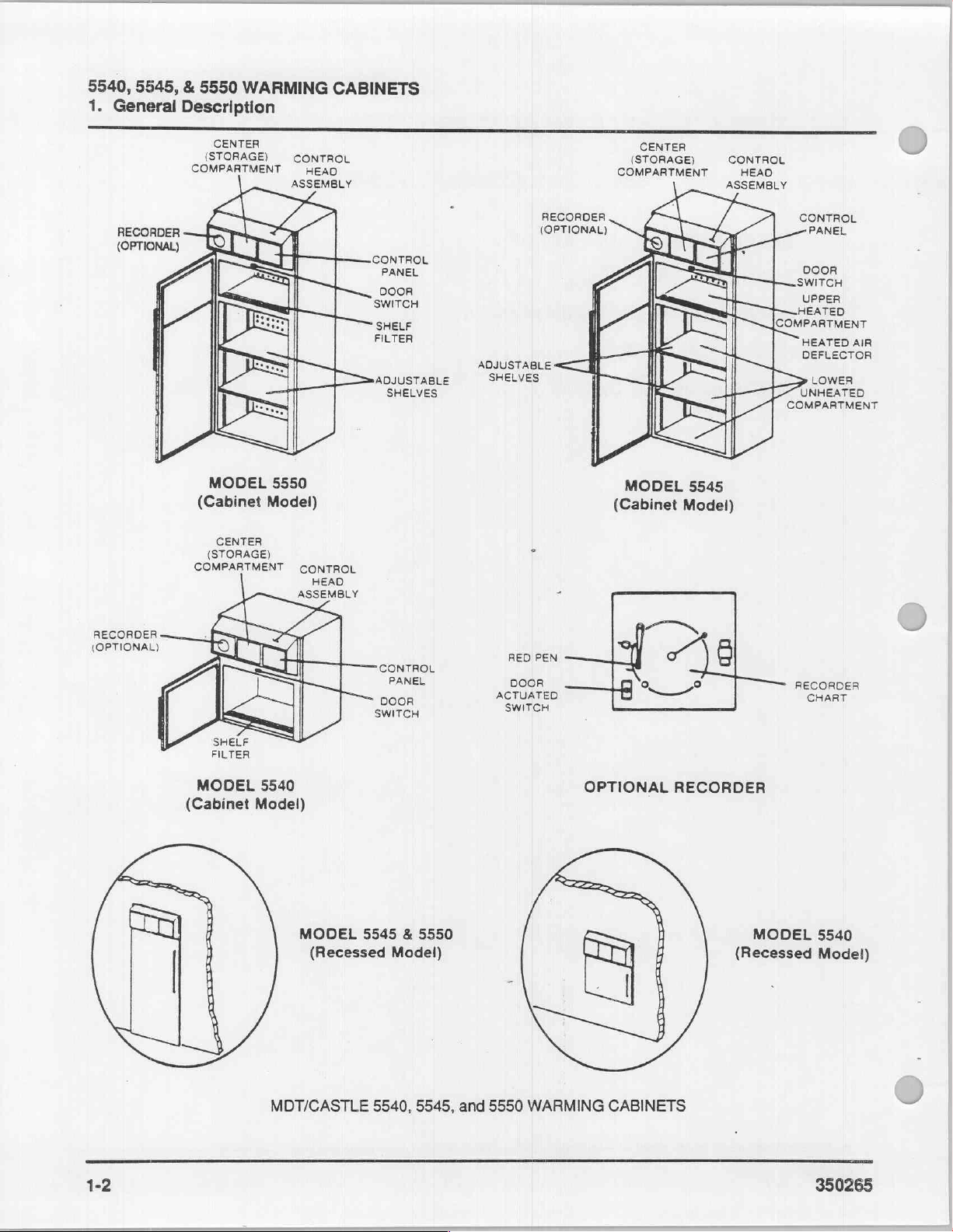
GENERAL
Castle
designed
kets,
is
The
partment
located
air
The
partment
adjustable
does
lower
regardless
The
over
is
provided
lower
provided
lower
DESCRIPTION
Door
Closing
switch
circuit.
shuts
Filter
Keeps
the
upward.
5540,
for
towels,
adjustable
compact
capable
in
the
and
directs
5545
Warming
and a lower
not
circulate
compartment
5550
Warming
items
placed
capable
of
are
three
in
shelves
Switch
the
and
Opening
off
electrical
airborne
heated
DESCRIPTION
5545,
and
the
heating and
and
other
dry
from
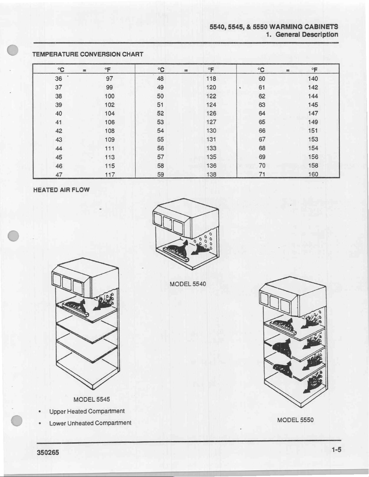
36°C
5540
Warming
of
holding
front
of
the
it
upward.
Cabinet
unheated
shelves.
of
the
holding
adjustable,
compartments
the top
and
warming
allows
compartment,
Air
into
remains
upper
Cabinet
on
each
20
two-liter
shelf,
directs
OF
COMPONENTS
cabinet
electrical
the
door,
power
and
dust
5550
Warming
storage
goods.
(97°F)
Cabinet
20
of
Cabinet
to
71°C
provides
two-liter
compartment,
has
an
upper
compartment
from
the
upper
the
lower
compartment,
at
ambient
compartment's
circulates
of
its
four
shelves.
flasks.
thus
allowing
to
be
adjustable.
filters
the
heated
it
upward.
door
depresses
power
to
contact
releases
to
the
debris
and
the
heating
circulating
from
directs
Cabinets
solutions,
temperature
(160°F).
one
flasks.
filters
Its
the
heated
heated
with
compartment
so
temperature
temperature.
heated
The
the
air
evenly
Each
two
shelves
height
The
air
from
of
the
the
heating
door
switch
circuit
and
through
heated
the
are
blan-
com-
filter,
com-
two
the
shelf
the
filter,
the
door
and
fan.
air
5540,
Optional
A
warming
recorde?
a
24
hour
DOOR
ACTUATED
SWITCH
Recorder
single
degree
over a 24
Door
Actuated
triggers
recorder
If
you
wish
recorder
switch
outward.
NOTE
|
5545, & 5550
Recorder
cabinet
to
record
period.
——8
OPTIONAL
Chart - The
increments
hour
period.
Switch - Closing
this
switch
door
triggers
to
record
door
is
open,
When
pen
and
will
door.
may
be
the
temperature
o
—
recorder
from 0 to
to
start
this
the
cabinet
simply
you
open
arm
automatically
moves
remain
WARMING
1.
General Description
equipped
o
of
CABINETS
with
an
the
cabinet
CHART
RECORDER
chart
is
graduated
100°C
(32
to
the
recorder
the
recorder;
switch
temperature
pull
the
to
the
until
you
to
holding
opening
stop
the
the
door
recorder
lifts
off
ramp
close
the
recorder.
while
door,
the
optional
over
in
212°F)
door
the
the
actuator
the
chart
where
it
recorder
en
Control
Center
be
May
cartridges,
pens,
350265
Head
Assembly
Storage
for
used
Compartment
access
ready
etc.
recorder
of
charts,
ink
Page 7
5540, 5545, & 5550
1.
General
Description
WARMING
CABINETS
Adjustable
(Models
To
increase
partments,
adjustable
Main
Turning
located
power
to
the
Transformer
The
transformer
to
provide
Overtemperature
This
switch
from
the
192°F,
Heaters
The
warring
ers.
These
sockets
Fans
Two
“Heated
5545
shelves.
Power
off
under
from
circuit
24V
heaters.
inside
fans
circulate
Air
Shelves
and
or
decrease
you
Switch/Circuit
the
the
the
control
breaker
for
closes
cabinet
heaters
the
Flow.”
5550
Only)
may
raise,
main
power
control
circuit.
output.
steps
down
the
chart
Switch
at
212°F
The
overtemperature
uses
screw
control
the
the
height
lower,
Breaker
switch/circuit
head,
removes
Power
the
electrical
recorder.
to
remove
two
500W
into
the
two
box.
heated
air
of
the
or
remove
all
is
still
electrical
switch
cone-type
middle
as
illustrated
three
com-
the
breaker,
electrical
present
power
input
power
resets
heat:
electrical
two
up
at
in
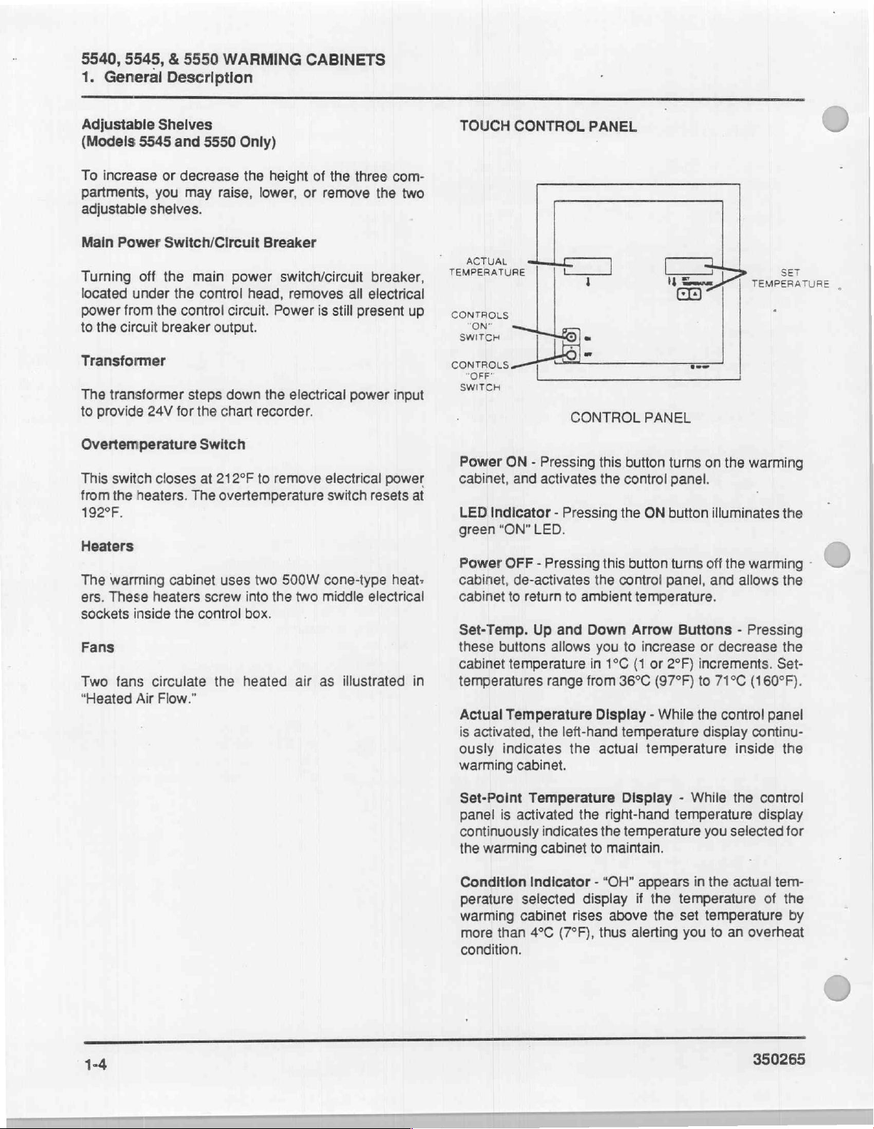
TOUCH
TEMPERATURE
CONTROLS
SWITCH
CONTROLS
"OFF"
SWITCH
Power
cabinet,
LED
green
Power
cabinet,
cabinet
Set-Temp.
these
cabinet
temperatures
Actual
is
ously
warming
CONTROL
| | ヒー
ON"
ON - Pressing
Indicator - Pressing
“ON”
OFF - Pressing
to
buttons
temperature
Temperature
activated,
indicates
LE
|
CONTROL
and
activates
LED.
de-activates
return
to
Up
and
allows
range
the
left-hand
the
cabinet.
PANEL
|
1
-
=
PANEL
this
button
the
control
the
ON
this
button
the
control
ambient
Down
in
from
temperature.
Arrow
you
to
increase
1°C
(1
or
36°C
(97°F)
Display - While
temperature
actual
temperature
İP
$
=
TEMPERATURE
CD
=
turns
on
the
warming
panel.
button
panel,
2°F)
illuminates
turns
off
the
warming
and
allows
Buttons - Pressing
or
decrease
increments.
to
71°C
(160°F).
the
control
display
continu-
inside
se
|
the
the
the
Set-
panel
the
Set-Point
panel
continuously
the
warming
Condition
perature
warming
more
condition.
Temperature
is
activated
indicates
cabinet
Indicator - “OH”
selected
cabinet
than
4°C
(7°F),
the
the
to
display
rises
thus
Display - While
right-hand
temperature
maintain.
above
temperature
appears
if
the
the
alerting
temperature
set
you
the
you
selected
in
the
actual
temperature
to
an
overheat
control
display
for
tem-
of
the
by
350265
Page 8
5540,
5545, & 5550
WARMING
1.
General Description
CABINETS
TEMPERATURE
HEATED
°C
36
37
38
39
40
41
42
43
44
45
46
47
AİR
CONVERSION
*
FLOW
=
SE
97
99
100
102
104
106
108
109
111
113
115
117
CHART
26
48
49
50
51
52
53
54
55
56
57
58
59
=
SE
118
120
122
124
126
127
130
131
133
135
136
138
°С
60
61
62
63
64
65
66
67
68
69
70
71
a
oF
140
142
144
145
147
149
151
153
154
156
158
160
*
Upper
‧
Lower
350265
MODEL
Heated
Unheated
5545
Compartment
Compartment
MODEL
5540
MODEL
5550
1-5
Page 9
5540, 5545,
General
1.
CONTROL
To
access
1.
Open
2.
Tum
control
3.
Raise
raised
4.
Tum OFF
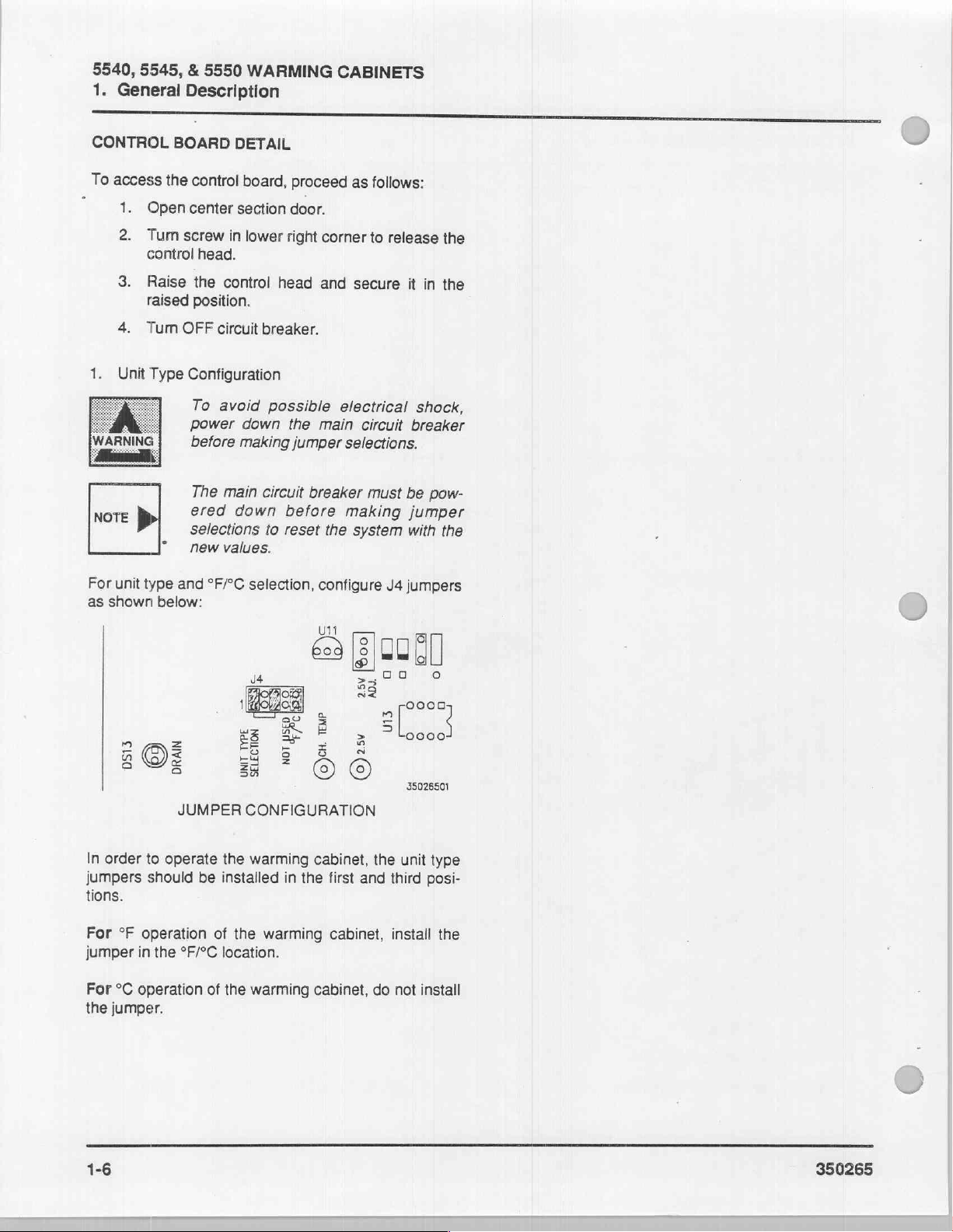
1.
Unit
Type
WARNING
NOTE
|
|
&
5550
Description
BOARD
the
control
center
screw
in
head.
the
control
position,
circuit
Configuration
To
avoid
Power
before
The
main
ered
selections
new
values.
WARMING
DETAIL
board,
section
down
making jumper
down
lower
right
head
breaker.
possible
circuit
before
to
reset
proceed
door.
corner
and
the
main
breaker
the
CABINETS
as
follows:
to
release
secure
electrical
selections.
making
system
circuit
must
it
be
jumper
with
the
in
the
shock,
breaker
pow-
the
For
unit
as
shown
In
order
jumpers
tions.
For
°F
jumper
For
°C
the
jumper.
type
and
below:
3
DS13
5
JUMPER
to
operate
should
operation
in
the
°F/°C
operation
°F/°C
125956
ES
EE
35
the
be
installed
of
the
location.
of
the
selection,
configure
UN
oa
=
+
5,
BSE
5
BS
©
CONFIGURATION
warming
warming
warming
cabinet,
in
the
cabinet,
first
cabinet,
J4
=
[8]
00
>50
0
RE!
|
5) > laces
the
unit
and
third
install
do
not
jumpers
(|
o
0008
2
35026501
type
posi-
the
install
1-6
=
350265
Page 10
С
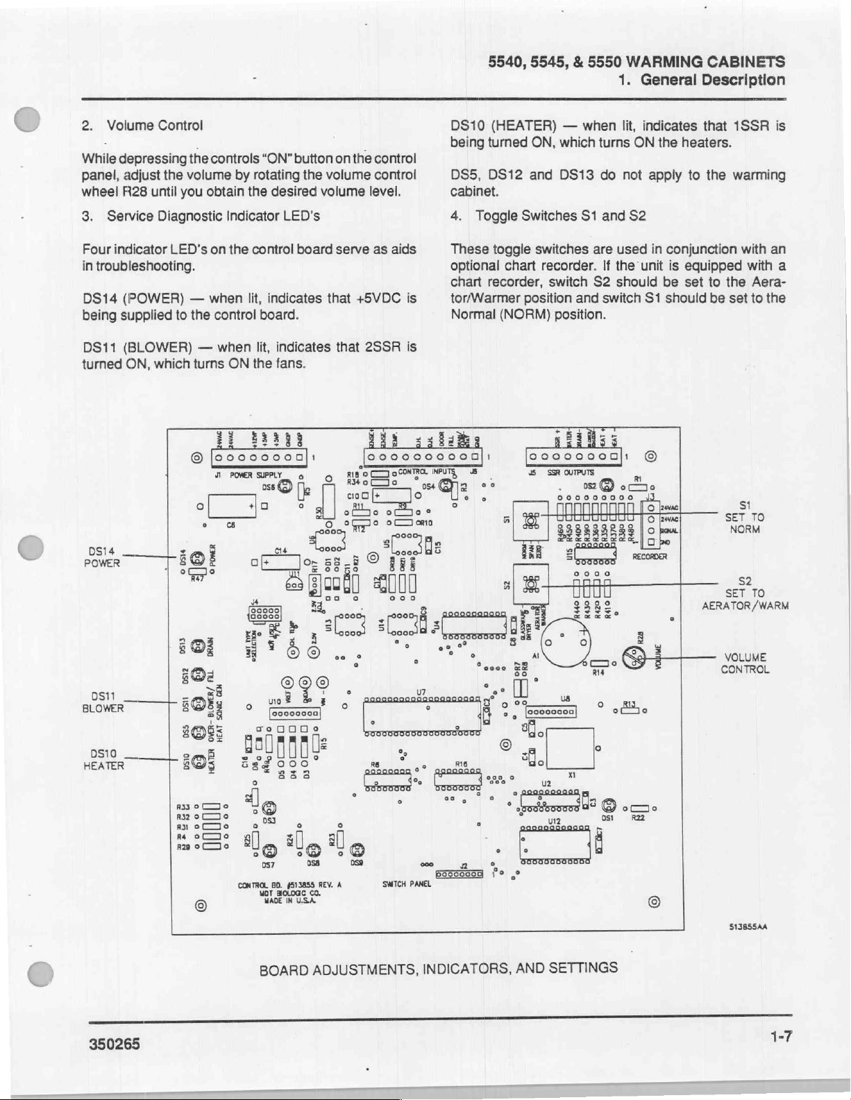
2.
Volume
While
panel, adjust
wheel R28
3.
Service
Four
indicator
in
troubleshooting.
DS14
being
DS11
turned
Control
depressing
until
Diagnostic
(POWER)
supplied
(BLOWER)
ON,
which
al
the
you
LED's
to
pnl
°°
the
controls
volume
obtain
on
—
when
the
control
—
when
turns
1
©
|ooooo000|:
q
οἱ
ㆍ
“ON”
by
rotating
the
desired
Indicator
the
ON
LED's
control
lit,
indicates
board.
lit,
indicates
the
fans.
O
do
a
um
Jo;
of
&
a
=
button
the
volume
volume
board
that
fi
o
|
Я
°
o
yi
Los
58-8
food]
3
dk
33,
on
the
level.
serve
+5VDC
that
2SSR
ΕΠΗ:
0000000000]!
no]
Bore
cio
оо
oro
®
i
E
С
control
control
as
aids
is
is
ocoNTRO
+
обще»
ooo
A:
Е
BE
2000
2
DS10
being
DS5,
cabinet.
4.
These
optional
chart
tor/Warmer
Normal
INPUT
Oz
°
y
:
5540, 5545, & 5550
(HEATER)
turned
DS12
Toggle
toggle
chart
recorder,
(NORM)
—
ON,
which
and
DS13
Switches
switches
recorder.
switch
position
position.
Gil;
00000000)
o o
点
ος
45
ζω]
5
=
FRE
s
x
FI
SSR
OUTPUTS
.
0060000000
ΠΠΠΠΠΠΠΠΠ
HHHHHHHHH
22322585
НЕЕ
se
when
turns
do
S1
are
S2
and
O
oooo
ロロ
ロロ
0000
9382,
WARMING
1.
General Description
lit,
ON
not
and
S2
used
If
the
unit
should
switch
indicates
the
apply
in
S1
©
that
heaters.
to
conjunction
is
equipped
be
set
should
Do
µε
{ο
eme
Го
[o
ecooa
AERATOR/WARM
.
CABINETS
1SSR
the
warming
with
with
to
the
Aera-
be
set
to
st
TO
SET
NORM
s2
TO
SET
is
an
a
the
0511
_
BLOWER
0510 — o
HEATER
350265
à
>
802.
l
oi
mi
si
e
호
so};
SOR
|
205
6033
ㅇㄷㅇ
032 ㅇ ㄷ ㅋ ㅇ
ryote
moe:
©
emi
no)
«ορ
isd
o
a)
05
©
İş
o
DS7
CONTROL
BD.
Mahe
BOARD
몰
e
ilç
o
058
[513855
REV.
UA
ADJUSTMENTS,
a
il
©
o
059
À
SWITCH
осо
PANEL
2
INDICATORS,
erim
[
pores
2
u
ğ
©
*
ci
ca
i
SETTINGS
AND
VOLUME
CONTROL
513855AA
1-7
Page 11
5540, 5545,
General
1.
NOTES
&
5550
WARMING
Description
CABINETS
350265
Page 12
5540,
5545, & 5550
WARMING
2.
Wiring
CABINETS
Diagrams
5540/5545/5550
PRINTED
CIRCUIT
SECTION
WARMING
BOARD
2.
WIRING
CABINET
SCHEMATIC
WIRING
DIAGRAM
DIAGRAMS
DIAGRAM
......
........
2-2
2-6
DIAGRAMS
WIRING
2.
SECTION
350265
2-1
Page 13
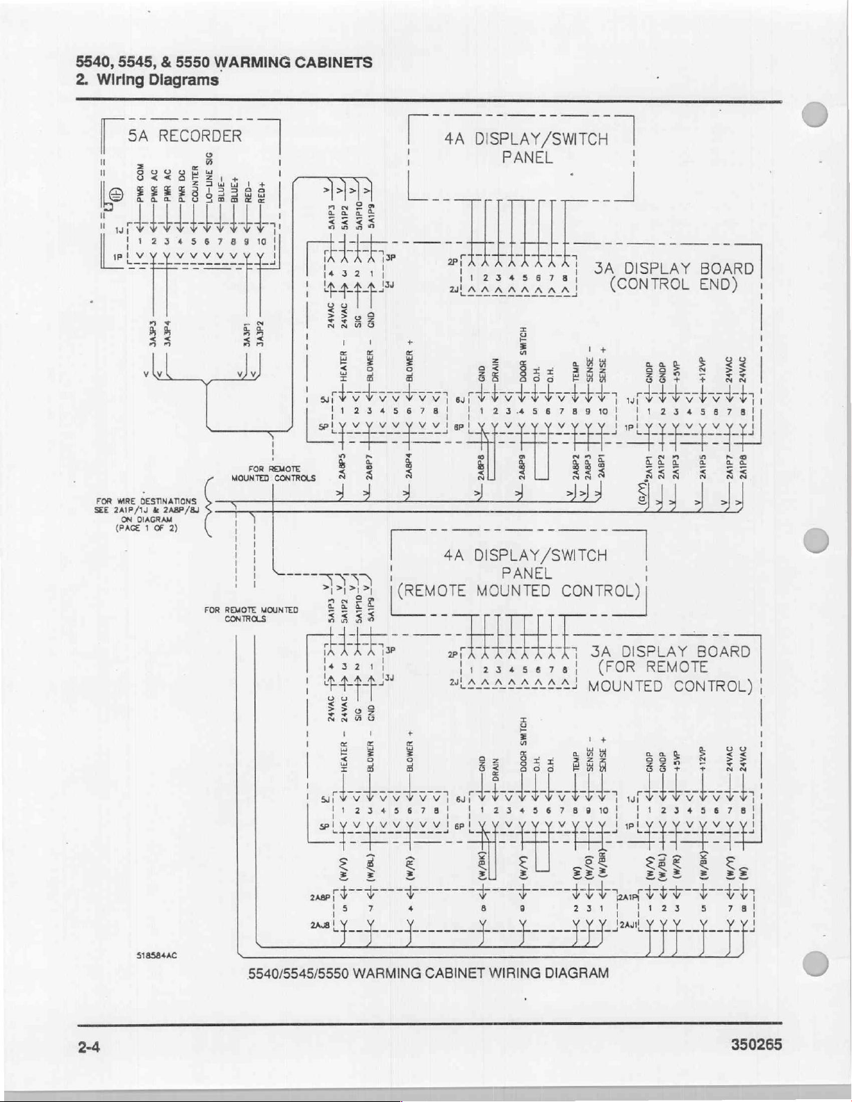
5540,
2.
Wiring
5545, & 5550
Diagrams
WARMING
CABINETS
©
PE
1
i
1HTR
a
1
Г
1
i
|
|
1
1
Rİ
©
1
|
MAC
LR
ote
i
RE
|
|
|
1
we
mm
ep
R
zome-、
1CB
BU
er ae
2A2ssRs
=.
nr
2AiC83
2A2TB10 十 15
Ca
2TB
u
2
4
=
LE
a
X
a
[ek
9
10
ami
Cron
mm
Е.
von
]
[ls
A]
L
2A1TB2
En ae
a
2A1PSIPS
моек
2A1T4
2A1Fu2
am
24175 © に
AMRS
rem В |
|
| |
|
2SSR
|
RIR
]R
Bu BE
ssa
ca
30
à
=
2
15585
10
DE
2A3HTR
2A4HTR
トー
2HTR SHTR
ет
oe
ーー ーー ae
Naam
>
BR
№
E
—0
(W
(ゆめ
em
cl
RR
353
Sy
1
zů
eee
—
Da
—
29)
=
W
N
242785:
ateo?
ζω,
ATE!
00.
2A2TB
E
2
1SSR
m
(I
2A
CONTROL
R
242782
EK 2 A2FU1
1FU
ana
я
5
2A8J4
2A8J5
call
=
vel
5h>
[418
3
`
2A1PS1P3
-алатаз
Г
7
8
3o-
<
—
PUM
aK
リア
αν
2A4HTR
ohN9
2A1HTR
-一 一 2Aic85
mi
2A2TB3
Ex
A
Ass
EN
Eu
に
POWER
E
SUPPL
ーー
BOX
ーー
(PS.
ый
2d2e
+1
[2]
+05]
-v[6]
Fi
=
2FU
2A2TB8
90
O
m
24147
wm プ 3Pr 大 大 大 4PT た た]
Mm
518584AA
on
E
z
Ê
aaa
‘yaa!
i
SU
qu
vi vi İv
533
きき
if
È
Vas-
[24143
[as
a
___
È
14]!
DASE
3
|
7
F-
|
um
1
i
|
|
|
|
|
i
|
I
|
|
i
A
À
iy
sg
5
3
aa
dizi
7
viv
23
きき
|
5540/5545/5550
2-2
WARMING
CABINET
WIRING
DIAGRAM
Page 14
2A2HTR
nr
R
4HTR
2F
=
--
2A2HTR
ーー
2AISSR2 一 ak
ーー
F
2A2TB10
ZA1SSR2
2A2T810
2A2SSR4
2A2TB9
ーー
BK
Y
=
an
ーー
©
r 1
5540,
R
—R
вк
一
NOTES:
1)
2)
3)
|
4)
=
E]
i
1
5)
8)
7)
5545, & 5550
ALPHA
NUMBERS
BRACKETS
TO BE
STAMPED
THE
WIRES
STAMP
AS
120V = R
NEUTRAL
LOW
VOLTAGE = У
INFORMATION
JUMPER
STRIPS
120
VOLT
MRING
CONNECT
WIRE
()
INDICATE
WILL
BE
FOLLOWS:
=
AS
FURNISHED
NUT
3
SHOWN
ON
WIRE.
STAMPED
RED
MARKING
BK
NOTED
SHOWN,
TO
TO JA
SEE
ON
WIRE
ACTUAL
THESE
WITH
BLACK
MARKING
VIOLET
ON
LABEL
WTH
FOR 240
UNUSED
DISPLAY
PAGE 2 OF
WARMING
2.
Wiring
LEADS
PART
WIRE
COLOR,
MRES
ARE NOT
THE
“APPLICABLE
ON
WHITE
MRE
ON
MARKING
ON
ON
BOTTOM
TERMINAL
WIRE.
VOLT
BOARD
2
BLOCK.
MRING
CABINETS
OF
HOT
NOT
INFORMATION
STAMPED
WHITE
MRE
WHITE
SIDE
SEE
Diagrams
STAMPING
COLORED
MRE
OF
1TB
DETAIL:
A
|
ss
ipo
一 一 一
eV
fy 出 二
1
RE
(Mv
一
gam
zie
545
yy
YY ツマ VI
LS
233
Ве
さき
ささ
VI
3A6P8
3A6PID
『
D
©
<+
=
c
œ
(===
1
Y
&
Я
4
à
る
weps
ト
人
和
<
e
©
—{<
—İ<
MY
Re
ЕЁ.
35
re
=
ささ
34506
는
1
М5Р!
<
<
è
и
1
<
すく
«ος
し
ARTE
ele
1
(P
а
MÉ
@)
3Α5Ρ5
«ἰ-
3AGP1
で
m
ie
—+<
la
을
x
Φ
34604
<T-
©
—<
enna
alae
=
=
m
ES
5
882
Sais
EBE
ЕЯ
SES
um
Lo
1
由
1
1
1
|
i
1
!
ㅣ
E
AERATOR
UNITS
ONLY
R
2A3P1
а
24303
ο
“一
2A4p2
1A_POWER
GR
241781
トー
2Aimms
>
1SW
τὸ
182
1TB
ITS
==
><)
=
c
Ma
SUPPLY
|
NA
120/240V
SUPPLY
-
LINE
350265
2A3J1
<
<
1
24343
ЗАЗ
< < <
1
2A1SSR3
2A1SSR4
1
1
2442
zm
2А25582
2401
<
S
<
~
È
5540/5545/5550
WARMING
518584АВ
CABINET
WIRING
DIAGRAM
2-3
Page 15
5540,
2.
5545, & 5550
Wiring
Diagrams
WARMING
CABINETS
ここ
===.
ニー
His
@,
=
2
5
Sabe
бы
Sy
woo
ov
ma
>
&
-
>!
serve
yi
5388
eR
2830
oy
518584AC
WALNNOD
ov
owa
MdA
—>
一
w
2
0
>
>!
개
|!
parve
88,
ua
SIS
INN-OI_l>
‘amato
n
o
>!
3!
хм
sv
é
e
~~
ER
mbe:
a
Tps
>
sos!
o
>
m
ii
¡deve
ны
3
2
レト
ーーーーーーーー-
3
98
oF
=
age
a
2
ŞE
88
9
)
3
1
!
i
È
a
a
В
a
5540/5545/5550
Edive
zdlys
TH
4L<
-THT<
+
9
の
<
«L
<4—
ovasz
ovArz
98
-
alvaH-
bal,
BERN
ラ
>
ー
>
オーcdmve
|
Nİ
LE
as
o
cave
er.”
НЕ
|<
M
+
<
<|-
эми
OVA
—
VVS
Deli
43
—
>-
WM)
>
33
0
>
WARMING
ua
十
Da
|
ce
-
<t—
흐
ano
-
yoe
下
i>o
1>
PP
”>
<
>!
>
1
deve
x
L
CE
ÈS
me
H<
ias
ÇÜ
—
«ian
-
знову
>
e
E
>!
>
(18/M)
Pr
|
>
|
La
i
0
+
mole»
Des
I>n
wo
>|
>I
dove
n
|
il
o
을
|
i
MIMO
—İ>
peg
Dr
©
>-
(WM)
P
!
SO
+
>
|
CABINET
+
1
に
이
a
ww
ec
É
yi
|
|
<
」
t<
ヒーーー
—
ニ
J
<I
2
-4
оу
<
Ly
y
а
LS
2
as
gı
|
1
1
o
>
=
=
Sel
ic
Муна
ano
>
м
>!
save
!
o
O.
o
3
-=
-<<
aa
SI
m—p
Nvua—+>
-
6
>
===>
Fan
-
|
©
HA
i
WIRING
su
2
Ga
<
4
HA
Hed
더
을
I<
n<l
xl
<I
HOLWS
80000
mo
Hols
ban
a
à
of
1
SL!
sdgvz
M
Nİ
i
I
SUA
4
マラ
ZE
о
mrk
HK
ded
pre
lew
<
<i
19
a
west]
ob
bel!
1
>
tl
wo
|
1
起。
>
|
1
|
DIAGRAM
=
은
fo
=
SNS
ara
>
=
a
EL
coeve
20068
-
一
시
i
©
=
z
!
ーーーー
=
ュ
-
ssNds
di
+>
15
o
w
>
(0/0)
の
や
>
>]
|
T
==
|
|
!
LE
no
=
OS
+anst>
Ea
a
를
©
>
|
r
=
GB
o
E
|
4
1955
|
se
GK
F
=
+
35N
—I>
n
Lt
2
2
>
a
uen
on
-
A
RN
2
y
I
SISI
の
<O
Pe
ast—t>
oo
dano—t>
一
I>*
>
©
—
m
>
cave
dI
>
вам
ινε
τη
AN]
一
人
ーー
1
JU
a
3
Cw
a
o
©
ded»
da
dm
一
<>
1>
已 -
+
n
E
HI
>
>
t+
teva)
wm)
ws)
τος
ba
+>
AS
E
sn
Е
i
i
Ip
O
mu
9vAvz
Att
>
一
booli
>
~
n
>
4010
i
Sdivz
|
1
го
mp
<
É
0
그
oz
dz
一
—>
>
e
に
B
>
トー
>
мун)
Wm
+>
©
n
m
>
一
E
OMZ
>
원
=
VE
>
©
=
>=
o
=
-m
===
]
SE
=
=
+
2-4
350265
Page 16
5540,
5545, & 5550
WARMING
2.
Wiring
CABINETS
Diagrams
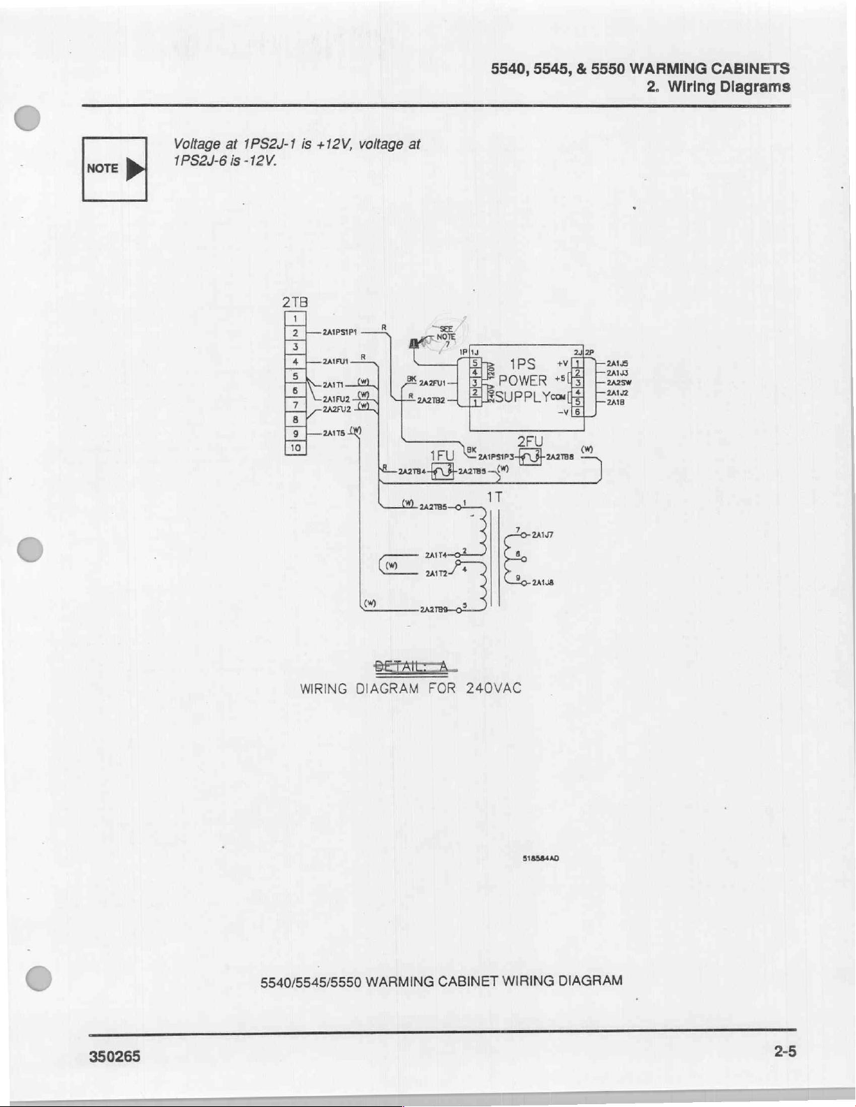
NOTE
>
Voltage
1PS2J-6
at
1PS2J-1
is
-12V.
is
+12V,
voltage
at
Ш
5
1PS
4
POWER
digo
2422
+
+803]
$
2A1J2
6
WE
2A1J5
Dias
2418
rem,
WIRING
DIAGRAM
2A2
FOR
ES
240VAC
518584AD
(
350265
5540/5545/5550
WARMING
CABINET
WIRING
DIAGRAM
2-5
Page 17
Cc
N
74LS373
50
の
—
s
о
+
a
o
o
+50
SUPPLY.
on
2-6
+5№
Sed
ich
d
ES
2
ad
4
|
ATF
9
n
“ae >
1-8
LL
4
è
Ot
o
AF
]
$
9
av
PRINTED
‘i
é
a
어
고
싸
CIRCUIT
내
© o
es
|
©
어
그
싸
어
c9
그
싸
BOARD
los
그
싸
어
SCHEMATIC
마사
ㆍ
‘Gone
iz
DIAGRAM
5-4
+6\0
+5\А
RM
Bi
|
Y
RIS
18
M
=25
G)
CON
R33 る jk
54-14
Nara
ao
ος
개
66
우
dos
서 세
—
ZIK
328
|
q
To
350265
51840384
5
D
ㅅ
Page 18
人
ESSA
一
мЙ——
一
一
re | ne
[121
13
一
16
Las | rel
2
|7
一
一
re
Lats
12
а|
RIO
썼
5
2 4
и
+
9
————<
Vo
02
U6
715
o
e
$
+50
:
04
05
Lz
이주
1N5409
€
+
me
126
44
pa
PL
|,
mma?
an
sl
зак
vara
|
uo
RIGHT
DISPLAY
vss
y
+svo
RIS
1.2K
İZ
de
ax
|.
εκ
DISPLAY
|
|
J
z
+SVA
8-3
πα
M
ua
44
49
es
Vo
5
16
一
di
из
410
2:
m
та
το
US
mS
и
pa
5
lea
[^^
|3_
sir
sin
CCN
É
ca
,
Co
OOF
is
wt
PRINTED
8
<
Da
CIRCUIT
BOARD
SCHEMATIC
=
ee
350265
DIAGRAM
24VAG
———
ap
ош
24VAC
3-3
31840388
2-7
Page 19
5540, 5545, & 5550
2.
Wiring
|
NOTES
Diagrams
WARMING
CABINETS
2-8
Page 20
5540, 5545, & 5550
WARMING
3.
Trouble
CABINETS
Analysis
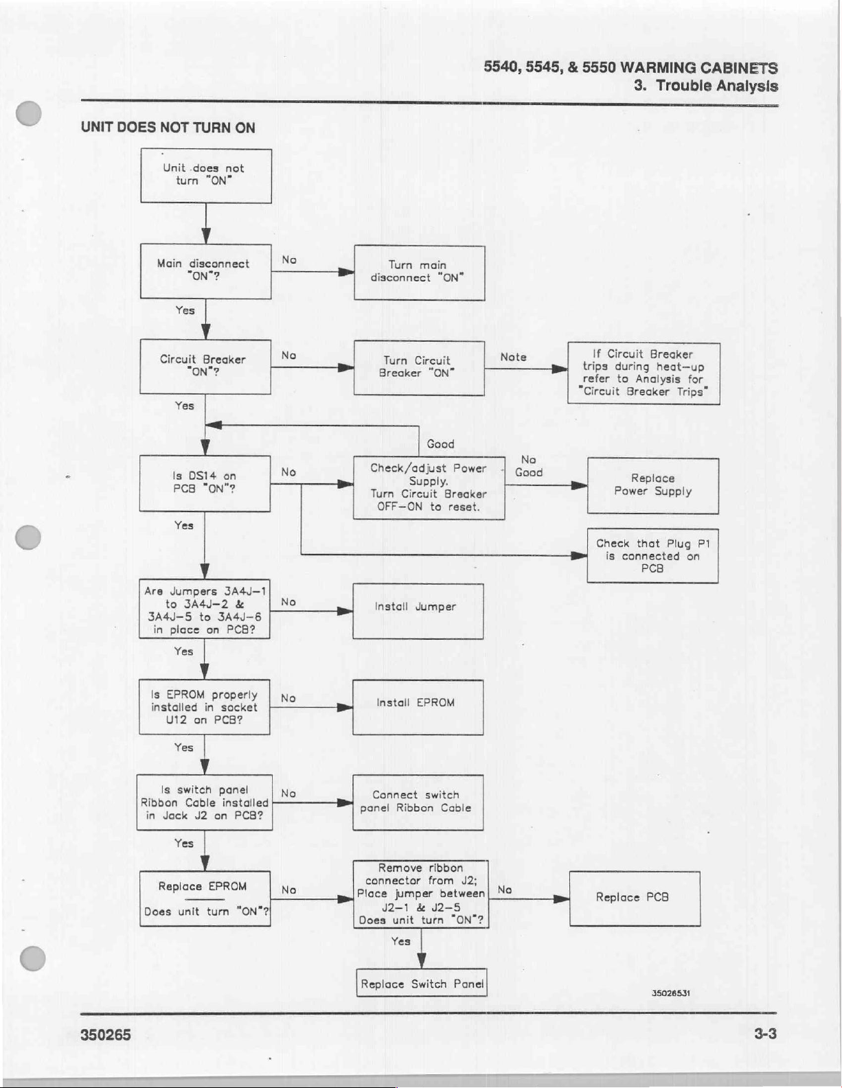
DIAGNOSTIC
Unit
Circuit
UnitiDoos
Unit
+5V,
“OH”
Temperature
“OH”
Temperature'Display
HEATER/FAN
SECTION
FLOW
Does'Not
Breaker
Not
At
+12V
Warning
Warning
OPERATIONALCHECKS
CHARTS
Turn
Trips
NobHeat
Proper
Power
Indicated
Display
Indicated
Temperature . ..,.............
Supply
3.
TROUBLE
..........
On
..........,.........
ee
Check
In
Actual
ls
In
Set-point
e.)
................
sad.
e
..............
ANALYSIS
κ ο ενος
ea
a
e e
laa
e
it!
Sl
e
e
ος
...34
9
ὃν ο o
3-10
3-2
3-3
3-5
3-6
3-7
3-8
3-9
ANALYSIS
TROUBLE
3.
SECTION
350265
3-1
Page 21
5540, 5545,
3.
Trouble
TROUBLE
&
5550
WARMING
Analysis
ANALYSIS
CABINETS
DIAGNOSTIC
FLOW
ELECTRICAL
of
control
Power
should
sonnel
the
trouble
CHARTS
box
activated.
be
and
SHOCK
analysis
components
This
conducted
extreme
with
HAZARD.
requires
with
trouble
qualified
by
caution.
Some
access
main
the
analysis
per-
to
3-2
=
350265
Page 22
C
UNIT
DOES
NOT
Unit
turn
TURN
.does
"ON"
ON
not
5540,
5545, & 5550
WARMING
3.
Trouble
CABINETS
Analysis
Main
disconnect
“ON”?
Yes
Circuit
où"
Yes
Is
DS14
PCB
Yes
Are
Jumpers
to
3А4/-2
3A4J-5
in
place
Yes
4
|
Breaker
ON
?
on
し
ON
3A4J—1
to
3A4J-6
on
|
?
&
PCB?
No
No
—
fm
No
№
>
Turn
Turn
Circuit
Breaker
eck/a
Circuit
Jumper
main
"ON?
Good
EN
disconnect
Check/adjust
Turn
OFF—ON
Install
“ON”
"ON
e
Breaker
to
reset.
P
Su
—
er
Note
Good
——
Ja
>>>
refer
"Circuit
>
Check
B
о
to
Breaker
Replace
Power
is
connected
Analysis
Trips”
Supply
that
Plug
PCB
e
for
P1
on
Is
EPROM
installed
U12
hi
ibbon
in
Jack
Replace
Does
Yes
Cable
Yes
unit
properly
in
socket
on
PCB?
|
은
p
installed
J2 on
|
EPROM
turn
x
PCB?
"aw
"ON"?
No
-}—————_B>
No
—2
No
install
ROM
Connect
M
Remove
connector
po
Place
42-1
Does
Replace
|
Ribbon
jumper
unit
Yes
switch
Cabl
ribbon
from
between
&
J2-
turn
|
Switch
SES
J2;
“ON”?
Panel
늘
.
Replace
PCB
men
Page 23
5540, 5545, & 5550
3.
Trouble
Analysis
ARMING
W
CABINETS
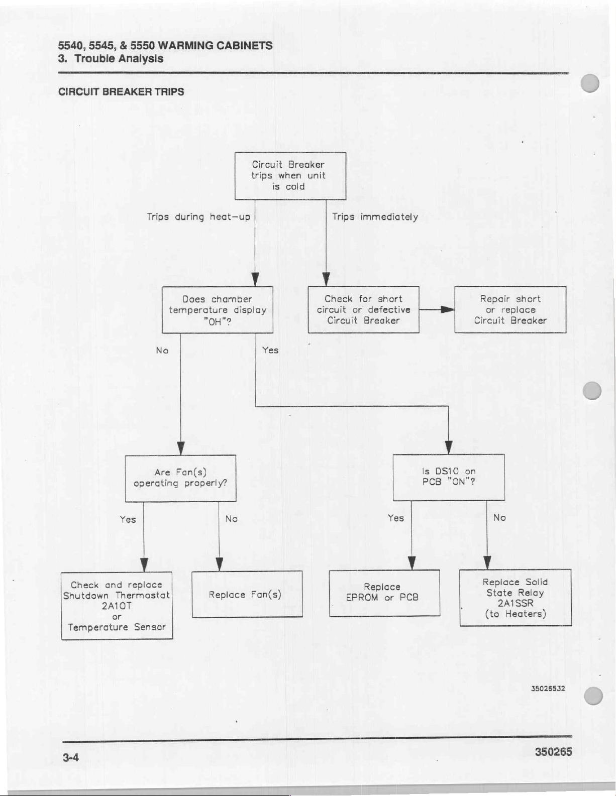
CIRCUIT
BREAKER
TRIPS
Trips
temperature
No
during
Does
heat-up
chamber
"OH"?
Circuit
trips
display
Breaker
when
is
cold
Yes
unit
Check
circuit
Circuit
Trips
immediately
for
short
or
defective
Breaker
——B»
Repair
or
replace
Circuit
short
Breaker
Check
Shutdown
Temperature
operating
Yes
replace
and
Thermostat
2A10T
or
Sensor
Are
Fan(s)
properly?
No Yes
Replace
EPROM
Replace
Fan(s)
or
PCB
Is
PCB
DS10
on
"ON"?
No
Replace
State
2A1SSR
Heaters)
(to
Solid
Relay
35026532
3-4
350265
Page 24
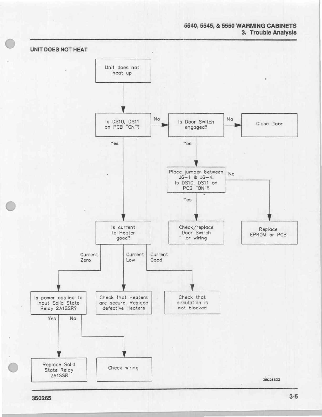
UNIT
DOES
NOT
HEAT
Unit
heat
19
0910,
on
PCB
Yes
does
not
up
ost | №
"ON"?
Place
5540,
5545, & 5550
ls
Door
Switch | №
engaged?
Yes
jumper
J6—1 & ὁ6--4.
Is
DS10,
PCB
Yes
between|
DS11
"ON"?
on
re
No
WARMING
3.
Trouble
CABINETS
Analysis
a
Is
Input
power
Relay
applied
Solid
2A1SSR?
Yes
Y
Replace
State Relay
Solid
2A1SSR
State
No
Current
Zero
to
Check
are
defective
Is
current
to
good?
that
secure.
Check
Heater
Current | Current
Low
Good
Heaters
Replace
Heaters
wiring
Check
/replace
Door Switch
©
or
wiring
Check
circulation
not
that
blocked
is
ai
35026533
350265
Page 25
5540, 5545, & 5550
3.
Trouble
UNIT
NOT
Analysis
AT
PROPER
WARMING
TEMPERATURE
Calibrate
&
per
CABINETS
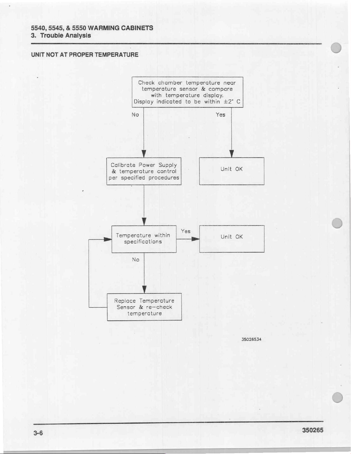
Check
Display
No
Power
temperature
specified
chamber
temperature
with
temperature
indicated
Supply
control
procedures
temperature
sensor & compare
display.
to
be
within
Yes
Unit
near
+2°
C
OK
Temperature
specifications
Replace
Sensor
temperature
No
Temperature
&
re—check
within
Yes
Unit
OK
35026534
3-6
350265
Page 26
5540,
5545, & 5550
WARMING
3.
Trouble
CABINETS
Analysis
C
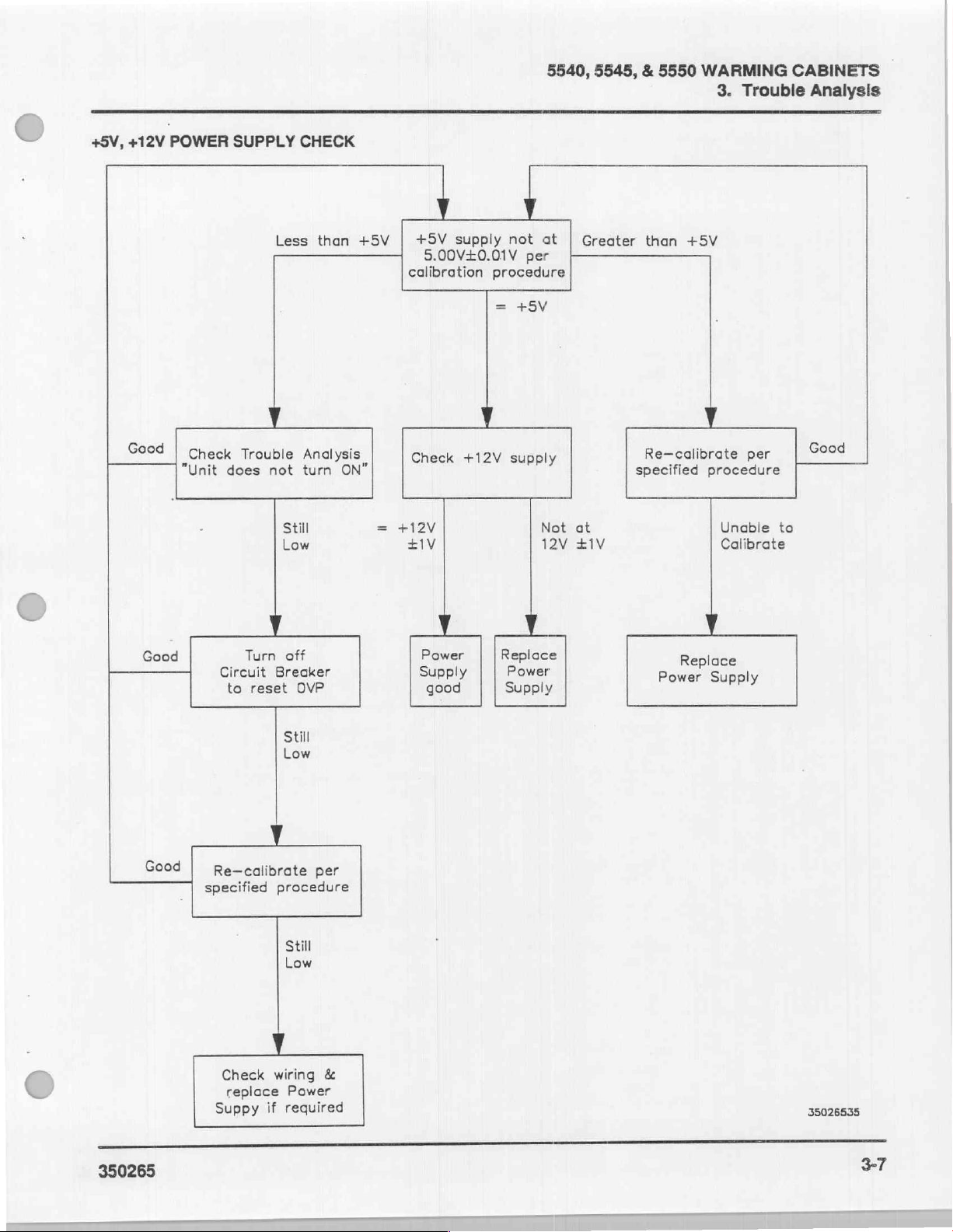
+5V,
+12V
Good
POWER
Check
"Unit
SUPPLY
Trouble
does
CHECK
Less
than
Analysis
not turn
Still
Low
+5V
ON”
+12V
+5V
supply
5.00V+0.01V
calibration
Check
士
+12V
1V
not
at
per
procedure
=
+5V
supply
Not
12V
Greater
at
+1V
than
Re—calibrate
specified
+5V
procedure
Unable
Calibrate
per
to
Good
4,
Good
Good
350265
Turn
Circuit
to
reset
Re-calibrate
specified
Check
replace
Suppy
off
Breaker
OVP
Still
Low
procedure
Still
Low
wiring
Power
if
required
per
&
Power
Supply
good
Replace
Power
Supply
Replace
Power
Supply
35026535
3-7
Page 27
5540, 5545, & 5550
3.
Trouble
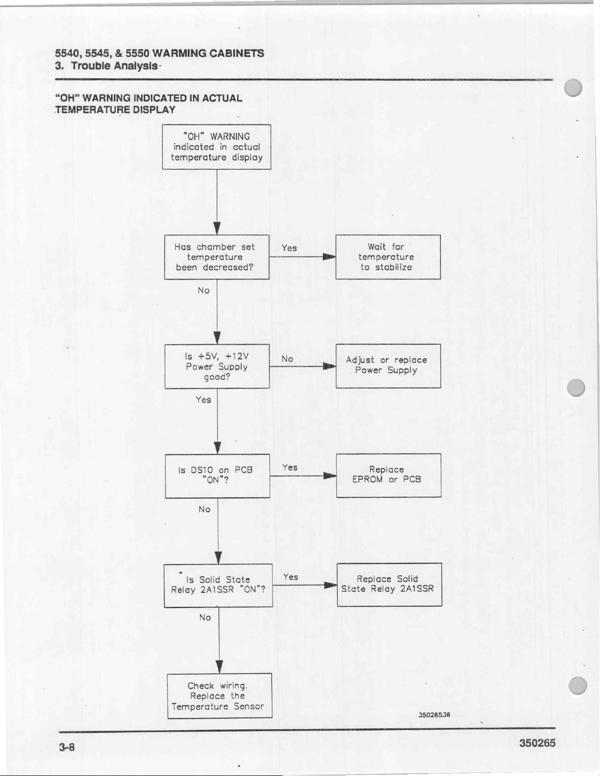
“OH”
WARNING
TEMPERATURE
Analysis-
INDICATED
DISPLAY
WARMING
"OH"
indicated
temperature
Has
temperature
been
CABINETS
IN
ACTUAL
WARNING
chamber
decreased?
No
in
actual
display
set
Yes
Wait
for
temperature
to
stabilize
Relay
Is
Power
Yes
Is
DS10
“is
+5V,
+12V
Supply
good?
у
on
"ON"?
No
Solid
State
2A1SSR
No
PCB
"ON"?
No
Yes
Yes
Adjust
State
Power
Replace
EPROM
Replace
Relay
or
replace
Supply
or
PCB
Solid
2A1SSR
38
Check
Replace
Temperature
wiring.
the
Sensor
35026536
350265
Page 28
€
_
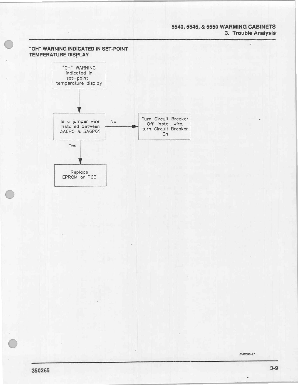
“OH”
WARNING
TEMPERATURE
INDICATED
DISPLAY
"OH"
indicated
set—point
temperature
Is a
installed
JA6PS
Yes
WARNING
jumper
between
&
3A6P6?
IN
in
display
wire
SET-POINT
No
Turn
Off,
turn
Circuit
install
Circuit
On
5540,
Breaker
wire,
Breaker
5545,
€:
5550
WARMING
3.
Trouble Analysis
CABINETS
Replace
EPROM
or
PCB
350265
35026537
3-9
Page 29
5540, 5545, & 5550
3.
Trouble
Analysis
WARMING
CABINETS
HEATER/FAN
n
Check
button
and
close
Using
the
tons,
select a temperature
the
chamber.
DS11
and
(PCB)
should
on;
and
Open
the
out
(off).
Close
the
Check
a.
Using a digital
age
should
120
b.
Check
amprobe
door
mately
or 0.1
OPERATIONAL
that
the
circuit
in
the
lower
the
door.
set-temperature
DS12
on
the
be
lit.
DS11
DS12
indicates
chamber
chamber
the
fan’s
door.
door.
electrical
voltmeter
across
or
closed,
be
OVAC
240VAC
the
current
on
0.2
amps
amps
2A2TB10
2A1F
the
on a 240VAC
CHECKS
breaker
left
corner
up
that
display
indicates
that
the
DS11
supply
(DVM),
and
with
the
with
the
door
through
and
2AF2.
amperage
on a 120VAC
is
ON.
Press
of
the
control
and
down
requires
printed
that
heaters
and
DS12
circuit:
check
2A2SSR4.
door
open,
closed.
2A2SSR4
With
should
electrical
electrical
the
panel
arrow
heat-up
circuit
board
the
fans
are
on.
should
the
Voltage
and
either
by
placing
the
cabinet
be
approxi-
supply
supply.
ON
but-
of
are
go
volt-
Check
a.
b.
the
Using a DVM,
2A2TB10
VAC
with
VAC
with
Check
amprobe
cabinet
8.5
amps
amps
heater
the
on a 240VAC
and
the
the
current
on
door
ona
2A4HTR
electrical
2A1SSR2.
door
door
closed,
120VAC
supply
check
open,
closed.
through
and
the
electrical
electrical
circuit.
the
voltage
Voltage
and
either
2A1SSR2
2A3HTR.
amperage
supply.
should
120
by
With
should
supply
across
be
0
or
240
placing
the
be
or
4.25
3-10
350265
Page 30
5540, 5545, & 5550
4.
Calibrations
WARMING
and
CABINETS
Adjustments
SECTION
POWER
TEMPERATURE
CHART
DOORADIUSTMENIT
SUPPLY
RECORDER
4.
CALIBRATIONS
VOLTAGE
CONTROL
CALIBRATION
O
CALIBRATION
CALIBRATION
.................
AND
ADJUSTMENTS
.............
.............
NN
4-2
4-2
4-3
4-4
.
ADJUSTMENTS
AND
350265
CALIBRATIONS
4.
SECTION
4-1
Page 31

5540, 5545, & 5550
4.
Calibrations
and
WARMING
Adjustments
CABINETS
CALIBRATIONS
POWER
SUPPLY
The
electrical
To
personal
contact
adjustments
1.
Raise
the
control
2.
Remove
head
omponents.
3.
Check
button
and
stabilize
bi
NOTE
+5
4.
a.
b.
the
assembly
oe
that
the
in
the
let
the
for
The
conducting
Adjustment:
Volt
the
Place
positive
the
Adjust
supply
+5.00+0.01
NOTE
№
The
tom
head
adjustment.
AND
ADJUSTMENTS
VOLTAGE
power
prevent
with
CALIBRATION
circuit
adjustments
possible
injury,
the
and
head
assembly
three
screws
for
access
circuit
breaker
lower
left
corner
temperature
15
minutes.
control
DVM
probe
+5V
the
until
adjustment
of
panel
ing
callorati
calibrations.
negative
3A1P3
on
adjustment
reading
the
the
on
VDC
power
the
screw
driver
must
be
ON
to
and
calibrations.
electrical
do
not
electrical
shock
make
personal
circuit
calibration.
cover.
that
in
secure
to
the
is
ON.
of
the
the
warming
must
probe
of
pot
power
be
on
the
on
the
Press
the
control
cabinet
ON
prior
3A1P1
PCB.
the
on
DVM
the
meter.
pot
is
located
supply.
is
at
small
A
required
the
for
make
and
during
power
supply
ON
panel
to
and
power
is
bot-
flat
this
TEMPERATURE
1.
Calibrate
Supply
Temperature
ноте
>
2.
5
E
な <
a
=,
Adjust
a.
Connect
GNDA
using
b.
Adjust
a
È
ES
do
©:
Me
2.5
. .
DVM
202
=
=
©:
=
E:
sa
CONTROL
the
power
Voltage
Calibration”)
Control
The
control
conducting
VDC
on
the
the
DVM
and
the
test
R17
reading
positive
clips.
(2.5V
of
af
29900
ae
=
+
ss
に 8 8
©
zá
ina Β So
o
CALIBRATION
supply
Calibration.
voltage
panel
must
before
be
(see
making
ON
calibrations.
PCB:
negative
adjust),
2.500
5
=
(o
©
probe
to
probe
to
test
point
. . ,
if
required,
+0.005
os
558-8
AGG
33
2
3
@——
to
VDC.
É
0
[
0000
*
SG
Li
~
“Power
the
-
prior
to
test
point
2.5V,
provide
ADJUST
R17
4
PROBE
ae
02022
42
TEMPERATURE
CALIBRATION
ADJUSTMENT
VOLTAGE
350265
Page 32

5540, 5545, & 5550
4.
Calibrations
WARMING
and
CABINETS
Adjustmenis
CHART
NOTE
The
RECORDER
lb
pen
is
hysteresis
calibration
been
ON
C8
GLASSWARE
DRYER
AERATOR
WARMER
SER
RECORDER
This
qualified
Recorder
initial
there
Always
and
printed
tion
calibration.
Calibration”
Calibration”).
calibrated
or
linearity
should
for
at
least
be
-
|
CALIBRATION
calibration
should
service
calibration
installation,
is a major
ensure
recorder
that
circuit
BEFORE
(See
and
for
NULL
adjustment
attempted
20
minutes.
52
Se
KOD
oO
CALIBRATION
SWITCHES
only
personnel.
should
once a year,
problem.
the
power
board
are
attempting
“Power
Supply
“Temperature
and
SPAN.
with
this
recorder.
unless
the
Nanna
ORM)
SPAN
ZERO+
TOGGLE
be
done
be
done
or
when
supplies
in
calibra-
recorder
Voltage
Control
There
power
Si
QO
OT
35026503
is
has
by
at
no
No
Pen
Calibration
NOTE
|
1.
Set
PEN
switch
Adjust
p
chart
the
(innermost
LOCATED
ON
RECORDER
Ensure
Warmer
GLASSWARE
DRYER
S1
NORM
null
until
switch
S2
is
in
position.
L
s2
AERATOR/
WARMER
to
the
ZERO
LL
51
SPAN
ZERO
pen
aligns
line).
SPAN
position.
at
the
NULL
RED
the
Aerator/
0%
line
of
the
Preparation
1.
Tumlockorkey
ment
at
Raise
3.
Install a new
right
lower
ments.
tion.
350265
the
and
Pull
located
lower
right-hand
lock
the
chart
section
recorder
inside
control
on
the
expose
to
door
the
storage
corner
of
head.
recorder.
calibration
the
switch
into
the
back
Fold
the
compart-
wall.
back
the
adjust-
posi-
out
3.
Set
S1
to
the
SPAN
NORM
position.
1
51
SPAN
ZERO
4-3
Page 33

5540,
4.
4.
5545, & 5550
Callbratlons
Adjust
the
the
chart
ON
RECORDER
WARMING
and
Adjustments
span
until
(outermost
pen
aligns
line).
SPAN
(©
CABINETS
at
the
NULL
RED
100%
line
of
Secure
1.
Remove
recorder.
Raise
Raise
Lower
Warming
test
and
latch
and
secure
and
Cabinet
chart
lock
the
the
and
control
the
control
control
install a new
head.
box
cover.
head.
chart
on
the
5.
6.
NOTE
7.
Repeat
correct
as
Set
position
reguired.
S1
to
5
pr
Manually
middle
position.
steps 1 thru 4 several times and
of
pen
Make
last
the
NORM
NORM
Switch
S2
tor/Warmer
push
the
door
at 0 and
setting
position.
A
S1
SPAN
position.
100%.
at
ZERO
remains
actuated
0%.
in
switch
Readjust
the
check
Aera-
into
for
pen
the
DOOR
É
ADJUSTMENT
Open
the
screws
inet.
Close
the
aligned
Open
the
ment
tighten
hinges
to
door
that
door
with
door
the
and
secure
and
the
front
and
the
hex
warming
loosen
the
hinges
realign
of
the
while
head
cabinet.
slightly
to
so
that
warming
keeping
screws
the
two hex
the
warming
it
is
cabinet.
it
in
that
square
proper
secure
head
cab-
and
align-
the
„
Secure
8.
paragraph.
0008
ACTUATED
SWITCH
the
warming
HM
cabinet
=
outlined
as
in
the
next
350265
Page 34

5540, 5545, & 5550
WARMING
CABINETS
5.
Repair
SAFETY
ACCESS
ACCESS
CIRCUIT
FUSE)REPLAGEMENT
TRANSFORMER
LOW
RELAY
FAN'REPIEACEMENT
HEATER
ΤΗΕΗΜΟΡΤΑΤΠΕΡΕΑΟΕΜΕΝΤ
TEMPERATURE
DURING
TO
CONTROL
TO
CONTROL
BREAKER
VOLTAGE
REPLACEMENT
REPLACEMENT
REPAIR
REPLACEMENT
REPLACEMENT
POWER
SENSOR
SECTION
CS.
HEAD
BOX
n
SUPPLY
COMPONENTS
COMPONENTS
.........
dio
Lil.
REPLACEMENT
5.
REPAIR
...........
............
.................
e
e
..................
REPLACEMENT
P
ola a a
e
toda
a
.............
a o
oa
.........
a
ee
5-2
5-2
5-2
5-2
ее
o
bas
a
ον 5 5-5
o
5-3
5-3
5-3
5-3
5-5
5-5
5-5
REPAIR
5.
EPROM
PRINTED
RECORDER
(Optional
DOOR
DOOR
REPLACEMENT.
SWITCH
GASKET
CIRCUIT
REPLACEMENT
Equipment)
BOARD
REPLACEMENT
REPLACEMENİ
0...
.....
oo.
REPLACEMENT
2.00 o ala
.............
o.
...................
......
にし
に
easy
e
2
5-5
5-6
5-7
5-7
5-7
SECTION
350265
5-1
Page 35

5540,
5.
5545,
Repair
REPAIR
&
5550
WARMING
CABINETS
-
SAFETY
ACCESS
1.
Open
2.
Tum
control
3.
Raise
position.
4.
Tum
ACCESS
1.
Raise
to
2.
Tum
warming
top
DURING
TO
center
screw
head.
the
OFF
TO
the
Control
OFF
cabinet,
of
the
REPAIR
Turn
off
inet
electrical
repairs
shock.
CONTROL
section
in
lower
control
circuit
breaker.
CONTROL
control
Head
Components.”
or
disconnect
control
door,
or
disconnect
to
prevent
HEAD
door.
right
head
and
BOX
head
as
the
remove
and
the
supply
before
injury
from
COMPONENTS
corner
secure
COMPONENTS
outlined
electrical
the
open
three
the
to
it
under
screws
warming
making
electrical
release
in
the
“Access
supply
control
cab-
the
raised
to
the
at
the
door.
4.
Remove
on
5.
Pull
against
NOTE
6.
Disconnect
ply
the
of
7.
Pull
relief.
8.
Disconnect
through
9.
Reach
up
control
the
the
side.
each
the
control
the
Many
pe.
wires
back
each
on
warming
from
Instructions
control
service
low
Stat.
from
wall
wire
electrical
the
inside
the
control
box
two
control
box
forward
locking
the
for
the
hole
and
cabinet.
mechanism
components
the
box
the
voltage
blue,
the
power
of
the
reconnection.
supply
door
in
the
the
control
box
at
the
box
front
or
continue
from
heaters,
power
brown,
supply
control
line
cable
switch
bottom
box
mounting
same
securing
on
the
stop.
can
top
of
for
the
warming
fans,
supply,
and
green
terminal
box.
Note
through
cable
of
the
from
stop
time
pull
screws,
track
now
the
removal
door
and
the
and
control
the
top
to
it
forward
until
it
stops
be
serviced
control
of
cabinet
switch,
thermo-
power
block
location
the
strain
pull
it
down
box.
and
release
from
one
box.
the
to
sup-
on
pull
the
CONTROL
HEAD
CONTROL
CONTROL
SCREW
CONTROL
SCREWS
CONTROL
3.
Disconnect
connectors
them
BOX
80x
DOOR
DOOR
from
CONTROL
the
three
from
the
mating
the
control
printed
sockets
HEAD & BOX
box
electrical
circuit
board
on
the
CONTROL
cord
by
board.
BOX
plug
pulling
CIRCUIT
1.
To
outlined
Box
2.
Disconnect
location
3.
Press
behind
from
BREAKER
Turn
(off
unit)
replace
the
circuit
in
steps 1 and 2 under
Components.”
the
of
wires
the
clips
the
panel,
the
panel.
REPLACEMENT
OFF
power
to
remove
breaker,
wires
from
for
reassembly.
on
each
side
that
secure
at
the
main
all
incoming
follow
“Access
circuit
of
the
it
and
disconnect
power.
instructions
to
Control
breaker.
circuit
breaker,
remove
forward
350265
box.
as
Note
Page 36
«
©
=
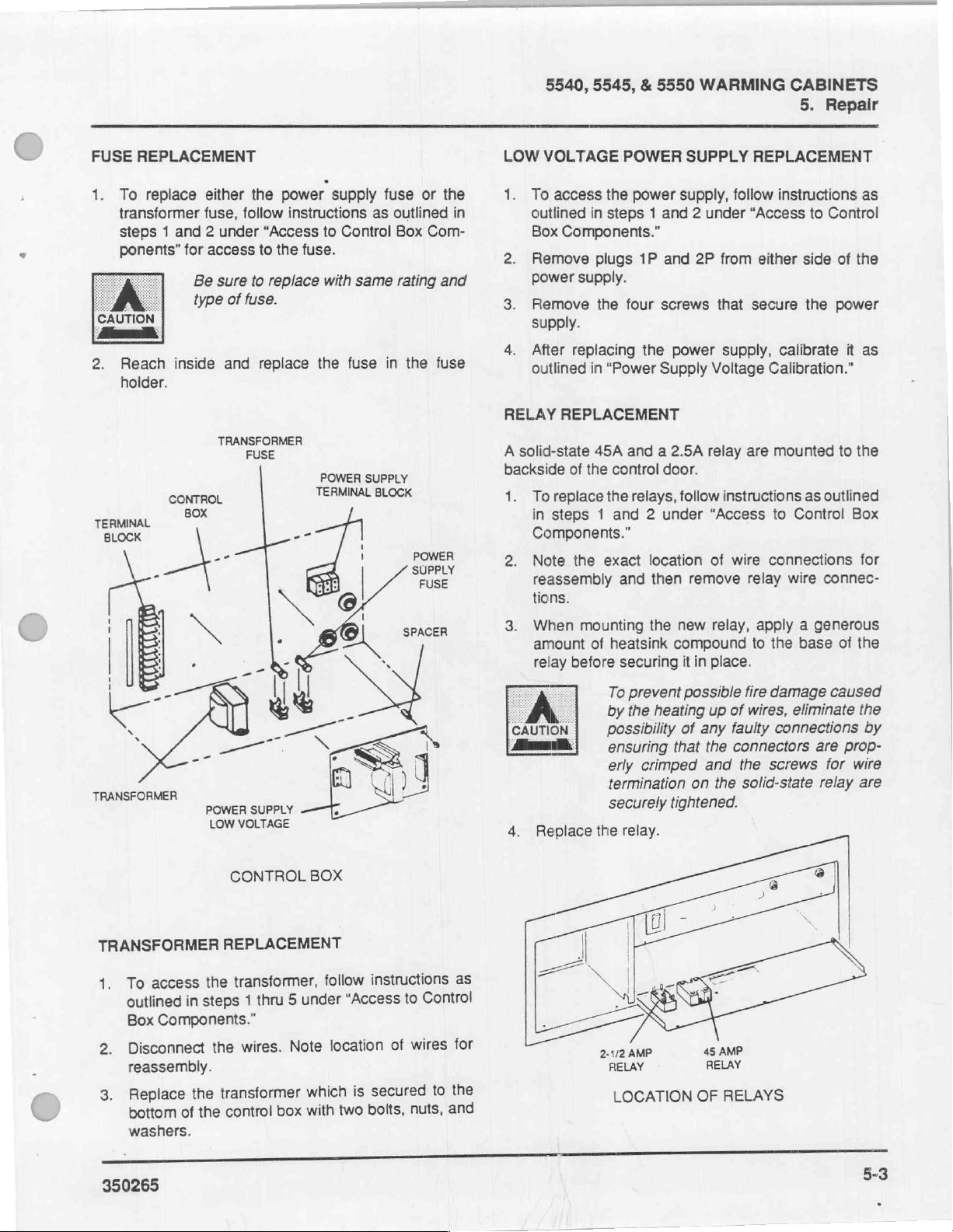
FUSE
REPLACEMENT
1.
To
replace
transformer
steps 1 and 2 under
ponents”
CAUTION
áno
2.
Reach
holder.
for
Be
type
inside
TERMINAL,
BLOCK
either
the
fuse,
follow
“Access
access
to
sure
to
replace
of
fuse.
and
replace
TRANSFORMER
FUSE
power
the
supply
instructions
to
Control
fuse.
with
the
POWER
TERMINAL
same
fuse
SUPPLY
fuse
as
outlined
Box
rating
in
BLOCK
the
or
Com-
and
fuse
the
in
5540,
LOW
VOLTAGE
U
To
access
outlined
Box
Components."
2.
Remove
power
3.
Remove
supply.
4.
After
outlined
RELAY
A
backside
US
REPLACEMENT
solid-state
To
replace
in
steps 1 and 2 under
Components.”
Note
reassembly
tions.
5545, & 5550
POWER
the
power
in
steps 1 and 2 under
plugs
1P
and
supply.
the
four
screws
replacing
in
45A
of
the
the
the
“Power
and a 2.5A
control
the
relays,
exact
and
Supply
door.
location
then
WARMING
SUPPLY
supply,
2P
power
Voltage
relay
follow
“Access
of
remove
CABINETS
5.
REPLACEMENT
follow
instructions
“Access
from
either
that
secure
supply,
instructions
wire
calibrate
Calibration.”
are
mounted
to
Control
connections
relay
wire
Repair
to
Control
side
of
the
power
to
as
outlined
connec-
the
it
the
Box
as
as
for
©
When
amount
CAUTION
Alim
TRANSFORMER
TRANSFORMER
fi
access
To
outlined
Components."
Box
Disconnect
reassembly.
Replace
bottom
washers.
in
the
of
POWER
LOW
the
steps
the
the
SUPPLY
VOLTAGE
CONTROL
REPLACEMENT
transformer,
5
thru
1
wires.
transformer
control
Note
box
BOX
follow
under
location
which
with
instructions
“Access
of
secured
is
bolts,
two
Control
to
wires
to
nuts,
as
for
the
and
4.
relay
before
A,
Replace
mounting
of
heatsink
securing
To
prevent
by
the
possibility
ensuring
erly
crimped
termination
securely
the
relay.
2-1/2
AMP
RELAY
LOCATION
the
new
compound
it
in
possible
heating
of
any
that
on
tightened.
OF
relay,
place.
up
of
faulty
the
connectors
and
the
the
solid-state
45
AMP
RELAY
RELAYS
apply a generous
to
the
base
of
fire
damage
wires,
caused
eliminate
connections
are
screws
for
relay
the
the
by
prop-
wire
are
350265
5-3
Page 37
5540, 5545, & 5550
5.
Repair
WARMING
CABINETS
HEATER
SOCKETS
=,
8
MOUNTING
BOLTS
FAN
=
TEMPERATURE
(To
Extend 1 8"
BEB
SENSOR
Below
<
STOP
Panel)
=
D
<=
5-4
CONTROL
BOX
COMPONENTS
350265
Page 38
FAN
REPLACEMENT
5540, 5545, & 5550
EPROM
REPLACEMENT
WARMING
CABINETS
5.
Repair
1.
To
replace
warming
“Access
Disconnect
Remove
secure
HEATER
1.
2.
3.
THERMOSTAT
1.
REPLACEMENT
To
replace
warming
“Access
Remove
three
screws.
Unscrew
place
in
To
replace
from
the
9
under
the
cabinet
to
Control
the
the
the
fan.
heaters,
cabinet
to
Control
the
the
heaters
the
exact
REPLACEMENT
the
warming
“Access
fan,
remove
as
outlined
Box
Components.”
fan
wiring.
four
bolts,
remove
as
outlined
Box
Components.”
heater
cover
from
location
thermostat,
cabinet
to
Control
the
control
in
steps 1 thru 9 under
nuts,
the
control
in
steps 1 thru 9 under
which
the
heater
from
remove
as
outlined
Box
box
and
washers
box
is
secured
sockets.
which
removed.
the
control
in
steps 1 thru
Components.”
from
from
the
that
the
with
Re-
box
©
上
Install
the
of
pin
1.
the
right
when
the
EPROM
To
avoid
EPROM
main
circuit
installing
EPROM
The
EPROM
and
align
EPROM
>
possible
or
PC
breaker
the
new
into
U12,
dot,
with
the
is
correctly
pekin
damage
board,
or
power
before
EPROM.
noting
notch,
notch
positioned.
ο
down
removing
the
orientation
should
on
socket
E
ecos
ğ
U12
to
point
U12
PIN
©
the
the
or
to
1
|
2.
Remove
three
screws.
3.
Remove
Remove
4.
offs,
with
TEMPERATURE
replace
To
1.
as
tions
Control
Loosen
2.
ature
sensor.
Disconnect
3.
the
heater
wires
from
thermostat
the
screws.
SENSOR
temperature
the
outlined
Components.”
Box
mounting
the
3-pin
the
in
the
steps
cover
bracket.
plug
which
thermostat.
which
REPLACEMENT
thru
1
from
is
secured
is
sensor,
under
5
Remove
the
secured
to
follow
“Access
the
control
with
stand-
instruc-
to
temper-
box.
SOCKET
EPROM
INSTALLATION
5-5
Page 39

5540,
5.
Repair
5545, & 5550
WARMING
CABINETS
PRINTED
To
È
2.
replace
outlined
Head
Disconnect
printed
reassembly.
3.
Refer
lockwashers
bly
to
4.
Separate
panel
a.
Disconnect
J2
b.
Remove
circuit
them.
CIRCUIT
in
Components.”
circuit
to
figure
the
as
follows:
connector.
BOARD
the
PC
steps 1 thru 3 under
ail
electrical
board.
below.
onthe
corners,
control
the
printed
the
board
head.
the
six
to
control
screws
the
REPLACEMENT
board,
circuit
plug
Note
Remove
that
bodrd
panel
that
control
follow
connections
location
instructions
“Access
of
the
four
screws
secure
from
ribbon
secure
panel
and
to
Control
from
plugs
the
assem-
the
control
cable
the
printed
separate
at
as
the
for
and
the
Reassemble
control
Exchange
ment
Installthe
ment.”
erly
as
Replace
connect
circuit
Adjust
.
Calibrate
“Calibrating
If
unit
11.
recorder
panel.
EPROM
circuit
board.
EPROM
Check
outlined
the
the
board.
the
volume
the
Temperature
is
equipped
as
outlined
the
replacement
from
as
outlined
that
the
jumpers
in
"Jumper
assembly
electrical
temperature
connections
as
outlined
with a recorder,
in
“Recorder
circuit
old
circuit
board
in
"EPROM
are
connected
Configuration.”
in
the
control
in
“Volume
control
Control.”
Calibration.”
board
to
replace-
Replace-
head
and
to
the
printed
Control.”
as
outlined
calibrate
to
the
prop-
re-
in
the
EPROM
—
区
B
7
scaew=——
=,
BRACKET
WASHER
PC
BOARD
REPLACEMENT
<
STANDOFF
CONTROL
PANEL
5-6
350265
Page 40

5540, 5545, & 5550
WARMING
CABINETS
‘5.
Repair
RECORDER
(Optional
a
To
replace
lined
Head
2.
Remove
corder.
3.
Remove
secure
leases
4.
Install
“Recorder
MOUNTING
SCREW
LOCKWASHER
&
REPLACEMENT
Equipment)
the
recorder,
in
steps 1 thru 3 under
Components.”
the
10-pin
the
four
the
recorder
the
recorder
new
recorder
Calibration.”
plug
securing
to
for
and
ED
follow
instructions
“Access
connection
screws
the
replacement.
calibrate
and
control
head
SS
to
from
washers
which
as
outlined
as
out-
Control
the
re-
that
re-
in
DOOR
τς
To
from
9
under
Remove
Press
the
the
DOOR
de
Replacement
a.
b.
Replacement
compartments
nets:
SWITCH
replace
the
panel,
panel.
GASKET
Raise
screws
(5540)/mounting
ket.
Assemble
mounting
door
the
warming
“Access
wires
the
clips
that
the
Remove
with
REPLACEMENT
door
cabinet
to
from
on
secures
REPLACEMENT
of
gasket
edge
that
the
the
strips
the
screws
of
gasket
on
switch,
Control
the
door
each
side
it
at
of
the
secure
strips
door
door
gasket
and
between
5545
and
remove
as
outlined
Box
switch.
of
and
remove
outer
gasket
(5545,
plate
then
that
were
5550
the
to
secure
the
control
in
steps 1 thru
Components.”
the
switch,
perimeter
to
5550)
or
mounting
the
removed.
upper
Warming
behind
forward
of
expose
door
and
door
plate
both
and
strips.
to
box
from
door:
the
plate
gas-
or
the
lower
Cabi-
nai
RECORDER
a.
Raise
screws
ket.
gasket.
b.
Assemble
then
that
the
that
Remove
secure
were
edge
of
secures
the
strip
the
gasket
both
removed.
to
the
both
of
to
the
gasket
the
strip
metal
the
strip
door
to
that
with
expose
and
the
secures
of
metal
the
the
gas-
the
and
screws
Page 41

5540,
5.
Repair
NOTES
5545,
&
5550
WARMING
CABINETS
350265
Page 42

5540, 5545,
&
5550
WARMING
CABINETS
Index
Index
A
Actual
Temperature
Adjustablo/Shelves!
Calibration
chaleco
ОЕ
power
ou
supply
ее
voltage
Preparatoria
termperalureicontto!
Citat
Condition
ControlPanel
Diagnostic
Diagnostic
Breaker
Indicator
Flow
Indicator
ET
Le
ee),
Charts
LED'S
Door
ДАО
IC
DoonAdiistnento
СВ
ao
suits
Display
πο
.
.
...........................
ο
ο
ο
σ
ντα
а
..............................
PS
.................................
TE
...............................
................,.............
о
i
A
ENT
al
ην
ο
A
SON
D
A
ο
νο.
E
Ls
O
MM
ο
A
dea
la
ee
Бы
q
a
1-4
eee
nam
e
1-4
4-3
4-3
4-2
era
IA
a
A
e
4-3
4-2
1-4
1-4
о
ан
1-4
3-2
1-7
a
O
a
es
O
AO
1-3
1-3
4-4
ENS
FMOD
Heated
ОЕ
AINRIOW
АВ
Heaters,.
Jumper
МАМ
Configuration.
РОО
do
o
r
ενω
"41,200,
o
o
αρ
so
(A
eee
ο
ma
ὦ
相
RO
e
F
H
ρα
J
le
M
yeme
τα
ni
ON
ime
e
и
o
неа
Een
US
an
주
1-4
1-3
1-5
3-10
1-4
1-6
1-4
350265
T
1-1
Page 43

5540,
Index
5545, & 5550
Overtemperature
Power
O)
ON
Recorder
Chart
Replacement
circuiibreakoM 2 2s
人
σοι
ΟΙ
EPROM!
TA
ОЭ
heater
lowivoltagelpower:suppliyi
ο
ες
MOCOrder
relay.
temperature
О
transformeri
WARMING
Switch
-
ose
ο.
sm
ое
amo
sun
ΓΣ
ο
fiw. < o
s9
sensor
CABINETS
0
..............................
P
o
o
ан
esa
o
e
ος ο woe e le
NN
о,
e.
. e
μμ
bono:
rw A Че
Zora e e
.........
ο
ο
ON
a
DR
a
мочь
μα
SME
le
ша
ia
ον
ER
А
wid
dee
EN
ος
e
овес
e v
0.el
AQU
an
OR
e
νο ο ο
O
ela
de
she
Rae
L
ею
e
I
one
SET
pal
ee
ala
elan | ©
PO
ый
сы
моечные
мк
LU
ls
a a
| в ров
le
le
ele a Gree
в
боюсь
ο
ο...
elm
mea.
e
sew
ee
ке о вы
ngi
OS
σος
n
a
mn el
whe
ules
e
의
e
а
a
ela
OL
ols
A
1-4
1-4
1-4
1-3
1-3
5-2
5-7
5-7
5-5
5-5
5-3
5-5
5-3
5-6
5-7
5-3
5-5
5-5
5-3
1-2
Sét-Point
Temperature
StorageiCompartment
Temperature
Teggle
Transformer = sc
Type'Configuration
Unit
Volume
Conversion
Switches = TO
sale
Control
Display: . lv.
a...
<2.
PUR
Chart
...........................
Salo
ce
站
ον
σα
OLO
5
SRE
Ti
sia
0
U
V
O
ONO
ο
e
he
inn
ο
CN
ees
de
e
e
ee e e
το
σσ»
개
1-4
1-3
1-5
1-7
1-4
1-6
1-7
350265
Page 44

f
NMN
M
fr
OPERATOR
Castle
WARMING
MANUAL
ノ
NY
5540
5545
5550
CABINETS
MDT
Biologic
1777
East
Henrietta
PO.
Box
23077
NL
Rochester,
New
York
jh
Technology
K
Company
Road
14692,
for
Life
U.S.A.
350264
ノ
>
ノ
Page 45
OPERATOR
MANUAL.
350264
(3/8/90)
Related
Installation
Service
Parts
Publications:
Instructions
Manual
Catalog
Special
using
safety
the
warming
DANGER
ως
τν
350263
350265
350266
signs
and
cabinet.
DESCRIPTION
The
following
"Danger"
could
be
notes
fatal.
instructions
It
is
are
the
responsibility
OF
symbols
alert
the
are
user
IMPORTANT
used
in
SYMBOLS
related
to
notes
the
possibility
this
of
&
manual.
the
user
NOTES
that
appear
of
Read
to
follow
IN
in
serious
them
carefully
all
recommendations.
MANUAL
this
manual.
personal
before
injury
which
CAUTION
мот}
"Warning"
"Caution"
"Notes"
notes
notes
alert
alert
alert
the
the
the
user
user
to
user
to
pertinent
to
the
the
possibility
possibility
facts
and
conditions.
of
personal
of
damage
injury.
to
equipment.
the
>
®MDT
and
Castle
are
registered
trademarks.
A
350264
Page 46

TABLE
OF
CONTENTS
€
SECTION
GENERAL. 0.00
DESCRIPTIONIOF
FieversibiesDoor
[πιο
Control
OptionalsRecorder
Main
iTouchiControt:
OPERATING
Tüuming
Selecting
Unloading;
Tuming
ο
Head
ds
Power
Switch/Circuit
INSTRUCTIONS
the
Wamming
the
o
thie
the
Warming
oca
de
a
COMPONENTS
A
RE
PSA
ο
Assembly
Panel
Set-Temperature
Cabinet...
Center
αμ
ντ
Cabinet
A
Cabine
Breaker
ες
.
ale
as
|
Storage
ο
ο
τος
On,
.....................................,....,...
2
Me
9
ei
E
CE
RSA
Compartment
ΙΣΗΣ
A
A
...........................................
ο
ouha
ol
ER
MERE
νο
αι ο νο ο εαν
RS
EE AA
ое
ар
e
mie
Te
CLS
ES
TS
PA
..............................
M
Το
A
le
TER
ое
vce
ας
неск
ο
A
rit)
RS
RTE
κκ
SC
бою
ое
A
en
NE
jp
aos
TRES
ло
2
ds
ое
оо
GL
i
NN
SiS
SS
men
ное
a
A
ο ο διὰ
σας
a
ke!
A ER E a a
sh
ohe
PAGE
le
ene
A
ii.
CURE
rue
ας
于
E
o
1
1
1
1
1
1
1
1
1
2
2
2
3
4
4
5
CONDITION
SHELF
RECORDER
PREVENTIVE
SPARE
OUALITY
和
ADJUSTMENT,
PARTS
ANDICATORS
A
CHART
MAINTENANCE!
REPLACEMENT
..................
SERVİCE - RELİABLE
A
:
AM,
PERFORMANCE
lulu
RS
a
cla
A
IA
e
eee
PT
LAINE
A
...............
led
es © Ay
RS
ee
tres
A
eee
alte
sen
eee
Бе
AYNEN
a
eee ene
as
lc
eels
ere
e
el,
o
이
EE
5
5
5
6
7
7
1-1
350264
t
iii
Page 47

The
special
before
safety
operating
instructions
the
warming
that
follow
cabinet,
IMPORTANT
appear
and
follow
within
the
the
manual.
instructions.
Read
them
carefully
"Danger"
Operating
Do
not
the
warming
agents
This
to
heat
Contact
cause
personal
surroundings.
Selecting
Unloading
Items
can
burn
may
temperatures
heat
temperatures,
items
items
burns
wear
removing
Unloading
When
internal
not
decrease
temperature
high
brought
temperatures
protect
wear
glassware
Instructions
relocate
may
unit
contains
and
with
explosion
injury,
the
The
heated
skin
come
in
items
to
from
the
with
an
to
skin
protective
hot
The
the
warming
temperature
temperature,
into
your
approved
from
notes
the
warming
cabinet
be
circulate
an
to
tissue.
contact
exceeding
temperatures
be
unprotected
tissue.
items
as
itself.
sudden
of
eyes
in,
any
introduced
electrical
air
within
airborne
or
fire
resulting
or
damage
"Warning"
Set-Temperature
Cabinet
temperatures
Do
with
49°C
careful
warming
gloves
Cabinet
rapidly
may
an
from
safety
the
when
cabinet.
To
or
from
the
cabinet
of
the
as
Some
react
contact
outside
possible
glasses
cabinet.
alert
the
cabinet
area
where
into
the
atmosphere.
components
the
cabinet.
flammable
in
serious
to
equipment
over
49°C
not
heat
any
bare
skin
(120°F).
in
excess
removing
Removing
hand
may
avoid
possible
use
tongs
warming
is
turned
cabinet's
the
internal
glassware,
violently
with
lower
environment.
shattering
when
user
to
to,
or
flammable
designed
agent
and
notes
(120°F)
item
to
If
you
of
49°C,
those
result
burns,
when
cabinet.
off,
the
contents
cabinet
if
heated
when
removing
the
page
operate
may
alert
the
page
page
that
do
hot
in
page
will
to
To
glass,
possibility
2
user
to
3
4
4
of
serious
Loading
Do
could
atmosphere.
components
within
flammable
resulting
equipment
the
Loading
Unloading
When
with
heated
skin.
when
warming
Condition
If a problem
items
minimum
temperature
would
damage
personnel.
Shelf
To
height,
hours)
them,
shelves.
Preventive
The
not
place
introduce
the
in
possibility
the
the
interior
compartments
Avoid
replenishing
cabinet.
is
necessary,
enable
to
Adjustment
prevent
either
for
or
wear
personal
Cabinet
items
flammable
This
designed
cabinet.
agent
may
serious
and
surroundings.
of
personal
The
Cabinet
The
Cabinet
warming
surface
contact
Indicators
occurs,
of
two
hours)
of
the
removal
the
items,
burns
to
allow
the
shelves
protective
Maintenance
injury
which
in
the
warming
agents
unit
contains
to
heat
Contact
cause
personal
injury.
cabinet
with
or
and
allow
items
the
sufficient
is
of
the
could
interior
removing
relocation
sufficient
for
the
to
without
or
resulting
skin
to
cool
gloves
could
cabinet
into
electrical
and
circulate
with
an
explosion
injury,
or
operating,
door
or
result
in
cabinet
items
of
time
internal
drop
to a level
causing
in
when
adjusting
time
(at
before
when
be
fatal.
page
which
the
cabinet
air
airborne
or
fire
damage
page
page
contact
any
of
burns
to
surfaces
in
the
page
heated
(a
which
possible
injury
to
page
least
two
handling
handling
page
4
to
4
4
the
the
5
shelf
hot
>
5
6
The
filter
possible
cool
before
surroundings
burns
to
skin
removing
may
by
the
be
hot.
allowing
filter.
Avoid
the
cabinet
350264
to
I
Page 48

5540,
5545
&
5550
WARMING
CABINET
RECORDER
(OPTIONAL
REVERSIBLE
DOOR
CENTER
(STORAGE)
COMPARTMENT
MODEL
(Cabinet
CENTER
(STORAGE)
COMPARTMENT
Model)
CONTROL
ASSEMBLY
5550
CONTROL
ASSEMBLY
HEAD
HEAD.
CONTROL
PANEL
DOOR
SWITCH
SHELF
FILTER
ADJUSTABLE
SHELVES
REVERSIBLE
RECORDER
(OPTIONAL)
DOOR
CENTER
(STORAGE)
COMPARTMENT
CONTROL
HEAD
ASSEMBLY
CONTROL
PANEL
MODEL
(Cabinet
5545
Model)
HEATED
DEFLECTOR
LOWER
UNHEATED
COMPARTMENT
AIR
RECORDER
(OPTIONAL)
REVERSIBLE
DOOR
FILTER
MODEL
(Cabinet
5540
Model)
CONTROL
PANEL
DOOR
SWITCH
all
DOOR
ACTUATED
SWITCH
+=
SIMS
OPTIONAL
TN
“8
RECORDER
vi
MODEL
(Recessed
5545 & 5550
Model)
MODEL
(Recessed
5540
Model)
350264
Page 49
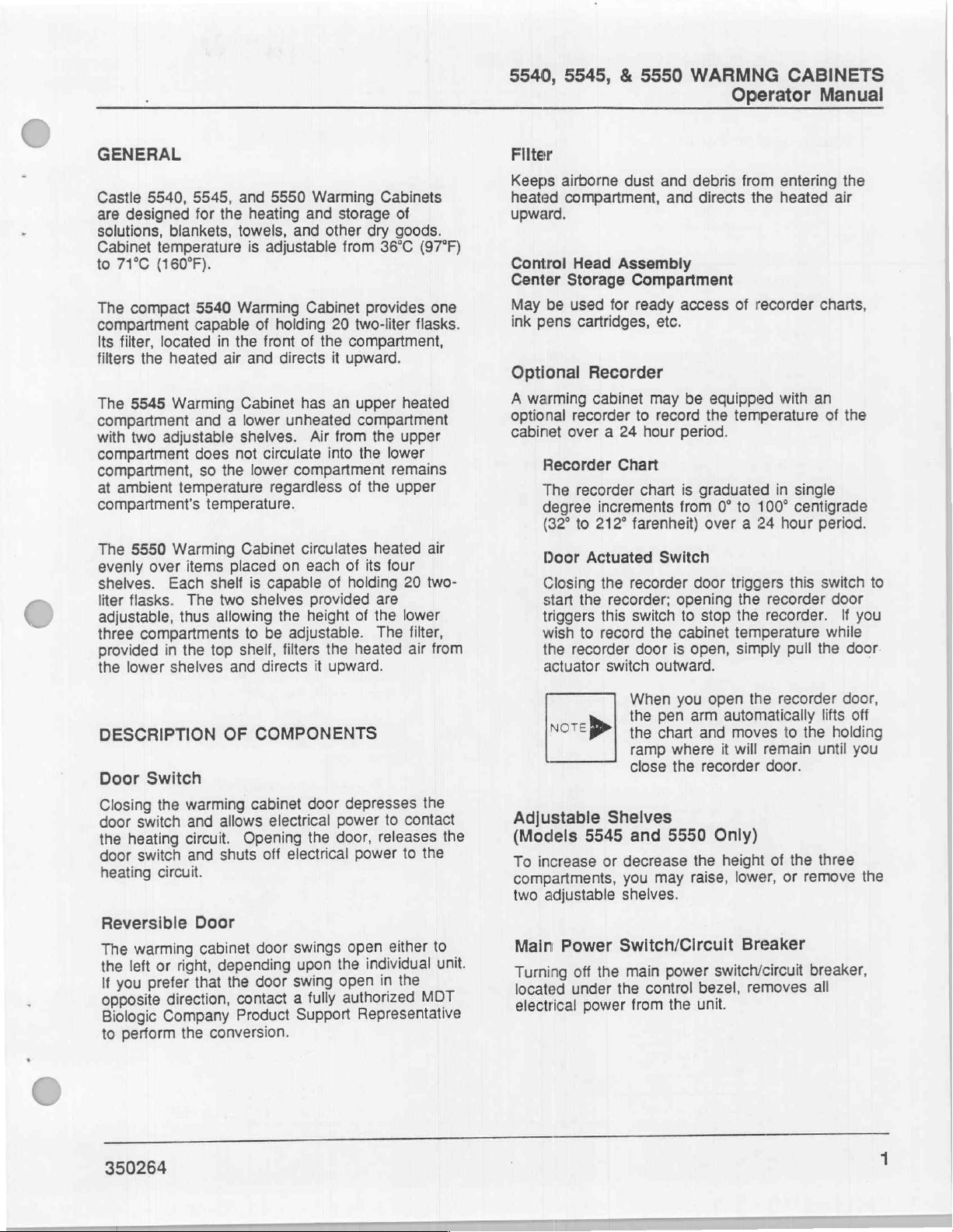
5540, 5545, & 5550
WARMNG
Operator
CABINETS
Manual
GENERAL
Castle
are
solutions,
Cabinet
to
The
compartment
Its
filters
The
compartment
with
compartment
compartment,
at
compartment's
The
evenly
shelves.
liter
adjustable,
three
provided
the
5540,
designed
blankets,
temperature
71°C
(160°F).
compact
filter,
located
the
heated
5545
two
adjustable
ambient
5550
over
Each
flasks.
compartments
in
lower
shelves
5545,
Warming
temperature
Warming
items
The
thus
the top
DESCRIPTION
Door
Switch
Closing
door
the
door
heating
the
switch
heating
switch
circuit.
warming
and
circuit.
and
and
5550
for
the
heating
towels,
is
adjustable
5540
Warming
capable
in
air
the
and
of
front
Cabinet
and a lower
shelves.
does
not
circulate
so
the
lower
regardless
temperature.
Cabinet
placed
shelf
is
capable
two
shelves
allowing
to
be
shelf,
and
directs
OF
COMPONENTS
cabinet
allows
electrical
Opening
off
shuts
Warming
and
storage
and
other
Cabinet
holding
directs
of
the
has
20
it
an
unheated
Air
from
into
compartment
circulates
on
each
of
provided
the
height
adjustable.
filters
the
it
upward.
door
power
the
door,
electrical
Cabinets
of
dry
goods.
from
36°C
(97°F)
provides
two-liter
flasks.
compartment,
upward.
upper
heated
compartment
the
upper
the
lower
remains
of
the
upper
heated
of
its
four
holding
20
are
of
the
lower
The
filter,
heated
depresses
air
to
contact
the
releases
the
power
to
one
air
two-
from
the
Filter
Keeps
heated
upward.
Control
Center
May
ink
Optional
A
optional
cabinet
airborne
compartment,
Storage
be
used
pens
warming
over a 24
Recorder
The
degree
(32°
Door
Closing
start
triggers
wish
the
actuator
NOTE
Head
cartridges,
Recorder
cabinet
recorder
recorder
increments
to
212°
Actuated
the
the
this
to
record
recorder
>
Adjustable
(Models
To
compartments,
two
5545 and
increase
or
adjustable
dust
and
and
Assembly
Compartment
for
ready
etc.
may
to
record
hour
Chart
chart
farenheit)
Switch
recorder
recorder;
switch
the
door
switch
outward.
When
the
pen
the
chart
ramp
close
Shelves
5550
decrease
you
may
shelves.
debris
directs
access
be
equipped
the
period.
is
graduated
from
over a 24
door
opening
to
stop
cabinet
is
open,
you
open
arm
and
where
the
recorder
Only)
the
raise,
from entering
the
heated
of
recorder
with
temperature
in
single
0°
to
100°
centigrade
hour
triggers
the
the
temperature
simply
recorder
recorder.
pull
the
recorder
this
automatically
moves
it
will
to
the
remain
door.
height
of
lower,
the
or
remove
the
air
charts,
an
of
the
period.
switch
door
If
you
while
the
door
door,
lifts
off
holding
until
you
three
to
the
Reversible
warming
The
or
left
the
prefer
you
If
opposite
Biologic
to
direction,
Company
perform
350264
Door
cabinet
right,
that
conversion.
the
door
depending
door
the
contact
Product
swings
the
upon
swing
fully
a
Support
either
open
individual
the
in
open
authorized
MOT
Representative
to
unit.
Main
Power
Turning
located
electrical
off
under
power
Switch/Circuit
the
main
power
the
control
from
the
Breaker
switch/circuit
bezel,
unit.
removes
breaker,
all
Page 50

5540,
5545, & 5550
Operator
Touch
Control
Power
Pressing
cabinet,
LED
Indicator
Pressing
"ON"
LED
Power
Pressing
cabinet,
allows
temperature.
Set-Temp.
Pressing
or
decrease
or
2°F)
from
36°C
Actual
While
hand
temperature
the
actual
cabinet.
Set-Point
; ; i ;
While
hand
temperature
the
temperature
cabinet
Condition
"OH"
display
cabinet
more
overheat
Manual
Panel
ON
this
button
and
activates
the
ON
button
OFF
this
button
de-activatates
the
cabinet
Up
and
these
buttons
the
cabinet
increments.
(97°F)
Temperature
the
control
temperature
Temperature
the
control
to
maintain.
appears
if
the
rises
than
condition.
to
panel
panel
you
Indicator
in
the
temperature
above
(7°F),
4°C
WARMING
turns
on
the
the
control
illuminates
turns
off
the
the
control
to
return
to
ambient
Down
71°C
display
display
the
Arrow
allows
Set-temperatures
Display
inside
you
temperature
(160°F).
is
activated,
continuously
the
Display
is
activated
continuously
selected
temperature
thus
for
of
the
set
temperature
alerting
CABINETS
warming
panel.
the
green
warming
panel,
Buttons
to
increase
in
1°C
range
the
indicates
warming
the
right-
indicates
the
warming
selected
warming
to
you
and
(1
left-
by
an
|
OPERATING
components
within
the
flammable
resulting
equipment
NOTE
Note
in
>
>
Turning
1.
Be
sure
já
located
2.
Turn
the
green
control
*
The
the
e
The
cabinet,
The
open.
operating,
and
INSTRUCTIONS
Do
not
relocate
to,
or
operate
any area
be
This
designed
cabinet.
agent
serious
and
To
warranty,
cabinet
Representative
required
electrical
If
the
an
hour
Refer
on
The
Warming
that
under
warming
ON
button
panel.
left-hand
current
unit
where
introduced
unit
contains
Contact
may
cause
personal
surroundings.
prevent
do
until
mechanical
tests.
warming
optional
recorder
to
“Recorder
page
5.
the
main
the
control
in
temperature
temperature
will
begin
providing
unit
will
not
If
you
open
the
remain
off
the
the
flammable
into
to
heat
with
explosion
injury,
voiding
not
an
MDT
has
cabinet
recorder,
chart
Cabinet
power
cabinet
the
lower
heating
that
begin
the
heating
until
you
warming
warming
the
atmosphere.
electrical
and
circulate
an
airborne
or
the
product
operate
the
Product
performed
adjustments
is
equipped
replace
on a daily
Chart
On
circuit
5
bezel
is
turned
on
by
pressing
left
corner
display
inside
the
door
the
heating
door
while
system
will
close
cabinet
cabinet
agents
or
damage
in,
may
air
fire
to
warming
Support
the
and
with
the
24
basis.
Replacement”
breaker
on.
the
of
the
will
show
the
cabinet.
inside
of
the
closed.
is
if
the
door
is
the
unit
is
shut
off
the
door.
ACTUAL
TEMPERATURE
CONTROLS
"ON"
SWITCH
CONTROLS
OFF”
SWITCH
2
一
一
能
>
二
1
=
o
=>
M
E
one
で
ニー
Re]
TEMPERATURE
SET
350264
Page 51
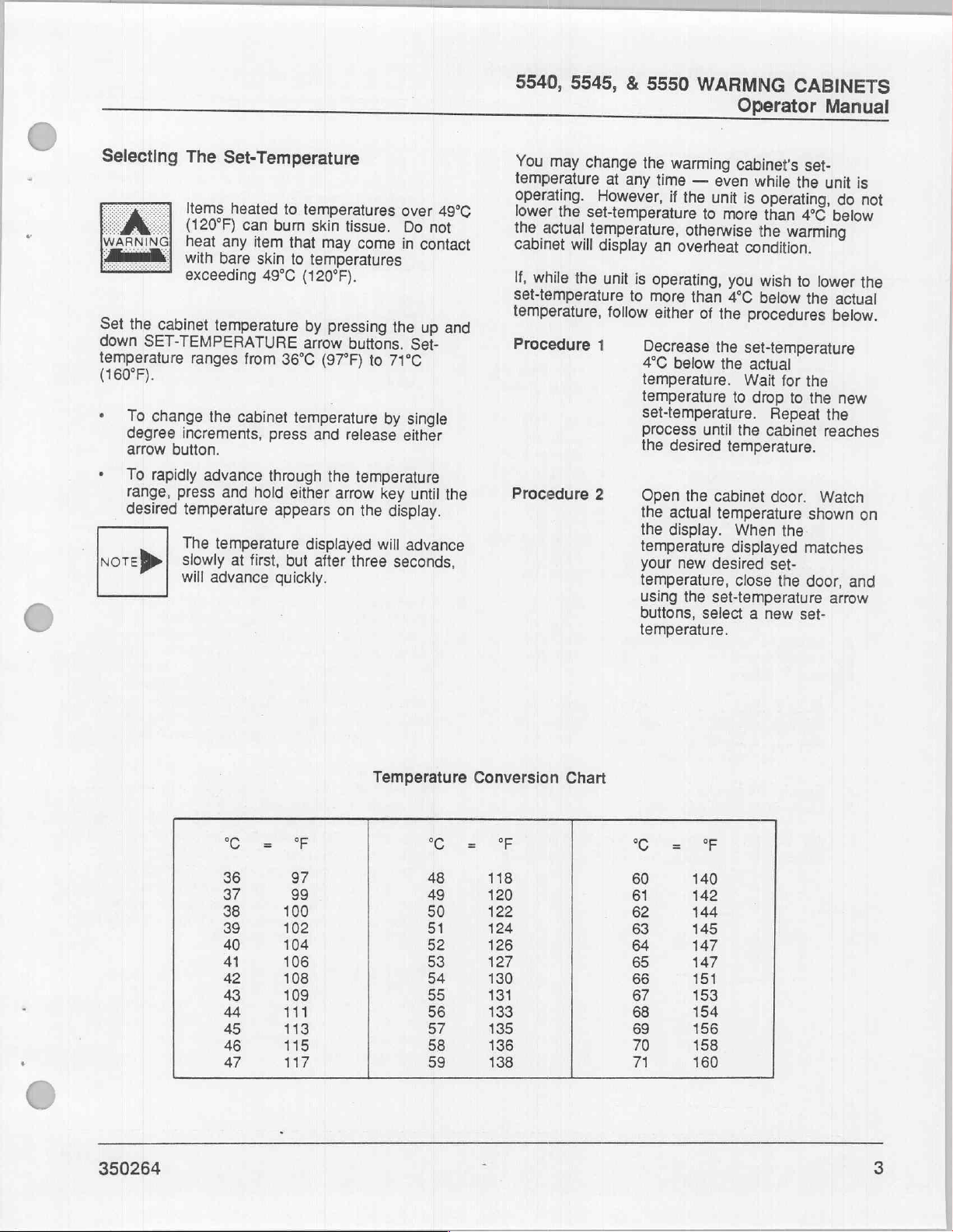
5540, 5545,
&
5550
WARMNG
Operator
CABINETS
Manual
Selecting
Set
down
temperature
(160°F).
・
:
the
cabinet
SET-TEMPERATURE
To
change
degree
arrow
button.
To
rapidly
range,
desired
νοτεβ»
The
Set-Temperature
Items
heated
(120°F)
heat
with
exceeding
ranges
increments,
press
temperature
The
slowly
will
can
any
item
bare
temperature
from
the
cabinet
advance
and
hold
temperature
at
first,
advance
to
burn
that
skin
to
49°C
36°C
temperature
press
through
either
appears
but
quickly.
temperatures
skin
tissue.
may
Pressing
buttons.
(97°F)
and
release
the
arrow
on
after
three
come
to
71°C
by
temperature
key
the
display.
will
temperatures
(120°F).
by
arrow
displayed
over
49°C
Do
not
in
contact
the
up
and
Set-
single
either
until
the
advance
seconds,
You
may
change
temperature
operating.
lower
the
the
actual
cabinet
If,
while
set-temperature
temperature,
Procedure
Procedure
at
However,
set-temperature
temperature,
will
display
the
unit
follow
1
2
the
warming
any
time
—
even
if
the
unit
to
more
otherwise
an
overheat
is
operating,
to
more
either
Decrease
4°C
below
temperature.
temperature
set-temperature.
Process
the
desired
Open
the
actual
the
display.
temperature
your
new
temperature,
using
buttons,
you
than
4°C
of
the
the
the
until
temperature.
the
cabinet
temperature
desired
the
set-temperature
select a new
temperature.
cabinet's
while
is
condition.
procedures
set-temperature
actual
Wait
to
drop
the
When
displayed
close
set-
the
operating,
than
4°C
the
warming
wish
to
below
the
for
the
to
the
Repeat
cabinet
door.
shown
the
matches
set-
the
door,
set-
unit
do
below
lower
actual
below.
new
the
reaches
Watch
and
arrow
is
not
the
on
350264
SCESE
36
37 99
38
39
40
41
42
43
44
45
46
47
97
100
102
104
106
108
109
1197
113
115
117
Temperature
C
48
49
50
51
52
53
54 130
55
56
57
58
59
Conversion
FSE
118
120
122
124
126
127
131
133
135
136
138
Chart
C
60
61
62
63
64
65
66
67
68
69
70
Wa
140
142
144
145
147
147
151
153
154
156
158
160
Page 52

5540,
5545,
Operator
&
5550
Manual
WARMING
CABINETS
Loading
bei
and
circulate
an
airborne
or
fire
resulting
damage
CAUTION
(Arme
Below
placing
warming
+
»
*
are
Always
shelves,
only
are
Storing
same
Do
exceeds
The
Do
e
cabinet
flammable
atmosphere.
electrical
air
flammable
to
the
When
contact
door
compartments
the
cabinet
removing
Do
section
be
|
withstand
some
solution
cabinet:
place
regardless
items
stored
dry
shelf
not
place
100
Cabinet
not
place items
which
agents
components
within
in
serious
equipment
the
warming
with
or
any
skin.
Avoid
surfaces
items
not
store
of
the
packaged
the
pointers
flasks
and
solutions
stored
with
in
dry
goods
is
and
acceptable.
items
Ibs.
onto
could
This
the
cabinet.
agent
personal
and
the
interior
of
the
could
contact
when
in
items
warming
in
material
selected
to
bear
dry
on
of
whether
the
cabinet
goods.
solution
whose
the
in
the
warming
introduce
into
the
cabinet
unit
contains
designed
Contact
may
cause
surroundings.
cabinet
heated
result
the
warming
in
the
temperature.
in
goods
the
upper-most
combined
adjustable
explosion
injury,
is
surface
in
burns
with
interior
replenishing
heated
cabinet
unable
mind
into
they
are
or
whether
flasks
weight
shelves.
to
heat
with
or
operating,
of
the
to
or
cabinet.
that
may
to
when
the
the
they
on
the
>
Always
iterns
permit
e
Position
they
*
Engure
cabinet
removing
6
temperature,
solutions
Unloading
When
from
following
When
internal
goods
cabinet
high
into
outside
possible
glasses
Items
can
may
temperatures
heat
temperatures,
items
items
to
skin
Protective
items
maintain a 2-inch
and
unobstructed
items
do
not
that
long
them
hours
the
temperature,
sudden
burn
come
items
for
The
unloading
warming
safety
the
warming
temperature
will
not
temperature.
contact
environment.
shattering
when
heated
skin
in
to
from
the
with
an
tissue.
gloves
from
the
the
ceiling
in
obstruct
items
enough
dry
and a minimum
to
reach
Cabinet
solution
points:
decrease
removing
to
temperatures
tissue.
contact
exceeding
temperatures
be
careful
warming
unprotected
To
or
warming
of
circulation
the
warming
the
are
stored
to
for
use.
goods
set-temperature.
flasks,
cabinet,
cabinet
of
heated
as
Some
may
react
with
lower
To
glass,
glassware
Do
with
49°C
when
cabinet.
avoid
possible
use
tongs
cabinet.
clearance
the
cabinet
of
heated
cabinet
circulation
in
the
heat
through
Allow a minimum
to
reach
the
of 8 hours
and
dry
bear
in
mind
is
turned
rapidly
glassware,
violently
protect
wear
over
not
heat
bare
(120°F).
in
excess
hand
off,
glassware
as
when
temperatures
your
approved
from
49°C
any
skin
to
removing
Removing
may
result
burns,
when
removing
between
chamber
so
of
air.
warming
before
set-
goods
the
the
and
the
internal
if
heated
eyes
safety
the
(120°F)
item
If
you
of
49°C,
those
in
wear
the
to
air.
that
of
for
dry
to
brought
of
an
from
cabinet.
that
do
hot
burns
hot
SÅ
When
with
the
heated
skin.
Avoid
when
removing
warming
the
warming
interior
compartments
cabinet.
surface
contact
or
cabinet
with
replenishing
of
the
could
interior
is
result
operating,
door
or
any
in
burns
cabinet
items
in
the
contact
of
the
to
the
surfaces
350264
Y
Page 53

5540, 5545,
&
5550
WARMNG
Operator
CABINETS
Manual
Turning
Turn
button
the
in
The
cabinet
the
CONDITION
An
overheat
temperature
the
selected
experiences
automatically
heating
temperature
you
of
press
the
Support
condition
of
temperature.
an
circuit,
display,
the
condition.
OFF
Personnel.
If a problem
heated
sufficient
hours)
the
would
possible
resulting
Warming
off
by
pressing
lower
left
corner
INDICATORS
occurs
the
cabinet
overheat
shut
down
display
button
items
the
and
If
and
items
time
for
the
to
enable
damage
in
injury
Cabinet
of
if
the
rises
If
the
condition,
the
electrical
letters
sound
this
condition
call
for
occurs
drop
and
is
necessary,
(a
minimum
internal
to a level
removal
to
the
to
personnel.
Off
the
red
the
control
interior
to
4°C
(7°F)
warming
the
unit
power
OH
in
the
an
alarm
ever
qualified
relocation
allow
of
temperature
which
without
items,
OFF
panel.
over
cabinet
will
to
the
alerting
arises,
Product
of
two
of
causing
or
1.
Lift
to
from
2.
Remove
squeezing
tilting
3.
Reassemble
on
on
shelf
RECORDER
1.
Open
automatically
holding
the
the
the
the
the
four
the
shelf
clips.
is
the
To
prevent
adjusting
sufficient
the
them,
handling
shelf
cabinet
the
the
clips
toward
CHART
recorder
ramp.
time
shelves
or
wear
hot
off
the
shelf
pilasters;
chamber.
clips
flanges
upward.
the
bracket
pilasters
Ensure
the
lift
off
burns
to
shelf
height,
(at
least
to
cool
protective
shelves.
four
bracket
remove
from
the
of
the
clips
place
and
that
the
front
of
REPLACEMENT
door.
the
The
chart
the
either
two
before
shelf
bracket
to
rolled
the
cabinet.
pen
and
skin
when
allow
hours)
handling
gloves
clips
attached
the
shelf
pilasters
clips
new
positions
shelf
the
edge
arm
move
for
when
by
while
back
of
will
to
its
the
1.
Wait
at
door
to
time
to
2.
Use
extreme
and
solutions;
of
the
overheat
3.
It
is
possible
condition
breaker
these
conditions
turned
pressing
condition
Product
problem
SHELF
You
compartments
the
two
off
ADJUSTMENT
may
change
shelves.
least
two
ensure
cool.
will
Support
and
that
care
items
condition
for a secondary
to
occur
be
shut
and
cannot
the
green
arises,
reset
the
by
adjusting
hours
before
the
unit
when
in
the
in
which
off
automatically.
the
display
be
"ON"
contact a fully
Representative
the
unit.
height
the
opening
has
removing
cabinet
may
be
overheat
the
panel
turned
button.
of
the
three
height
the
had
sufficient
glassware
at
the
extremely
main
AC
Under
will
be
back
on
If
this
authorized
to
address
lower
of
either
time
hot!
circuit
by
MDT
the
of
2.
Unscrew
3.
Remove
4.
Place
chart
edges
5.
Align
the
with
the
6.
Replace
7.
Shut
the
automatically
to
the
RED
PEN
TIME
INDEX
MARK
the
the
the
new
correct
time
the
recorder
chart.
T
ACTUATED
SWITCH
hub
used
chart
under
index
hub
move
|
1
DOOR
knob.
chart.
the
daily
mark
knob
door.
from
日
SN
over
two
time
and
CHART
GUIDE
the
guides.
line
on
the
tighten
The
pen
its
holding
hub and
on
the
recorder.
it
securely.
arm
ramp
|
—
slip
the
chart
will
back
HUBKNOB
С
350264
Page 54
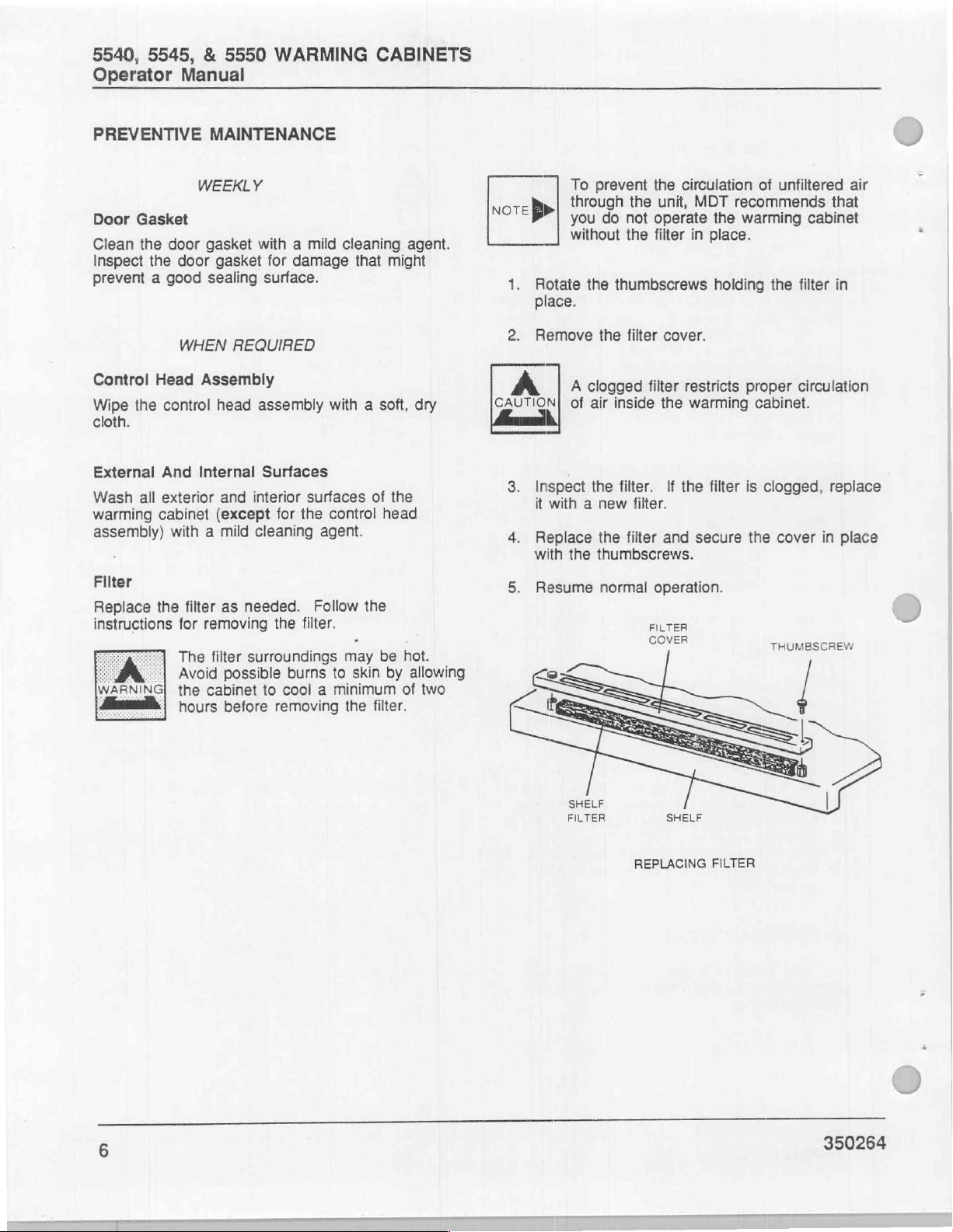
5540,
Operator
5545, & 5550
Manual
WARMING
CABINETS
PREVENTIVE
Door
Gasket
Clean
the
door
Inspect
prevent a good
Control
Wipe
cloth.
External
Wash
warming
assembly)
Fllter
Replace
instructions
WARNING
the
Head
the
control
And
all
exterior
cabinet
with a mild
the
door
for
The
Avoid
the
hours
MAINTENANCE
WEEKLY
gasket
gasket
sealing
WHEN
filter
REQUIRED
Assembly
head
Internal
and
(except
as
removing
filter
possible
cabinet
before
with a mild
for
damage
surface.
assembly
Surfaces
interior
cleaning
needed.
surroundings
surfaces
for
the
agent.
Follow
the
filter.
burns
to
cool a minimum
removing
cleaning
that
agent.
might
with a soft,
of
the
control
head
the
may
be
hot.
to
skin
by
allowing
of
the
filter.
dry
two
note»
1.
2.
CAUTION!
3.
4.
5.
To
through
you
without
Rotate
the
place.
Remove
A
clogged
of
Inspect
it
with a new
Replace
with
the
Resume
prevent
do
the
not
the
the
unit,
operate
filter
thumbscrews
the
filter
cover.
filter
air
inside
the
the
filter.
If
filter.
the
filter
and
thumbscrews.
normal
operation.
FILTER
COVER
circulation
MDT
in
place.
of
recommends
the
warming
holding
restricts
warming
the
secure
proper
filter
is
the
cabinet.
unfiltered
cabinet
the
filter
circulation
clogged,
cover
THUMBSCREW
air
that
in
replace
in
place
ーーー
ーーーーーr
6
SHELF
FILTER
SHELF
REPLACING
FILTER
J
350264
Page 55

5540, 5545,
&
5550
WARMNG
Operator
CABINETS
Manual
To
parts
or
ensure
listed
Part
69089
518404
69094
69095
69058
69037
69216
69195
518407
69107
530482
that
parts
below.
No.
are
immediately
Parts
with
SPARE
available
a
prefix
Part
Description
Relay,
Relay,
Fan,
Fan,
Door
Door
Shelf
Filter,
Temperature
Thermostat,
Temp.
solid
solid
120V,
230V,
Gasket,
Gasket,
Gasket,
clean
Recording
"+"
are
state
state
50/60
50/60
Model
Models
Models
air
probe
auto
PARTS
when
required
(2-1/2
(45
amp)
Hz,
127
Hz,
127
5540
5545
5545
assembly
reset,
Charts,
needed,
for
amp)
CFM
CFM
&
&
NO
24
routine
5550
5550
hr
(°C/°F)
maintain
a
maintenance.
Recommended
Quantity
1
1
2
2
1
1
1
1
1
1
1
box
stock
of
of
100
the
MDT
recommends
Support
symptoms
less
time
plan
offers
For
quality
plan,
contact
MDT
Biologic
telephone
To
ensure
spare
parts.
A
Service
Biologic
preventive
Representatives,
of
potential
consuming
scientific
service
your
Company,
area
code
that
parts
Manual
trouble
than
maintenance,
on
this
nearest
1777
716/475-1400.
are
and a Parts
Company.
QUALITY
RELIABLE
maintenance
using
authorized
and
making
repairing
equipment
MDT
immediately
damaged
not
Biologic
East
Henrietta
Catalog
SERVICE
PERFORMANCE
performed
parts
corrections
equipment.
merely
and
available
repair
information
Company
Road,
when
for
this
unit
—
by
and
service
immediately
service.
on
District
Rochester,
needed,
may
factory
trained
techniques.
is
Our
performance
our
performance
Service
Office;
New
maintain a stock
be
purchased
Product
Recognizing
less
costly
assurance
write
York
14692;
from
and
assurance
to
or
of
the
MDT
350264
0"
Page 56
5540,
Operator
5545, & 5550
Manual
WARMING
CABINETS
NOTES
8
350264
Page 57
5540, 5545,
&
5550
WARMING
CABINETS
Index
A
ACTUAL
ADYUSTABLE
TEMPERATURE
SHELVES
Be
CHARTDARECORDER
CIRCUIT
GENRONENİS
CONDITION
BREAKER)
kime
INDICATORS
GONMRONHEADASSEMBİY
GİNE
LZ
İN
Ee
RONETIOEES”
ο.
E
Set
Drying
SENO
Temperature;
erat
DISPLAY
...............................
..................................111.
B
C
e
oa
PER
ciel
ee
EEE
ele
e
ay
ο
ela
RSI
ον
e.
EL
Gus
e
e
i
ο
ecg
cee
LIU
ο
aaa
e
ο.
m
an
ro
ον
ου...
0
ln,
ο
ων
이
E
li
1,6
2
2,
5
2
2
2
2
1
1
1
1
1
5
350264
DANGER
SI.
DESCRIPTION,
DISPLAY
Actual
Set-Point
DOOR
DOOR
DOOR
EGOR
Temperaiie,
ACTUATED
(GASKET
SWITCH
REVERSIBLE
|
«cet.
mvt
Temperature
SWITOH
„.....
aja
ams
css
D
ое
n
Re
oli
.........,.,.........................
ce
ec ne
weil
ern
ss
caro
qui
ums
a
aaa
be
e
ele
еее
Oe
a
ee
el
üye
be
elmali
ela
вало
ne
0
ee
nee yen
aa
ео
ej
e
ond
a
Ш
ae
a
a
5
iv
1
2
2
1
6
1
1
11
—_
Page 58

5540, 5545, & 5550
Index
WARMING
CABINETS
E
EXTERNAL
EMER
GENERAL
INTERNAL
SURFAGES
e
e a ipa
ls
EE
SURRFACES
.
bezeme
.......
ilo
τα
νο
Ε
G
I
E
ος
allam
RE
ο
δν
hu
ο
κα
imes
το
jes
le
Vel
Ki a SE
da
oot
re
ae
1,6
a
6
1
6
12
EDİNDİ
LOADING
MRS
WARMING
MAINTENANCE
Control
DooriGasket
Externaliand/
RS
u
CABINET
LUS.
Head.Assermblý,
O
Internal
SUřaceS
RE
a
上
ACL
liti
し
SES
し
し
aa
し
M
に
ce
に
し
し
にし
e
に
に
Sr
al
CRE
トト
トゥ
に
に
・
に
に
に
トート
に
に
に
に
に
に
ale
e
ve
slam
geleli,
o
elena
he
e)
O
ee
O
ーーー
Es
V
tee
ee
ta
de
Rg
2
4
6
6
6
6
6
350264
Page 59

5540,
5545,
&
5550
WARMING
CABINETS
Index
e
e
i
ー
MODE
МОЕ
ВЕ
에
EL
OPERATINGINSTRUCTIONS
PERFORMANCE
ΕΛ
ΕΠΘΡΕ
ВОЕН
HOME
PREVENTIVE
ο
ВЕ
ONES
MO
он,
a
a
ASSURANCE
o
Иа
MAINTENANCE
M
Cont'd
ο
ο
ο
ος
ο
ο
o
e
..............................,
P
..................................
ee
RE
νο
,.
ια
ων
ων
RS
ων
LN
IS
Re
ων
ου...
op
ων
ο
κο
ων
e
o
O
ο
Mena
ων
a
ο
ik
ль.
νε
νο
enn
mi
ως
25
이
2,5
1
1
i!
2
2
7
2
1
6
350264
RECORDER
а
DOG
Ὦδοι
Replacementa
REPLACEMENT,
REVERSIBLE
e
ΡΜΠΟΙΓ
OPTIONAL
ντο
all
RECORDER
DOOR
а
ось
Бы
ii
ο
CHART
Β
Re
о
ово
το
ld
ο
...............,.....,.......
ое
νο
ен
бр
τον
ο
ο
о
as
ο...
ο
RISE
IO
ul
汪汪
οσα
의
1
i
5
1
5
5
1
1-3
Page 60

5540, 5545, & 5550
Index
ЗЕЕЕСТ
SERVICES
SETEPOINT
SHELF
SHELVES
SMUTEDOWNI
SPARE
STORAGE
SWITCH
ТЕМРЕНАТОНЕ
ADJUSTMENT
PARTS
DOON
ΜαΙΠΓΡΟΙΝΘΡ..
WARMING
о
TEMPERATURE
ER,
az
all
GOMPARTMENT
kulla
sa
Me
CABINETS
Sie
DISPLAN
LES
SR
-C
ser
toa
ANNE
ο
eno
MR
aloe
очен
EE
aft
humane e a
νο
ne
Зе
ls
$
фсе
ed
ο
N
ο
ВАН
be
혼비
ο
ок
Et.
τοσο.
cin
ae
ο
кое
ο μη
cease
μα
PR
AO
RO
ee © tle eae
ο
um
>
tells
CN
ο
ο
ее
Re
n
ме
il
ος
EEE
2,3
e O 7
wee
2
5
ne
1
и
5
e
7
BAİN
1
1
e
q
©
;
a
TEMPERATURE!
TOUCHICONTROLIPANELS
TURNING
TURNING
UNLOADING
WARMING
WARMING
WARMINGCABINET..............
WEEKEVIMAINTENANGE
CONS
.
.,
CABINET
CABINET
M
T
AIR
sakil
ee
esl
haf
ER
νε
ων
OFF
ON
εως
неа
.................,,...........
...............................
U
00
W
оон
ре
ea
ha
Şİ
ale
ον
ia
ρε
ь
58
2
5
2
4
6
5)
D
350264
Page 61

INSTALLATION
INSTRUCTIONS
Castle
5540
5545
5550
WARMING
Biologic
MDT
East
1777
PO.
Rochester,
CABINETS
Henrietta
23077
Box
York
New
Company
Road
*
14692,
U.S.A.
mom
Technology
for
Life
390263
2
Page 62

INSTALLATION
INSTRUCTIONS
350263
(3/2/90)
Related
Operator
Service
Parts
Publications:
Manual
Manual
Catalog
DESCRIPTION
The
A
SEAS
MD
350264
350265
350266
following
"Danger"
which
"Warning"
symbols
notes
could
notes
OF
alert
be
fatal.
SYMBOLS
are
related
the
alert
the
user
user
&
notes
to
the
to
NOTES
that
appear
possibility
the
possibility
IN
in
of
of
MANUAL
this
manual.
serious
personal
personal
injury.
ae
injury
CAUTION
NoTE
>
CAUTION]
"Caution"
"Notes"
notes
alert
the
Do
not
operate
Representative
performance
alert
the
user
the
makes
tests.
user
to
pertinent
warming
the
to
the
possibility
facts
cabinet
required.
and
conditions.
until
an
mechanical
of
damage
MDT
Product
adjustments
to
the
Support
equipment.
and
electrical
y
1
®MDT
ii
and
Castle
are
|
registered
trademarks.
350263
|
i
Page 63

TABLE
OF
CONTENTS
SECTION
ELECTRICAL
оо
О
MODEL
Positioning,
Electrical
MODEL
Positioning,
ElectricallGonnection
Cabin
MODELS
Positioning,
Electrical
MODEL
5545
Positioning,
ЕСО
Cabinet
REQUIREMENTS
ем
5540
RECESSED
Connection
CABINET
5540
Rss
5545
Connection
&
Leveling,
а
ООО
466600916
Leveling,
Leveling,
5550
&
Leveling,
5550
и
.......,.....,........................
т
and
Anchoring
...................................
and
A
"Ces
la
RECESSED
and
Anchoring
...........................................
CABINET
and
Anchoring
a
allame
ns
.
.................................
imame
EN
AN
...............,.................
.................................
asamada
seta
ea
nas
EU
ico
amo
sadia
cerne
aaa
・
「
емо
RE
PAGE
ον
UN
1
1
1
3
4
4
6
6
9
10
10
12
13
13
APPENDIX
APPENDIX
APPENDIX
APPENDIX
INDEX
A:
Roughing-In
B:
Roughing-In
C:
Equipment
D:
Equipment
la
for
Model
for
Models
Anchoring
Anchoring
5540
—
—
...........................
5545
&
5550
.....................
Seismic
Seismic
Forces
Forces
RD
for
for
xp,
à
Model
Models
5540.......
5545
EİN
&
5550
OS
A-2
A-4
A-6
A-7
1-1
350263
Page 64

Dimensions:
Uncrated
Weight:
Heat
Source:
Load
Capacity:
Model
2’6"
W
(762
W
180
Ibs.
Electric
20
two-liter
5540
x
29"
x
889
H
(82
flasks
x
2’?
D
H
x
610
kgs.)
TECHNICAL
D
mm)
5540,
5545,
DATA
Dimensions:
Uncrated
Weight:
Heat
Source:
Load
Capacity:
&
2'6"
(762
5550
WARMING
Installation
Models
Wx
6'2"H
W
x
1880
285
Ibs.
Electric
80
two-liter
5545
x
2'D
H
x
(192
flasks
CABINETS
Instructions
&
5550
610
D
mm)
kgs.)
“
Electrical
Supply:
ELECTRICAL
(By
Customer)
1.
Depending
either a 115V,
Phase,
Phase
2. A fused
electrical
cabinet.
3. A 1/2"
required
junction
diameter
routing
4.
Sufficient
required
junction
or a 230V,
electric
diameter
the
115V,
230V,
REQUIREMENTS
upon
the
50/60
supply
disconnect
supply
for
box
hole
space above
for
box.
line
electrical
connection
on
top
is
provided
conduit
access
50/60
50/60
voltage
Hz,
10
50/60
Hz, 5 Amp,
is
required.
switch
of
to
to
is
convenient
supply
to
the
the
unit. A 7/8"
in
the
junction
the
warming
the
electrical
Hz,
10
Amp,
Amp,
5
Hz.,
rating
of
Amp,
Single
required
to
the
line
electrical
the
top
panel
box.
cabinet
service
Single
Single
the
unit,
Single
in
the
warming
conduit
service
for
is
is
Phase
Phase
PERTINENT
ds
or
If
installing
temperature
exceed
The
5540
Models
fasteners,
with
the
9/32"
panel.
anchoring
fasteners
38°C
support
must
5545
seismic
warming
diameter
See
should
DATA
the
unit
in a recessed
of
the
recessed
(100°F).
structure
support
and
or
lag
anchoring
cabinet
holes
Appendices C and D for
drawings.
you
330
5550 - Using
fasteners
to
in
Minimum
be
2"
area
-
provide
Ibs.
(150
sufficient
requirements,
the
floor
through
the
base
length
(50mm).
area,
must
for
Model
kg.)
minimum.
1/4-20
to
anchor
of
each
seismic
of
the
not
lag
comply
two
side
lag
A
350263
a
Page 65
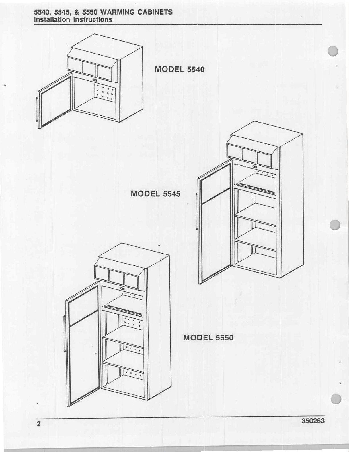
=
O
Q
山
글
10
19
<
©
RER
ВАА
==
|
Ja
\
MODEL
5550
Page 66

5540,
5545, 4 5550
Installation
WARMING
CABINETS
Instructions
SAVE
P
This
document
should
be
retained
contains
Do
not
introduced
atmosphere.
and
circulate
airborne
serious
useful
at
the
install
into
flammable
personal
FOR
information
warming
this
unit
the
atmosphere,
This
unit
air
from
injury
FUTURE
cabinet
in
contains
the
agent
or
REFERENCE
for
assembing
site.
any
area
where
or
may
electrical
surrounding
may
cause
damage
to
the
warming
flammable
be
introduced
components
atmosphere.
explosion
eguipment
or
agents
into
designed
Contact
fire,
resulting
and
surroundings.
cabinet
are
the
to
with an
and
heat
in
UNCRATING
CAUTION!
Move
1.
location.
Uncrate
2.
shipping
parts.
To
prevent
cabinet,
uncrating
while
warming
the
warming
the
to
bill
distortion
keep
the
moving
cabinet
ensure
the
door
and
unit,
it.
to
cabinet
you
that
of
the
closed
all
at
desired
the
check
and
received
warming
while
times
the
all
4.
installing
If
remove
area,
mounting
to
Refer
warming
the
studs
the
discard
and
attached
illustration.
cabinet
the
all
to
the
a
in
panel
side
recessed
panels.
Check
3.
ensure
supply.
cover
attached
illustration.
warming
the
matches
it
that
voltage
The
electrical
the
of
the
to
ELECTRICAL
cabinet’s
panel.
top
|
SERVICE
the
rating
service
JUNCTION
voltage
intended
appears
junction
to
Refer
to
rating
electrical
the
on
box
the
ELECTRICAL
SUPPLY
BOX
Сомов
ELECTRICAL
JUNCTION
BOX
LINE
MOUNTING
SIDE
PANEL
MOUNTING
STUDS
PANEL
PANEL
STUD
350263
3
Page 67

RECESSED
Installation
MODEL
MODEL
Instructions
5540
RECESSED:
5540
©
WARMING
CABINETS
POSITIONING,
AND
Refer
In
1.
ANCHORING
to
the
Roughing-In
Appendix
Note
For
>
California
Appendix
A.
dese
e
ва,
ноте»!
ве
supporting
Carefully
wall
slide
opening.
LEVELING,
seismic
anchoring
Administrative
C.
ll
рыть,
330
the
warming
Drawing
requirements
Code),
capable
ап
Ibs.
(150
kg.)
cabinet
(per
refer
to
anál
^^
of
minimum.
through
the
2.
Level
the
warming
the
floor
of
the
side
3.
Anchor
structure
the
side
panels
9/32"
panel.
as
the
warming
by
diameter
UNIT
DOOR
cabinet
unit
and
required.
inserting
holes
Refer
to
by
shimming
cabinet
two
the
to
lag
in
the
illustration.
SIDE
placing a level
under
the
the
support
fasteners
base
PANEL
through
of
each
LAG
FASTENERS
on
4
ANCHORING
THE
WARMING
CABINET
350263
Page 68
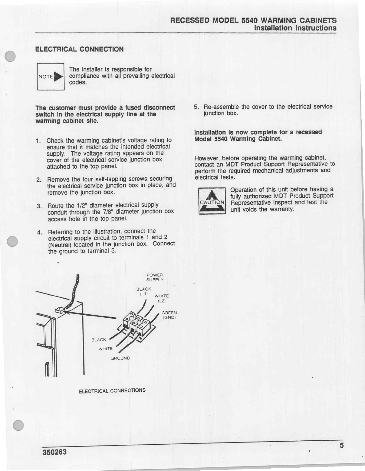
RECESSED
MODEL
5540
WARMING
Installation
CABINETS
Instructions
ELECTRICAL
note
>
customer
The
the
switch
warming
1.
2.
3.
in
cabinet
Check
ensure
supply.
cover
attached
Remove
the
remove
Route
conduit
the
of
electrical
the
access
CONNECTION
The
installer
compliance
codes.
must
electrical
site.
warming
that
it
matches
The
voltage
electrical
the
top
the
to
four
the
service
junction
the
diameter
1/2"
in
the
the
through
hole
is
responsible
with
all
prevailing
fused
provide
self-tapping
a
supply
cabinet’s
the
intended
rating
appears
service
panel.
junction
box.
line
voltage
junction
screws
box
electrical
diameter
7/8"
panel.
top
for
electrical
disconnect
the
at
rating
electrical
on
the
box
securing
place,
in
supply
junction
to
and
box
Re-assemble
5.
junction
Installation
Model
However,
contact
perform
electrical
5540
before
an
the
tests.
box.
MDT
CAUTION]
to
cover
the
is
now
complete
Warming
required
Operation
fully
Cabinet.
operating
Product
authorized
Support
mechanical
this
of
the
Representative
warranty.
the
voids
unit
electrical
the
for a recessed
warming
adjustments
unit
MDT
inspect
cabinet,
Representative
before
Product
and
service
and
having
Support
the
test
to
a
Referring
4.
electrical
(Neutral)
the
ーー
ground
o
illustration,
the
to
supply
located
to
terminal
ELECTRICAL
in
the
to
3.
CONNECTIONS
circuit
connect
terminals
junction
gi
box.
BLACK
(LT)
/
the
and
1
Connect
POWER
SUPPLY
write
(L2)
2
GREEN
(GND)
350263
;
5
Page 69
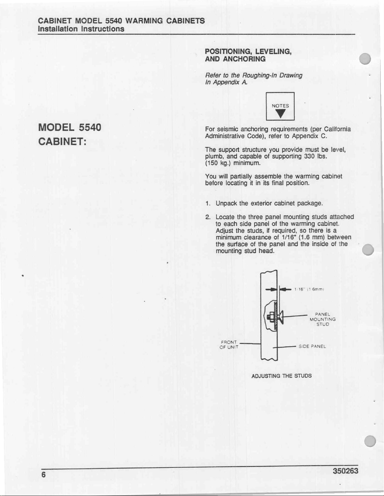
CABINET
Installation
MODEL
5540
Instructions
WARMING
CABINETS
MODEL
CABINET:
5540
POSITIONING,
AND
ANCHORING
Refer
to
the
Roughing-In
In
Appendix
For
seismic
Administrative
The
support
plumb,
(150
kg.)
You
will
before
1.
Unpack
2.
Locate
to
Adjust
minimum
the
mounting
A.
anchoring
structure
and
capable
minimum.
partially
locating
the
the
each
side
the
clearance
surface
stud
Code),
three
studs,
LEVELING,
NOTES
У
requirements
refer
you
of
supporting
assemble
it
in
its
final
exterior
panel
of
panel
if
the
panel
head.
cabinet
of
required,
of
Drawing
to
Appendix
provide
the
warming
position.
package.
mounting
the
warming
1/16"
(1.6
and
(per
must
330
Ibs.
studs
cabinet.
so
there
mm) between
the
inside
California
C.
be
level,
cabinet
attached
is
a
of
the
D
D
6
FRONT
OF
UNIT
ADJUSTING
THE
1:16”
SIDE
STUDS
(1
6mmi
PANEL
MOUNTING
STUD
PANEL
350263
Page 70

CABINET
MODEL
5540
WARMING
Installation
CABINETS
Instructions
NOTE
D>
3.
Assemble
mounting
long
provided,
mounting
warming
CABINET
SIDE
PANEL
The
cabinet
so
you
may
right
or
left
cabinet.
the
cabinet
studs.
self-tapping
fasten
brackets
cabinet.
screws
the
pra
side
assemble
side
side
Using
side
located
Refer
panels
of
the
panels
the
four
and
panels
on
to
the
=
are
identical,
either
one
warming
to
the
#10-24 x 3/8"
four
trim
washers
to
the
the
back
illustration.
Br
?—
n.
A
to
the
panel
of
the
#10-24 x 3/8
SELF-TAPPING
TRIM
WASHER
l
4.
Carefully
to
four
5.
Assemble
warming
long
washers
the
fastener
SCREW
MOUNTING
tip
assemble
feet.
the
cabinet
self
tapping
provided.
location
assembly.
PANEL
STUD
See
SA
the
the
of
|
|
warming
bottom
bottom
using
screws
Refer
the
designated
ioe
cover
cover
the
AT
cabinet
panel
panel
seven
and
seven
to
the
holes
SELF-TAPPING
TRIM
CABINET
SIDE
PANEL
onto
its
back
and
the
to
the
#10-24 x 3/8"
trim
illustration
for
#10-24 x 3/8
WASHER
for
the
SCREW
TRIM
#10-24 x 3/8
SELF-TAPPING
BOTTOM
_
COVER
WASHER
SCREW
PANEL
——
—
¿CON
WARMING
|
CABINET
ASSEMBLING
THE
SIDE
PANELS
WARMING
CABINET
350263
ASSEMBLING
BOTTOM
PANEL
ON
CABINET
Page 71
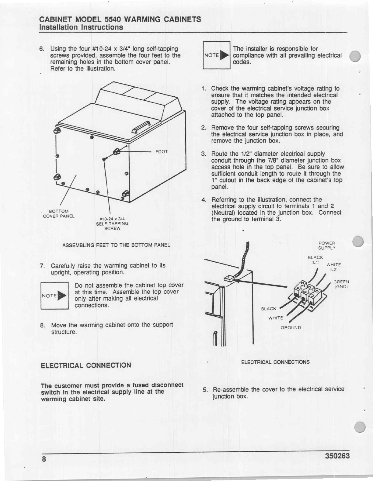
CABINET
Installation
6.
Using
screws
remaining
Refer
MODEL
Instructions
the
four
provided,
holes
to
the
5540
#10-24 x 3/4"
assemble
in
the
illustration.
WARMING
bottom
long
the
self-tapping
four
feet
cover
panel.
CABINETS
to
the
мот
>
1.
Check
ensure
supply.
cover
attached
2.
Remove
the
remove
3.
Route
conduit
access
sufficient
1"
cutout
panel.
The
installer
compliance
codes.
the
warming
that
it
The
of
the
electrical
to
the
the
four
electrical
the
junction
the
1/2"
through
hole
in
conduit
in
the
with
cabinet's
matches
voltage
top
panel.
self-tapping
service
diameter
the
7/8"
the
top
length
back
is
responsible
all
prevailing
the
intended
rating
appears
service
junction
box.
electrical
diameter
panel.
to
route
edge
of
for
voltage
electrical
on
junction
screws
box
in
place,
supply
junction
Be
sure
it
through
the
cabinet's
electrical
rating
to
the
box
securing
and
box
to
allow
the
top
i
BOTTOM
PE
ASSEMBLING
Carefully
7.
upright,
raise
operating
Do
Note
>
at
only
connections.
Move
the
warming
8.
structure.
ELECTRICAL
3/4
x
#10-24
SELF-TAPPING
SCREW
TO
FEET
warming
the
position.
assemble
not
this
time.
after
Assemble
making
cabinet
CONNECTION
BOTTOM
THE
cabinet
the
all
onto
PANEL
its
to
the
the
top
top
support
cabinet
electrical
cover
cover
4.
Referring
electrical
(Neutral)
the
(
,
ground
ㅣ
シン
to
the
supply
located
terminal
to
ZM
illustration,
circuit
in
the
connect
to
terminals 1 and
junction
3.
~
ώς
OSE
box.
BLACK
LV
the
Connect
POWER
roues
WHITE
2
č
na
GER
customer
Det
warming
8
the
in
cabinet
must
ar
site.
provide
a
supply
fused
at
line
disconnect
the
Re-assemble
5.
junction
box.
the
cover
to
electrical
the
-
i
service
350263
Page 72

CABINET
MODEL
5540
WARMING
Installation
CABINETS
Instructions
CABINET
In
order
to
structure
LEVELING,
but the
unit's
of
this
Using
screws,
panels.
electrical
the
SELF-TAPPING
(as
cabinet’s
installation,
top
the
assemble
Referring
supply
back
edge
#10-24 x 3/8
y
ASSEMBLY
move
the
instructed
AND
ANCHORING"),
top
all
panel.
six
#10-24 x 3/8"
the
to
conduit
of
the top
SCREW
|
warming
in
section
panel.
that
top
the
So,
remains
long
panel
illustration,
through
panel.
cabinet
to
"POSITIONING,
you
assembled
to
complete
is
the
installation
self-tapping
to
the
cabinet
route
the
1"
cutout
SUPPLY
its
support
all
the
side
the
on
ELECTRICAL
CONDUIT
CABINET
TOP
PANEL
WARMING
CABINET
LINE
Installation
5540
Warming
However,
contact
perform
electrical
CANTON
before
an
MDT
the
tests.
Operation
fully
Representative
voids
Is
now
complete
Cabinet.
operating
Product
required
authorized
the
for a cabinet
the
warming
Support
mechanical
of
this unit
MDT
inspect
warranty.
Model
cabinet,
Representative
adjustments
before
Product
and
having
Support
test
the
and
to
a
unit
ROUTING
ῇ
THE
ELECTRICAL
SUPPLY
CONDUIT
350263
Page 73
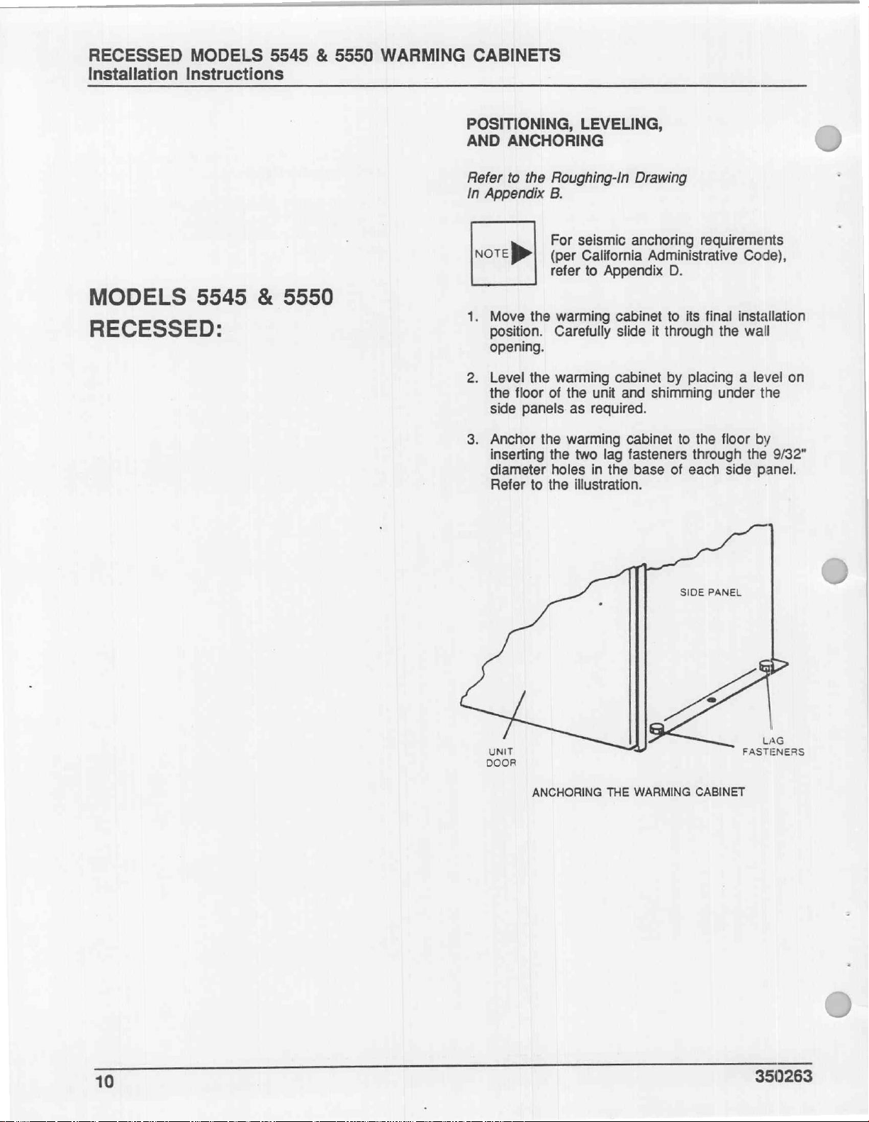
RECESSED
Installation
MODELS
Instructions
5545 & 5550
WARMING
CABINETS
MODELS
RECESSED:
5545
&
5550
POSITIONING,
AND
ANCHORING
Refer
to
the
Roughing-In
In
Appendix
Note
1.
Move
position.
opening.
2.
Level
the
side
3.
Anchor
inserting
diameter
Refer
>|
the
the
floor
panels
the
to
B.
For
(per
refer
warming
Carefully
warming
of
warming
the
holes
the
LEVELING,
Drawing
seismic
California
to
the
as
two
illustration.
anchoring
Administrative
Appendix
cabinet
slide
it
cabinet
unit
and
shimming
required.
cabinet
lag
fasteners
in
the
base
requirements
D.
to
its
final
through
by
of
the
placing a level
under
to
the
floor
through
each
side
Code),
installation
wall
on
the
by
the
9/32"
panel.
UNIT
DOOR
SIDE
#
ANCHORING
THE
WARMING
CABINET
PANEL
LAG
FASTENERS
10
350263
Page 74

ELECTRICAL
NOTE
De
The
switch
warming
1.
p
3.
customer
In
the
cabinet
Check
ensure
supply.
cover
attached
Remove
the
remove
Route
conduit
access
the
of
electrical
the
CONNECTION
The
installer
compliance
codes.
must
electrical
site.
warming
that
it
matches
The
voltage
the
electrical
to
the
top
the
four
service
the
junction
diameter
1/2"
in
the
the
through
hole
is
responsible
with
all
prevailing
provide a fused
supply
cabinet’s
rating
service
panel.
self-tapping
junction
box.
7/8"
top
line
voltage
the
intended
appears
junction
screws
box
electrical
diameter
panel.
RECESSED
for
electrical
disconnect
at
the
rating
electrical
on
the
box
securing
place,
in
supply
junction
and
box
to
MODELS
5.
Installation
Model
However,
contact
perform
electrical
CAUTIONS!
5545 & 5550
Re-assemble
junction
box.
Is
5545
or
before
an
MDT
the
required
tests.
Operation
fully
Representative
voids
Installation
the
cover
now
complete
5550
Warming
operating
Product
mechanical
of
authorized
the
warranty.
WARMING
to
the
for a recessed
Cabinet.
the
warming
Support
this
unit
MDT
inspect
CABINETS
Instructions
electrical
Representative
adjustments
before
Product
and
service
cabinet,
and
having
Support
the
test
to
a
unit
Referring
4.
electrical
(Neutral)
the
to
supply
located
ground
illustration,
the
circuit
the
in
terminal
to
ELECTRICAL
connect
terminals
to
junction
3.
GROUND
CONNECTIONS
box.
the
and
1
Connect
2
350263
11
Page 75

CABINET
Installation
MODELS
5545 & 5550
Instructions
WARMING
CABINETS
MODELS
CABINET:
5545
&
5550
POSITIONING,
AND
ANCHORING
Refer
to
the
Roughing-In
In
Appendix
B.
For
seismic
NoTE > (per
refer
1.
2.
3.
Move
the
position.
Level
the
the
floor
side
panels
Anchor
inserting
diameter
Refer
the
to
warming
warming
of
the
as
warming
the
holes
the
LEVELING,
Drawing
anchoring
California
to
Appendix
unit
required.
two
in
illustration.
Administrative
D.
cabinet
cabinet
and
shimming
cabinet
lag
fasteners
the
base
requirements
Code),
to
its
final
installation
by
placing a level
under
to
the
floor-by
through
of
each
side
the
the
9/32"
panel.
on
par
UNIT
DOOR
ANCHORING
THE
WARMING
SIDE
CABINET
PANEL
LAG
FASTENERS
12
350263
Page 76
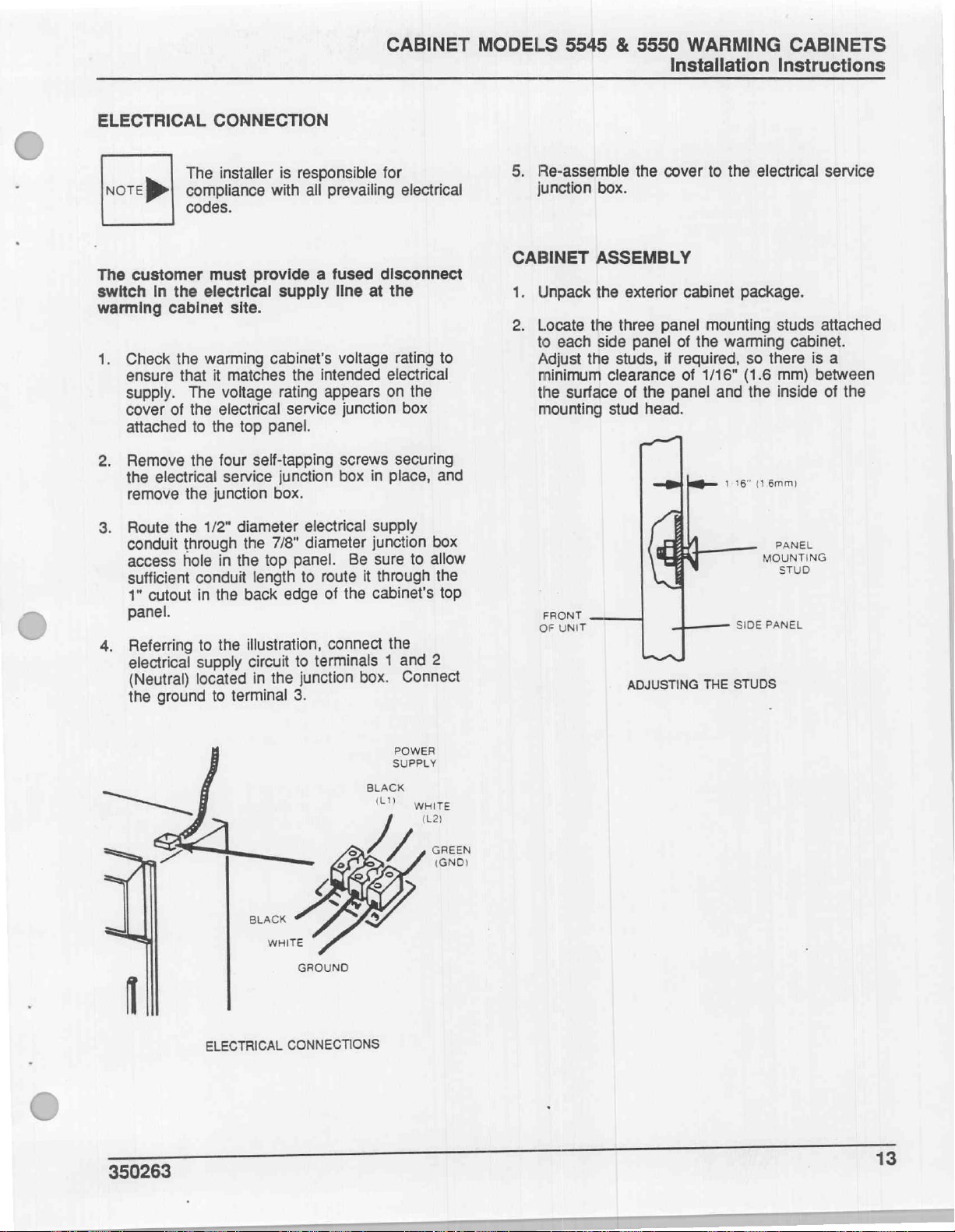
CABINET
MODELS
5545 & 5550
Installation
WARMING
CABINETS
Instructions
ELECTRICAL
Note}
The
switch
warming
1.
p
3.
4.
customer
In
the
cabinet
Check
ensure
supply.
cover
attached
Remove
the
remove
Route
conduit
access
sufficient
1"
panel.
Referring
electrical
the
the
of
electrical
the
cutout
(Neutral)
ground
CONNECTION
The
installer
compliance
codes.
must
electrical
site.
warming
that
it
matches
The
voltage
the
electrical
to
the
top
the
four
service
the
junction
1/2"
diameter
through
hole
conduit
located
in
the
the
in
to
the
supply
terminal
to
the
back
is
responsible
with
all
prevailing
provide a fused
supply
cabinet's
rating
service
the
line
voltage
intended
appears
junction
panel.
self-tapping
junction
screws
box
box.
electrical
7/8"
diameter
top
panel.
length
to
edge
illustration,
to
circuit
junction
the
in
Be
route
the
of
connect
terminals
3.
for
electrical
disconnect
at
the
rating
electrical
on
the
box
securing
in
place,
supply
junction
sure
to
it
through
cabinet's
the
and
1
Connect
box.
to
and
box
allow
the
top
2
Re-assemble
5
junction
CABINET
1.
Unpack
Locate
2.
to
each
Adjust
minimum
the
surface
mounting
FRONT
UNIT
OF
the
box.
ASSEMBLY
the
exterior
the
three
side
panel
the
studs,
clearance
of
the
stud
ADJUSTING
cover
panel
of
if
required,
panel
head.
to
the
cabinet
mounting
the
warming
of
1/16"
and
1:16“
THE
electrical
package.
studs
so
there
(1.6
mm)
the
inside
(1
6mm)
PANEL
MOUNTING
STUD
PANEL
SIDE
STUDS
service
attached
cabinet.
is
a
between
of
the
350263
ELECTRICAL
GROUND
CONNECTIONS
BLACK
(L1)
POWER
SUPPLY
WHITE
(L2)
13
Page 77

CABINET
Installation
3.
Assemble
the
panel
4.
Assemble
the
of
mounting
of
panel
the
shoulder
MODELS
the
5545 & 5550
Instructions
the
six
#10-24
brackets
warming
the
warming
mounting
screws.
attached
cabinet.
studs
PANEL
MOUNTING
STUD
shoulder
cabinet
and
SHOULDER
di
to
side
onto
#10-24
SCREW
WARMING
screws
the
rear
panels
the
heads
to
to
CABINETS
5.
Using
screws,
side
panels.
the
electrical
cutout
#10-24 x 3/8
SELF-TAPPING
the
six
assemble
at
the
SCREW
#10-24 x 3/8"
the
cabinet
Referring
supply
back
to
conduit
edge
the
of
long
self-tapping
top
panel
illustration,
through
the
top
the
panel.
to
the
route
1"
ELECTRICAL
SUPPLY
CONDUIT
CABINET
TOP
PANEL
WARMING
CABINET
»
LINE
WARMING
\
CABINET
ASSEMBLING
THE
SIDE
PANELS
ul
SIDE
PANEL
RIGHT
HAND
ROUTING
Installation
5545
or
However,
contact
perform
electrical
CAUTION
5550
before
an
MDT
the
tests.
is
required
THE
ELECTRICAL
now
complete
Warming
operating
Product
Operation
fully
authorized
Representative
unit
voids
Cabinet.
the
Support
mechanical
of
this
the
warranty.
SUPPLY
for a cabinet
warming
unit
MDT
inspect
CONDUIT
Representative
adjustments
before
Product
and
Model
cabinet,
and
having
Support
test
the
to
a
350263
Page 78

APPENDICES
APPENDIX
Appendix
Appendix
Appendix
Appendix
A:
B:
C:
D:
Model
Models
Model
Models
5540
5545
5540
5545
Roughing-In
&
5550
Equipment
&
5550
Roughing-In
Anchoring
Equipment
Drawing
Drawing
-
Seismic
Anchoring
Forces
-
Seismic
Forces
350263
A-1
Page 79

APPENDIX
For
APPENDIX
Roughing-In
greater
DOOR
CLEARANCE
DOOR
CLEARANCE
detail,
DOOR
SWING
È
LEFT
DOOR
e
SWING
aims
RIGHT
DOOR
|
>
A:
refer
2-6”
SWING
CLEARANCE
=
HAND
SWING
HAND
SWING,
テン
Model
Drawing
to
Drawing
7
ンジ
5540
#HS5019.
11-178"
=
SEE
SEE
av
NOTE
8
FINISHED
CHAMBER
FLOOR
—
\
\
FREE-STANDING
e
22"
OPENING
VIEW:
FRONT
(CABINET)
14.3
CHAMBER
172%
OPENING
VAZ
BEZEL
SWING
CLEARANCE
ARAN
e
farsa,
Ka
e
|
Ri
VIEW:
VIEW:
var
SIDE
PLAN
—
9/32"
DIA.
FOR
LAG
(SEE
NOTE
SUPPLIED
OTHERS
HOLE
FASTENER
7)
8Y
\
350263
Page 80
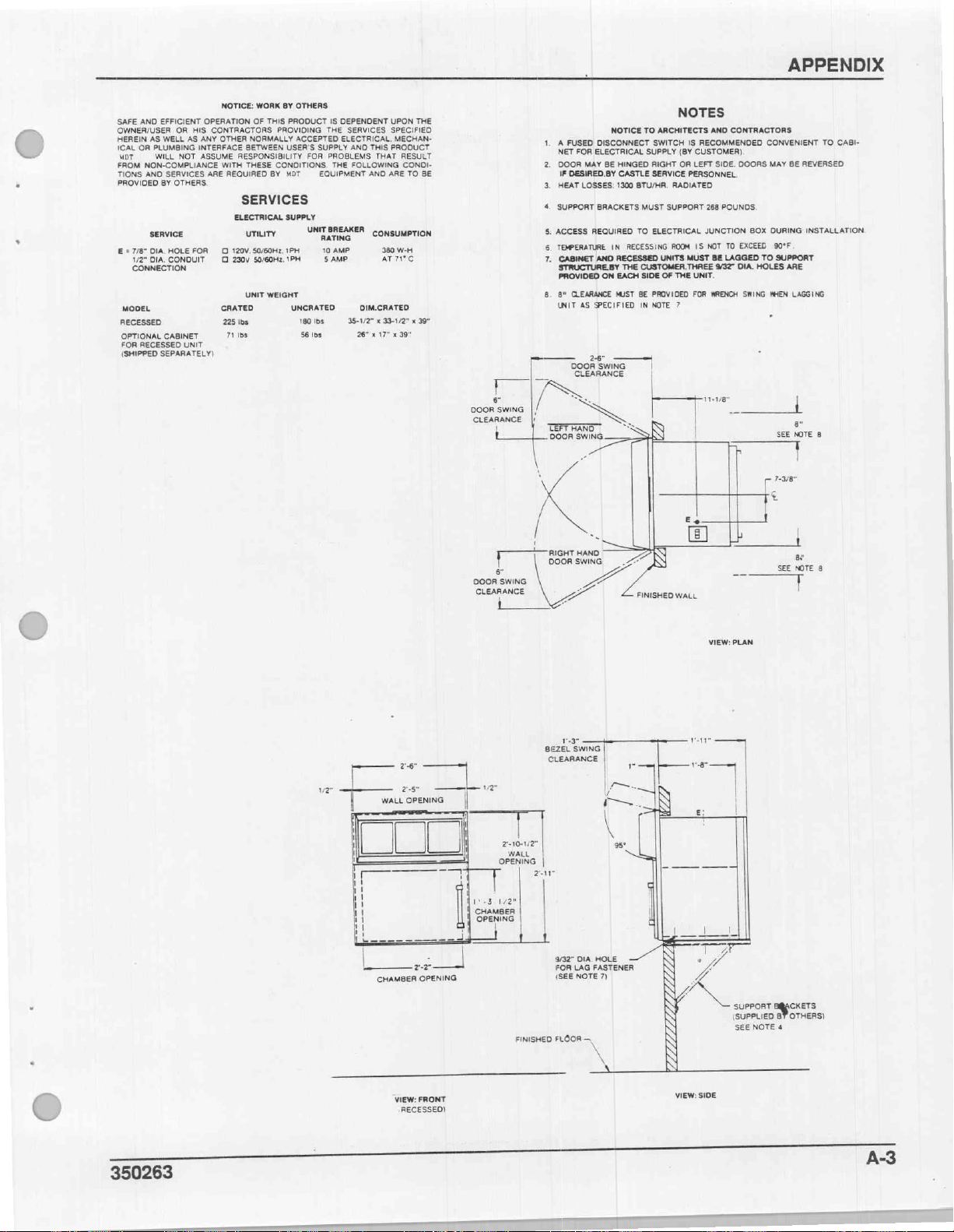
APPENDIX
NOTICE:
WORK
BY
OTHERS
SAFE
AND
EFFICIENT
OWNER/USER
HEREIN
AS
ICAL
OR
PLUMBING
MDT
WILL
FROM
NON-COMPLIANCE
TIONS
5
i
AND
PROVIDED
SERVICE
E = 7/8"
DIA.
1/2"
DIA.
CONNECTION
MODEL
RECESSED
OPTIONAL
FOR
RECESSED
(SHIPPED
OPERATION
OR
HIS
WELL
AS
ANY
INTERFACE
NOT
ASSUME
SERVICES
BY
OTHERS.
HOLE
FOR O 120V.50/60Hz,
CONDUIT Q 2304
CABINET
UNIT
SEPARATELY)
OF
CONTRACTORS
OTHER
NORMALLY
BETWEEN
RESPONSIBILITY
WITH
THESE CONDITIONS.
ARE
REQUIRED
SERVICES
ELECTRICAL
UTILITY
S0/60Hz,
UNIT
CRATED
225
lbs
71
Ibs
THIS
PRODUCT
PROVIDING
ACCEPTED
USER'S
BY
MDT
SUPPLY
1PH
1PH 5 AMP
WEIGHT
UNCRATED
180
56
IS
THE
SUPPLY
FOR
PROBLEMS
THE
EQUIPMENT
UNIT
BREAKER
RATING
10
AMP
Ibs
lbs
DEPENDENT
ELECTRICAL.
UPON
SERVICES
ANO
FOLLOWING
DIM.CRATED
35-1/2" x 33-1/2" x 39"
26" x 17" x 39"
THE
SPECIFIED
MECHAN-
THIS
PRODUCT
THAT
RESULT
CONDI-
AND
ARE
TO
CONSUMPTION
380
W-H
ATIC
BE
s
SWING
DOOR
CLEARANCE
1. A FUSED
NET
2.
DOOR
IF
HEAT
“
>
SUPPORT
5.
ACCESS
TEMPERATURE
o
7.
CABINET
STRUCTURE.BY
PROVIDED
8.
8"
UNIT
TEFTHAND
DOOR
NOTICE
DISCONNECT
FOR
ELECTRICAL
MAY
BE
DESIRED.BY
LOSSES:
BRACKETS
REQUIRED
IN
AND
RECESSED
ON
CLEARANCE
MUST
AS
SPECIFIED
2-6"
DOOR
SWING
CLEARANCE
>
>
SWING
HINGED
CASTLE
1300
RECESSING
THE
EACH
à
-
\
/
ae
DOOR
SWING
CLEARANCE
|
RIGHT
HAND
DOOR
SWING
M
NOTES
TO
ARCHITECTS
SWITCH
IS
SUPPLY
RIGHT
SERVICE
BTU/HR.
MUST
TO
CUSTOMER.THREE
SIDE
BE
PROVIDED
IN
NOTE
|
RECOMMENDED
(BY
CUSTOMER)
OR
LEFT
PERSONNEL.
RADIATED
SUPPORT
ELECTRICAL
ROOM
|S
UNITS
MUST
OF
THE
UNIT.
FOR
7
Hire
N
FINISHED
WALL
AND
CONTRACTORS
SIDE.
DOORS
268
POUNDS.
JUNCTION
NOT
TO
EXCEED
BE
LAGGED
9/37"
DIA.
WRENCH
_
T
BOX
TO
HOLES
SWING
CONVENIENT
MAY
BE
REVERSED
DURING
INSTALLATION
90°F
SUPPORT
ARE
NHEN
LAGGING
|
-
8
SEE
NOTE
]
ra
çö
£
-
8
TO
CAGI-
O
vz“
—
ーーーーー
ーー
Lad
26"
r
5
WALL
OPENING
CHAMBER
VIEW:
RECESSED)
Li
OPENING
FRONT
var
1.3
CHAMBER
OPENING
210-102"
WALL
OPENING
ae
1/2“
FINISHED
13"
BEZEL
SWING
CLEARANCE
|
|
|
3/32"
DIA
FOR
LAG
(SEE
NOTE
FLOOR
NV
VIEW:
PLAN
var
ice
Li
95°
HOLE
FASTENER
7)
\
A:
VIEW:
SIDE
|
—
SUPPORT
(SUPPLIED
SEE
NOTE
CKETS
OTHERS)
8
4
350263
A-3
Page 81

APPENDIX
TT
a
DOOR
SWING
CLEARANCE
1
T
В
boz
CLEARANCE
NE
‘
|/
LEFT
\
i
[N
T
Sen
2-6"
DOOR
SWING
CLEARANCE
>
KS
HAND
R
SWING.
7
Sane
^
APPENDIX
For
greater
à
トーー
>
a
P
ニー
Es.
|
|
パト
イ
me
ーー
—
つ
7-3/8"
=
B:
Models
Roughing-In
detail,
SEE
€
1
ar
NOTE
T
refer
7
+
8"
SEE
NOTE
7
Drawing
to
L=
DOOR
PORRO
!
”
DOOR
SWING
CLEARANCE
5545
Drawing
ING
|,
LEFT
DOOR
a,
RIGHT
DOOR
&
5550
#HS5018.
2-6"
DOOR
SWING
CLEARANCE
HAND
SWING
HAND
SWING
s
ンク
È
A
=
_22
24
FINISHED
E
WALL
LE
一
=
=
h
r
7-3/8"
ς
E
i
E
ENTE
+
|
8"
SEE
NOTE
T
A
7
FINISMED
FLOOR
E
Mİ
uz
\
VIEW:
PLAN
(CABINET)
WALL
|
ls
ea
|
i
1
|
1
1
1
1
=
ㅣ
|
|
1
|
|
|
1
Е
|
CHAMBER
VIEW:FRONT
26
——|
2-5"
OPENING
=
2-27
OPENING
Le
1/2"
T
|
|
sue
WALL
OPENING
1
|
|
|
i
내
|
し
と
BEZEL
CLEARANCE
6-2"
var
SWING
48-12”
CHAMBER
OPENING
TS
f=
NN
№
+
=
SS
pr
一
|
vm
해
ει
pee
一
VIEW:
VIEW:
PLAN
(RECESSED)
-
|
ae
그
1
I
1
|
|
|
1
1
1
I
1
1
1
1
|
!
!
|
A
一
一
一
/
SIDE
—
1/4°-20
LAG
BOLT
SEE
NOTE
4
A-4
350263
Page 82
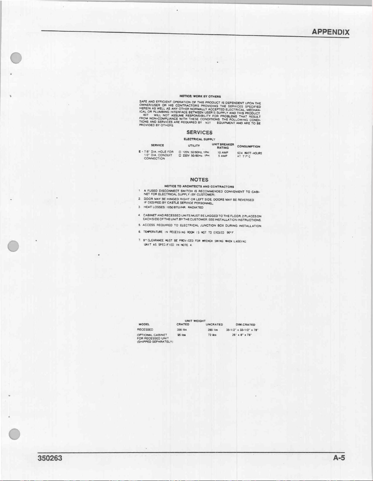
APPENDIX
NOTICE:
WORK
BY
SAFE
ANO
OWNER/USER
HEREIN
AS
ICAL
OR
PLUMBING
MOT
WILL
FROM
NON-COMPLIANCE
TIONS
AND
PROVIDED
SERVICE
E
=
7/8"
DIA.
1/2"
DIA.
CONNECTION
1
A
FUSED
NET
FOR
2.
DOOR
MAY
DESIRED
IF
3.
HEAT
LOSSES:
4.
CABINET
EACH
SIDE
ο a
ACCESS
TEMPERATURE
8“
CLEARANCE
UNIT
AS
EFFICIENT
OR
HIS
WELL
AS
ANY
INTERFACE
NOT
ASSUME
SERVICES
OTHERS.
BY
HOLE
FOR
CONDUIT
NOTICE
DISCONNECT
ELECTRICAL
BE
HINGED
CASTLE
BY
1850
AND
RECESSED
OF
THE
UNIT.BY
REQUIRED
IN
RECESSING
MUST
SPECIFIED
OPERATION
CONTRACTORS
OTHER
BETWEEN
RESPONSIBILITY
WITH
THESE
ARE
REQUIRED
SERVICES
ELECTRICAL
UTILITY
0
120V.S0/60Hz.1PH
O
230V
TO
ARCHITECTS
SWITCH
SUPPLY
RIGHT
SERVICE
BTU/HR.
RADIATED
UNITS
THE
TO
ELECTRICAL
ROOM
BE
PROVICED
IN
NOTE
OTHERS
OF
THIS
PRODUCT
PROVIDING
NORMALLY
ACCEPTED
USER'S
FOR
CONDITIONS.
BY
MDT
SUPPLY
UNIT
SO/E0HZ.1PH
NOTES
AND
CONTRACTORS.
IS
RECOMMENDED
(BY
CUSTOMER)
OR
LEFT
SIDE.
BE
LAGGED
JUNCTION
IS
NOT
WRENCH
DOORS
SEE
TO
EXCEED
PERSONNEL.
MUST
CUSTOMER.
FOR
4
IS
DEPENDENT
THE
SERVICES
ELECTRICAL.
SUPPLY
AND
THIS
PROBLEMS
THE
FOLLOWING
EQUIPMENT
RATING
10
INSTALLATION
BOX
SWING
BREAKER
«|
AMP.
SAMP
CONVENIENT
MAY
TO
THE
FLOOR.
DURING
90°F
ΜΗΕΝ
AND
CONSUMPTION
604
AT
BE
LAGGING
UPON
THE
SPECIFIED
MECHAN-
PRODUCT
THAT
RESULT
CONDI-
ARE
TO
BE
WATT-HOURS
71°C
TO
CABI-
REVERSED
2
PLACESON
INSTRUCTIONS,
INSTALLATION.
350263
MODEL
RECESSED
OPTIONAL
FOR
RECESSED
(SHIPPED
CABINET
UNIT
SEPARATELY)
UNIT
RATED
356
Ibs
95
Ibs
WEIGHT
UNCRATED
285
158 = 35-1/2% x 39-1/2" x 78"
72
bs
DIM.CRATED
26° x 6" x 78"
A-5
Page 83

APPENDIX
¢
b
ーーー イ ーー
i
i
ls
a
A
W aj
FRONT
+
κ
у
27"
ELEVATION
Equipment
For
トー
|
ey
greater
coG.wT.=
180
1
|
APPENDIX
Anchoring
detail,
LBS.
TABLE
USE
(WITH
TOP
(<
4-1/4" @ BOLTS
DOUBLE
C:
refer
NUT)
Model
—
Seismic
to
Drawing
5540
Forces
#530487.
2
+
だ
CG.
"
+
+
BASE
PLAN
AT
+
+
|
=
LOADS:
BOLT
PER
WEIGHT
HORIZONTAL
VERTICAL
FORCES:
TENSION
SHEAR
NOTES:
PROVIDE
SUPPORT
ENGINEER
(BY
CALIFORNIA
(W) = 180
ACCELERATION
(T)
T - -
(V)
v
TABLE
WEIGHTS
OF
CODE
LBS.
ACCELERATION
180º - 277,
4
81*
=
STRUCTURE
RECORD
AND
=
23
FORCES
FOR
Tra = 8
Vem = 27
REGULATIONS,
OF
(Vy)
(Vy)
=
0.15W
=
UBS/BOLT
LBS/BOLT
0.45W
=
TITLE
80
=
27
LBS
(8121850) . 4
218")
LBS/BOLT(TAX)
DESIGNED
SHOWN.
THE
TO
BUILDING).
23P.
LBS
24,
TABLE
LBS/BOLT(MAX)
A-6
350263
Page 84
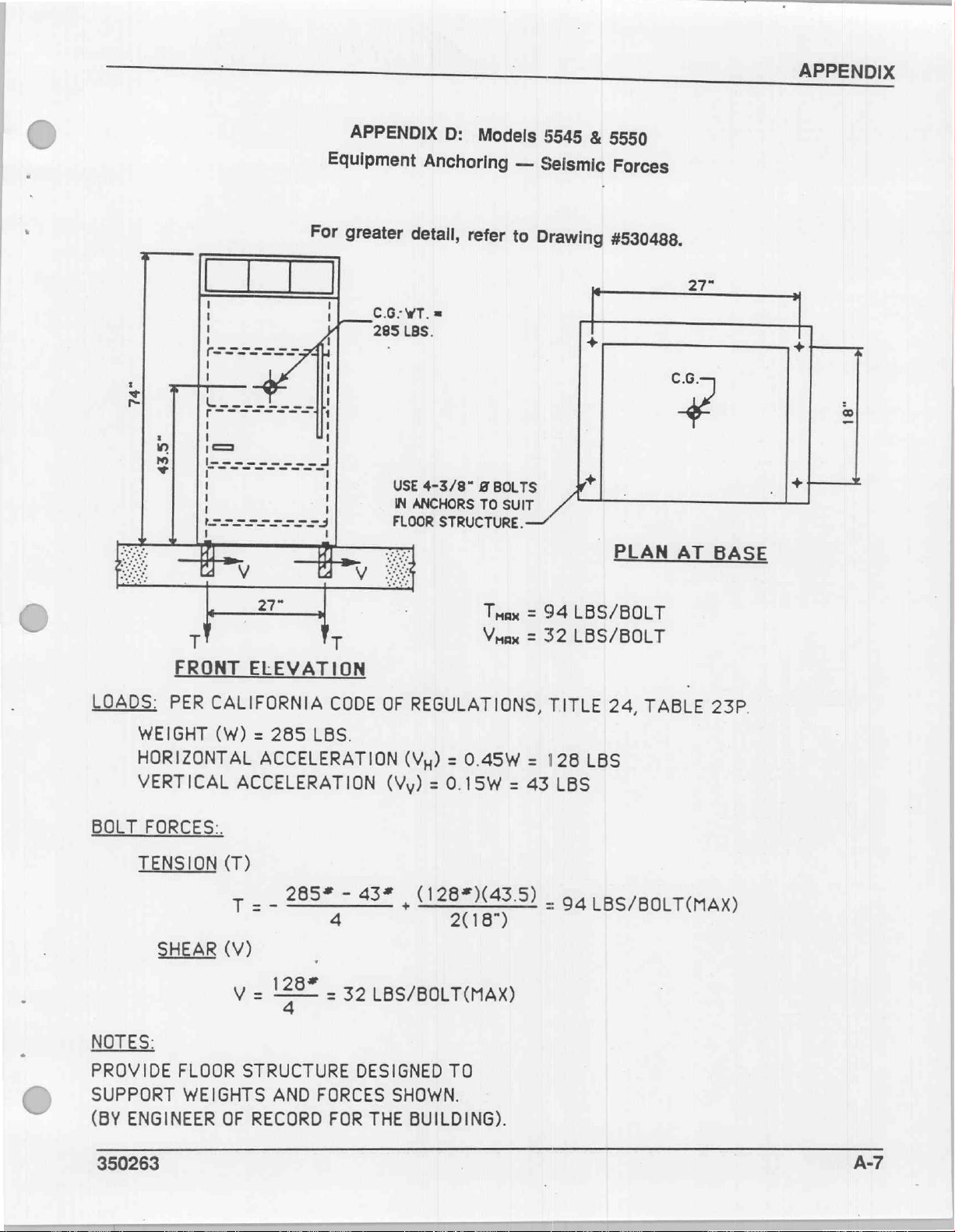
APPENDIX
é
©
a
|
さ
in
R
ay
一
27"
т
APPENDIX
Equipment
For
greater
=
D
T
CG:wT.
285
USE
IN
FLOOR
도
D:
Anchoring
detail,
LBS.
ANCHORS
-
refer
=
4-3/8“
STRUCTURE.
Models
—
Seismic
to
Drawing
gBOLTS
TO
SUIT
—
Tuax
=
Vax
=
5545
&
I
αἱ
94
LBS/BOLT
32
LBS/BOLT
5550
Forces
#530488.
|
PLAN
27"
6.6.
+
AT
BASE
T
he
©
C
LOADS:
WEIGHT
HORIZONTAL
VERTICAL
TENSION
SHEAR
NOTES:
PROVIDE
SUPPORT
(BY
ENGINEER
FRONT
PER
CALIFORNIA
(W) = 285
FLOOR
WEIGHTS
ELEVATION
LBS.
ACCELERATION
ACCELERATION
(T)
T
=
-
285%
(V)
yiz
STRUCTURE
OF
RECORD
|
τος = 32
AND
FORCES
CODE
4
-
43%,
OF
REGULATIONS,
(Vy)
=
(Vy)
=
0.15W
(128*)(43.5)
2(18")
LBS/BOLT(MAX)
DESIGNED
FOR
THE
SHOWN.
TO
BUILDING).
0.45W
=
TITLE
=
128
43
.
24,
TABLE
LBS
LBS
94
LBS/BOLT(MAX)
23P.
350263
A-7
AA
Page 85

Page 86

INDEX
A
O
(AE
CABINET
CABINET
DIMENSIONS
B
e
A
©
ASSEMBLY
ο
A
e
o
ο
RE
ο
o
ο
e
A
ο
D
σ
аа
II
πμ,
E
A
m
ld
e
IN
l
osa
RU
io
m
LE
Ds
e
4,
e
FE
ㅣ
ei
6,
10,
A-2
A-4
A-6
A-7
用
12
6
12
9
18
1
ELECTRICAL
ASIS
SUD
ELECTRICAL
MedellS540)
Model'S540)
Models
Models
HEATESOURGE
CONNECTION
Cabinet
Recessed,
5545
&5550Cabinet
5545
8
이.
5550
CREO
li
ER
Recessed
E
O
..........................
.................................................
H
ιο
ST
1.0.0
e
E
or
2000
TDI
人
ln
1
1
8
5
18
11
1
350263
1-1
Page 87
INDEX
EOADICAPACHTV
MODEL
MODELISSADICABINEN.
MODEL
ΜΟΡΕΙ 5 5545 ἃ 5550
5540
ROUGE
GdhbjetAssembly
Electrical
Positioning,
5540)RECESSED.
EEIG6tIGGIIGGRRGGHORI
Posttioning;
Roughing-ni.
SGISMIGVAMCHOHNG)
erin
IR.
a
COMMECIÓN:
Laveling,
Leveling;
.. . .
OURS
IE
0.00.
..0.
and
and!
. .
(ce
Horn
boe
ANCROMNG
ο
ESESS
Anchoring)
이
1
esis
3
ste
em
SRE
ο
aale
ο
eo
«ck
ео
7.
οσο
ο
>
0101
ος
alee
lak
оны
ο
το
M
de + hw
A
MS
se
ое
στ
e
оно
L
ebano
Rao
бо
ео
cl
а
στ
ое
ορ
ra
se eb
зы | vo
пере
να
N
аа
оз
ew
qu
ο
ο
AO
e
NE
ea
tata
lo] o La a oa
ja
qa
ce
бое
о
ο.
AS
A
еее
RO
toa
a
e
Ce
e
a
oo
a
ie
ER
os
lle
lees
LATE
ise
ο...
ee
а
q
19
A-2
A-6
6
9
8
6
4
5
4
A-4
A-7
MODELS
MODELS:5545
PERTINENT
POSITIONING,
5545/8
ElectricaliCOnnegtionmi
Positioning,
Elsctricali
Positioning,
Model
5540
Model
Models
Models
SS50ICABINET
Leveling,
5550/RECESSED....
&
Connection
Leveling,
ВРАТА
LEVELING,
Cabinet
Recessed
5540
&
5545
&
5545
e
5550
5550
ear
O
ол
ユー
ντο
lala
eleme
ое
レー
ドレ
ez
|...
e
cite
1.0.
Anchoring
and
=.
Anchoring
and
as
AND
に
11
上
.............,.1.,.,.4...
Cabinet
Recessed
+
.............................................
22
.
1...
.............................................
бо
ANCHORING
に
に
に
に
1
に
1
に
1
..................................................
.................................................
ekin
ドド
に
e
e
バト
eve
ae
ele
e
SW)
preço
RT
o
P
ое
トト
トト
トッ
ドー
Tale
e
О
トト
ドド
に
va
e
トト
af
ce
ise
Фа
ai
рен
©
トト
トド
トト
に
a
ağ
een
o
トド
ドド
に
e)
トト
e
に
ドレ
al
e
on
al
トド
6
OO"
ceo
ое
トド
ピード"
e
od
ドッ
e
5
ee
ae
ale
Da
ele
coco
トド
a
トード
ETES
are
Vea
GE
e)
fe
e
이그
기
"で
12
13
12
10
11
10
1
6
4
12
10
I-2
350263
Page 88
RECESSED
IModelN5540
МОЧЕ:
ROUGHING-IN
о
Models
SEISMIC
TECENICAL
ANCHORING
A
πω ο ο
5545155550...
SI
οσο
A
A
DATA
SO
μμ
μμ
νο
ο
ея:
ο
ο
nan
νο
Ül
ei
A
R
gele
S
IEA
T
llene
A
elele
RO
ne
AE
ous
See e eee
crv
ee
NL
çi
ei
ae
wile
ege
a
ek
a
DS
SOLS
ee
lenen
emiş
Em
аз
Belle
ike
INDEX
abi 4
İS > 10
A-2
le
Α-4
A-6
ne
A-7
На
1
UNCRATING
(^
Εαν
ne
dm
ed
e
ο
U
W
ο
ο
ο
nee
ec
σος
ο
ο
ο.
πο
NES
3
1
350263
1-3
Page 89

PARTS
Castle
3541, 3641,
EO
5540,
WARMING
GAS
5545,
CATALOG
&
4241
AERATOR
&
5550
CABINET
ノ
à
MDT
Biologic
ochester,
New
Company
Yor!
MOT
Technology
i
for
UO.
A.
Life
350270
ji
X
2
Page 90

PARTS
CATALOG
For
Product
may
350270
ordering
Support
contact:
(5/24/90)
information
Representative
concerning
or
MDT
Rochester,
ORDERING
parts
listed
your
nearest
Biologic
P.O.
Box
New
(716)
475-1400
in
this
MDT
Company
23077
York
Catalog
Regional
14692
contact
Office.
your
Or,
MDT
you
note
>
©
MDT
and
Castle
are
registered
All
parts
intact
Rochester,
trademarks.
replaced
to
MDT
Biologic
New
York
under
Company,
14692
warranty
shall
P.O.
be
returned
Box
23077,
350270
Page 91

MODEL
3541
EO
GAS
AERATOR/WARMING
CABINET
MODEL
MODEL
3641
5545 & 5550
MODEL
MODEL
m
4241
EO
Figure
1
2a
2b
2c
2d
2e
3a
3b
3c
4
5a
5b
6a
6b
6c
6d
7
8
9
10
GAS
AERATOR
Final
Assembly
Cabinet
Cabinet
Cabinet
Cabinet
Cabinet
Control
Control
Control
Recorder
Door
Door
Unit
Unit
Unit
Unit
Control
Body
Frame & Track
ο
Recommended
Package
Package
Package
Package
Package
Head
Head
Head
Package
Assembly
Assembly
Components
Components
Components
Components
Box
Components
Ετος
Table
...................................
(3541
(3641
(4241
(5550 & 5545
(5540
Components
Components
Components
Components
Components
(3541 & 5540)
(3641)
(BM)
(5550 & 5545)
Components
Components
Spare
of
Contents
EO
Gas
EO
Gas
EO
Gas
Warming
(Unit
(Remote
(Air
(Optional)
(3541 & 5540)
(3641,
............................
............................
oU
(3641)
πο
Parts
List
Aerator)
Aerator)
Aerator)
Warming
Cabinet)
Mounted)
Filter
.........................
4241,
......................
......................
ας
.......................
.................
.................
.................
Cabinet)
................
...............
Mounting
Bezel)
....................
..............
..............
5550 & 5545)
had
wu
неее
..........
Package)
sreme.s © 30
WU
......
5540
WARMING
Page
2
4
6
8
10
12
14
16
18
21
22
.....
ο
ο
24
26
28
32
34
40
42
44
45
CABINET
Page 92
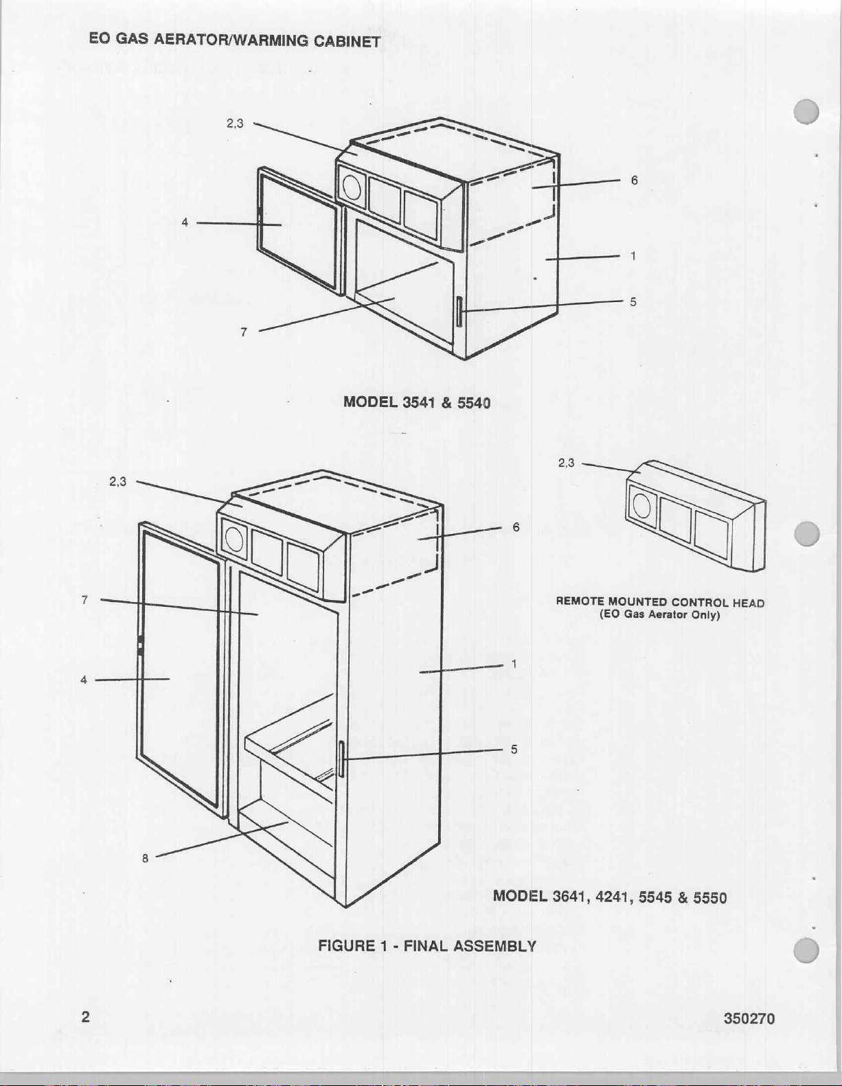
EO
GAS
AERATOR/WARMING
CABINET
q
FIGURE 1 -
FINAL
MODEL
ASSEMBLY
REMOTE
3641,
MOUNTED
Gas
(EO
4241,
Aerator
5545
CONTROL
Only)
&
5550
HEAD
2
350270
Page 93

EO
GAS
AERATOR/WARMING
X
CABINET
K
a
ITEM
Ἱ
2
3
4
5
6
7
9
=
Final
Assembly - Refer
Cabinet
*
See
Control
*
See
Recorder
*
See
Door
+
See
Unit
Components
*
See
Control
*
See
Body
*
See
Frame & Track
*
See
Stand
*
See
DESCRIPTION
Package
Figure 2 for
Head
Figure 3 for listing
Package
Figure 4 for
Assembly
Figure 5 for
Figure 6 for
Box
Components
Figure 7 for
Components
Figure 8 for
Figure 9 for
Package
Figure
listing
Components
(Optional)
listing
Components
listing
listing
listing
listing
Components
listing
(Model
10
for
listing
of
parts
of
parts
of
parts
of
parts
of
parts
of
parts
of
parts
of
parts
3541)
of
to
Figure
(Model
parts
1
3641)
350270
3
Page 94

EO
GAS
AERATOR/WARMING
CABINET
12
13
V
UNIT
BODY
7
5
6
|
|
(2)
DETAIL
(4
Places)
A
\
8
(1)
(SEE
DETAIL
A)
REF.
69117D
350270
Page 95

EO
GAS
AERATOR/WARMING
CABINET
ITEM
一
OC
R
O1
O
~
oo
©
Cabinet
PART
69054
69114
60529
69183
69116
13444
13442
22413
E5186
E6896
59977
E6291
E0152
69197
E2194
NO.
Package
Panel,
Panel,
Panel,
Cover,
Bracket,
Stud,
Washer,
Spring,
Nut,
Screw,
Washer,
Screw,
Washer,
Cover,
Screw,
Right
Side
Left
Cabinet
Panel
Compression,
1/4-20
#10-24 x 3/8
#10-24 x 3/8
Duct
#6-32 x 1/4
(3541
Refer
DESCRIPTION
Side
Extension
Side
Top
Extension
Mounting,
5/16
ID x 1
Hex
#10
Nylon
#10
Internal
Opening
EO
Gas
to
Figure
Panel
Mounting
1/4-20 x 1-1/4 long
OD
Spring
9/16
dia x 3/4
Self-Tapping
Trim
Slotted
Tooth
Self-Tapping
Pan
Lock
Aerator) - 69117
2a
long
Pan
Head
Head
Phillips
Pan
Head
(Chrome)
350270
Page 96
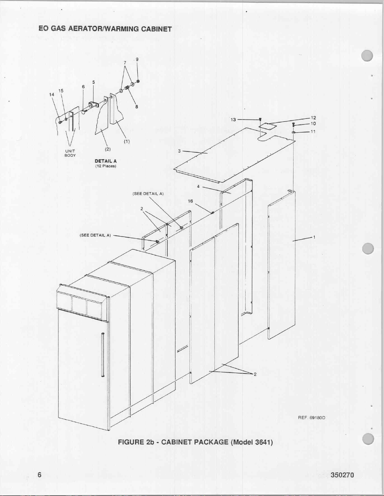
EO
GAS
AERATOR/WARMING
3
CABINET
-9
14
15
|
V
UNUT
BODY
6
(SEE
:
DETAIL
(12
DETAIL
À
1
8
»
(2)
A
Places)
A)
3—4
E—10
se
6
TH
LAR
レイ
ン
FIGURE
|
|
|
|
A
|
2b - CABINET
ーー
a
ささ
PACKAGE
(Model
3641)
N
ВЕР.
691800
350270
Page 97
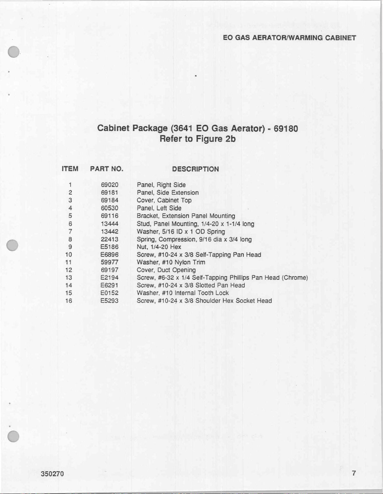
EO
GAS
AERATOR/WARMING
CABINET
C)
ITEM
INDIANA
0
oO
=
一
=
OO
BR の
=
글
σσ
Cabinet
PART
NO.
69020
69181
69184
60530
69116
13444
13442
22413
E5186
E6896
59977
69197
E2194
E6291
E0152
E5293
Package
Refer
Panel,
Panel,
Cover,
Panel,
Bracket,
Stud,
Washer,
Spring,
Nut,
Screw,
Washer,
Cover,
Screw,
Screw,
Washer,
Screw,
Right
Side
Cabinet
Left
Extension
Panel
5/16
Compression,
1/4-20
#10-24 x 3/8
#10
Duct
#6-32 x 1/4
#10-24 x 3/8
#10
#10-24 x 3/8
(3641
EO
to
Figure
DESCRIPTION
Side
Extension
Top
Side
Panel
Mounting,
ID x 1
Hex
Nylon
Opening
Internal
1/4-20 x 1-1/4
OD
9/16
Self-Tapping
Trim
Self-Tapping
Slotted
Tooth
Shoulder
Gas
2b
Mounting
Spring
dia x 3/4
Pan
Lock
Hex
Aerator) - 69180
long
long
Pan
Head
Phillips
Head
Pan
Socket
Head
Head
(Chrome)
@:
350270
Page 98
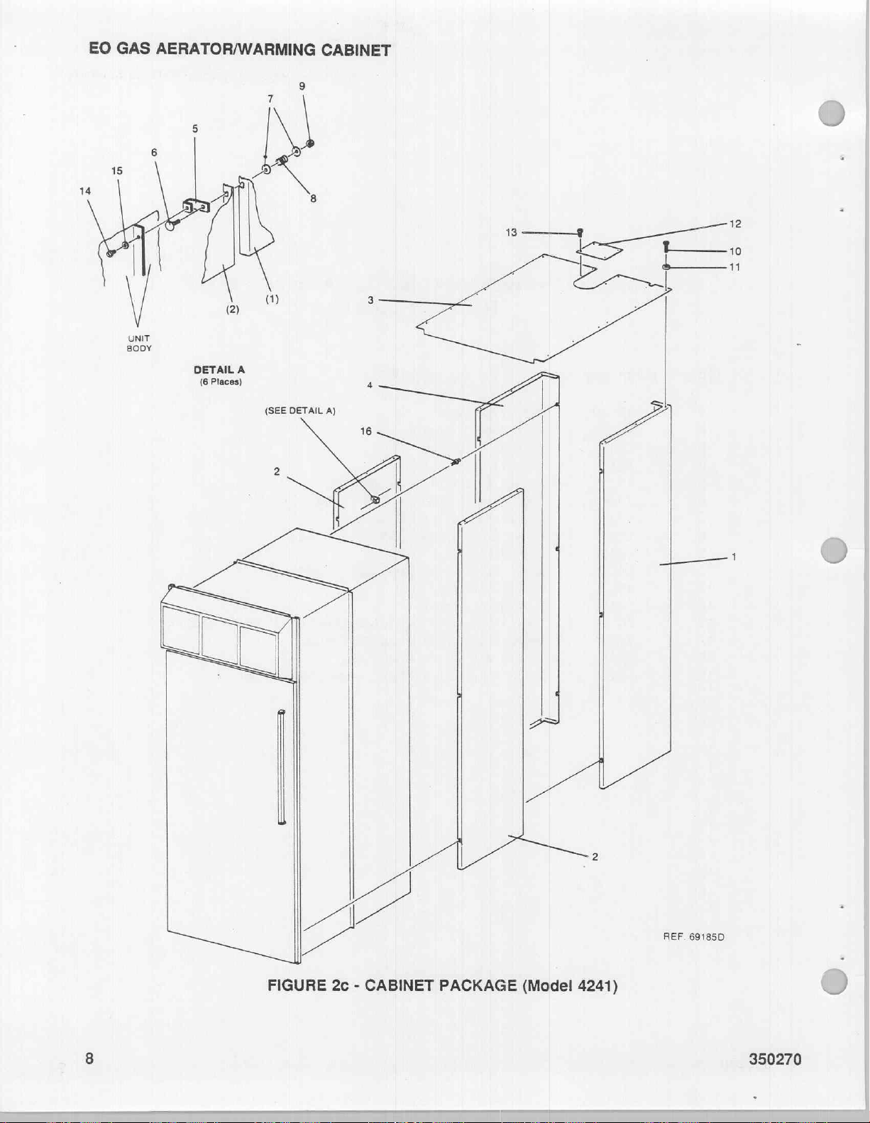
EO
GAS
AERATOR/WARMING
CABINET
レイ
FIGURE
|
ン
2c - CABINET
—
B
PACKAGE
(Model
4241)
REF.
69185D
350270
Page 99
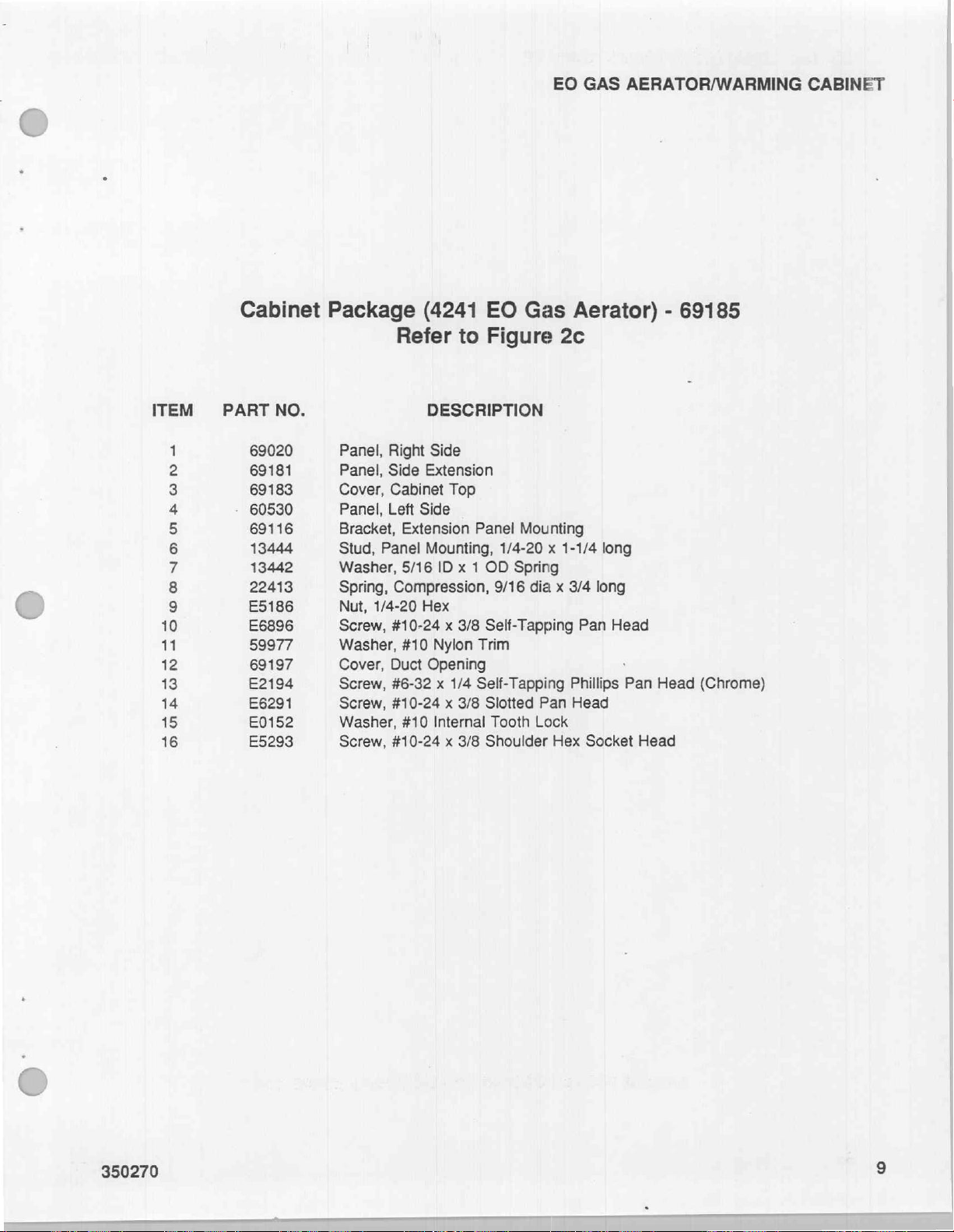
EO
GAS
AERATOR/WARMING
CABINET
O
ITEM
1
2
3
4
5
6
7
8
9
10
11
12
13
14
15
16
Cabinet
PART
69020
69181
69183
60530
69116
13444
13442
22413
E5186
E6896
59977
69197
E2194
E6291
E0152
E5293
NO.
Package
Panel,
Panel,
Cover,
Panel,
Bracket,
Stud,
Washer,
Spring,
Nut,
Screw,
Washer,
Cover,
Screw,
Screw,
Washer,
Screw,
Right
Side
Cabinet
Left
Panel
Compression,
1/4-20
#10-24 x 3/8
Duct
#6-32 x 1/4
#10-24 x 3/8
#10-24 x 3/8
(4241
Refer
DESCRIPTION
Side
Extension
Top
Side
Extension
Mounting,
5/16
ID x 1
Hex
#10
Nylon
Opening
#10
Internal
EO
Gas
to
Figure
Panel
Mounting
1/4-20 x 1-1/4
OD
Spring
9/16
Self-Tapping
Trim
Self-Tapping
Slotted
Tooth
Shoulder
Aerator) - 69185
2c
long
dia x 3/4
Pan
Lock
Pan
Phillips
Head
Hex
Socket
long
Head
Pan
Head
Head
(Chrome)
350270
Page 100

EO
GAS
AERATOR/WARMING
CABINET
nm
ene
FIGURE
A
2d - CABINET
se
PACKAGE
(Model
5550 8 5545)
REF.
69021C
350270
 Loading...