

Page 1

M
fr
へ
SERVICE
MANUAL
©
Castle
5520
5525
C
Г
WARMING
MDT
Diagnostic
1777
Rochester,
5530
CABINETS
E.
Henrietta
PO.
Box
23077
New
York
Company
Road
14692
)
ER
Technology
q
for
Life
30926
Rev.
ノ
C
Page 2
SERVICE
Rev. A (11/
Rev. B (
Rev. C (11/18/87)
For
Complete
Installation
Operators
Parts
MANUAL
9/85)
3/21/86)
Manual
Instructions
Manual
Catalog
PEN)
30927
30926
GRAPHICS
GENERAL
Changed
Add:
30923
Rev.
DESCRIPTION
The
following
“Danger”
(1/18/84)
REVISED:
REVISION
Logos:
30971
Rev.
C
Rev.
B
symbols
notes
Pages
Front & Back
C
OF
SYMBOLS
with
related
apply
when
5,
21, 22, & 25
Covers & p.
&
NOTES
notes
there
is a possibility
ii
appear
IN
in
of
MANUAL
this
manual.
serious
injury
or
death.
“Warning”
“Caution”
NOTE
>
“Notes”
Ne
noreğp>
=
>
notes
notes
ㆍ
alert
the
All
to
This
Corporation,
produced
of
alert
alert
user
parts
the
Castle,
manual
the
MDT
the
user
the
user
to
pertinent
replaced
Rochester,
contains
Rochester,
in
whole
Corporation.
to
to
the
under
or
the
facts
in
possibility
possibility
and
conditions.
warranty
N.Y.,
for
proprietary
New
York,
part
without
of
personal
of
damage
shall
be
returned
evaluation.
information
and
it
shall not
the
written
injury.
to
the
equipment.
intact
of
the
MDT
be
re-
permission
EMDT
and
Castle
are
registered
trademarks.
Page 3
SECTION
GENERAL
1.
(Storage)
Switch
Filter
Will
Power
or
VAC
VAC
Warning
Panel
Recorder
AirFIOW:
МОЕ
Breaker
Not
Connections
Power
Power
Control
Center
Door
Reversible
Shelf
Adjustable
Optional
Temperature
Heatad
2.
WIRING
Warming
TROUBLE
3.
ПОЛ
Circuit
Unit
Jumper
UnitiNot'AtProper
+5V
+11.6V
18
24
Yellow
We
Heater/Fan
ADJUSTMENTS
4.
DESCRIPTION
Compartment
上
1
Door
(Models
Shelves
1
(Models
Conversion
DIAGRAM
Cabinet
Supply
-11.6V
Wiring
ANALYSIS
О
Trips
Up
Heat
Temperature
Problem
Power
Supply
Supply
Lit
Operational
&
TABLE
スー
ユー
トー
ーー
上
上
5530
&
5520
5520 & 5525
....1....%..........1%2...,.....
Chart
see
ee
Diagram
ео
of
J3
on
Supply
Problem
Problem
............
Checks
CALIBRATION
OF
CONTENTS
В
Assembly
Control
-
トー
Only)
Head
ーー
で
ドド
ドド
トド
..............
Only)
ドド
ーー
<
....
elele
e
ola
es
ŞA
lale
e
ele
.......................................
αρ
e
cen
Circuit
Printed
.....................
Problem
haa
ca
Board
...............
er
ドド
siye
ο
aida
emele
ος
aos
поме
оное
이이
이
еее
в
eje
우우
rea
PAGE
о
。
oe
ее
4
6
7
8
9
10
11
12
13
14
15
16
17
30926
Safety
Power
Temperature
DGOrAGiustMment
Recorder
REPAIR
5.
Safety.
Access
Access
Circuit
Fuse
Transformer
Low
EaniReplacemant:
Heater
Thermostat
Door
Recorder
Printed
Relay
Door
Reversing'DoonSwWing.
During
Supply
Calibration
DuringRepaif
Control
to
Control
to
Breaker
Replacement
Voltage
Replacement
Replacement
Switch
Replacement
Circuit
Meplacemente
Gasket
Adjustments
Voltage
Control
Replacement
Replacement
Power
Replacement
Board
Replacement
Calibration
Calibration
“tino
cdr
Head
Box
............
Supply
..........
Replacement
...................:0.x».5
Calibration
&
iene
e
Components
Components
............
.....
Replacement
MMM...
(Optional
Lu.
Equipment)
...............
.......................
....................,............
nie
pronao
ian
...........
........
uen
ο
enni
302
eee
eae
бое
siete
о
nec
sure
eme
sie
ие
Mala
eds
ани
zes
se
mee
ss
Kase
09
é
18
18
19
20
21
23
23
23
23
23
24
24
24
24
24
26
26
26
22
22
27
Page 4
—IMPORTANT—
CAREFULLY
SERVICING
SPECIAL
READ
THE
Do
not
flammable
electrical
cabinet.
explosion
eguipment
THE
UNIT,
STORAGE
store
agents
components
Contact
or
and
SAFETY
FOLLOWING
AND
items
in
the
into
with
fire,
resulting
surroundings.
FOLLOW
DANGER
VT
INSTRUCTIONS
Warming
the
cabinet
designed
an
to
airborne
in
serious
INSTRUCTIONS
INSTRUCTIONS
THE
Cabinet
atmosphere.
heat
flammable
personal
which
and
circulate
INSTRUCTIONS.
(p.
5)
could
This
agent
injury,
introduce
unit
air
within
may
or
damage
contains
BEFORE
the
cause
to
Hot
substances,
cause
may
temperatures
When
burn
contact
Warming
(120°F),
result
could
surfaces
is
ture
above
contact
when
TEMPERATURE
heated
damage
skin
above
to
tissue
49°C
to
skin
STORAGE
Cabinet
interior
with
to
burns
in
removing
49°C
(120°F).
SELECTION
temperatures
tissue.
when
(120°F).
used,
Goods,
should
INSTRUCTIONS
operating
at
is
surfaces
Avoid
skin.
replenishing
or
contact
(p.
above
49°C
solutions,
not
be
(p.
temperatures
heated
of
intertor
with
cabinet
if
stock
4)
(120°F),
etc.,
which
processed
5)
above
compartments
49°C
cabinet
tempera-
may
at
30926
Page 5

5520, 5525, & 5530
WARMING
CABINETS
RECORDER
(OPTIONAL)
REVERSIBLE
DOOR
5520, 5525, & 5530
ENTER
(STORAGE)
COMPARTMENT
=
|
|
DS
|
—
|
MODEL
(CABINET
|
!
LT
|
5520
MODEL)
CONTROL
ASSEMBLY
CONTROL
DOOR
SWITCH
SHELF
FILTER
|
|
>
ADJUSTABLE
BANER
EMO
COMPARTMENT
WARMING
ADJUSTABLE
REVERSIBLE
CENTER
(STORAGE)
CABINETS
RECORDER
(OPTIONAL
SHELVES
DOOR
CONTROL
HEAD
ASSEMBLY
CENTER
RE
SOMEZE
MODEL
(CABINET
5525
MODEL)
μεν
ASSEMBLY
COMPARTMENT
HEATED
DEFLECTOR
ÚNHEATED
COMPARTMENT
CONTROL
PANEL
DOOR
SWITCH
UPPER
HEATED
AIR
LOWER
30926
RECORDER
(OPTIONAL)
CONTROL
PANEL
DOOR
REVERSIBLE
DOOR
SHELF
FILTER
MODEL
(CABINET
5530
MODEL)
SWITCH
MODELS
(RECESSED
5520
MODEL)
&
5525
(RECESSED
MODEL
5530
MODEL)
Page 6
5520,
5525, 4 5530
WARMING
General
CABINETS
Information
6
GENERAL
Castle
are
designed
goods
air
shelves.
36°C
of
solutions,
or
filters
lower
is
heated
partment
range
5520
shelf
also
compartment
to
holding
tions,
dry
compartment
upward
recorder
record
(e.g.
The
evenly
(97°F)
holding
dry
goods
the
shelves.
adjustable.
The
compartment
for
Warming
capacities
the
same.
The
5530
provide
20
or
goods
from
Either
of
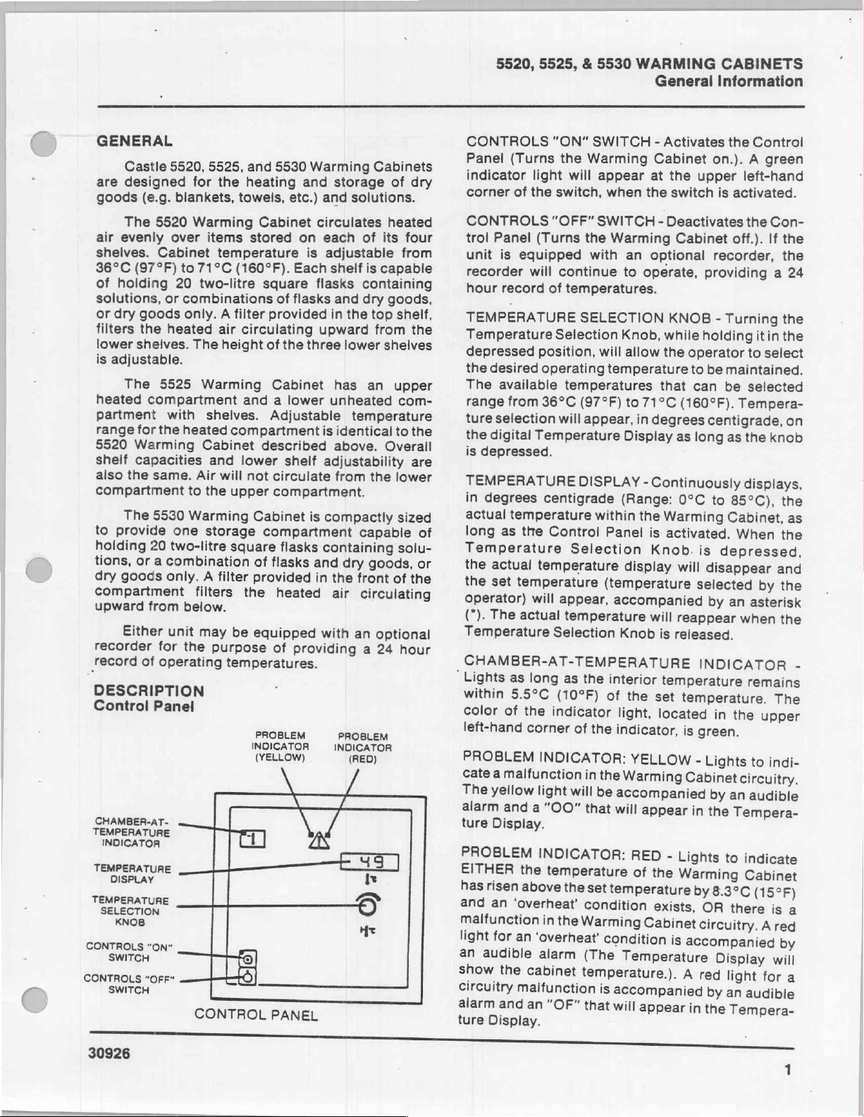
DESCRIPTION
Control
CHAMBER-AT-
TEMPERATURE
INDICATOR
TEMPERATURE
DISPLAY
TEMPERATURE
LON
SONTROLS
В
30926
Font
ώς
ОЕ
5520,
5525,
for
blankets,
5520
Warming
over
items
Cabinet
to
71°C
20
two-litre
or
combinations
only. A filter
heated
The
5525
the
with
heated
to
Warming
one
Warming
shelves.
Cabinet
and
Air
the
storage
two-litre
a
combination
only.
A
filters
below.
unit
may
for
the
purpose
operating
Panel
FT]
CONTROL
and
5530
the
heating
towels,
Cabinet
stored
temperature
(160°F).
square
of
provided
air
circulating
height
will
filter
of
the
Cabinet
and a lower
Adjustable
compartment
described
lower
upper
sguare
be
temperatures.
shelf
not
circulate
compartment.
Cabinet
compartment
flasks
of
flasks
provided
the
heated
eguipped
of
PROBLEM
INDICATOR
(YELLOW)
NY
>
2
PANEL
Warming
and
storage
etc.)
and
circulates
on
each
is
adjustable
Each
shelf
flasks
flasks
and
in
upward
three
has
unheated
is
identical
above.
adjustability
from
is
compactly
containing
and
in
the
air
with
providing
INDICATOR
N
Nød
EST
Cabinets
solutions.
heated
of
its
is
capable
containing
dry
goods,
the
top
from
lower
shelves
an
temperature
Overall
the
capable
dry
goods,
front
circulating
an
optional
a
24
PROBLEM
(RED)
人
ча
^
He
of
dry
four
from
shelf,
the
upper
com-
to
the
are
lower
sized
solu-
or
of
the
hour
of
“Lights
Cate
The
alarm
ture
PROBLEM
EITHER
has
and
malfunction
light
an
show
circuitry
alarm
ture
CONTROLS
Panel
(Turns
indicator
corner
CONTROLS
trol
Panel
unit
is
recorder
hour
record
TEMPERATURE
Temperature
depressed
the
desired
The
available
range
from
ture
selection
the
digital
is
depressed.
TEMPERATURE
in
degrees
actual
long
Temperature
the
the
operator)
(*).
Temperature
temperature
as
actual
set
The
“ON”
the
light
will
of
the
switch,
“OFF”
(Turns
equipped
will
continue
of
temperatures.
Selection
position,
operating
temperatures
36°C
will
Temperature
centigrade
the
Control
Selection
temperature
temperature
will
appear,
actual
temperature
Selection
SWITCH - Activates
Warming
appear
when
SWITCH - Deactivates
the
Warming
with
SELECTION
will
temperature
(97°F)
appear,
DISPLAY
within
Panel
(temperature
accompanied
CHAMBER-AT-TEMPERATURE
as
long
as
the
of
the
in
will
that
interior
of
the
be
within
color
left-hand
5.5ºC
of
PROBLEM
a
malfunction
yellow
and
(10ºF)
the
indicator
corner
INDICATOR:
light
a
“OO”
Display.
uj
INDICATOR:
the
temperature
risen
abovethe
an
‘overheat’
for
an
audible
the
malfunction
and
Display.
in
‘overheat’
alarm
cabinet
an
set
condition
the
Warming
condition
(The
temperature.).
is
“OF”
that
temperature
accompanied
will
Cabinet
at
the
the
switch
Cabinet
an
optional
to
operate,
KNOB - Turning
Knob,
while
allow
the
that
to
71°C
in
degrees
Display
-
(Range:
display
Knob
the
light,
indicator,
as
Continuously
the
Warming
is
activated.
Knob.
will
will
reappear
is
released.
temperature
set
located
YELLOW
Warming
accompanied
will
appear
RED
-
Lights
of
the
Warming
exists,
Cabinet
is
Temperature
appear
the
on.). A green
upper
left-hand
is
activated.
the
off.).
recorder,
providing a 24
holding
operator
to
can
(160°F).
long
0°C
to
be
maintained.
be
selected
Tempera-
centigrade,
as
the
displays,
to
85°C),
Cabinet,
When
is
depressed,
disappear
selected
by
an
when
INDICATOR
remains
temperature.
in
the
is
green.
-
Lights
Cabinet
in
by
the
circuitry.
an
Tempera-
to
indicate
Cabinet
by
8.3°C
OR
there
circuitry.
accompanied
Display
A
red
light
by
an
audible
in
the
Tempera-
Control
Con-
If
the
the
the
it
in
the
select
on
knob
the
as
the
and
by
the
asterisk
the
The
upper
to
indi-
audible
(15°F)
is
a
Ared
by
will
for
a
°
-
Page 7
§520, 5525, & 5530
1.
General
Information
WARMING
CABINETS
Center
(Storage)
Assembly-
This
compartment
access
tridges,
Door
this
to
switch
heating
Reversible
the
desired, a door
in
the
should
personnel.
Shelf
Switch
Closing
switch
the
heating
A
Warming
left
the
opposite
door
Filter
storage
etc.
the
and
will
be
circuit
Door
or
right,
swing
only
(Models
Filters the
compartment.
Adjustable
Shelves
Compartment - Control
may
be
of
recorder
Warming
allow
electrical
circuit.
released
will
be
When
be
Cabinet
depending
may
be
direction.
are
in
undertaken
shut
converted
charts,
Cabinet
power
the
door
and
electrical
off.
door
swings
on the
Instructions
this
Service
by
5520 4 5530
upward
flow
(Models
of
heated
5520 4 5525
used
for
ink
pen
door
will
to
be
is
opened,
power
open
individual
so
it
swings
for
reversing
Manual,
Castle
Only)
air
Head
ready-
car-
depress
supplied
this
to
the
either
to
unit.
open
and
Service
into
Only)
If
a
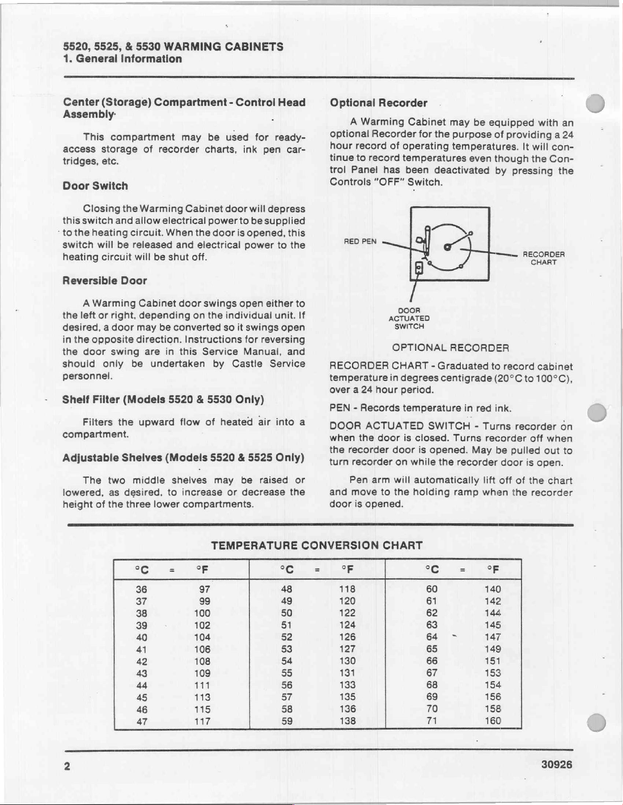
Optional
optional
hour
tinue
trol
Controls
RED
RECORDER
temperature
over a 24
PEN - Records
DOOR
when
the
turn
Recorder
A
Warming
Recorder
record
to
record
Panel
"OFF"
PEN
hour
ACTUATED
the
door
recorder
recorder
of
has
|
ACTUATED
in
Cabinet
for
operating
temperatures
been
Switch.
may
be
the
purpose
temperatures.
even
deactivated
So
:
/
DOOR
SWITCH
OPTIONAL
CHART - Graduated
degrees
period.
temperature
is
closed.
door
is
on
while
RECORDER
centigrade
in
SWITCH - Turns
Turns
opened.
the
May
recorder
equipped
of
providing a 24
though
by
-—_
to
record
(20°C
red
ink.
recorder
be
door
with
It
will
the
pressing
RECORDER
am
cabinet
to
100°C),
recorder
off
pulled
is
out
open.
an
con-
Con-
the
on
when
to
The
lowered,
height
of
two
middle
as
desired,
the
three
°C
36
37
38
39
40
41
42
43
44
45
46
47
shelves
to
lower
=
may
increase
compartments.
or
TEMPERATURE
oF
97
99
100
102
104
106
108
109
111
113
115
117
be
raised
decrease
or
the
CONVERSION
°C
48
49
50
51
52
53
54
55
56
57
58
59
and
door
°F
118
120
122
124
126
127
130
131
133
135
136
138
Pen
move
is
arm
to
opened.
CHART
will
automatically
the
holding
°C
60
61
62
63
64
65
66
67
68
69
70
71
ramp
=
>
lift
when
°F
140
142
144
145
147
149
151
153
154
156
158
160
off
the
of
the
recorder
chart
Page 8
§520, 5525, & 5530
WARMING
CABINETS
Operation
o
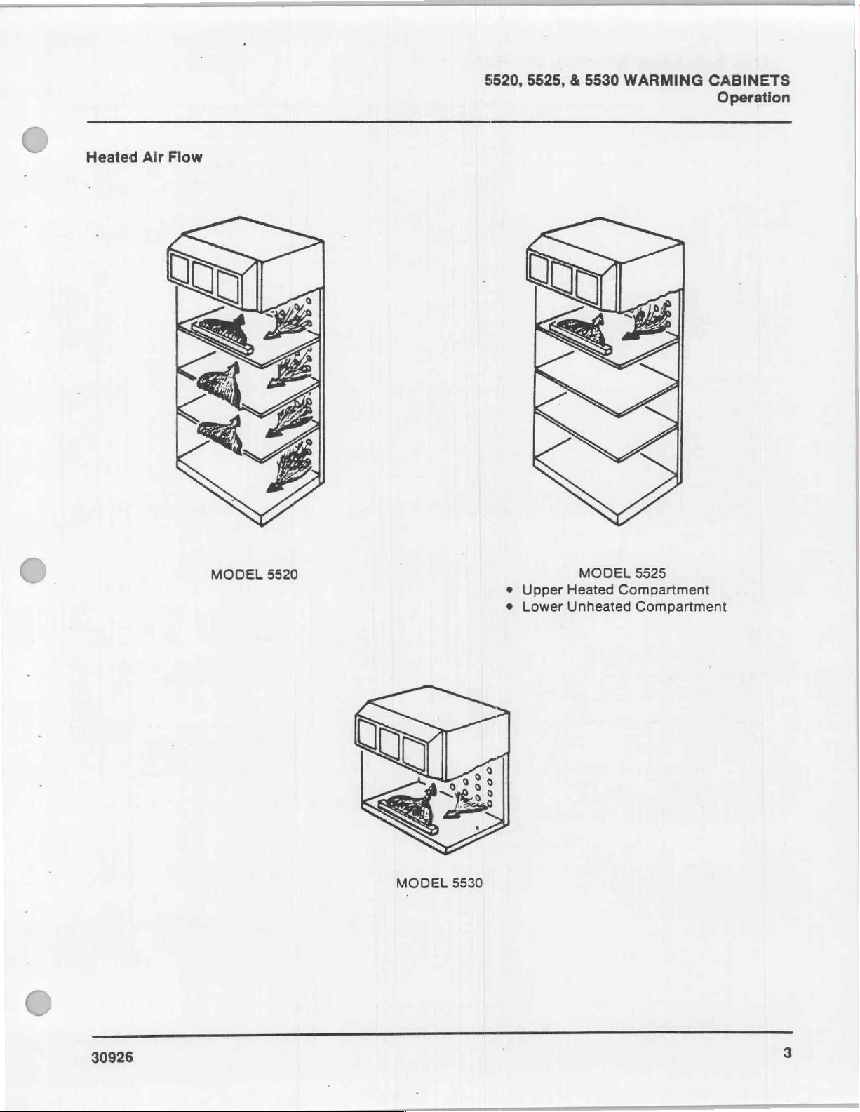
Heated
Air
Flow
MODEL
5520
|
MODEL
5530
e
e
Upper
Lower
MODEL
Heated
Unheated
5525
Compartment
Compartment
30926
Page 9
5520,
2.
5525, & 5530
Wiring
Diagram
WARMING
CABINETS
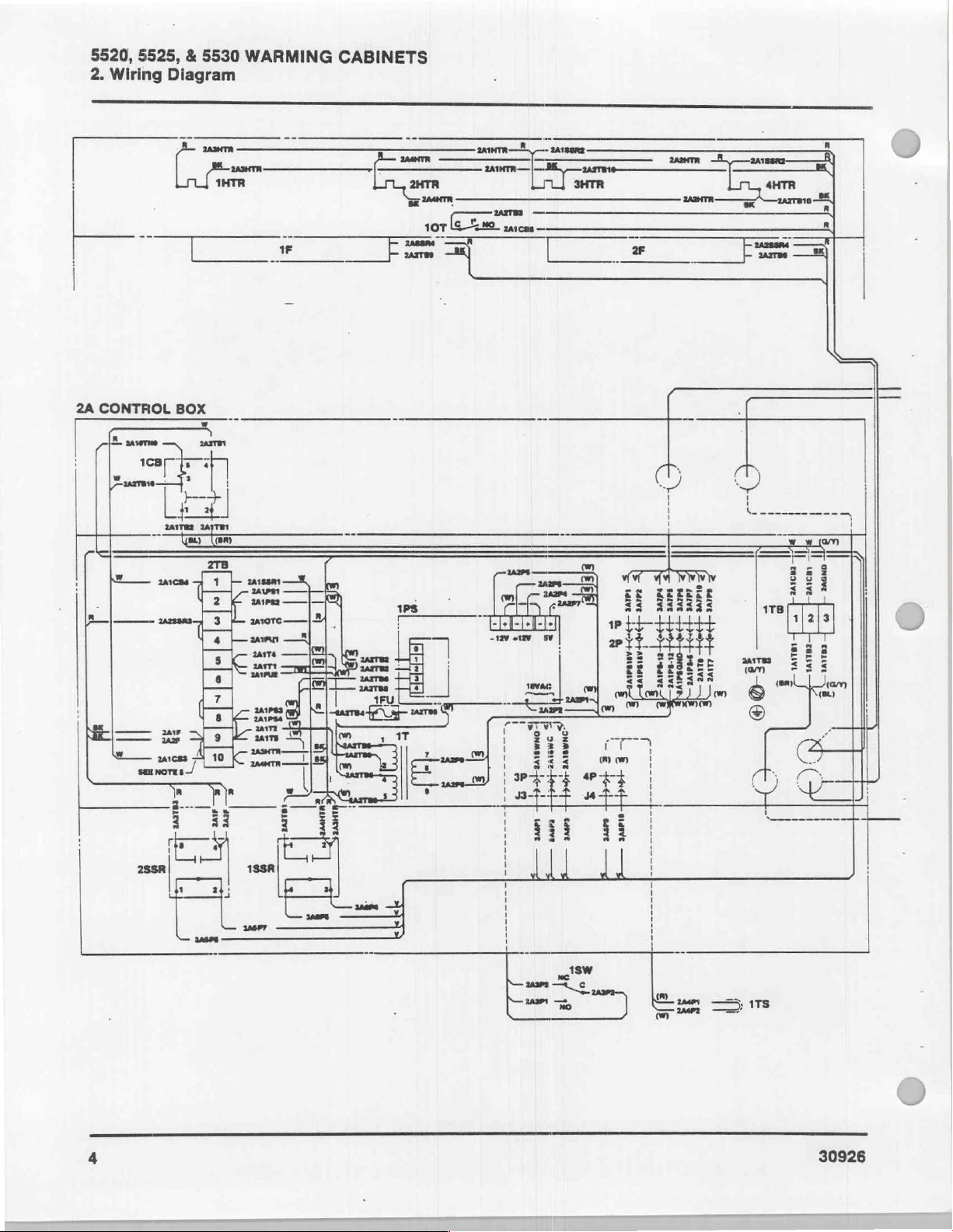
2A
CONTROL
fm
BOX
um
_
É
ZU
333
ЕН
PI
TTT
313
Li
|
ЕЕ
ЗЕЕЕЕЕ
33
333333
wit
it
tit
LESLEY
z
=
きま ま E3SEEE
日
=
ГГ
a
2
da
хх
|
|
ㅣ
|
i
!
|
|
1
i
i
1
i
o
z
SH
u
M!
|
U
το
ww
f
178
om
‘am < ミミ
©"
e
©
(ay)
Πρ
ὅτι ||
Bala
Tir
EEE
OÚ
SE
i
(BL)
(am
>
|
)
上
ii
|
ú
Hi
3/8
d
l
30926
Page 10
Ê
=
|
1A
Lee,
|
ann
3
arre
POWER
1TB
|
IT 一 -
i-
5A
SUPPLY
區
-
RECORDER
παν
super
{
une
5520, 5525, & 5530
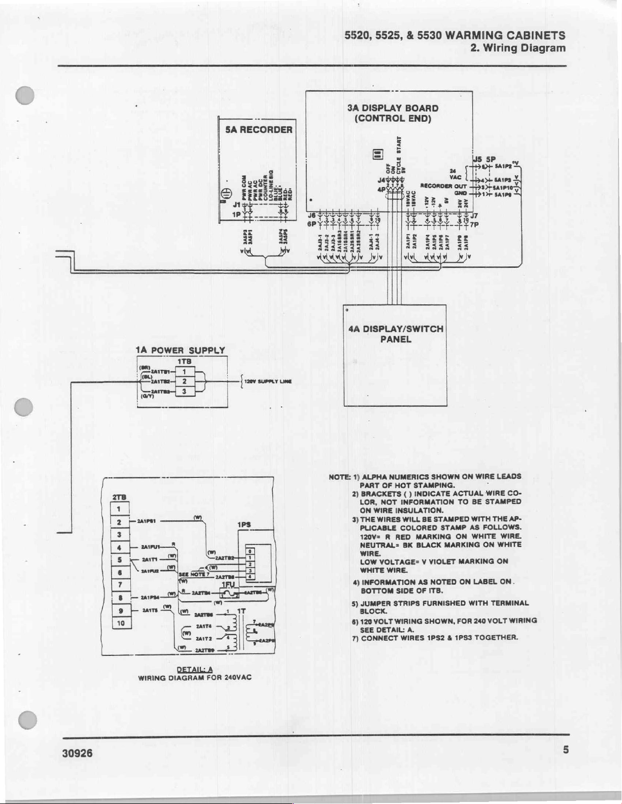
3A
DISPLAY
(CONTROL
-
什
+
ed
|
1
Ke《
Ke
一
二
-K
et
2A188R4
2A188R3
2
9
4A
DISPLAY/SWITCH
PANEL
BOARD
END)
WARMING
sv
stay
ar
ad}
acil
각서
2Atp4
2a1P6
Hav
|
24107
14109
2.
Wiring
24Y
于
2A1P8
CABINETS
Diagram
30926
ejelsjajujajuln
WIRING
DETAIL
DIAGRAM
A
FOR
240VAC
NOTE:
1)
ALPHA
PART
OF
2)
BRACKETS ( )
LOR,
NOT
ON
WIRE
3)
THE
WIRES
PLICABLE
120V= R RED
NEUTRAL=
WIRE.
LOW
VOLTAGE= V VIOLET
WHITE
WIRE.
4)
INFORMATION
BOTTOM
5)
JUMPER
BLOCK.
6)
120
VOLT
SEE
DETAIL:
7)
CONNECT
NUMERICS
HOT
STAMPING.
INDICATE
INFORMATION
INSULATION.
WILL
COLORED
MARKING
BK
BLACK
SIDE
OF
STRIPS
WIRING
A.
WIRES
SHOWN
BE
STAMPED
STAMP
MARKING
AS
NOTED
ITB.
FURNISHED
SHOWN,
1PS2 & 1PS3
ON
ACTUAL
TO
ON
MARKING
ON
WITH
FOR
WIRE
i
WIRE
BE
STAMPED
WITH
THE
AS
FOLLOWS.
WHITE
ON
LABEL
TERMINAL
240
VOLT
TOGETHER.
LEADS
CO-
AP-
WIRE.
WHITE
ON
ON.
WIRING
Page 11
5520,
3.
Trouble
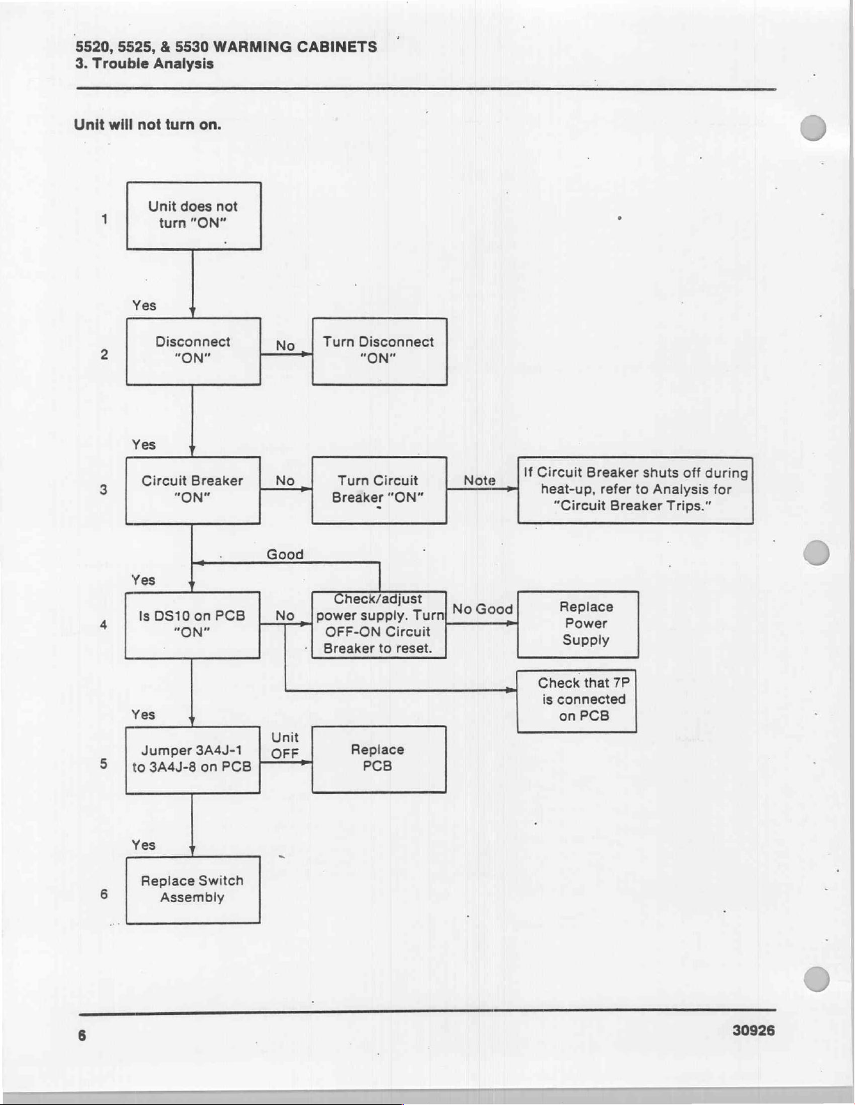
Unit
will
1
5525, & 5530
Analysis
not
turn
Unit
turn
on.
does
“ON”
WARMING
not
CABINETS
°
Yes
2
Yes
3
4
5 | to
e
Yes
Is
Yes
Jumper
Disconnect
"ON"
м
DS10
on
PCB | No,
ER"
"ON
3A4J-1
3A4J-8
on
a
PCB
No | Turn
Good
No
Unit
OFF
deo,
Check/adjust
|power
OFF-ON
Breaker
Disconnect
"ON"
V.
=
supply.
a.
Circuit
to
reset.
Replace
PCB
Turn}
NE
No
If
Circuit
heat-up,
“Circuit
Good
Replace
Check
is
connected
on
Breaker
Power
Subo!
PPY
that
PCB
refer
Breaker
7P
shuts
to
Analysis
Trips.”
off
during
for
Yes
Replace
6
6
Switch
Assembly
30926
Page 12
5520,
5525, & 5530
WARMING
3.
Trouble
CABINETS
Analysis
(
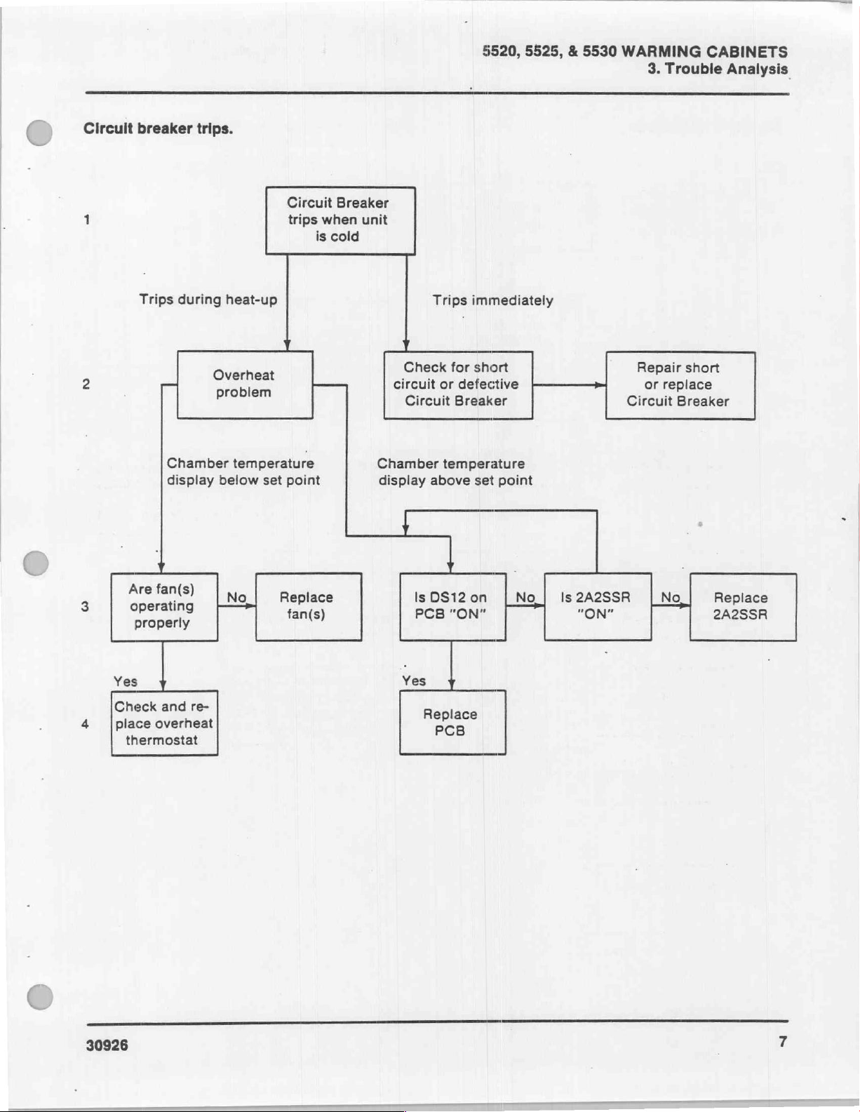
Circuit
1
2
breaker
Trips
during
Chamber
display
trips.
Circuit
trips
heat-up
Overheat
problem
temperature
below
set
point
when
is
cold
Breaker
unit
Chamber
display
Trips
immediately
1
πώς
Circuit
above
ον
Breaker
temperature
set
ft
point
Hi
Circuit
P
Breaker
Yes
Check
place
4
Are
one
operating
properly
and
overheat
thermostat
No | Replace
re-
fan(s)
ls
DS12on | No | ls2A2SSR | No | Replace
PCB
"ON"
Yes
y
Replace
PCB
2A2SSR
30926
Page 13
5520,
3.
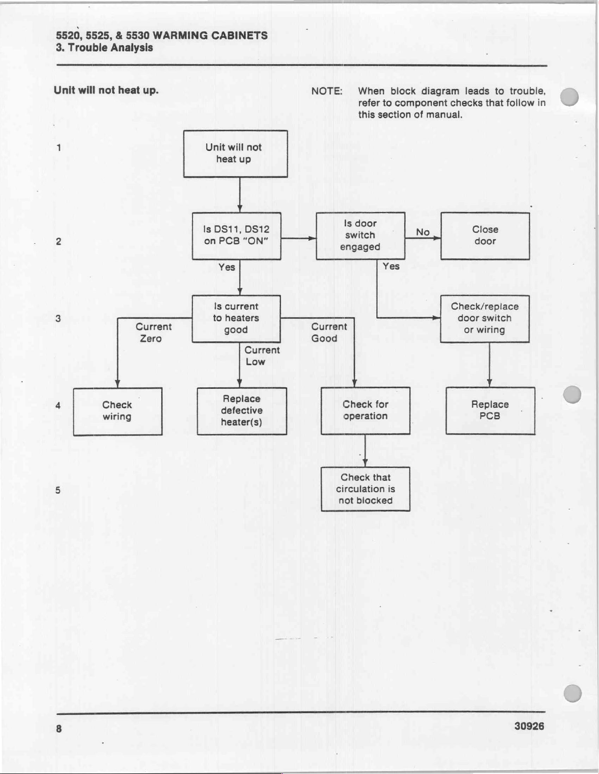
Unit
2
3
5525, & 5530
Trouble
will
1
Analysis
not
heat
WARMING
up.
Current
Zero
CABINETS
Unit
Is
S
on
to
will
not
heat
up
DS11,
Is
PCB
"ON"
PCB
Yes
current
heaters
good
DS12
Current
Low
NOTE:
Current
Good
When
refer
this
taser
switch
engaged
block
to
component
section
Yes
diagram
of
manual.
No
leads
checks
οι
E
oor
Check/replace
door
or
wiring
to
that
follow
을
switch
trouble,
in
4
5
Y
Check
wiring
bel
heater(s)
| 4
Check
operation
Check
circulation
not
for
that
blocked
is
Replace
PCB
3
30926
Page 14

§520,
‘
Jumper
proper
follows:
Connections
Jumpers
operation
on
J3
of
of
a50
the
on
J3
printed
Hz
or
of
Printed
circuit
60
Hz
supply
3
J6 J7
==
Circuit
board
circuit.
CUT-OUT
(Time
Selector
Switch)
ES
5525, & 5530
Board
must
be
Proper
properly
connections
WARMING
3.
connected
Trouble
for
are
as
CABINETS
Analysis
MIE)
д
|
add
wle—
а
во
a
50/60
JUMPER
33
e
|<
|<
|< >|
|<
HZ
CONNECTIONS
>
>
>
)
5
so
30926
Page 15
5520,
3.
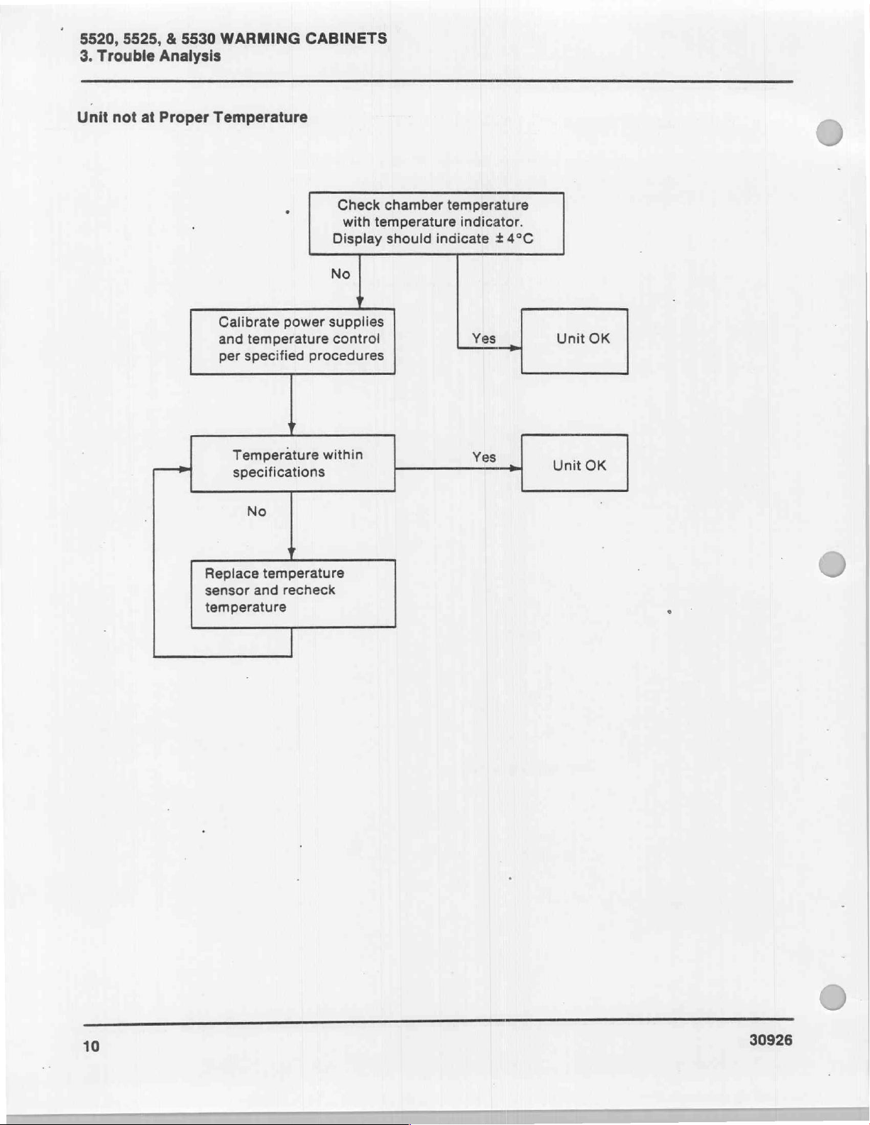
Unit
5525, & 5530
Trouble
not
at
Analysis
Proper
WARMING
Temperature
Calibrate
and
per
power
temperature
specified
CABINETS
Check
with
Display
No
у
supplies
control
procedures
chamber
temperature
should
temperature
indicate + 4°C
indicator.
Yes
Unit
OK
Temperature
specifications
No
Replace
sensor
temperature
temperature
and
y
Y
recheck
within
Yes
Unit
OK
10
30926
Page 16

+5V
Power
Supply a Problem
5520,
5525, & 5530
WARMING
3.
Trouble
CABINETS
Analysis
less
than
Check
good
good
good
ysis.
turn
Turn
breaker
Recalibrate
fied
Check
place
if
required.
y
Trouble
"Unit
on.”
procedure.
will
off
circuit
to
reset
у
per
Still
y
wiring
power
and
supply
Anal-
not
Still
low
OVP
Still
low
speci-
low
re-
+5V
y À
+5V
supply
5.00V + .01V
ibration
procedure.
=+5V
|
Power
supply
not
per
good.
at
cal-
greater
Recalibrate
fied
Replace
than
+5V
Y
per
procedure.
Unable
calibrate
power
speci-
to
supply
good
30926
1
Page 17

5520, 5525, & 5530
3.
Trouble
Analysis
WARMING
CABINETS
+11.6
Good
Good
or
-11.6
Power
Check
ysis
“Unit
will
Recalibrate
fied
procedure
Check
power
inals
Supply
0
or
Trouble
not
Still
plow
per
Still
low
voltage
supply
Voltage
good
low
Anal-
turn
V
speci-
V
at
term-
Problem
voltage
on”
Supply
-11.6
spectively
Power
Voltage
is
voltage
or
+11.6V
supply
0
not
re-
Voltage
Correct
good
at
Voltage
is
higher
Recalibrate
supply
Replace
supply
value
L
power
Unable
calibrate
y
power
to
Good
Good
Good
12
Repair
Check
tage
Check
Replace
supply
faulty
input
to
AC
power
input
power
wiring
vol-
supply
wiring
Input
voltage
OK
30926
Page 18

5520,
5525, & 5530
WARMING
3.
Trouble
CABINETS
Analysis
18VAC
Power
Voltage
Check
ysis
“Unit
will
Check
power
to
Supply
less
than
Problem
18
VAC
18
not
VAC
at
power
18
VAC
1
supply
+4
Voltage
correct
VAC
Voltage
more
Trouble
1 1
input
Anal-
not
turn
Still
low
voltage
supply
Input
incorrect
on”
Input
Voltage
good
OK
power
supply
Check
supply
Replace
than
that
power
input
power
18
VAC
is
correct
supply
183008
Check
Replace
wiring
power
.
supply
30926
13
Page 19

5520,
3.
Trouble
24V
Voltage
DI
9
Voltage
good
Voltage
good
5525, & 5530
Analysis
Power
Supply
Check
ysis
“Unit
Check
and
Check
WARMING
Problem
Trouble
will
not
:
input
wiring
if
Voltage
turn
Voltage
low
voltage
Voltage
low
fuse
is
Anal-
on”
bad
CABINETS
low
24
24
24V
VAC
supply
VAC
+5V
transformer
not
good
at
Voltage
Check
Replace
high
input
transformer
wiring
24V
good
Voltage
good
14
Check
Replace
24V
wiring
transformer
30926
Page 20

Yellow
Warning
Lit
Yellow
00
play
Is
ply
Warning
in
temperature
1
-11.6V
good? power
power
code,
dis-
sup-
No
§520, 5525, & 5530
Adjust
or
supply
replace
WARMING
3.
Trouble
CABINETS
Analysis
Disconnect
PC
board.
>
Check
shorts.
erature
Replace
sensor.
Yes
P6
from
code
sull
No
wiring
for
temp-
Yes
Fieplace
PC
board
30926
15
Page 21
5520,
3.
Trouble
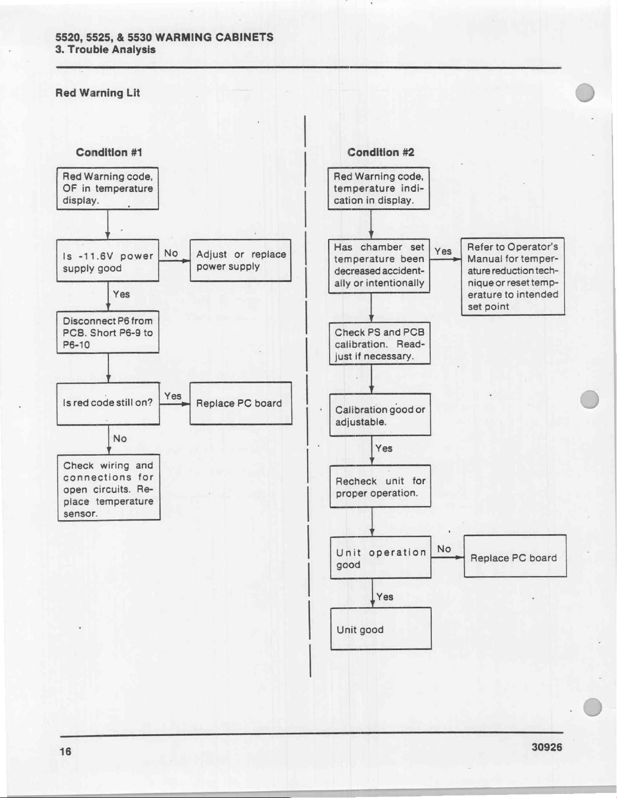
Red
Warning
5525, & 5530
Analysis
Lit
WARMING
CABINETS
Condition
Red
Warning
OF
in
temperature
display.
-11.6V
Is
Short
red
code
circuits.
temperature
good
wiring
supply
Disconnect
PCB.
P6-10
Is
Check
connections
open
place
sensor.
#1
code,
power
Yes
1
P6
from
P6-9
still
on?
No
and
Re-
Adjust
|
NO
|
to
for
Yes
power
Replace
replace
or
supply
PC board
Condition
Red
Warning
temperature
cation
Has
temperature
decreased
ally
Check
calibration.
just
Calibration
adjustable.
in
chamber
or
intentionally
PS
if
necessary.
Recheck
proper
Unit
good
display.
accident-
and
1
Yes
operation.
operation
#2
code,
indi-
been
PCB
Read-
good
unit
set
or
for
Yes
No
Refer
Manual
ature
nigue
erature
set
Replace
to
Operator's
for
temper-
reduction
or
reset
to
intended
point
PC
tech-
temp-
board
16
Yes
Unit
good
30926
Page 22

HEATER/FAN
Check
も
controls
OPERATIONAL
that
circuit
"ON"
switch
breaker
and
CHECKS
is
“ON”,
close
the
press
door.
the
5520,
Open
out
(off).
Close
5525, & 5530
chamber
chamber
door.
door.
WARMING
3.
Trouble
DS11
and
CABINETS
DS12
Analysis
should
go
O
Set
at
chamber.
DS11
circuit
fans
"ON."
and
are
COMPONENT
temperature
DS12
board)
"ON"
DS12
should
and
DS11
J6
to
require
on
the
display
be
lit.
DS12
CUT-OUT
Já
LOCATIONS
DS11
that
bo
heat-up
PCB
indicates
the
heaters
&
POWER
(Other
J7
ON
PCB
of
(printed
LED
Side
+
the
the
are
of
(DS9)
PCB)
Check
a.
Check
2A2SSR4
Voltage
and
closed.
b.
Place
With
be
0.1A
Check
a.
Check
2A1SSR2
VAC
240
b.
Place
2A1SSR2.
age
supply
supply.
fan
electrical
voltage
should
either
amprobe
the
0.2A
on a 240
heater
with
VAC
amprobe
should
or
with a DVM
be 0 VAC
120
or
on
door
closed,
on a 120
VAC
electrical
voltage
with a DVM.
the
door
with
the
on
With
the
be
4.5A
2.25A
supply
circuit.
between
(digital
240
VAC
2A1F
and
the
VAC
electrical
electrical
supply
between
Voltage
open
door
closed.
2A4HTR
door
on a 120
on a 240
2A2TB10
with
the
with
2AF2
amperage
supply.
circuit.
2A2TB10
should
and
either
and
closed,
VAC
VAC
and
voltmeter).
door
open
the
door
of
2SSR4.
should
supply
2A3HTR
the
electrical
electrical
or
and
be
120
or
or
amper-
0
©
30926
17
Page 23

5520, 5525, & 5530
4.
Adjustments & Calibration
WARMING
CABINETS
SAFETY
CALIBRATION
TEMPERATURE
If
required, a temperature
changing
on
Page 2 of
POWER
1.
2.
degrees
SUPPLY
Raise
the
Remove
head
assembly
components.
DURING
The
power
electrical
Prevent
which
personal
during
adjustments
the
could
contact
adjustments
CONVERSION
Celsius
this
manual.
VOLTAGE
control
the
three
for
head
screws
ADJUSTMENTS
circuit
access
must
possibility
cause
injury,
with
and
conversion
to
degrees
CALIBRATION
assembly
that
to
the
be
“ON”
to
and
calibrations.
of
electrical
by
not
electrical
calibration.
CHART
chart
Fahrenheit
cover.
secure
the
the
power
make
shock,
making
circuit
,
for
power
supply
&
is
+5
Volt
a.
Place
probe
-Pin 7 of
b.
Adjust
power
is
+11.6
a.
Place
the
b.
Adjust
power
Vdc
-11.6
a.
Place
the
b.
Adjust
until
Adjustment
DVM
on
the
supply
+5.00
Volt
Adjustment
DVM
positive
the
supply
on
the
Volts
Calibration
DVM
positive
the
the
(digital
J1 - Pin 6 and
the
PCB.
+5V
adjustment
until
+0.01
Vdc
on
negative
probe
on
+11.6V
until
meter.
negative
probe
-11.6V
DVM
POT
reading
voltmeter)
positive
the
reading
the
meter.
probe
adjustment
the
on
on
J1 - Pin
reading
probe
on
J1 - Pin 8 of
on
the
is
-11.6
negative
probe
on
POT
on
the
on
the
DVM
J1 - Pin 6 and
10
of
the
PCB.
POT
on the
is
11.6
+0.01
J1- Pin 6 and
the
PCB.
power
+0.01
supply
Vdc.
>
J1
3.
Check
engaged
switch
temperature
for
that
to
on
the
15
minutes.
ADJUSTABLE
the
"ON."
front
in
the
circuit
Press
panel
Warming
VOLTAGE
breaker
the
controls
to
“ON”
Cabinet
POTS
has
and
been
“ON”
let
the
stabilize
DOT
ON
INDICATES
LOCATION
PC
BOARD
PIN1
J2
J 自 中
@
1
on
Nour
OF
J1
CUT-OUT
J1
ON
PC
14
13
12
11
10
BOARD
18
30926
Page 24

After
making
ments,
‘a.
check
Depress
on the
should
18
VAC
a.
Connect
Pin
2.
b.
DVM
24
VAC
a.
Connect
Pin
10.
b.
DVM
TEMPERATURE
Calibrate
U
under
Power
making
Adjust
a.
b.
R23
R26 R28
the
2.5
Connect a DVM
probe
J1 - Pin
Adjust
reading
HO
ro
the
for
the
front
read
from
Voltage
DVM
reading
Voltage
DVM
reading
CONTROL
the
power
Supply
Temperature
Vdc
on
to
J1 - Pin 6 and
2.
R28
of
2.500
power
proper
temperature
control
supply
adjustments
panel
36°
to
Check
probes
should
Check
probes
should
between
be
between
be
supply
Voltage
Control
the
PCB
(digital
if
required
+0.005
voltage
as
set
point
and
the
71°C.
J7 - Pin 1 and
18.00
+3
-0
J7 - Pin 9 and
24.00
+6
-0
CALIBRATION
voitage
Calibration
display.
voltmeter)
the
to
Vdc.
J1
as
Calibration.
positive
provide a DVM
J2
I
adjust-
follows:
control
display
VAC.
VAC.
outlined
before
negative
probe
to
CUT-OUT
§520, 5525, & 5530
Connect a temporary
J1 - Pin
control
Connect a jumper
Adjust
Remove
NOTE]
Procedure
Procedure | requires
vide
0°C
temperature
o
Remove
trol
PCB
ture
TS
Immerse
R41
the
temperature
Immerse
Adjust R40
same
the
to
Repeat
accurate
12
to
display.
R23
jumper
One
used
which
ture
|
and a boiling
for
the
box
assembly.
and
jumper
sensor)
to
J6
-Pin
tip of
so
that
bath
temperature.
tip of
as
the
bath
temperature
read
1000.
Steps 2 and 3 three
adjustment.
WARMING
4.
Adjustments & Calibrations
jumper
turn
on
third
digit
from
top
of
so
that
the
display
between
of
two
calibration
to
calibrate
is a continuation
Control
water
immersing
temperature
the
to
J6 - Pin 9 and
R29
the
Calibration
an
ice/water
bath
the
temperature
sensor
Remove
red
wire
CABINETS
from
J1 - Pin 3 to
in
temperature
R29
to
reads
and
J1 - Pin
procedures
temperature
of
the
Instructions.
bath
to
provide
from
plug
J6
of
TS
the
white
10.
TS
in
the
the
is
so
bath
0.5°C,
display
TS
that
ice/water
reading
For
adjust
display
in
the
boiling
the
display
temperature.
is
100.0°C,
bath.
is
the
example,
to
water
reading
For
example,
adjust
times
J1 - Pin
000.
6.
may
6.
be
sensor
Tempera-
to
pro-
100°C
sensor.
the
con-
from
the
(tempera-
wire
of
Adjust
same
as
if
bath
read
005.
bath.
is
the
display
to
assure
if
i
3.
30926
LOCATION
Adjust
a.
b.
2.0
Connect
and
Adjust
reading
Vdc
the
COMPONENTS
OF
on
DVM
a
positive
if
R26,
of
2.000
the
PCB
display.
to
to
Vdc.
probe
J1
negative
probe
reguired,
+0.005
PCB
ON
to
1.
Pin
-
provide
J1
-
a
|
Pin
DVM
6
Reassemble
trol
box
assembly.
Reconnect
jumper
from
the
temperature
J6
to
the
J1 - Pin 3 to
sensor
PCB
J1 - Pin
and
to
the
remove
12.
con-
the
19
Page 25

5520,
5525, & 5530
4.
Adjustments & Calibrations
WARMING
CABINETS
Procedure
Procedure
supply
1.
2:
from 0 to 5 Vdc.
Disconnect
Connect
-Pin
Adjust
and
000.
Adjust
and
1000.
Repeat
adjustment.
Remove
PCB,
J1 - Pin
Il
II
requires
plug
J6
power
10.
power
10
of
power
10
of
J6.
Steps 3 and 4 to
power
and
supply
J6.
Adjust
supply
Adjust
remove
supply + to
supply,
the
12.
an
from
PCB.
to
2.730
R41
for
to
3.730
R40
for a display
reconnect
jumper
adjustable
J6 - Pin
Vdc
across
display
Vdc
across
assure
from
power
9,
and
to
Pins
reading
Pins
reading
accurate
plug
J6
J1 - Pin3
J6
9
of
9
of
to
to
DOOR
Loosen
27
hinge
hinges
Place
square
ing
Tighten
ADJUSTMENT
and
to
blocking
and
Cabinet.
hinges
to
the
the
the
the
two
hex
the
lower
Warming
under
aligned
hex
Warming
head
with
head
screws
hinge
Cabinet.
the
door
the
front
screws
Cabinet.
that
that
on
the
secures
so
that
of
the
secure
upper
the
it
Warm-
the
is
20
30926
Page 26
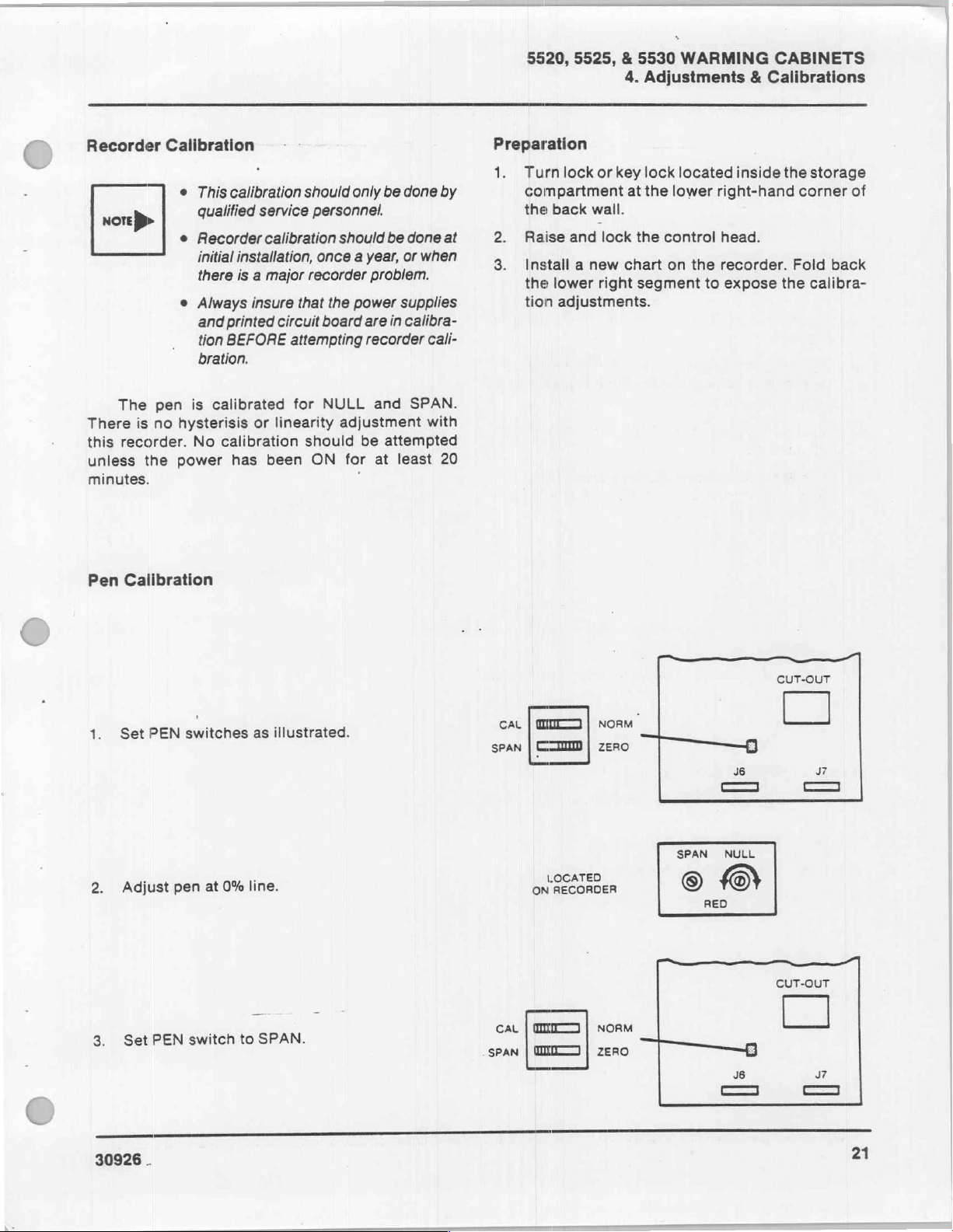
Recorder
x
ore
>
The
There
this
unless
minutes.
is
recorder.
the
Calibration
e
This
qualified
e
Recorder
initial
there
e
Always
and
tion
bration.
pen
is
calibrated
no
hysterisis
No
calibration
power
calibration
service
calibration
installation,
is a major
insure
printed
BEFORE
has
circuit
attempting
or
linearity
been
that
for
should
should
only be
personnel.
should
once a year,
recorder
the
power
board
are
recorder
NULL
adjustment
be
ON
for
i
done
be
done
or
when
problem.
supplies
in
calibra-
and
SPAN.
attempted
at
least
by
at
cali-
with
20
5520, 5525, & 5530
Preparation
1.
Turn
lock
compartment
the
back
wall.
Raise
and
Install a new
the
lower
tion
adjustments.
WARMING
4.
Adjustments & Calibrations
or
key
lock
at
lock
chart
right
the
lower
the
control
on
segment
located
right-hand
head.
the
recorder.
to
expose
inside
CABINETS
the
storage
corner
Fold
the
calibra-
of
back
Pen
Calibration
1.
Set
2.
Adjust
3.
Set
PEN
PEN
switches
pen
at
switch
0%
as
illustrated.
line.
to
SPAN.
CAL
SPAN
CAL
SPAN
mm
CI
LOCATED
RECORDER
ON
mm
mr
|
|
|
|
NORM
ZERO
NORM
ZERO
CUT-OUT
SPAN
NULL
GO
RED
©)
CUT-OUT
30926
.
21
Page 27

5520,
4.
4.
5.
6.
7.
5525, & 5530
WARMING
Adjustments & Calibrations
line.
100%
to
Adjust
Repeat
required.
Again
tion
Set
pen
Steps 1 thru 4 several
thru
1
pen
at 0 and
i
switches
Steps
100%.
for
repeat
of
PEN
NORMal
CABINETS
and
4
Make
times,
operation.
check
last
setting
Readjust
for
correct
at
0%.
pen
as
posi-
CAL | CCI
SPAN | a
LOCATED
ON
RECORDER
|
NORM
|
zero | ーーーーB
SPAN NULL
——————1
RED
CUT-OUT
J6
SS
J7
6
Manually
8:
position.
Secure
9.
Secure
Remove
1.
recorder.
Raise
2.
Raise
Lower
4.
push
the
Warming
test
latch
and
secure
and
and
the
Warming
Cabinet
chart
the
the
lock
door
Cabinet
and
control
control
the
control
actuated
as
install
head.
box
head.
switch
outlined
new
a
cover.
the
into
below.
chart
middle
the
on
DOOR
ACTUATED
SWITCH
—H
22
30926
Page 28
5520,
5525, & 5530
4.
Adjustments & Calibrations
WARMING
CABINETS
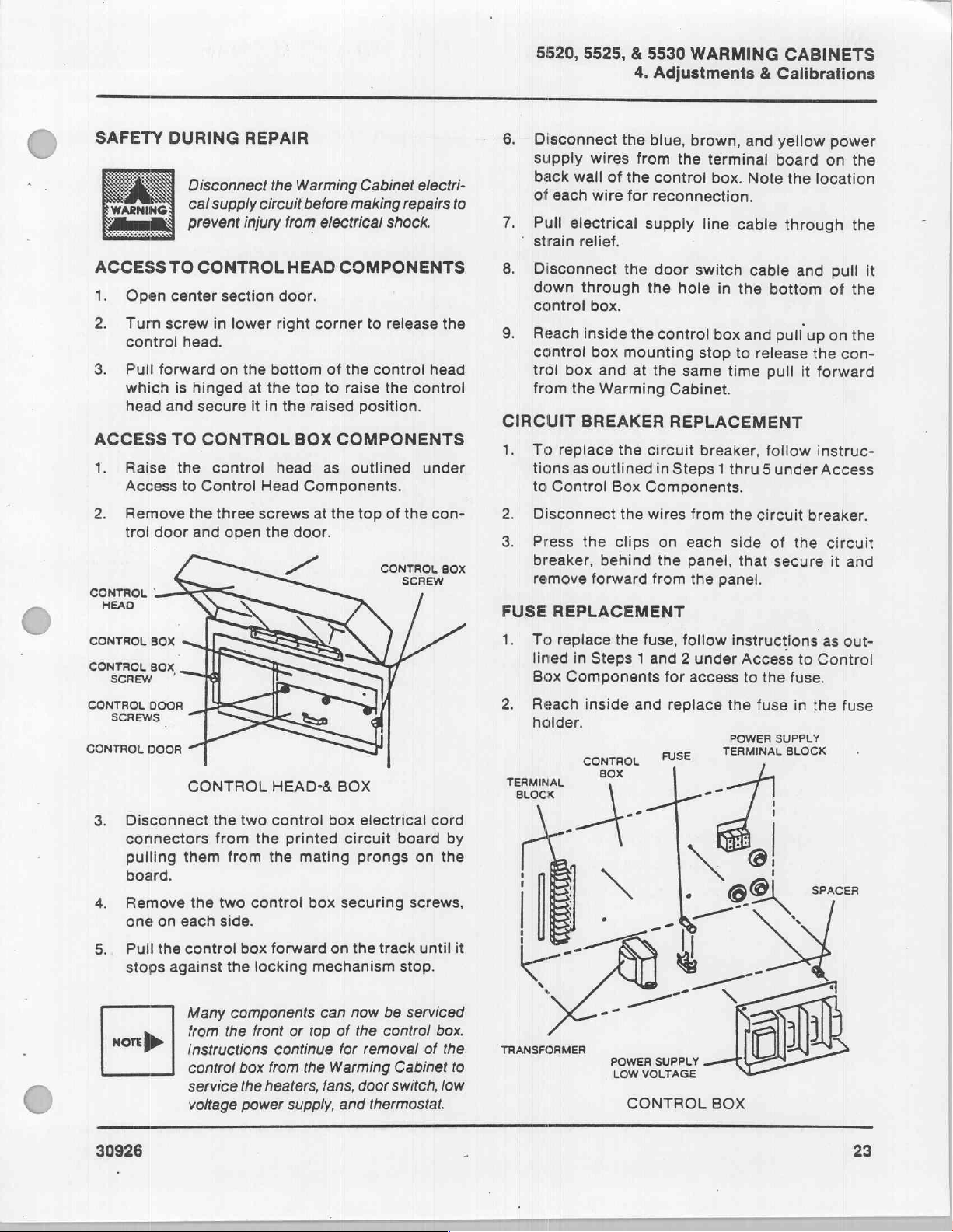
SAFETY
DURING
SV
es
ACCESS
1.
2.
3.
ACCESS
1.
2.
CONTROL
HEAD
Open
Turn
screw
control
Pull
forward
which
head
and
Raise
Access
Remove
trol
door
.
TO
center
head.
is
TO
the
to
REPAIR
Disconnect
Cal
supply
prevent
injury
CONTROL
section
in
lower
on
the
hinged
secure
at
it
CONTROL
control
Control
the
three
and
open
the
Warming
circuit
from
HEAD
door.
right
bottom
the top
in
the
BOX
head
Head
screws
the
door.
Cabinet
before
making
electrical
COMPONENTS
corner
raised
of
to
the
raise
to
control
position.
COMPONENTS
as
outlined
Components.
at
the
top
electri-
repairs
shock.
release
the
control
of
the
CONTROL
SCREW
to
the
head
under
con-
BOX
6.
Disconnect
supply
back
of
each
7.
Pull
‘
strain
8.
Disconnect
down
control
9.
Reach
control
trol
from
CIRCUIT
1.
To
tions
to
Control
2.
Disconnect
3.
Press
breaker,
remove
FUSE
REPLACEMENT
wires
wall
of
wire
electrical
relief.
through
box.
inside
box
box and
the
Warming
BREAKER
replace
the
as
outlined
Box
the
the clips on
behind
forward
the
blue,
from
the
the
control
for
reconnection.
supply
the
door
the
hole
the
control
mounting
at
the
same
Cabinet.
REPLACEMENT
circuit
in
Steps 1 thru 5 under
Components.
wires
each
the
from
brown,
terminal
box.
line
switch
in
box
stop
breaker,
from
panel,
the
panel.
and
Note
cable
cable
the
and
to
time
the
side
that
yellow
board
the
through
and
bottom
pull
release
pull
follow
circuit
of
the
secure
power
on
location
pull
of
up
on the
the
con-
it
forward
instruc-
Access
breaker.
circuit
it
the
the
it
the
and
CONTROL
CONTROL
SCREW
CONTROL
SCREWS
CONTROL
3.
Disconnect
connectors
pulling
board.
4.
Remove
one
5.
Pull
stops
мот
BOX
80x,
DOOR
L
DOOR
CONTROL
them
on
each
the
control
against
Many
from
}>
Instructions
control
service
voltage
the
from
the
two control box
side.
the
HEAD-&
two
control
the
printed
from
the
box
forward
the
locking
components
front
continue
box
from
the
heaters,
power
supply,
mating
mechanism
can
or
top
the
fans,
BOX
box
electrical
circuit
prongs
securing
on the
now
of
the
for
removal
Warming
door
and
thermostat.
board
on the
screws,
track
stop.
be
serviced
control
Cabinet
switch,
cord
by
until
box.
of
the
low
1.
2.
it
TRANSFORMER
to
To
lined
Box
Reach
holder.
TERMINAL
BLOCK
replace
Components
the
fuse,
in
Steps 1 and 2 under
inside
and
contro,
NOE
POWER
SUPPLY
LOW
VOLTAGE
CONTROL
follow
for
access
replace
FUSE
e
instructions
Access
to
the
the
fuse
POWER
TERMINAL
SUPPLY
--
O
BOX
to
Control
fuse.
in
the
BLOCK
SPACER
)
as
out-
fuse
30926
>
23
Page 29
5520, 5525, & 5530
4.
Adjustments & Calibrations
TRANSFORMER
Us
To
replace
as
outlined
Control
transformer.
Disconnect
Box
WARMING
REPLACEMENT
the
transformer,
in
Steps 1 thru 5 under
Components
.
the
wires.
Note
reassembly.
CABINETS
follow
for
access
location
instructions
Access
of
wires
to
to
the
for
FAN
REPLACEMENT
Toreplace
È
the
9
under
Disconnect
Remove
secure
Warming
Access
the
the
the
fan,
Cabinet
the
four
fan.
remove
to
Control
fan
bolts,
the
as
outlined
wiring.
nuts,
control
Box
Components.
and
box
from
in
Steps 1 thru
washers
that
Replace
bottom
and
LOW
of
washers.
VOLTAGE
REPLACEMENT
To
E
replace
trol
box
in
Steps 1 thru 9 as
Control
Remove
2A2TB
Remove
supply.
power
sembled
After
outlined
terminal
supply
replacing
Calibration.
the
transformer
the
control
POWER
the
from
the
Box
Components.
#1
wire
the
four
Retain
with
the
under
power
Warming
outlined
from
strip.
screws
the
four
and
panel
replacement
the
power
Low
which
box
with
SUPPLY
supply,
Cabinet
2A1J
that
spacers
which
supply,
Voltage
is
secured
two
remove
under
and
secure
must
power
Power
to
bolts,
the
as
outlined
Access
#4
wire
the
power
between
be
supply.
calibrate
Supply
the
nuts,
con-
to
from
the
reas-
it
as
HEATER
1.
REPLACEMENT
То
replace
from
the
1
thru 9 under
Warming
ponents.
Remove
three
Unscrew
Replace
removed.
the
screws.
the
in
THERMOSTAT
To
1.
replace
box
from
the
Steps 1 thru 9 under
Components.
Remove
Remove
standoffs,
wires
the
with
heaters,
heater
heaters
the
remove
Cabinet
Access
cover
from
exact
REPLACEMENT
the
thermostat,
Warming
from
the
thermostat
screws.
the
as
outlined
to
Control
which
location
Cabinet
Access
is
the
heater
remove
to
as
thermostat.
which
is
control box
in
Steps
Box
Com-
secured
with
sockets.
from
the
which
control
outlined
Control
secured
Box
in
to
24
30926
Page 30
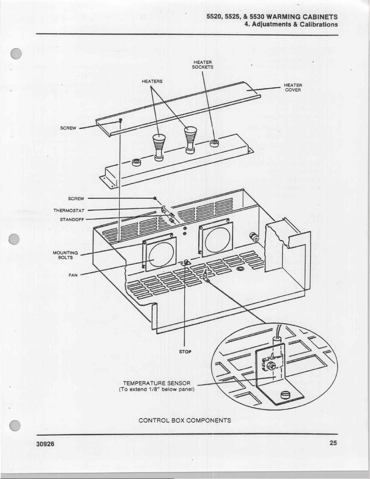
5520, 5525, & 5530
4.
HEATER
SOCKETS
WARMING
Adjustments & Calibrations
CABINETS
MOUNTING
BOLTS
РАМ
SN
|
—
TEMPERATURE
(To
extend
H
1/8“
=>
SENSOR
below
2
>
STOP
panel)
<>
==
30926
CONTROL
BOX
COMPONENTS
25
Page 31
5520, 5525, & 5530
4.
Adjustments & Calibrations
DOOR
1.
SWITCH
To
replace
box
from
the
Steps 1 thru 9 under
WARMING
REPLACEMENT
the
door
switch,
Warming
Access
Components.
2.
Remove
Press
behind
forward
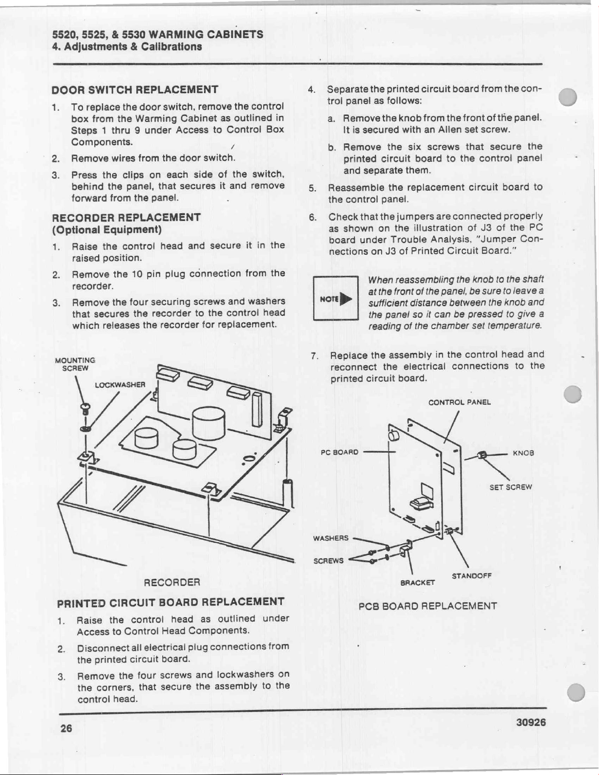
RECORDER
(Optional
1.
Raise
raised
Remove
2.
wires
from
the
clips
the
panel,
from
the
REPLACEMENT
Equipment)
the
control
position.
pin
10
the
the
on
each
that
panel.
head
plug
recorder.
securing
four
3.
Remove
that
which
the
secures
releases
the
the
recorder
recorder
CABINETS
remove
Cabinet
door
switch.
side
secures
and
connection
screws
to
the
for
the
control
as
outlined
to
Control
y
of
the
switch,
it
and
remove
secure
it
from
washers
and
control
replacement.
in
head
Box
the
the
in
4.
5.
6.
nore
Separate
trol
panel
a.
Remove
It
is
secured
b.
Remove
printed
and
separate
Reassemble
the
control
Check
as
board
nections
that
shown
under
>
the
printed
as
follows:
the
knob
with
the
six
circuit
them.
the
replacement
panel.
the
jumpers
on
the
Trouble
on
J3
of
When
reassembling
at
the
front
sufficient
the
panel
reading
of
circuit
from
board
illustration
Printed
of
distance
so
the
the
an
Allen
screws
to
are
Analysis,
Circuit
the
panel,
between
it
can
chamber
board
connected
the
be
front
set
that
the
control
circuit
of
“Jumper
knob
be
pressed
set
from
the
con-
of
the
panel.
screw.
secure
panel
board
properly
J3
of
the
Con-
Board.”
to
the
shatt
sure
to
leave
the
knob
to
give
temperature.
the
to
PC
a
and
a
MOUNTING
SCREW
PRINTED
Raise
1.
Access
Disconnectall
2.
the
Remove
3.
the
control
LOCKWASHER
CIRCUIT
the
Control
to
printed
the
corners,
head.
RECORDER
control
electrical
circuit
four
that
BOARD
head
Head
board.
screws
secure
REPLACEMENT
outlined
as
Components.
connections
plug
lockwashers
and
assembly
the
under
from
on
the
to
Replace
reconnect
printed
PC
WASHERS
재배
BOARD
=
the
assembly
the
circuit
electrical
board.
in
the
CONTROL
control
connections
PANEL
+,
SET
head
to
KNOB
SCREW
and
the
STANDOFF
30926
PCB
BRACKET
BOARD
REPLACEMENT
Page 32
5520,
5525, & 5530
WARMING
CABINETS
5.
Repair
RELAY
A
secured
nut
and
1.
Toreplace
lined
Box
2.
Note
reassembly
tions.
3.
Replace
DOOR
1.
Replacement
door.
a.
b.
REPLACEMENTS
solid
state
40
to
the
backside
screw,
Components
GASKET
Remove
door,
edge
secures
Assemble
and
screws
and a nut
the
relays,
in
Steps 1 and 2 under
the
exact
and
the
relay.
REPLACEMENT
of
the
that
secures
of
the
gasket
the
the
then
secure
that
AMP
and a 2.5
of
respectively.
follow
for
access
location
then
remove
gasket
door
plate
to
door
plate
door
gasket
both
were
removed.
the
control
instructions
Access
to
of
wire
relay
at
outer
on
the
gasket.
expose
and
to
the
AMP
relay
door
as
to
Control
the
relays.
connections
wire
connec-
perimeter
the
inside
Raise
the
screws
gasket.
to
the
door
door
with
are
with
out-
for
of
the
the
that
plate
the
a
of
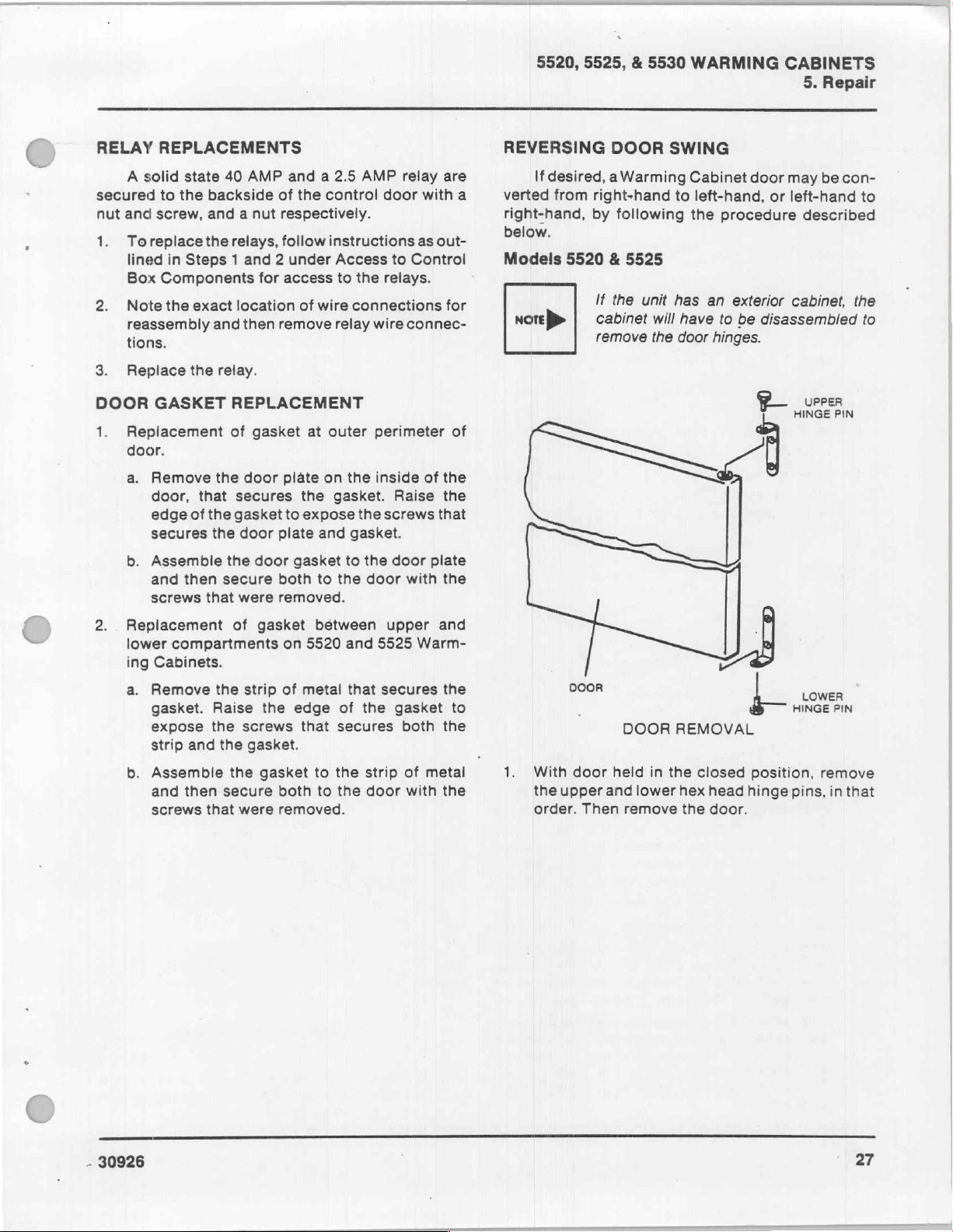
REVERSING
If
desired, a Warming
verted
right-hand,
below.
Models
ноге
}>
from
5520 & 5525
DOOR
right-hand
by
following
If
the
unit
cabinet
remove
will
the
SWING
Cabinet
to
left-hand,
the
has
an
have
door
door
procedure
exterior
to
be
disassembled
hinges.
P
may
or
left-hand
described
cabinet,
UPPER
HINGE
be
con-
to
the
to
PIN
2..
Replacement
lower
ing
a.
b.
compartments
Cabinets.
Remove
gasket.
expose
strip
Assemble
and
screws
Raise
the
and
then
that
of
the
strip
screws
the
the
secure
were
gasket
on
of
the
gasket.
gasket
both
removed.
between
5520
metal
edge
that
to
to
and
that
of
the
secures
the
strip
the
door
upper
5525
Warm-
secures
gasket
both
of
with
and
the
to
the
metal
the
1.
DOOR
With
the
upper
order.
L
door
Then
DOOR
held
in
and lower
remove
REMOVAL
the
closed
hex
head
the
door.
|
HINGE
position,
hinge
pins,
LOWER
PIN
remove
in
that
-
30926
27
Page 33

5520, 5525,
5.
Repair
2.
Remove
bracket
&
5530
WARMING
the
upper
assemblies.
and
lower
CABINETS
hinge
mounting
DOOR
А
SCREWS
&
WASHERS
STRIKER
PLATE
ASSEMBLY
SCREWS
&
WASHERS
TRIM
TRIM
3
“一 一 |
SWITCH
=
se
SWITCH
E
Е
SWITCH
E
|
—
HINGE
MOUNTING
BRACKET
SELF-TAPPING
SCREW
k
i
INSIDE
PANEL
ss
PANEL & GASKET
the
inside
Cabinet
#8-32
self-tapping
panel
door.
REMOVAL
and
It
is
secured
screws.
gasket
from
with
forty
the
>
Gi
À
WASHER-
HEAD
SCREWS
Е
HINGE
ll
MOUNTING
BRACKET
ASSEMBLY
&
GASKET
5.
Remove
Warming
five
3.
Remove
and
Warming
holes
previously
the
side
4.
Removethe
mounting
side
screws
the
Reassemble
the
had
the
viously
assembly.
28
DOOR
hinge
holes
washer-head
HARDWARE
the
two
stiffeners
Cabinet,
where
been
mounting
of
the
Warming
door
position
panel.
from
the
opposite
the
where
previously
occupied
sets
from
the
hinge
assembled.
striker
Remove
identical
Warming
door
the
been
screws
RELOCATION
of
screws,
the
opposite
and
assemble
mounting
brackets
Cabinet.
plate
on the
the
mounting
Cabinet
striker
three
washer-head
located,
by
the
In
assembly
Warming
three
plate
to
the
door
trim
side
them
brackets
turn,
assemble
to
the
washer-head
position
side
assembly
and
reassemble
position
striker
washers,
of
the
in
the
had
opposite
from
its
Cabinet
on
panel.
to
screws
pre-
plate
SPEED
6.
CLIP
Remove
speed
and
reassemble
NAMEPLATE
the
nameplate.
clips.
Rotate
to
ROTATE
ROTATION
the
the
same
180°
DOOR
It
is
secured
nameplate
holes.
180
NAMEPLATE
with
two
degrees
30926
>
Page 34

QXX
+
|
DOOR
HANDLE
a
À
SWING
180°
5520,
DOOR
o
5525, & 5530
DOOR
REMOVAL
WARMING
£
pees
CABINETS
5.
Repair
UPPER
HINGE
PIN
LOWER
HINGE
PIN
(O)
アー
Remove
located
directly
24
door
Remove
opposite
allow
reassemble
had
washer.
other end
#10-32
had
Rotate
inside
rotate
Reassemble
hex
pin
with
to
Model
nore
DOOR
the
in
below
screw
panel
the
the
previously
Tighten
screw
originally
the
door
the
head
first.
the
upper
secure
5530
If
will
>
door
HANDLE
#10-32
the
that
in
other
end
door
the
of
door
panel
panel
the
hinge
Fit
door
door
unit
have
hinges
bottom
the
door
secures
the
vicinity
#10-24
of
the
handle
unattached
held
the
the
fastener
the
door
and
trim
secured
180
degrees.
and
and
gasket.
door
pins.
Assemble
onto
hinge.
has
to
Warming
an
to
be
Assemble
exterior
to
RELOCATION
screw
to
gasket
disassembled
be
and
portion
handle.
the
door
of
screw
door
handle.
swing
end
#10-32
handle.
washer
the
door
to
to
the
the
pin
Cabinet.
cabinet,
moved.
Loosen
the
that
downward
to
screw
that
Assemble
to
handle.
Reassemble
the
hinges
the
and
upper
trim
of
the
handle
door
secures
Carefully
the
hole
and
secures
the
hole
door.
using
lower
align
hinge
the
to
allow
washer
door,
the
#10-
to
the
latch.
the
and
that
trim
the
the
that
the
Do
not
the
hinge
door
pin
cabinet
the
|
SCREWS
&TRIM
WASHERS
LATE
ASSEMBLY
SCREWS
&TRIM
WASHERS
With
door
held
in
the
closed
the
lower
and
upper
hex
order.
Remove
bracket
こつ
Then
remove
the
upper
assemblies.
な
the
and
-
—el__
Г
DOOR
SWITCH
SWITCH
HARDWARE
position,
head
hinge
door.
lower
hinge
RELOCATION
remove
pins,
in
mounting
HINGE
MOUNTING
BRACKET
ASSEMBLY
WASHER-
HERO
SE
HINGE
MOUNTING
BRACKET
ASSEMBLY
that
1
e
b
30926
29
Page 35

5520, 5525, & 5530
5.
Repair
3.
and
Warming
the
side
4.
side
screws
the
the
viously
5.
Warming
Remove
holes
previously
Removethe
mounting
Reassemble
the
had
assembly.
Remove
one
the
two
stiffeners
Cabinet,
where
hinge
of
panel.
opposite
holes
previously
washer-head
#8-32
the
been
mounting
the
Warming
door
position
Remove
from
the
the
where
occupied
the
inside
Cabinet
self-tapping
Warming
WARMING
sets
of
from
the
and
hinge
mounting
assembled.
brackets
Cabinet.
striker
on the
the
identical
door
striker
the
three
been
located,
screws
by
the
panel
door.
screws.
CABINETS
screws,
opposite
assemble
In
turn,
to
plate
assembly
Warming
three
mounting
Cabinet
plate
washer-head
and
to
the
door
and
gasket
It
is
secured
trim
washers,
side
of
them
in
brackets
assemble
the
opposite
from
Cabinet
washer-head
position
side
panel.
assembly
screws
reassemble
position
striker
from
with
plate
thirty
the
the
had
its
on
to
pre-
the
SELF-TAPPING
SCREW
i
INSIDE
PANEL
&
GASKET
PANEL & GASKET
MOUNTING
DOOR
SECURE
BOTTOM
OF
HOLES
TO
ROW
SPEED
6.
CLIP
Remove
speed
and
reassemble
NAMEPLATE
the
nameplate.
clips.
Rotate
to
ROTATE
ROTATION
the
the
same
180°
It
is
secured
nameplate
holes.
NAMEPLATE
with
180
degrees
two
Rotate
inside
rotate
tom
panel and
provided
Reassemble
hex
pin
with
to
the
door
the
row
head
first.
the
secure
upper
door
panel
panel
and
of
seif-tapping
gasket
in
the
door.
the
hinge
pins.
Fit
door
hinge.
door
to
180
degrees.
and
gasket
gasket.
to
the
door
Assemble
onto
Assemble
Warming
to
Make
fasteners
bottom
to
the
the
pin
Cabinet.
Reassemble
the
door.
sure
assemble
row
hinges
the
lower
and
upper
using
align
Do
the
of
holes
hinge
hinge
the
not
bot-
the
the
door
pin
30
30926
 Loading...