

Page 1
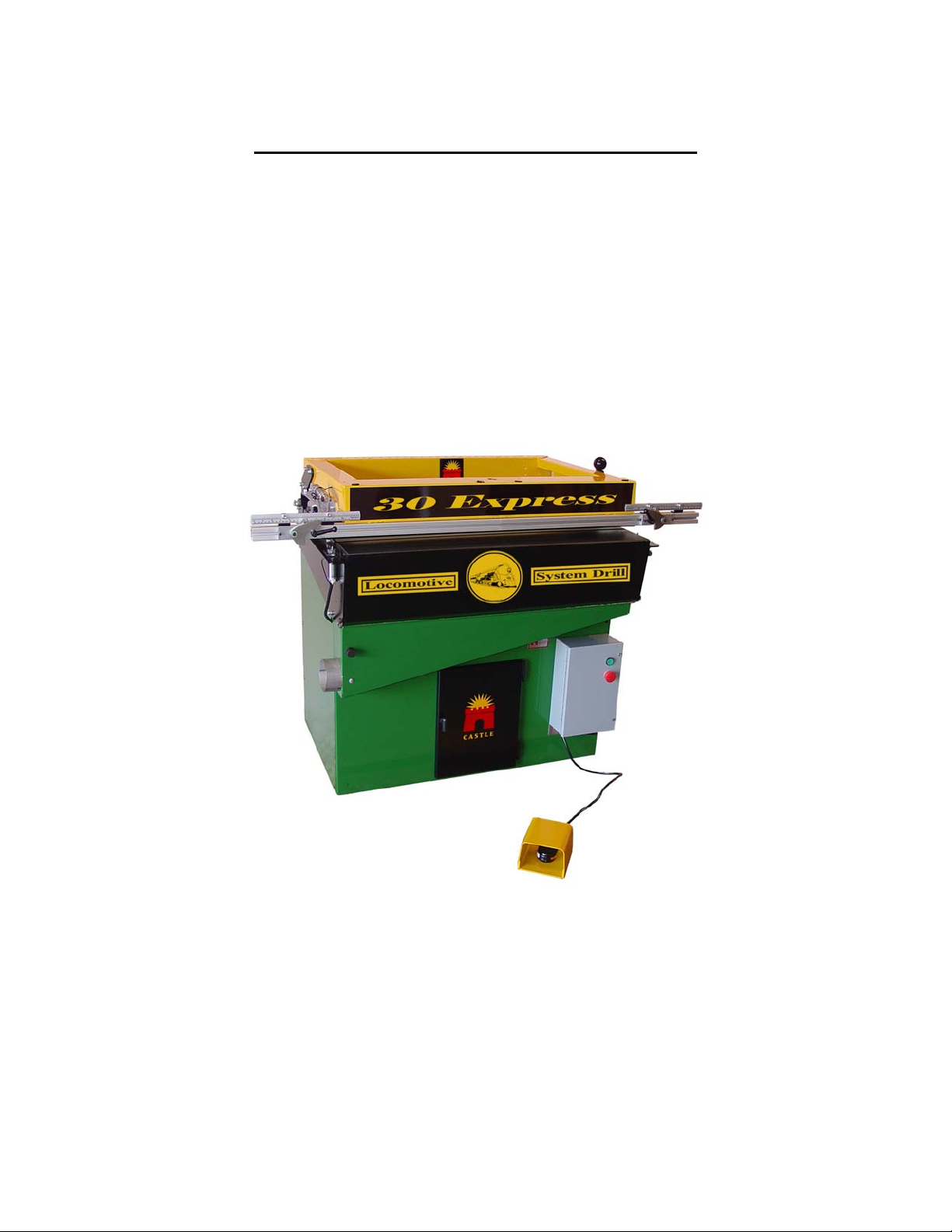
Castle System Drill
30 Express
Operator’s Manual
Castle, Inc.
Petaluma, CA
800-282-8338
Page 2

Table of Contents
Safety Notification…………………... Page 1
Machine Parts Inventory..…..………. Page 2
Machine Requirements……………… Page 2
Setting Up…………………………… Page 3-5
Operating Instructions……………… Page 6-7
Machine Adjustments………………. Page 8-11
Definition and Description of Parts… Page 12-14
Maintenance ……………………….. Page 15
Troubleshooting……………………. Page 16-17
Warranty…………………………… Page 18
Page 3
DO NOT OPERATE THIS MACHINE
UNTIL YOU HAVE READ THIS
MANUAL COMPLETELY.
Safety Notification
WARNING:
This machine was carefully prepared for shipment at
our factory. Upon receipt of this machine, inspect for
shipping damage. The Castle 30 Express System Drill
was designed with operator safety as a priority.
Report any damage immediately to the freight
company, your Castle dealer and to Castle, Inc. DO
NOT attempt to operate this machine if you observe
any physical damage.
Contact Castle, Inc. at 800-282-8338 for instructions.
1
Page 4
Inventory
d
With your Castle machine, you should have received the following:
Warranty Card (Please fill out & mail to Castle, Inc. to activate
your warranty)
30 Express Operator’s Manual
One bottle of Line Boring Oil
Left and Right Side Stop Assemblies
4” Dust Collection Port Tube
Magnetic Sheet for Dust Collection
Machine Requirements
Electricity: 220V, Single Phase
Air Supply: 80 PSI minimum, 150 PSI maximum
Never use an extension cord to
power this machine.
Use of an extension cord can
cause motor damage and may voi
your warranty
2
Page 5

Setting Up Your 30 Express
Your Castle 30 Express system drill was set up at the factory and tested for proper operation.
It is normal to find a small amount of sawdust residue in the machine as a result of this process.
Begin set up on your 30 Express by removing the Phillips head screws from each corner
of the machine that attach the machine to the pallet. Position and secure your machine
in a chosen location.
The holes on the inside base of the machine are for securing your machine to the floor,
should you wish to do so.
Supply a compressed air hose to the lower right side of the machine and connect it to the
Air Fitting.
Castle strongly recommends adding filtration to this, and any Castle machine, that uses
compressed air as part of its operation. Parker filters are available from Castle that will
extend a 5 year warranty over all Parker components used in the machine.
A ¼” female pipe thread is provided for the connection.
It is suggested that a minimum 3/8” air line be used to operate this machine. A smaller
line may slow the drilling process considerably.
Plug in your machine. A 15 Amp circuit or larger will run your new 30 Express Line
Boring Machine. DO NOT use an extension cord.
Castle recommends attaching a dust collection system. This will clear particles of dust,
as well as vent the Motor to keep it cool. Doing so will also help extend the life of the
Motor Bearings.
The Clamp Beam is found inside the machine wrapped in foam. Unwrap it and locate
the Triple T-nut. Connect the 2 pieces of aluminum extrusion so that the side stops are
facing the same direction, and are mirrors of one another. From the side of the machine,
slide the extrusion over the 4 carriage bolt heads on the underside of the Yellow Clamp
Frame. Use a ½” socket through the Clamp Frame to tighten the Clamp Beam extrusion
into place.
If dust collection is available, remove the Magnetic Strip from the inside of the machine
and attach it to the under side of the Dust Collection Chute.
To set your Side Stop Rules use a piece of scrap panel and push it up against the Side
Stop on the right side. Drill a line of holes, measure the distance from the edge of the
panel to the first hole, then set the rule to match. Repeat on the left side.
3
Page 6
Now that the tape is calibrated you are ready to drill your first test panel.
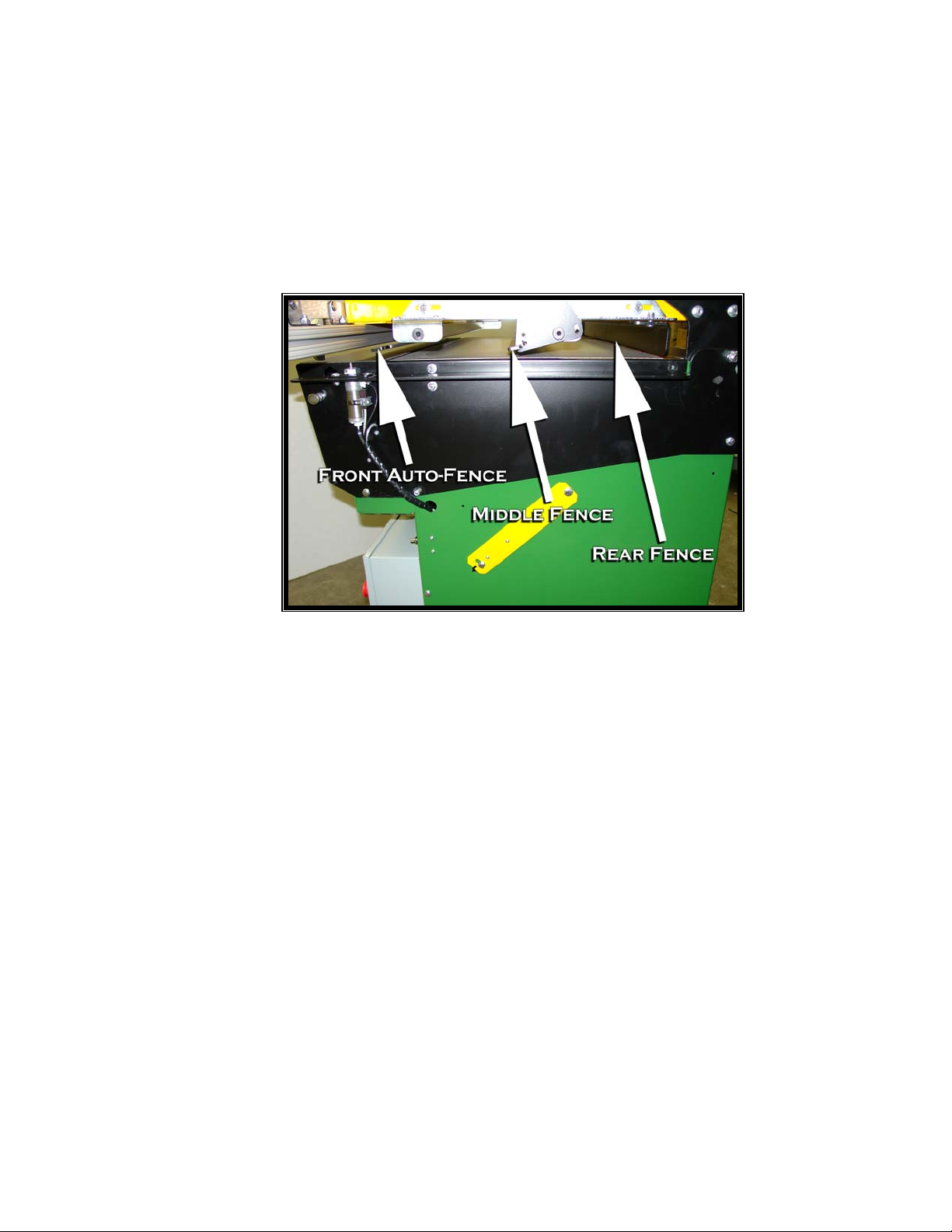
The Front Auto-Fence is factory set to 37mm from the center of the Drill Bits to
the front edge of the board.
.
Insert your first test panel under the Clamp Beam with the front edge of the panel
facing in, toward the Front Auto-Fence and the bottom edge of the panel toward
the Right Stop. If the Front Fence is up tap the Foot Pedal to toggle it down.
The panel should now be in a position for the Clamp to come down and the Drill
Bits to come up from the bottom to drill the first row of holes.
Press the green Start Button. (The red Safety Button must be pulled out to the
ready position before green button will activate your machine.)
Step on the Foot Pedal and hold it down until the drill completes the drilling cycle
(approximately 3 seconds). You may hear a released air sound after the panel has
been drilled. This is normal.
NOTE: If at any time during the clamping and drilling cycle you release the Foot
Pedal, the drilling process will be interrupted and will stop drilling. The Clamp will
release, the Auto-Fence will change position, and the drill will retract to the ready
position.
This has completed the first row of holes in the under side of your panel.
4
Page 7

Pull the Black Fence Knob toward you, dropping the Middle Fence into place.
Again, slide the panel to the right until it is pressed against the Right Stop.
Keep Your Fingers Away From the Clamping Beam.
Step on the Foot Pedal again and wait for the machine to complete its drilling
cycle.
Release the Foot Pedal.
You have just drilled the rear line of holes for a 12” panel
OR the middle row of a deeper panel.
Check to see that the holes are in satisfactory position and if necessary, make fine
adjustments to satisfy your specific line boring needs.
If you are drilling a Lower, then the Middle Fence should stay up and the panel
should be pushed all the way in to the Rear Fence.
5
Page 8

Operating Instructions
Always use eye protection when operating power equipment.
Your 30 Express was designed for boring both European type 32mm panels
and American Face Frame type cabinet construction. Since the distance
between the Bits is only critical for European style panels, your drill is using
32mm increments center to center between drill bits and will drill 5mm
diameter holes. This hole placement should not effect American style panels.
Note: Your 30 Express Line Boring Machine will shut off automatically in 2
minutes and 40 seconds if it is left running without use. Simply push the
green button to restart.
Plug your 30 Express Line Boring Machine into 220V single phase electrical
outlet. DO NOT use an extension cord!
Hook up the proper air supply and filtration. (3/8 line)
Set the Toggle Switch located on the Clamp Frame to the center or off position for
drilling standard panels.
Your machine is factory set for a cycle time of 2 ½ to 3 ½ seconds.
The Fence Drop Gauges have been factory set for Lower Panels of 24” depth and
Upper Panels of 12” depth.
the entire manual.
Always put your panels into the machine with the front edge leading into the
machine and the bottom edge indexed to the correct end of the Stop. Left Stop for
right hand panels and Right Stop for left hand panels.
Do not adjust these until you have read
Top View
6
Page 9

Drilling Panels Longer than 42” in length
If you are drilling a 96” x 12” panel for full height shelving units, use the same
procedures as you did for the 42” x 12” panel in the previous application.
Drill the first row of holes using the Right Stop. Whenever the Toggle Switch is
flipped, the first cycle will drill, then the second cycle will index.
Since the first row of holes is started from the Right Stop, you will need to flip the
Toggle Switch located in the middle of the Yellow Clamp Frame to the right to
activate the Right Side Index Pin.
Hold your left hand in the approximate position where the last hole at the left end
of the panel was just drilled.
Use your right hand to lift the Right Stop up and out of the way of the panel and
slide the panel to the right under the Yellow Clamp Frame until your left hand is
lined up with the right side of the Clamp Frame at approximately the first drill bit
location.
Step on the foot pedal and both Index Pins will try and come up to seat in a hole.
With the Toggle Switch in the right position only the right Index Pin will inform
the machine to operate.
If a hole is not in line with the pin, the machine will not cycle. This will be the
case until you move the panel slowly to the right or left slightly.
WHEN THE PIN LOCATES AN EXISTING HOLE, THE MACHINE WILL
CYCLE IMMEDIATELY AFTER THE PIN SEATS.
After you have finished with the front side of the panel, flip the Toggle Switch to
the center and then back to the right or left side to change Auto Gauge.
For 12” panel or a center row of holes pull the Black Knob toward you, dropping
the Middle Fence into working position.
Push the panel to the Middle Fence and flip the Right Stop back down into the
working position.
Press the Foot Pedal and the machine will drill the second row of holes on the back
edge (or middle) of the panel.
After drilling has finished, pop the Right Stop up and out of the way of the panel.
Slide the panel to the right until the last drilled hole is approximately even with the
last Bit and step on the foot pedal again.
Slide the panel slowly to the right or left until the Index Pin seats into the last hole
and the machine cycles. You must have your foot on the Foot Pedal through this
entire process.
Wait until the drilling is finished and then slide the panel to the right again until all
the holes you wish to drill are completed.
7
Page 10

Machine Adjustments
Removing Bits for Standard Base Cabinet Panel Drilling
If you do not want holes to run off the top of the panel when drilling standard base
cabinet panel, you can remove the additional bits or Index earlier in the panel.
To remove bits, pull the hand return plunger on the right side of the black head
cover and swing the cover down. If the Plunger seems resistant to being pulled
out, push against the cover with your hip a bit to relieve the pressure on the pin.
8
Page 11

Remove the Bits by turning the Collet counter clockwise. They require 1 ½ turns
to remove. The removed bits should be placed in their respective location holes in
the Top Rear Hole Pattern on the Yellow Clamp frame.
9
Page 12

Adjusting for Panel Width
The Auto Fence is set for 37mm from the center of the drilled 5mm hole to the
front edge of the panel. This is designed to accept European Cabinet Hardware.
(i.e., hinge plates and drawer slides.)
The Middle Fence behind the Front Auto-Fence can be adjusted forward or to the
rear, but only at 32mm increments.
The Fixed Rear Stop has additional slotted adjustments and must be set separately.
Each adjustment hole on the side is in 32mm increments from the First Fence. The
plated angle bar that the Stops are attached to is slotted for fine tune adjustments.
Using Shims
Any adjusting for depths of panel outside the 32mm steps provided for, should be
shimmed from the preset stops.
Cut the Shim piece and set the Shim in front of the second or third Panel Stop or
fence.
Put your non-standard panel in the machine as usual and drill your holes in the
positions you desire. The panel will simply bump against the Shim instead of
directly against a Fence.
10
Page 13

Hole Depth
The depth of the holes is adjustable on the right side of the machine.
Using a 7/16” wrench, loosen the Hex Head Bolt that holds the lower end of the
yellow Drill Depth Bar and insert a screwdriver into the slot. Using the
screwdriver, move the bar up or down approximately 1/8” at a time. This will
adjust the depth of drilling.
Up movement on the bar increases the depth of holes while Down decreases the
depth of the holes.
Note: Moving the bar too far up or down will trigger a micro switch and keep the
machine from cycling properly. If this happens adjust in the reverse direction
slightly and try a test piece. This is a trial and error adjustment.
11
Page 14

Description of Parts
Air Pressure Regulators
The Regulators are mounted on the back side of the Control
Box on the inside of the machine.
Bit Cover
The Bit Cover is the surface you place your work on when you
are drilling. It also opens and swings down using a Hand
Return Pluger on the side. When the Bit Cover is open you
have access to the bits and Drilling Head. NOTE: If the Bit
Cover is open the machine will NOT start.
Clamp Beam
The Clamp Beam is the aluminum extrusion mounted to the
under side of the Clamp Frame on the front of the machine.
The Clamp Beam is what comes in contact with your work to
hold it during the drilling process.
Clamp Frame
The Clamp Frame is the yellow rectangular frame on the top of
the machine. The Clamp Frame comes down to hold your work
during the drilling cycle, as well as holding the Fencing System,
all of its adjustments and the Index Pin Switch.
Drop Gauge, Automatic
The Auto-Drop Gauge replaces the manual Front Fence found
on the LB-30. The Gauge automatically raises the Front Fence
after the Setback has been drilled. It eliminates the need to
manually raise and lower the Fencing and reduces the number
of operations required to drill panel.
12
Page 15

Drop Gauge, Manual
The Middle Fence is operated by a manual Drop Gauge Lever.
This Lever drops the fence into place for drilling the second
row of holes on a standard Upper, or the middle row for a
deeper panel.
Dust Port Tube
The Dust Port Tube is mounted inside the green Dust Chute.
The Dust Port Tube is used to hook up Dust Collection to the
machine. If you are using Dust Collection, flip the Tube and
remount it so that it partially sticks out of the hole. You can
then hook the collection hose to the Dust Port Tube. If you are
not using Dust Collection then leave the tube as it is.
Dust Chute Magnet
The Dust Chute Magnet attaches to the underside of the Dust
Chute and prevents sawdust and debris from falling straight out
of the bottom of the chute. The debris will then fall along the
chute and be picked up by the Dust Collection System.
End of Cycle Switch
The End of Cycle Switch is located on the right side of the
machine mounted to a Yellow Bracket. The End of Cycle
Switch is used to let the machine know the Head has drilled
deep enough. This can be used in adjusting the drill depth of
the machine.
Flow Control
The Flow Control is located just above the Control Box on the
front of the machine. The Flow Control is what determines
how fast the Air Bag fills up to move the drill head up.
Indexing Pins
One Index Pin is located on each side of the machine. The
Index Pins are used when drilling longer panels that need more
than 30 holes. The Index Pins are activated by means of the
switch on top of the Clamp Frame.
13
Page 16

Indexing Toggle Switch
The Index Toggle is located on the top of the Clamp Frame.
When the Toggle is in the center position the Index Pins are
inactive. When the Toggle is in the left or right position, with
exception to the first cycle after switching, the machine will not
drill unless the left or right (depending if the switch is in the left
or right position) Index Pin is seated in a previously drilled
hole.
Motor Carriage
The Motor Carriage is the black frame that the Motor is
mounted to using the Spring Return Bolts and the Travel
Limiter Bolts. Do not adjust any of these settings without first
contacting Castle’s Technical Service Line.
Plunger Lock
The Plunger Lock is the mechanism that keeps the Bit Cover
from opening. It’s a simple hand operated, pull lock with a
brass head. If the Plunger seems resistant to being pulled out,
push against the cover with your hip a bit to relieve the pressure
on the pin.
14
Page 17

Maintenance
Oil the Drive System Regularly
There are two large Oil Wicks inside the Head that hold the oil and dispense it to its proper
location. If your machine begins to drip oil from the Locomotion Drive System while you are
using it, then it has been over oiled. Just wipe up the excess oil, it will not hurt your machine or
its operation and you should back off on the number of drops of oil added each 30 hours of
operation.
The Locomotive Drive System should be oiled one time per week or every 30 hours of
operation with Castle Line Boring Oil.
Open the Drill Bit Cover by pulling out on the Hand Return Plunger on the right side of
the machine and lower the Bit Cover towards you.
Inside the Bit Cover you will find an aluminum cover with holes in it. The six holes at
the top are covered with a sliding gate and the six holes across the front are not.
First, move the sliding gate to the left and drip 3 to 4 drops of Castle line boring oil into
the first hole.
Saw dust getting into these holes will not damage your machine, so don’t worry if a
little drops into the system.
Slide the Cover back over the hole and proceed to the next covered hole.
Repeat this with the other five holes on the top.
Proceed to the holes on the front side of the cover and drip 3 to 4 drops in these holes as
well.
Vacuum
Castle recommends that at least once per week you vacuum or blow the wood particles and drill
dust from around the outside of the machine and from the dust collection shoot located inside the
machine.
If using compressed air to clean the Locomotion Drive System, be careful not to blow
saw dust or wood particles into your face. Always wear eye protection when cleaning
your machine and NEVER USE HIGHLY COMPRESSED BOTTLED AIR.
15
Page 18

Troubleshooting
Do not attempt to work on the gray electrical box unless you are instructed by a
qualified Castle representative and you are a licensed electrician. This will void
your warranty.
Machine Does Not Start
Check to see that the machine has air connected to it and that the air is in the ON
position at your wall outlet.
Check to see that you are connected to the proper power supply and that you have 220V
single phase electric coming directly into the machine on a minimum 15 amp circuit.
No extension cord should ever be used with this machine. Doing so may void your
warranty.
Check to see that the Drill Bit Cover is in the fully closed position. The machine will not
start if it is not.
Be sure the Red stop button is pulled out.
Check the Thermal Overload on the Motor. Go through the Back Door of the machine
and look for the button on the side of the Motor.
Push the Green button again to see if the machine will start. If not, contact Castle, Inc.
at 800-282-8338.
The Holes are Oval Shaped After Drilling Long Panels
Several items may be out of adjustment if this happens. It is important that all your
settings be accurate to assure clean, true drilling. It is necessary to start with checking
each of the adjustments from the beginning, even if you feel they may be correct. If the
first adjustment is off, all of the others will be too.
Check the distance from the edge of the board to the edge of the holes. Be sure the
holes on the far left side are the same distance from the edge as the holes on the far right
side.
If these are all correct, skip the next step.
If not, loosen the nuts on the side that is incorrect and slightly turn the Adjustment
Screw with an Allen wrench in the direction you want to move the Drop Gauge.
16
Page 19

Remember, just a slight turn of the screw makes a lot of adjustment. 1/2 turn and THEN
test.
Drill a row of holes, holding the material so the last hole is less than 32mm away from
the end of the board.
Open the head cover and place the drilled board over the drill bits and one of the index
pins. The bits and pin should fit. Repeat on other side.
If the bits don’t line up with the index cylinder perfectly, use a 7/16” open end wrench
to loosen both nuts holding the index cylinder. Adjust the cylinder so the pin slips into
the first hole on your test block without resistance.
Tighten the bolts on each side of the index cylinder a little at a time until snug.
Do this while holding the board against the stops so there is no movement of the board,
then release the red button.
Test to see that the holes align by doing a test panel.
When correct, make the same adjustment to the left side of the machine.
17
Page 20

Warranty Information
Castle, Inc. uses only the highest quality materials available for the construction of
our machines. Your 30 Express System Drill is warranted for one full year from
the date of purchase against workmanship or material defects under normal use and
service. We are not responsible for negligence, misuse or accidents. We suggest
any and all machine maintenance or repair be discussed with an authorized Castle
Representative prior to any disassembly. We will gladly answer any questions you
may have prior to any part removal.
Castle will, at its sole discretion, either repair or replace machines that are found to
be defective. This shall be the End User’s sole remedy under this warranty.
Castle will not, under any circumstances, be liable to the End User for
consequential, incidental, special or exemplary damages, or for loss of profits,
revenue or use due to the malfunction of the machine. Further, Castle
disclaims any warranty, expressed or implied, as to the merchantability or
fitness of a Castle product for any particular purpose.
Castle, Inc. warrants the one (1) electric motor for one (1) year from date of
purchase. We suggest that you keep your receipt in a safe place. We will need a
copy for any repairs or replacements.
For Technical Assistance, Parts & Tooling:
Call 800-282-8338
Monday through Friday, 8:00am - 4:00pm, Pacific Time
Fax: 707-765-0953
18
 Loading...