

CAST Information Co., Ltd. CDVR-0404R, CDVR-1608R, CDVR-0808R Operation Manual
Operation Manual
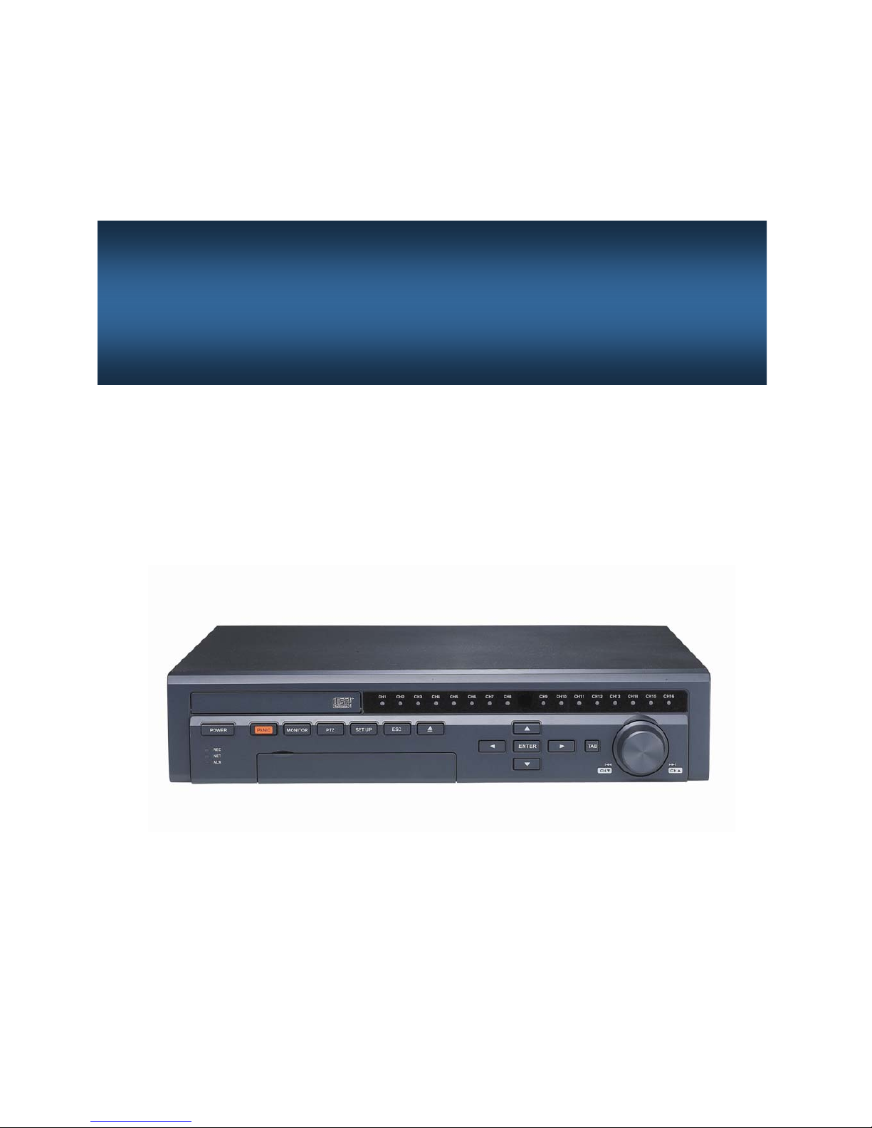
Digital Video Recorder
CDVR SERIES
2
NOTE : This equipment has been tested and found to comply with the limits for a Class A digital device,
pursuant to part 15 of the FCC Rules. These limits are designed to provide reasonable protection against
harmful interference when the equipment is operated in a commercial environment. This equipment
generates, uses, and can radiate radio frequency energy and, if not installed and used in accordance with
the instruction manual, may cause harmful interference to radio communications. Operation of this
equipment in a residential area is likely to cause harmful interference in which case the user will be
required to correct the interference at his own expense.
CAUTION : The installation of this product should be made only by qualified technicians and should
conform to all local codes.
WARNING : T o reduce a risk of fire or electrical shock, do not expose this product to r ain or moisture.
The product described in this document is in compliance with the requirements of the
European Council Directive listed below :
73/23/EEC Low Voltage Directive.
89/336/EEC EMC Directive.
This declaration is based upon compliance of the product to the following standards :
CE(LVD) EN 60065:2002
CE(EMC) EN 55022:2001 +A1:2003(Class A)
EN 50130:1995-a2+A1:1998+A2:2003
EN 61000-3-2:2000
EN 61000-3-3:1995+A1:2001
WARNING
FCC Compliance Statement

3
1. Read Instructions
All the safety and operating instructions should be read before the product is operated.
2. Retain Instruction Manuals
The safety and operating instructions should be retained for future reference.
3. Heed Warnings
All warnings on the product and in the operating instructions should be adhered to.
4. Follow Instructions
All operating and use instructions should be followed.
5. Cleaning
Unplug this product from the power outlet bef ore cleaning.
Do not use liquid cleaners or aerosol cleaners. Use a damp cloth for cleaning.
6. Attachments
Do not use attachments not recommended by the product manufacturer as they may cause hazards.
7. Water and Moisture
Do not use this product near water - for example, near a bath tub, wash bowl, kitchen sink, or laundry tub; in a wet
basement; or near a swimming pool; and the like.
8. Accessories
Do not place this product on an unstable cart, stand, tripod, brack et, or table . The prod uct may f all, ca using s erious
injury to a child or adult, and ser ious damage to the product.
9. Ventilation
Slots and openings in the cabinet are pro vided for v entil ation and t o ensure rel iable ope r ation of the product an d
to protect it from overheating, an d these openings must not be block ed or covered. The openin gs should never be
blocked by placing the product on a bed, sofa, rug, or other simil ar surface. This product shou ld not be placed in a
built-in installation such as a bookcase or rack unless proper ventilation is provided or the manufacturer’s
instructions have been a dhered to.
10. Power Sources
This product should be operated only from the type of power source indicated on the marking label. If you are not
sure of the type of power supply to your home, consult your product dealer or local power company .
11. Power-Cord Protection
Power-supply cords should be routed so that they are not likely to be walked on or pinched by items placed
upon or against them, paying particular attention to cards at plugs, convenience receptacles, and the point where
they exit from
12. Overloading
Do not overload wall outlets, extension cords, or integral con v enience receptacle as this can result in a risk of
fire or elec tric sho ck.
13. Object and Liquid Entry
Never push objects of any kind into this product through openings as they may touch dangerous voltage
points or short-out parts that could result in a fire or electric shock. Never spill liquid of an y kind on the product.
I
MPORTANT SAFETY INSTRUCTION
S

4
14. Damage Requiring Service
Unplug this product from the wall outlet and refer servicing to qualified service personnel under the following
conditions:
a) When the power-supply cord or plug is damaged.
b) If liquid has been spilled, or objects have fallen into the product.
c) If the product has been exposed to rain or water.
d) If the product does not operate normally by following the operating instructions. Adjust only those controls
that are covered by the operating instructions as an improper adjustment of other controls may result in
damage and will often require extensive work by a qualified technician to restore the product to its normal
operation.
e) If the product has been dropped or damaged in any way and
f) When the product exhibits a distinct change in performance - this indicates a need for service.
15. Replacement Parts
When replacement parts are required, be sure the service technician has used replacement parts specified by
the manufacturer or have the same characteristics as the original part. Unauthorized substitutions may result in
fire, electric shock, or other hazards.
16. Safety Check
Upon completion of any service or repairs to this product ask the service technician to perform safety checks
to determine that the product is in proper operating condition.
17. Heat
The product should be situated away from heat sources such as radiators, heat registers, stoves, or other
products (including amplifiers) that produce heat the product.
18. Internal Fan
The internal fan rotates at high speed and may cause an accident.
19. Battery
Change the lithium battery after turning off the power of the product.
Check the polarity of the lithium battery while changing and change the lithium battery with the same type
which is in the product or with a similar type recommended by your vendor.
Dispose the lithium battery according to the instructions of the battery manufacturer.
CAUTION : Risk of explosion if battery is replaced by an incorrect type.
20. Turning On/Off the DVR power.
Do not turn off the power by removal of the power plug.
T o turn off the power, click the power button from the front panel.
When the system stops abnormally , the power button might not work.
Click power button for 5 full seconds to turn power off.
Do not turn off the power improperly or apply shock/vibration to unit while the hard disk is activating.
It may cause hard disk failure or loss of data.
Important Safety Instruction
s

5
1. INTRODUCTION
1.1. DVR Components……………………........
1.2. Product Description…………….………….
1.2.1. Front Panel…………………………….
1.2.2. Rear Panel………………………….….
1.2.3. Remote Controller…………………….
2. INSTALLATION
2.1. Installation of Hard Drives……….….…….
2.2. Starting the DVR………………..………….
2.3. Log In & Log Out……..……………………….
2.4. CD Booting……………………………………
2.5. USB Flash Drive…………...………………….
3. SETUP
3.1 Setup Menu…….……....................……….
3.2. System Setup…………………………..….
3.3. Camera Setup………………………….……
3.4. Event Setup…………………………….….
3.5. Network Setup……………………..……….
3.6. Record Setup……… ………………..………
3.7. Record Scheduler………………..………….
3.8. Display Setup…………………………….….
3.9. Device Setup & Information…..…….…….
3.10. Log List……………..……………………….
3.11. Backup…………… …….………………….
4. OPERATION
4.1. Monitoring……………………………..….
4.1.1. Multi-Screen Display…………………….
4.1.2. Changing Channel…………………….
4.1.3. Freeze Screen………………….…….
4.1.4. Full Screen Display…………………….
4.2. Monitoring Control……………………….
4.2.1. Multi-ScreenDisplay…………….….
4.2.2. Video…………………………..…….
4.2.3. Audio……………………………..….
4.2.4. etc………………………………..…..
4.3. Playback (Search) ……………………….
4.3.1. Time/Date Search…………………….
4.3.2. Event Search…
………….……….…
4.3.3. File Search……………………....….
4.3.4. Capture…………………………..….
Image Capture……………..………
Video Clip Copy………………..……
4.4. PTZ Control………………………….……….
4.5. Recording……………………………..…..….
Panic Recording………………………
5. MINI PLAYER
Appendix A. Technical Specification
Appendix B. Trouble Shooting
6
7 7 8 12
13
15
16
17
17
18
20
22
24
26
29 31 32 34 35 36
37
37 37 37 38 39 39 40 40 41 43 43 47 48
49
49
49
51 53 53 54 57 58
I
NDEX
6
1.1. DVR Components
Check the package and contents for visible damage. If any components are damaged or missing, do not attempt
to use the unit, contact the supplier immediately. If the unit must be returned, it must be shipped in the original
packing box.
Remote Controller
Operation Manual
Mouse
Power Cable
CMS Program
1. I
NTRODUCTION
Digital Video Recorder
Rack Mount Bracket (2pcs).
Size AAA Batteries(2pcs).
Hard Drive Screws(12pcs).

7
1.2. Product Description
1.2.1. Front Panel
1. DVD-RW Tray Door : Insert CD or DVD disk.
2. Channel Indicator : Indicates which cameras are ope rating.
3. Press to turn on/off power. The power indicator will light up when pow er is on.
4. REC Indicator : The indicator will blink during recording.
NT Indicator : The indicator will light up during network connection.
AR Indicator : The indicator will light up when an event is triggered.
5. T oggle to start/stop panic rec ording of all channels with high recording qualit y .
6. Display the Monitoring Control Menu on the screen.
7. Enter the PTZ control mode.
8. Enter the Setup Mode.
9. Clear the Monitoring Control Menu.
Return to a higher Cate gory/Group/Field.
Cancel the selected Field button.
10. Insert and Eject CD. Y ou may also push the tray to insert the tray .
11. Operation Keys :
Activate a function or complete an entry that you hav e made during setup.
Display the Monitoring Control Menu on the screen.
Move between categories and change fie ld values.
12. TAB Move between menu groups or change the multi-screen display type.
13. JOG Dial : Change channels during monitoring.
Frame by frame reverse/forward during Playback pause mode.
14. USB Port : Connection for 2.0USB storage devices.(USB2.0 Flash Drive, CD-RW, HDD)
15. MOUSE Port : Connection for PS2 mouse.
Introduction
③ ④
②
⑤ ⑥ ⑦ ⑧ ⑨
⑪⑩
⑫ ⑬⑭
①
⑮
8
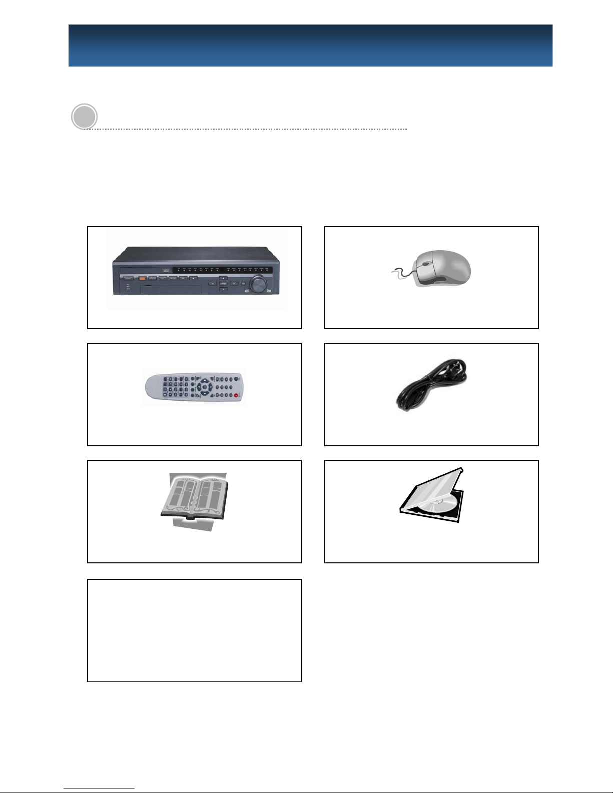
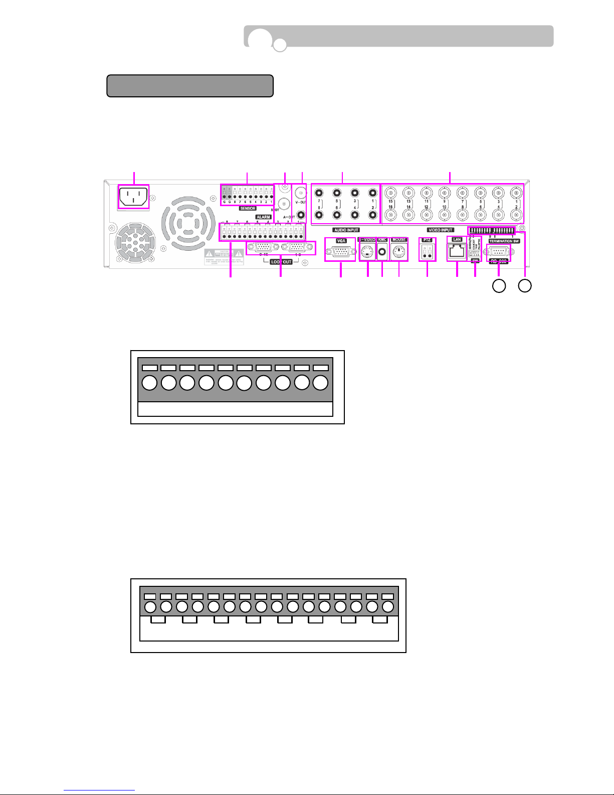
1.2.2. Rear Panel
1. POWER Socket :
Select the power of your region.( 110V or 220V).
2. VGA(Monitor) Port
- Connection to PC monitor.
3. S-VIDEO Connector
- Connection to S-Video jack.
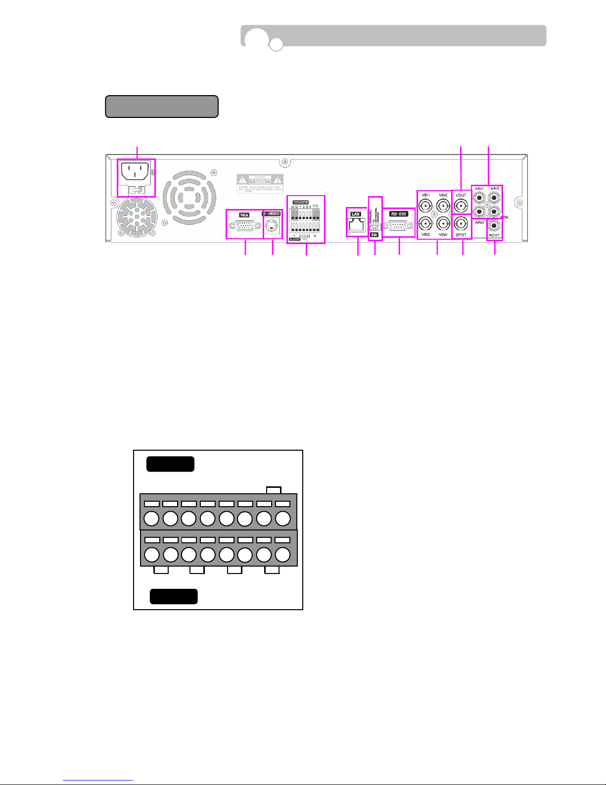
4. SENSOR/ALARM/PTZ Terminal
- Connect G(Ground) before connecting the sensors.
- Connect the alarm devices in its corresponding numbers.
- Connect the PTZ(Speed Dome Camera).
5. LAN Port
- 10/100 Base-T RJ45 et hernet port for network connection.
Introduction
CDV
R
-
0404R
1 2 3 4
SENSOR
ALARM
PTZ
G G 1 2 3 4
-
+
①
② ③④ ⑤ ⑥ ⑦ ⑧ ⑨ ⑩ ⑪⑫

9
6. SW(DIP Switch)
- Adjust the Dip Switch setting according to requi red functions. The system must be resta rted after
adjustments.
Functions OFF Position(Up) ON Position(Down)
Monitor Output VGA/PAL Composite 60Hz VGA/PAL Composite 50Hz
CD Boot Off CD Boot
Test Off Factory Test Mode
Color System NTSC PAL
* When using Composite or S-Video out put, the DVR will auto detect the output when the DVR is
Turned on.
* When changing the Monitor Output from Composite to S- Video or vice versa while the DVR is in
operation, press the Monitor button on the front pane l once
* If both Composite and S-Video output is connected, priority will be given to S-Video.
7. RS-232 Port
- Serial port for Keyboard Contro ller and POS interface.
8. VIN1~VIN4 : Video Input Connectors
- Input connectors for video signals.
9. VOUT Connector
- Output connector for Composite video output.
10. SPOT Connector
- Output connector for Spot monitor .
11. AIN1~AIN4 : Audio Input Connectors
- Input connectors for audio signals.
12. AOUT Connector
- Output connector for audio signals.
Introduction
PIN No. Explanation
PIN No. Explanation
2 RX 5 GND
3 TX 4,6,7,8 Not used
1, 9 T est
5
4 3 2 1
9
8
7
6
10
The only difference between
CDVR-0808R & CDVR-1608R is the number of Video Inputs (⑥) and
Video Loop (
⑧).
1. AC POWER Socket : Supports 110V ~ 220V free v oltage.
2. SENSOR Terminal
* Connect G(Ground) before connecting the sensors.
3. SPOT OUT Connector
- Output connector for Spot Out signal to monitor .
4. VOUT & AOUT Connectors
- Output connector for video(VOUT) and audio(AOUT) signal s.
5. AUDIO INPUT Connectors
- Input connectors for audio signals.
6. VIDEO INPUT Connectors
- Input connectors for video signals.
7. ALARM Output Terminal
- Connect the alarm devices in its corresponding numbers.
8. LOOP OUT
- T erminati on switch must be turned on when using loo p out.
9. VGA(Monitor) Port
- Connection to PC monitor.
G G 8 7 6 5 4 3 2 1
8 7 6 5 4 3 2 1
Introduction
CDVR
-
0808R/1608R
①
②
③
④
⑤
⑥
⑮ ⑦
⑧
⑨ ⑩
⑫⑬ ⑭ ⑪
1716

11
10. S-VIDEO Connector
- Connection to S-Video jack.
11. RMC Connector
- Connection to remote controller IR Receiver.
12. MOUSE Port
- Connection to PS2 Mouse.
13. PTZ Connector(RS485)
- Connection to PTZ camera.
14. LAN Port
- 10/100 Base-T RJ45 et hernet port for network connection.
15. SW(DIP Switch)
- Adjust the Dip Switch setting according to requi red functions. The system must be resta rted after
adjustments.
Functions OFF Position(Up) ON Position(Down)
Monitor Output VGA/PAL Composite 60Hz VGA/PAL Composite 50Hz
CD Boot Off CD Boot
Test Off Factory Test Mode
Color System NTSC PAL
* When using Composite or S-Video out put, the DVR will auto detect the output when the DVR is
Turned on.
* When changing the Monitor Output from Composite to S- Video or vice versa while the DVR is in
operation, press the Monitor button on the front pane l once
* If both Composite and S-Video output is connected, priority will be given to S-Video.
16. RS-232 Port
- Serial port for Keyboard Contro ller and POS interface.
17. 75 Ohm Termination SW
- T ermination Switch should be switched to the OFF(down wards) position when using Video Loop .
Introduction
PIN No. Explanation
PIN No. Explanation
2 RX 5 GND
3 TX 1,4,6,7,8,9 Not used
5
4
3
2
1
9
8
7
6
12
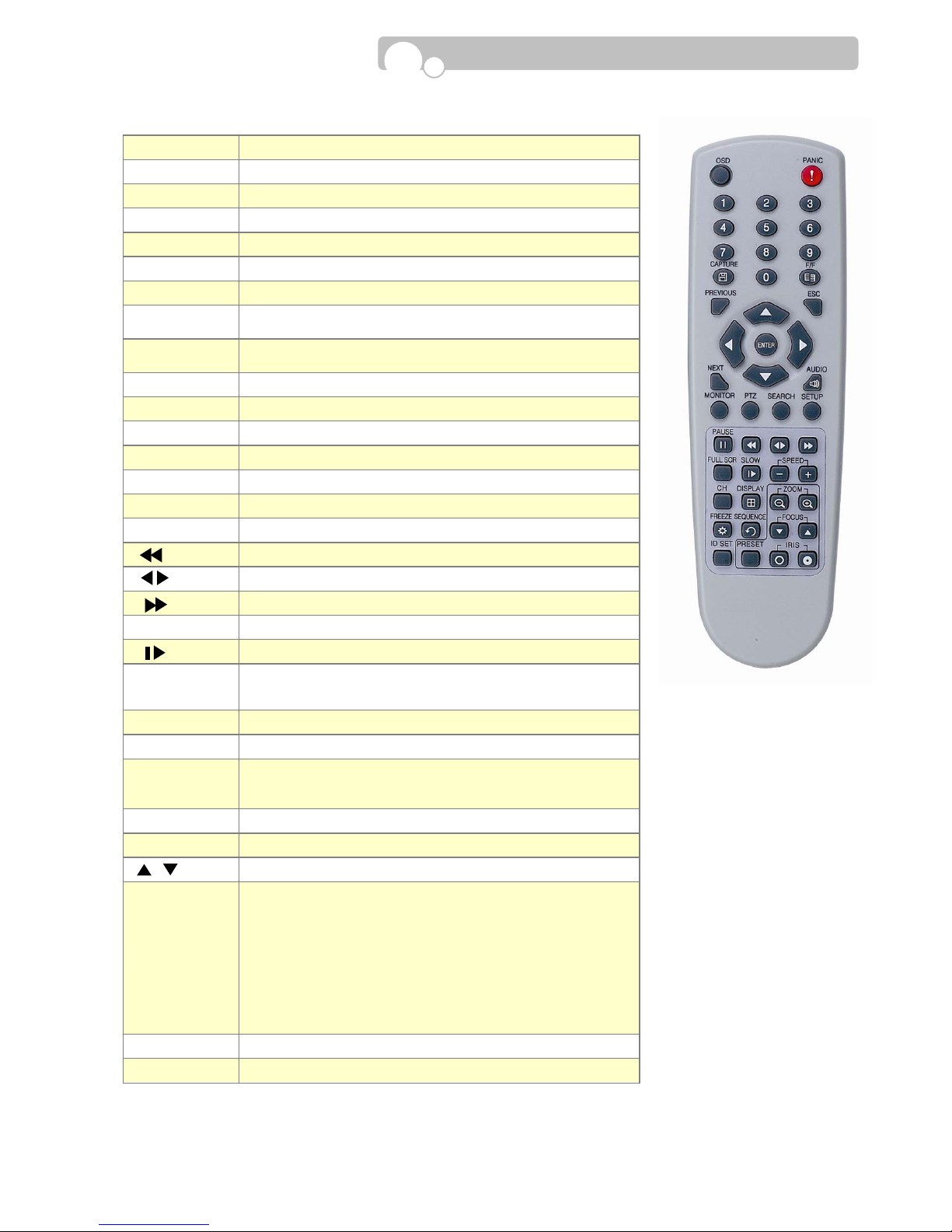
1.2.3. Remote Controller
Introduction
OSD OSD On/Off during Monitoring and Playback.
PANIC Panic Recording On/Off.
Numeral Keys Input numbers during Login/Setup/PTZ.
CAPTURE Enter video clip/image copy menu during playback.
F/F Remov e image distortion during pause.
PREVIOUS Move to previous category .
NEXT Move to next category .
Direction Keys
Move cursor left/right/up/down.
PTZ control
ENTER
Display the menu during monitoring, playback.
Select/Enable a highlighted category/function.
ESC Stop current operation or return to previous mode.
AUDIO Audio On/Off .
MONITOR Enter Monitoring mode.
PTZ Enter PTZ camera control mode.
SEARCH Enter Search(Playback) mode.
SETUP Enter Setup mode.
PAUSE Pause during playback.
Fast reverse playback
Playback in reverse/forward direction
Fast forward play back.
FULL SCR Change to full screen display during Playback.
Playback in slow motion(1/2x→1/4→1/8x→1/16)
-/+ SPEED
Increase/Decrease speed during playback.
CH Change channels during M onitoring/PTZ Control/Playback.
DISPLAY Change multi-screen display type
-/+ ZOOM
Adjust zoom of PTZ camera.
T oggle between zoom 2x and normal v iew during
monitoring.
FREEZE Freeze screen during monitoring
SEQUENCE Automatic sequence display during monitoring.
/ FOCUS Adjust focus of PTZ camera
ID Set
Set ID of remote controller.
Same ID must be applied for the DVR and remote
controller.
☞ Press the ID SET button and input the ID using the
numeral keys.
The ID must be set in 3 digits.(If DVR ID is “1” press
“001”)
The ID SET button must remain pressed while
inputting the ID.
PRESET Enter preset controls of PTZ camera
IRIS
Adjust aperture of PTZ camera.
13
2.1. Installation of Hard Disk Drives
2.1.1. Installation Order : Model CDVR-0404R
Maximum of 2 Hard Disk Drives may be installed in the DVR.
Unscrew the HDD Bracket from the DVR bottom in order to install Hard Drives.
Insert the HDD(Bottom side up) into the bracket and secure the HDD onto the bracket using 4
screws and connect the Power Plug and E-IDE Cable into the HDD connectors.
※ Adjust the Jumper Pin of the HDD to the Master or Slave position before installing the HDD.
- Fasten 2 screws on e ach side of the HDD bracket to fix the br acket to the DVR bottom.
2. I
NSTALLATION
※ Compatible Hard Disk Drives : Samsung, Maxtor , Fujitsu, Seagate, Hitachi.
※ Western Digital hard disk drives are NOT compatible with the DVR.
Power Cable
Bracket Screw
E-IDE Cable
HDD Bracket
Bracket Screw
Bracket Scre
w

14
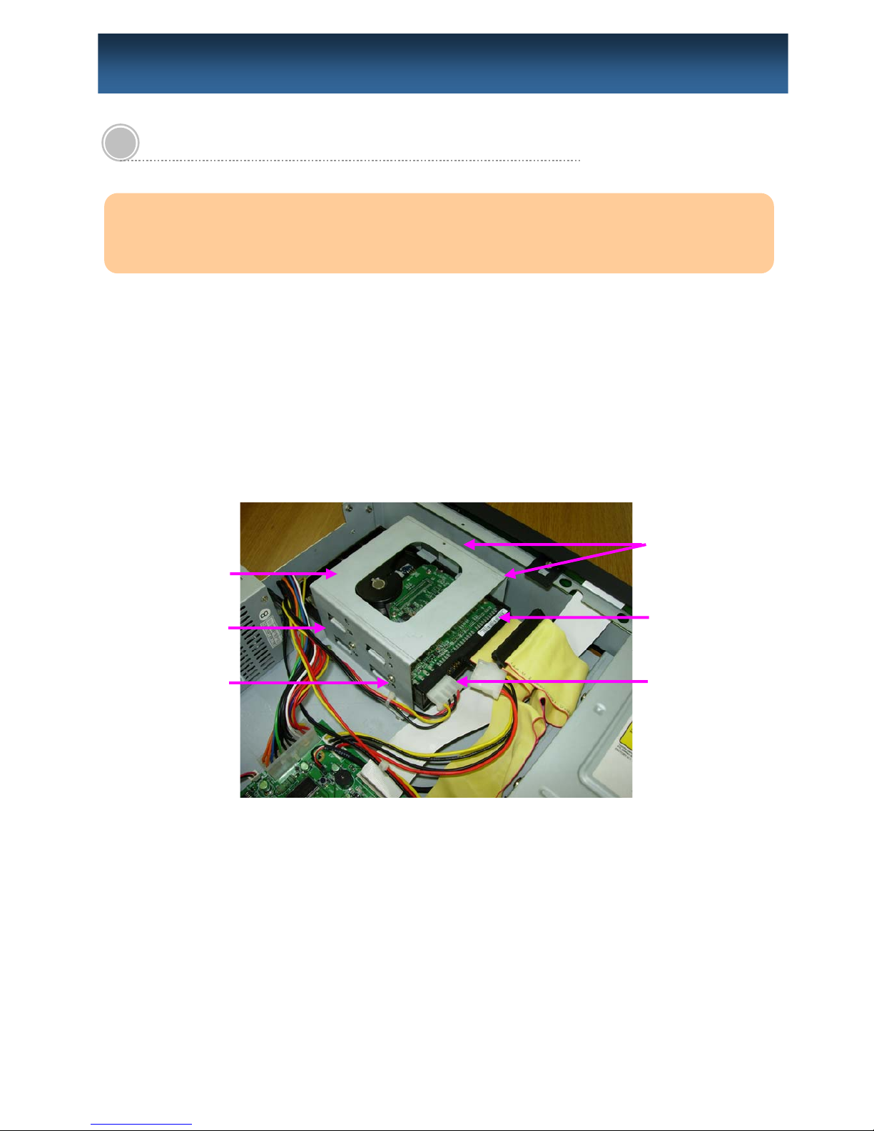
2.1.2. Installation Order : Model CDVR-0808R & CDVR-1608R
Unscrew the Brackets from the DVR bottom in order to install Hard Drives.
- Installing one HDD : PRIMARY MASTER
- Installing two HDD : PRIMARY MASTER → SECONDARY MASTER
- Installing three HDD : PRIMARY MASTER → SECONDARY MASTER → PRIMARY SLAVE
* Hard Drives must be installed in the DVR according to the above order and adjust the Jumper
Pin of the Hard Drive to the Master or Slave position.
- Fasten 2 screws on e ach side of the HDD bracket to fix the Hard Drives to the bracket.
- Fasten 2 screws on e ach side of the HDD bracket to fix the br acket to the DVR bottom.
Cable Connection.
Connect the Power Cable and E-IDE Cable to each Hard Drive.
The DVD-RW must be connected with the Secondary Slave E- IDE Cable and P ower Cable.
Primary Slave
(Above)
Primary Master
(Below)
Secondary Master
(Below)
E-IDE Cabl
e
Power Cable
DVR FRON
T
Bracket 1
Bracket 2
Screw 1
Screw 2
Screw 3
Screw 4
DVD-RW Driv
e
E-IDE Cable(Secondary)
Installation

15
2.2. Starting the DVR
After installing the hard disk, set the DIP switch to the NTSC or PAL position to match your equipment
before turning on the power of the DVR.
Then, connect the power cord and press the power button until the LED lights up to start the DVR.
When starting the DVR for the first time, formatting of the hard disk will commence automatically and the
DVR will be initialized as follows.
The DVR will perform “S.M.A.R.T.” check of the installed hard disk.
If no problem is detected [S.M.A.R.T. PASS] will be indicated and if a problem is detected [S.M.A.R.T.
FAILURE] will be indicated and a warning will appear on the monitoring screen.
The hard disk capacity indicated may be smaller than the capacity declare d by the hard disk producer. This
difference may occur due to the difference in measure units and therefore is not a defect.
If the hard disk detected has not been formatted, recording will start after the formatting is completed.
Installation
※ S.M.A.R.T. (Self Monitoring, Analysis and Reporting Technology)
S.M.A.R.T. is a reliability prediction technology to anticipate the failure of a hard disk drive with
sufficient notice to allow a system or user to back up data prior to a drive’s failure.
If the controller detects problems in the disk drive reliability, it wi ll release a warning to the
user. In such a case, the use of the disk drive should be stopped immediately and have it
examined.
※ Cautions & Warnings
1. Press the Power button on the DVR until the Power Indicator lights up.
2. The Hard Disk used in this DVR is compatible with the Windows OS by using the FA T32 file
system. However, we cannot guarantee safety against the possibility that the system may
crash with vaccine programs such as Anti-Virus, V3, etc.
3. If the Hard Disk is formatted in the Windows environment, it should be performed in
Windows XP or a higher edition and must use the FA T32 format.
4. Do not remove devices during backup or playback of recorded data. It may cause DVR
malfunctions.

16
2.3. Log In & Log Out
1. Select USER
Using
buttons, select the USER. (ADMIN, USER1
~USER5)
2. Enter the PASSWORD
A Key Panel will appear automatically when the LOGIN screen
pops up.
Enter the Password using the Key P anel and click
the button.
3. LOG OUT
Click the mouse right button or mo ve the cursor to the bottom of the screen t o bring up the Menu
bar on to the monitoring screen.
Click the mouse left button on the button on the right hand corner of the Menu Bar to escape from the
Administrator Mode.
This will prohibit any other users other than the authorized personnel with proper password to enter
PLAY(Search), PTZ Control, and SETUP
Menu Bar
Installation
※ Default value of the Password is set at “0000”.
※ Password can be changed in the SYSTEM SETUP menu.
Ke
y
Panel
※ The DVR will log out automatically if there is no oper ation for 5 minutes after entering Setup.

17
2.4. CD Booting
When you face problems with the DVR program or want to re-install or upgrade the firmw are without
entering the DVR Setup menu please take the following steps.
1. Adjust the DIP Switch located in the rear panel of the DVR to the CD Boot position(Down) and turn
on the DVR power.
2. Insert the CD containing the DVR Firmware. The name of the Firmware is “DVRSYS” and in
this directory , the following folders must exist.
- CDVR BMP
- FONT
- FW
3. Firmware installation will proceed automatically once the Firmware CD is inserted. The CD
will eject automatically once the installation is completed.
4. T ak e out the CD and adjust the DIP Switch(CD Switch) to the Off position(Up). The DVR will
automatically re-boot.
5. Repeat the above procedure if the DVR fails to re-boot.
2.5. USB Flash Drive
• This DVR supports Hi-Speed USB 2.0 Flash Drives.
- Use of Full Speed USB 2.0 Flash Drives may result in slow backup speed or capture speed.
•
Please note that the USB must be formatted using the DVR Formatting function.
- Please follow the formatting inst ructions provided in SETUP – DEVICE in page33.
• The USB port supports ex ternal USB Flash Drive, CD-RW, DVD-R and HDD
Installation
18
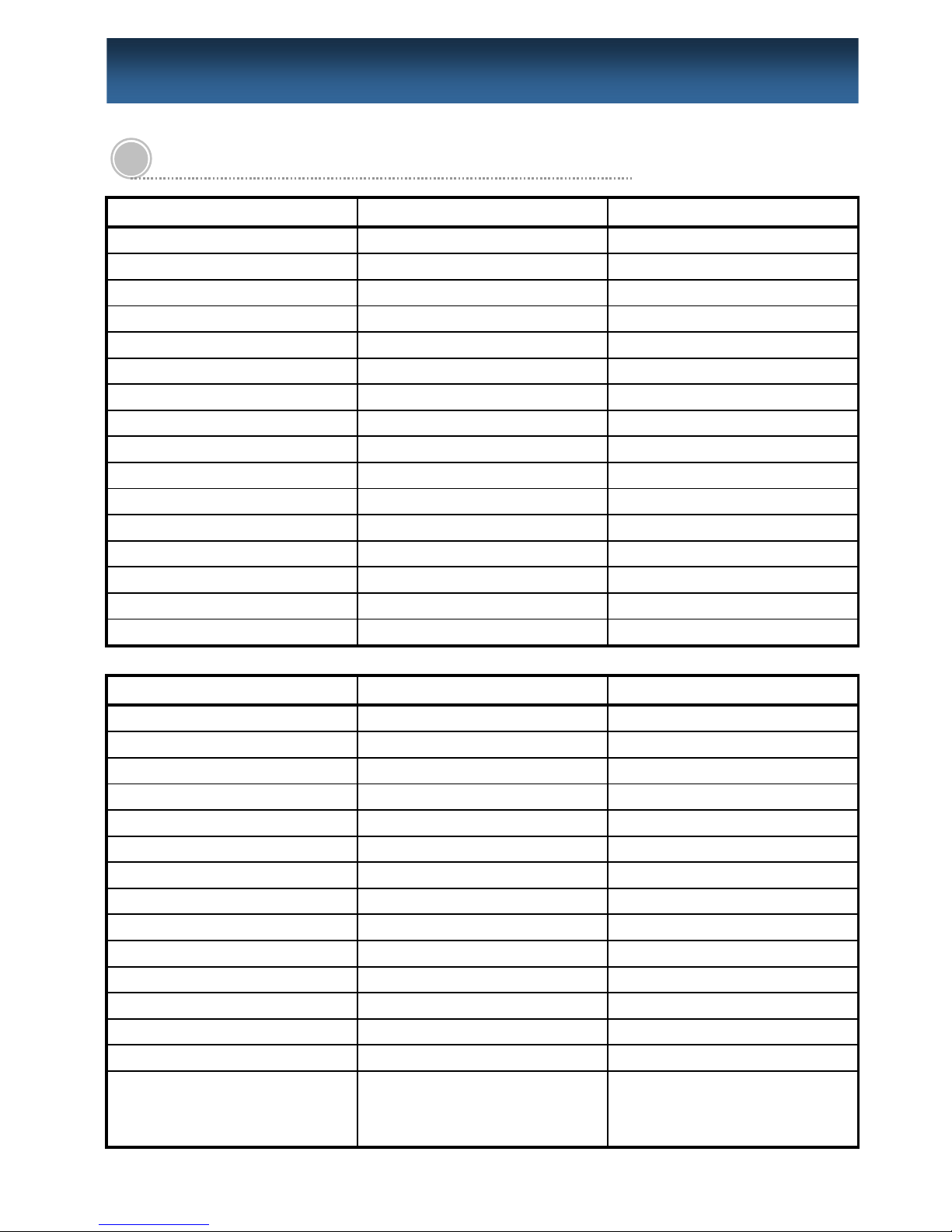
3.1. Configuration Menu
SYSTEM CAMERA EVENT
LANGUAGE CAMERA SENSOR
ID(DVR) NAME CAMERA LINK
DATE TYPE MOTION DETECTION ALARM LINK
TIME DATE SENSITIVITY(CAMERA) OPERATION TIME
DST COVERT TYPE
DST START COLOR SETTING FULL SCREEN MODE
DST END BRIGHTNESS OUTPUT DWELL TIME(ALARM)
ADMIN PASSWORD CONTRAST
USER NAME HUE CAMERA(MOTION DETECTION)
USER PASSWORD PTZ/SERIAL SETTING ALARM LINK
USER AUTHORITY ID OPERATION TIME
COLOR SYSTEM(NTSC/PAL) DRIVER FULL SCREEN MODE
S/W VERSION BAUD RATE OUTPUT DWELL TIME(ALARM)
UPGRADE(SETUP, F/W , BMP) DATA BIT
FACT ORY DEFA UL T(RESET) PARITY
STOP BIT
NETWORK RECORD SCHEDULER
IP TYPE RESOLUTION SCHEDULE
PORT/WEB PORT WA TERMARK SETUP CONTINUOUS
IP ADDRESS RECORD TIME ST AMP MOTION
GATEWAY AUDIO RECORD MOTION+SENSOR
SUBNET MASK QUICK RECORD SETUP SENSOR
DNS SERVER FPS(RECORDING SPEED) NONE
SMTP SERVER QUALITY COPY SCHEDULE
MAC ADDRESS PRE-RECORDING(EVENT)
E-MAIL SERVER ID POST -RECORDING(EVENT)
E-MAIL SERVER PASSWORD
E-MAIL SENDER
E-MAIL RECEIVER
PPPOE ID
PPPOE PASSWORD
DVR NAME
EVENT MAIL
BANDWIDTH
(Continued)
3. C
ONFIGURATION
 Loading...