

Casti CAX-01, CAX-03, CAX-04 User Manual
CAX-01/CAX-03/CAX-04
CAX-01/CAX-03/CAX-04
Please, read this user manual prior to using this product for the first time.
Call for help…Toll Free Number
1☎ -877-685-8443
Website www.casticonverter.com
Digital to Analog Converter Box
user manual
CAX-01/CAX-03/CAX-04 2
CAUTION: TO REDUCE THE RISK OF ELECTRIC SHOCK, DO NOT REMOVE COVER (OR BACK).
NO USER SERVICEABLE PARTS INSIDE. REFER TO QUALIFIED SERVICE PERSONNEL.
WARNING
TO PREVENT FIRE OR SHOCK HAZARDS, DO NOT EXPOSE THIS PRODUCT TO RAIN OR MOISTURE.
Apparatus should not be exposed to dripping or splashing and no object filled with liquids, such as vases, shall
be placed on the apparatus.
WARNING: Do not install this equipment in a confined space such as a bookcase or similar unit.
CAUTION: TO PREVENT ELECTRIC SHOCK, MATCH WIDE BLADE OF PLUG TO WIDE SLOT AND FULLY INSERT
ATTENTION: POUR ÉVITER LES CHOC ÉLECTRIQUES, INTRODUIRE LA LAME LA PLUS LARGE DE LA FICHE
DANS LABORNE CORRESPONDANTE DE LA PRISE ET POUSSER JUSQU’AU FOND.
Where the main plug or an appliance coupler is used as the disconnect device, the disconnect device
shall remain readily operable.
The Marking Information is attached on the bottom of this product.
CAUTION: Any changes or modification in construction of this device which are not expressly approved by the
party responsible for compliance could void the user's authority to operate the equipment.
REGULATORY INFORMATION: FCC Part 15
This product has been tested and found to comply with the limits for a Class B digital device, pursuant to Part
15 of the FCC Rules. These limits are designed to provide reasonable protection against harmful interference
when the product is operated in a residential installation. This product generates, uses and can radiate radio
frequency energy and, if not installed and used in accordance with the instruction manual, may cause harmful
interference to radio communications. However, there is no guarantee that interference will not occur in a
particular installation. If this product does cause harmful interference to radio or television reception, which can
be determined by turning the product off and on, the user is encouraged to try to correct the interference by
one or more of the following measures:
• Reorient or relocate the receiving antenna.
• Increase the separation between the product and receiver.
• Connect the product into an outlet on a circuit different from that to which the receiver is connected.
• Consult the dealer or an experienced radio/TV technician for help.
THE LIGHTNING FLASH WITH ARROWHEAD SYMBOL, WITHIN AN EQUILATERAL TRIANGLE,
IS INTENDED TO ALERT THE USER TO THE PRESENCE OF UNINSULATED “DANGEROUS
VOLTAGE” WITHIN THE PRODUCT’S ENCLOSURE THAT MAY BE OF SUFFICIENT
MAGNITUDE TO CONSTITUTE A RISK OF ELECTRIC SHOCK TO PERSONS.
THE EXCLAMATION POINT WITHIN AN EQUILATERAL TRIANGLE IS INTENDED TO ALERT
THE USER TO THE PRESENCE OF IMPORTANT OPERATING AND MAINTENANCE
(SERVICING) INSTRUCTIONS IN THE LITERATURE ACCOMPANYING THE APPLIANCE.
S
AFETY PRECAUTIONS

3 CAX-01/CAX-03/CAX-04
1. Read these instructions.
2. Keep these instructions.
3. Heed all warnings.
4. Follow all instructions.
5. Do not use this apparatus near water.
6. Clean only with dry cloth.
7. Do not block any ventilation openings. Install in accordance with the manufacturer’s instructions.
8. Do not install near any heat sources such as radiators, heat registers, stoves, or other apparatus (including
amplifiers) that produce heat.
9. Do not defeat the safety purpose of the polarized or grounding-type plug. A polarized plug has two blades
with one wider than the other. A grounding type plug has two blades and a third grounding prong. The wide
blade or the third prong are provided for your safety. If the provided plug does not fit into your outlet, consult
an electrician for replacement of the obsolete outlet.
10. Protect the power cord from being walked on or pinched particularly at plugs, convenience receptacles, and
the point where they exit from the apparatus.
11. Only use attachments/accessories specified by the manufacturer.
12. Use only the cart, stand, tripod, bracket, or table specified by the manufacturer, or sold with the apparatus.
When a cart is used, use caution when moving the cart/ apparatus combination to avoid injury from tip-over.
13. Unplug this apparatus during lightning storms or when unused for long periods of time.
14. Refer all servicing to qualified service personnel. Servicing is required when the apparatus has been
damaged in any way, such as power supply cord or plug is damaged, liquid has been spilled or objects have
fallen into the apparatus, the apparatus has been exposed to rain or moisture, does not operate normally, or
has been dropped.
CAUTION: PLEASE READ AND OBSERVE ALL WARNINGS AND INSTRUCTIONS IN THIS
INSTALLATION AND OPERATING GUIDE AND THOSE MARKED ON THE UNIT. RETAIN THIS GUIDE
FOR FUTURE REFERENCE.
This set has been designed and manufactured to assure personal safety. Improper use can result in electric
shock or fire hazard. The safeguards incorporated in this unit will protect you if you observe the following
procedures for installation, use, and servicing.
This unit does not contain any parts that can be repaired by the user.
DO NOT REMOVE THE CABINET COVER, OR YOU MAY BE EXPOSED TO DANGEROUS VOLTAGE. REFER
SERVICING TO QUALIFIED SERVICE PERSONNEL ONLY.
I
MPORTANT SAFETY INSTRUCTIONS

CAX-01/CAX-03/CAX-04 4
INTRODUCTION
Product Description................................................................
y Front Panel........................................................................
y Rear Panel.........................................................................
Remote Controller...................................................................
INSTALLATION
Package Contents.......................................................................
Antenna Connections..................................................................
Analog TV (Monitor) Connections..................................................
VCR Connections........................................................................
Program the Remote Controller....................................................
Turn on the Converter Box..........................................................
MENU OPERATION
Channel..................................................................................
y Channel Scan.....................................................................
y Channel Add......................................................................
y Channel Edit......................................................................
y Manual Scan......................................................................
Option....................................................................................
y Clock................................................................................
y Aspect Ratio......................................................................
y Language..........................................................................
y Audio Language..................................................................
y Caption Select....................................................................
y DCC Setup.........................................................................
y Sleep Mode........................................................................
y Output Channel..................................................................
Lock........................................................................................
y Lock System......................................................................
y Set Password.....................................................................
y Block Channel....................................................................
y TV Rating - Children............................................................
y TV Rating - General............................................................
y Movie - Rating….…..............................................................
y Downloadable RRT..............................................................
Electronic Program Guide.......................................................
Channel Banner Displays.......................................................
Program Information Displays..............................................
NORMAL OPERATION
Volume Adjustment...................................................................
Selecting Channels....................................................................
Signal Strength.........................................................................
APPENDIX
Remote Controller Code Table.....................................................
Program Code List.....................................................................
Troubleshooting........................................................................
Product Specifications................................................................
Limited Warranty......................................................................
C
ONTENTS
5
5
5
6
7
7
8
8
9
9
10
10 10 11 11 12 12 12 13 13 13 14 14 15 15 15 16 16 16 17 17 18 18 18 19 19 20 20
20
21
23
23
24
5 CAX-01/CAX-03/CAX-04
I
NTRODUCTION – PRODUCT DESCRIPTION
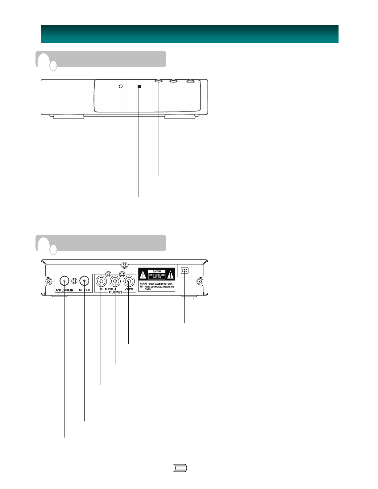
F
RONT PANEL
R
EAR PANEL
CH DOWN (▼)
Move down the TV channel.
REMOTE CONTROL SENSOR
Receives signals from Remote Controller.
POWER LED INDICATOR
Red light is displayed when the unit is turned off.
Green li
g
ht is displayed when the unit is turned on.
POWER
Turns the Converter Box on or off.
CH UP (▲)
Move up the TV channel.
AC Power Code
Connect the power cord.
VIDEO OUTPUT
Connect to your TV or VCR for Video output.
AUDIO OUPUT (L)
Connect to your TV or VCR for Audio(Left) output.
ANTENNA IN
Connect the AIR antenna cable here.
RF OUT
Use to connect your TV using RF cable.
※ CAX-03 and CAX-04 have analog pass-through.
~ Standby mode: Analog Pass-Through, Power on: RF Output (CH03/04)
AUDIO OUTPUT (R)
Connect to your TV or VCR for Audio(Right) output.
CAX-01/CAX-03/CAX-04 6
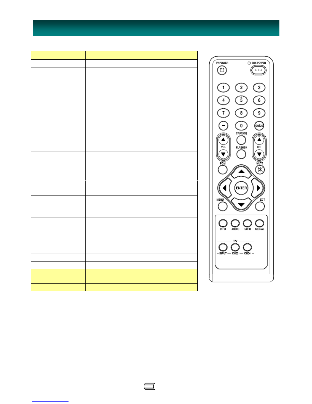
TV POWER Turns on/off power of TV
BOX POWER Turn on/off power of Converter Box.
Number(0~9)
Buttons
Select channel or enter password.
Dash(-)
Used to enter a program number for multiple
channels such as 1-1, 1-2, etc.
GUIDE View Electronic Program Guide.
VOL ▲ Increase the sound level.
VOL ▼ Decrease the sound level.
CAPTION Select closed caption: Off, CC, TEXT
FLASHBK Go to the previous channel.
CH ▲ Move the TV channel up.
CH ▼ Move the TV channel down.
PGM
Program the remote controller to match your TV
set.
MUTE Switch the sound On or Off.
◀ ▲▼ ▶ Move between categories in MENU.
ENTER
Adjust the settings to your preference.
Display current channel and time in TV viewing.
MENU
Display the MENU or the previous menu screen
that was displayed.
EXIT Completely exit from the menus.
INFO
Display information about TV program on the
screen.
AUDIO
Select available Multi tracks depending on the
broadcast. (Languages can be chosen only if
they are included in the TV program.)
RATIO Change the picture size.
SIGNAL Display the digital signal strength.
INPUT(TV) Select TV source (Tuner or AV input)
CH03(TV) Select channel 3 of TV
CH04(TV) Selects channel 4 of TV
I
NTRODUCTION – REMOTE CONTROLLE
R

7 CAX-01/CAX-03/CAX-04
Ensure that the following the Converter Box and accessories are included. If an accessory is missing, please
contact the dealer where you purchased the product.
Note
※ CAX-03 and CAX-04 have analog pass-through.
~ These models are
capable of passing through the analog signal to the TV set in standby mode.
1. Connect an antenna cable to the “ANTENNA IN" jack on the rear of the Converter Box.
2. Connect the “RF OUT” jack from the Converter Box to the “ANT IN” jack on your TV using the RF
cable supplied with the Converter Box.
User Manual
RF cable
Batteries
Remote Controller
Converter Box
I
NSTALLATION
• If you connect “RF OUT” of the Converter Box to ANT. IN of your TV, you can watch the video and the
audio of the Converter Box on Ch.3 or Ch.4 of your TV. The RF output channels can be selected in
output channel of menu-option. (Refer to page 15)
Quick Start Guide
P
ACKAGE CONTENTS
A
NTENNA CONNECTIONS
Converter Box’s Rear Panel
ANT IN
CAX-01/CAX-03/CAX-04 8
Note
• The VCR will record the onscreen display onto the tape during recording if:
- the channel is changed with CH (▲/▼)
- the sound level is adjusted with VOL (▲/▼)
or by pressing ENTER, etc.
• The caption signal is recorded because the display format is set only 480i.
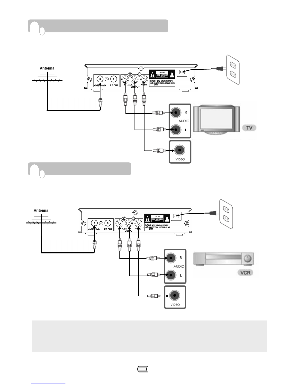
A
NALOG TV (MONITOR) CONNECTIONS
V
CR CONNECTIONS
1. Connect an antenna cable to the “ANTENNA IN" jack on the rear of the Converter Box.
2. Connect the “R-AUDIO-L” jacks and “VIDEO” jack from the Converter Box to the “A/V IN” jacks
on
your TV using RCA-type cables.
1. Connect an antenna cable to the “ANTENNA IN" jack on the rear of the Converter Box.
2. Connect the “R-AUDIO-L” jacks and “VIDEO” jack from the Converter Box to the “A/V IN” jacks on
your VCR using RCA-type cables.
Converter Box Rear Panel
TV Connection Panel
A/V IN
Converter Box Rear Panel
VCR Connection Panel
A/V IN
 Loading...