

Page 1

THERMOSEALER
OPERATING MANUAL
Page 2

Page 3

Cod. 97050483 - rev . 1 - 04/2012
ENGLISH
1
ENGLISH (TRANSLATION FROM THE ORIGINAL IN ITALIAN).
1. INTRODUCTION ................................................................................................. 3
1.1. APPLICABLE EUROPEAN DIRECTIVES .................................................. 3
1.2. INTENDED USE ........................................................................................... 3
1.3. PURPOSE OF THE MANUAL ...................................................................... 4
1.4. GENERAL WARNINGS ................................................................................ 4
2. CONTENTS OF THE PACKAGE ........................................................................ 5
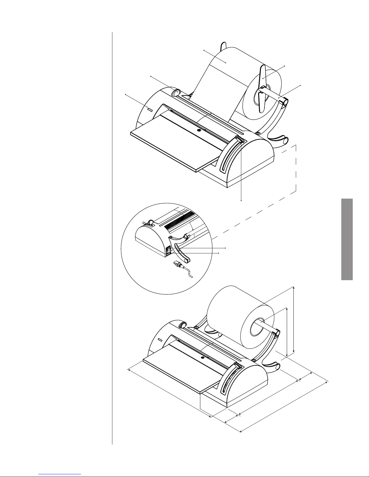
2.1. DIMENSIONS AND WEIGHT ....................................................................... 5
2.2. DESCRIPTION OF THE ITEMS................................................................... 5
3. PRODUCT PRESENTATION .............................................................................. 6
3.1. MAIN PERFORMANCES ............................................................................. 6
3.2 VIEWS (WITH DIMENSIONS) ..................................................................... 7
4. INSTALLATION ................................................................................................... 8
4.1. GENERAL PRECAUTIONS ........................................................................ 8
4.2. ELECTRICAL CONNECTION ...................................................................... 8
4.3. PRODUCT PREPARATION ......................................................................... 8
4.4. PAPER ROLL INSTALLATION ................................................................... 11
5. OPERATION ..................................................................................................... 12
5.1. PREPARATION .......................................................................................... 12
5.2. PAPER INSERTION ................................................................................... 12
5.3. WELDING AN END AND CUTTING .......................................................... 13
5.4. BAG RETURN AND FINISHING ................................................................ 14
6.
PREPARING THE MATERIAL TO BE SEALED .................................................15
6.1. MOVING THE MATERIAL .......................................................................... 15
6.2. CLEANING THE TOOLS ............................................................................ 15
6.3. WRAPPED MATERIAL .............................................................................. 15
APPENDIX A TECHNICAL CHARACTERISTICS ................................................... 16
SUMMARY TABLE ............................................................................................ 16
SAFETY DEVICES ............................................................................................ 16
APPENDIX C - MANTEINANCE .............................................................................. 17
GENERALS ....................................................................................................... 17
CLEANING ........................................................................................................ 17
BLADES REPLACEMENT ................................................................................ 17
FUSES REPLACEMENT .................................................................................. 17
APPENDIX D -
TROUBLESHOOTING ....................................................................18
APPENDIX G - DECLARATION OF CONFORMITY .............................................. 19
TABLE OF CONTENTS
REVISIONS
The following table lists subsequent editions/revisions of the manual.
The “Description” eld brief explains the subject of the latest revision.
Code Rev. Date Description
97050483 0 09-2011 First issue (translation from the original in Italian)
97050483 1 04-2012 Text and image adaptation
Page 4

ENGLISH
2
Page 5
ENGLISH
3
Dear Customer,
thank you for choosing this product. We hope it will perform to your full satisfaction.
This manual describes all procedures for the correct installation and use of the equipment.
Should you have any questions or suggestions concerning this product or our support, do not hesitate to
contact us.
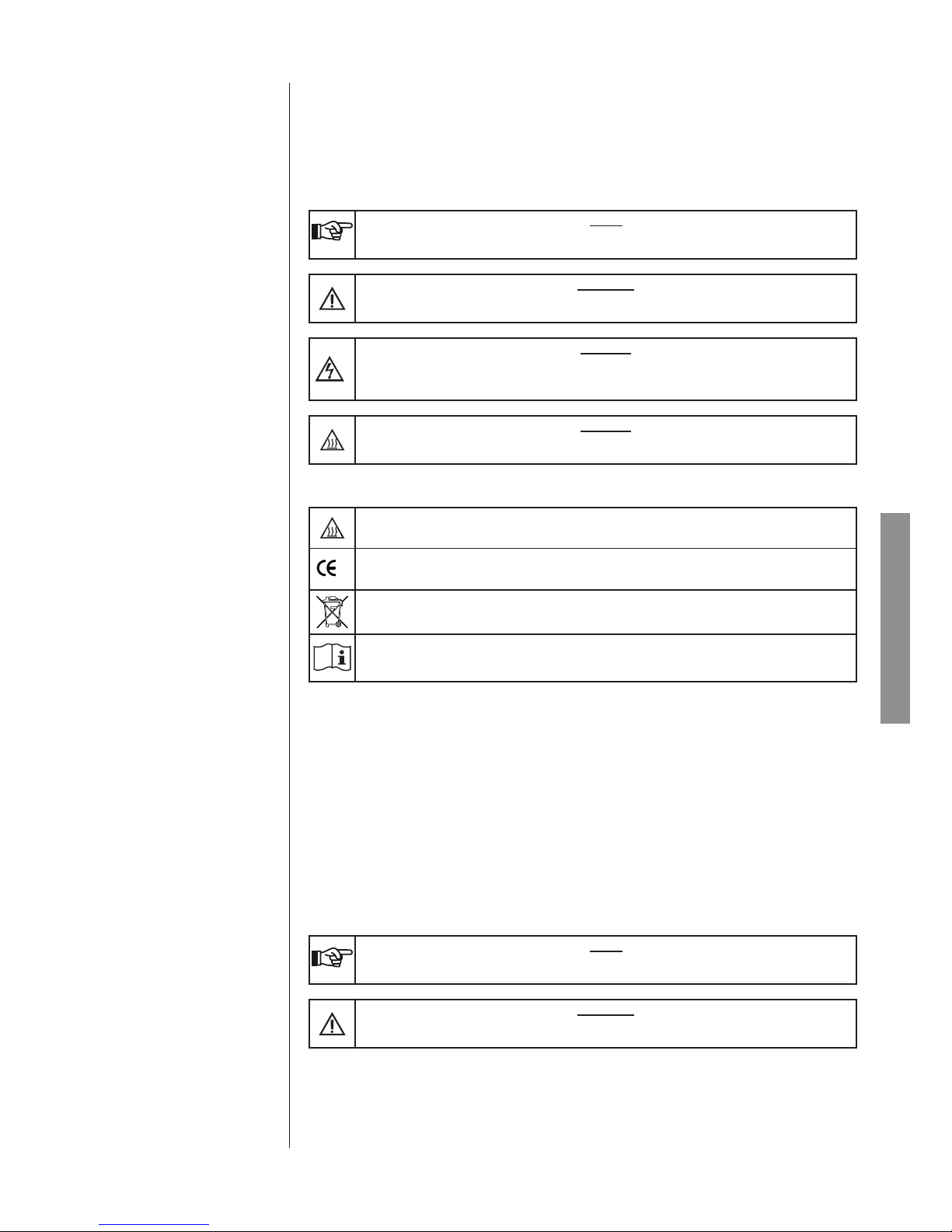
Note, warning and danger symbols used through the manual
NOTE
PAY SPECIAL ATTENTION; NOTES FOR PROPER INSTALLATION AND MAINTENANCE
PROCEDURES AND USE METHODS.
WARNING
THIS SYMBOL INDICATES A POTENTIAL DANGER OF INJURY. FOLLOW THE PROCEDURES DESCRIBED IN THE MANUAL TO AVOID INJURING THE USER AND/O
DANGER
THIS SYMBOL SIGNALS A POSSIBLE DANGER FOR PEOPLE. FOLLOW THE SUGGESTED PROCEDURE IN ORDER TO PREVENT POSSIBLE DAMAGE TO USERS AND/OR
OTHERS.
DANGER
POTENTIAL HAZARD DUE TO HIGH TEMPERATURE.
Symbols on equipment
Potential hazard due to high temperature.
Equipment in accordance with applicable directives.
Symbol for disposal in accordance with Directive 2002/95/EC, 2002/96/EC and 2003/108/EC.
Consult the user manual
The product described in this manual is manufactured in accordance with the highest safety standards and
doesn’t represent any danger for the operator if used according to the following instructions. The product is
in accordance with the following European Directive as applicable:
2006/95/EC, for the approximation to the legislation of the Members States related to low voltage equip-
ment.
2004/108/EC, for the approximation to the legislation of the Members States related to the electromagnetic
compatibility;
The unit is meant for professional use and can only be employed for the purpose it was designed for, that
is the thermo-sealing and cutting of sterilization paper/polypropylene rolls.
NOTE
THE UNIT CANNOT WORK WITH ROLLS OF A MATERIAL OTHER THAN THE ONES STATED ABOVE.
WARNING
THE DEVICE MUST ONLY BE USED BY QUALIFIED PERSONNEL. IT MAY NOT BE USED
OR HANDLED BY INEXPERT AND/OR UNAUTHORIZED PERSONNEL FOR ANY REASON.
1. INTRODUCTION
1.1. APPLICABLE
EUROPEAN DIRECTIVES
1.2. INTENDED USE
Page 6
ENGLISH
4
NOTES
THE INFORMATION IN THIS MANUAL IS SUBJECT TO CHANGE WITHOUT NOTICE.
THE MANUFACTURER IS NOT RESPONSIBLE FOR DIRECT, INDIRECT, ACCIDENTAL OR
CONSEQUENTIAL DAMAGES OR ANY OTHER DAMAGES RELATING TO THE PROVISION/
USE OF THIS INFORMATION.
NO PART OF THIS DOCUMENT MAY BE REPRODUCED, ADAPTED OR TRANSLATED IN
ANY FORM OR BY ANY MEANS WITHOUT THE PRIOR WRITTEN PERMISSION OF THE
MANUFACTURER.
FOR CORRECT INTERPRETATION OF THE INSTRUCTIONS CONTAINED IN THIS MANUAL, THE ITALIAN VERSION SHALL BE VALID AS ORIGINAL TEXT.
The manual purpose is to provide instructions for:
- General knowledge of the product;
- Correct installation;
- Its safe and efcient use;
- The treatment of tools and/or materials to submit to sterilization.
More the appendix includes:
- The technical features of the product;
- Maintenance operations;
- Troubleshooting and solutions;
- Other documentation.
The product must always be used according to the procedures included in this manual and never for purposes other than the ones indicated.
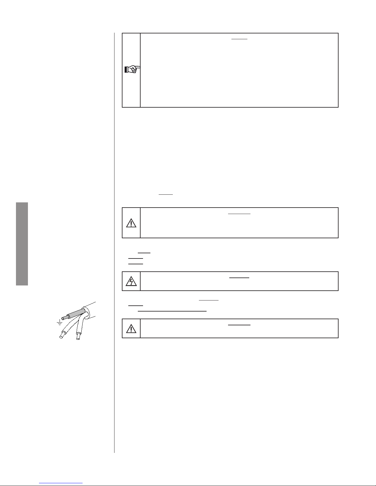
WARNING
THE USER IS RESPONSIBLE FOR ALL LEGAL REQUIREMENTS RELATED TO THE
INSTALLATION AND USE OF THIS PRODUCT. THE MANUFACTURER WILL NOT BE
RESPONSIBLE FOR ANY BREAKAGE, MALFUNCTIONS, PROPERTY DAMAGE OR INJURY
IN THE EVENT THAT THE PRODUCT IS NOT INSTALLED OR USED CORRECTLY.
Please observe the following precautions in order to avoid injury or property damage; in particular:
- Use ONLY recommended cleaning detergents.
- Do not pour water or other liquids or inammable products on the equipment.
- Do not use the equipment in the presence of gas or explosive or inammable vapors.
DANGER
BEFORE CARRYING OUT ANY MAINTENANCE OPERATION, ALWAYS DISCONNECT THE
POWER CABLE PLUG FROM THE POWER SOCKET.
- Make sure the electrical system is grounded conforming to current laws and/or standards;
- Do not remove any label or nameplate from the device; request new ones, if necessary.
- Use only original replacement parts.
WARNING
THE FAILURE TO OBSERVE THE ABOVE, RELEASES THE MANUFACTURER FROM ALL
LIABILITY.
1.3. PURPOSE OF THE MANUAL
1.4. GENERAL WARNINGS
Page 7
600
260
300
9
8
10
6
5
2
1
4
7
3
11
ENGLISH
5
NOTE
CHECK THE INTEGRITY OF THE PACKAGE UPON RECEIPT.
Once the package is opened, check that:
- the supply matches the specications of the order (see the accompanying document);
- that there is no obvious product damage.
Size and weight MILLSEAL PLUS
Height 260 mm
Width 600 mm
Depth 300 mm
Overall weight 6 kg
NOTE
IN THE CASE OF A WRONG PRODUCT, MISSING PARTS OR ANY TYPE OF DAMAGE,
IMMEDIATELY PROVIDE A DETAILED DESCRIPTION TO THE RESELLER AND THE
TRANSPORTER THAT MADE THE DELIVERY.
NOTE
KEEP THE ORIGINAL PACKAGING AND USE IT WHENEVER THE DEVICE IS TO BE
TRANSPORTED. THE USE OF DIFFERENT PACKAGING COULD DAMAGE THE PRODUCT
DURING SHIPMENT.
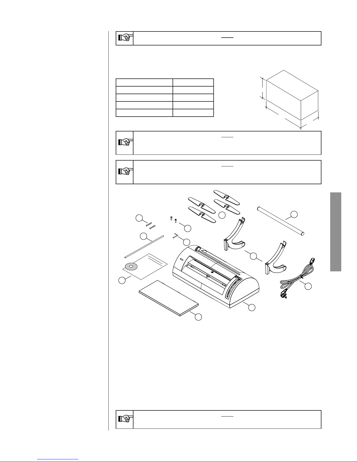
1 Paper-stop barrier
2 2 screws
3 4 aiming devices
4 Allen wrench
5 Roll holder tube
6 2 roll supports
7 Operator documentation
8 Millseal Plus Thermo-sealing machine
9 Table area
10 Power lead
11 2 fuses
NOTE
THE CUSTOMER MUST KEEP THE WARRANTY CERTIFICATE TOGETHER WITH THE
RECEIPT.
2. CONTENTS OF THE
PACKAGE
2.1. DIMENSIONS AND WEIGHT
2.2. DESCRIPTION OF THE
ITEMS
Page 8
ENGLISH
6
Millseal Plus is the thermo-sealing machine which ts as a natural complement to the range of steam sterilisers.
It is an elegantly, space-saving designed piece of equipment that is both user-friendly and reliability, even
with heavy use.
Millseal Plus is therefore a useful option for all those users who require professional equipment with an
excellent ratio of quality to price and performance.
Millseal Plus is an electronically controlled thermo-sealer with a sealing band of 12 mm t to resist the
sterilization processes of the modern sterilizers featuring fractioned pre-vacuum, and to assure in time the
sterility of the packages.
Efcient heat control in the welding area is achieved thanks to the automatic temperature adjustment, ensuring high and constant performance.
The solid structure in plastic and aluminium and the ergonomic and minimalist shape help to maintain a high
level of hygiene, weight and overall size and excellent stability during use.
All this with the objective of offering a product suited to the daily needs in the medical area.
NOTE
FOR THE DESCRIPTION OF THE SECURITY DEVICES, REFER TO APPENDIX A
(TECHNICAL CHARACTERISTICS)
For a good operation of the thermo-sealer the rst and essential task is its correct installation; in this way
possible malfunctions or damages to the unit will be avoided.
3. PRODUCT
PRESENTATION
3.1. MAIN PERFORMANCES
Page 9
474
85
MAX
85
374
MAX
544
MAX 260
200
ENGLISH
7
Paper roll for autoclave
Roll holder
Aiming device
Cutting handle
Welding lever
Warning LED
Switch
Power lead outlet with fuse
holders
3.2 VIEWS (WITH DIMENSIONS)
Page 10
A
A
B
B
C
A
ENGLISH
8
Therefore please read carefully the notes and warnings reported in the rest of this chapter.
NOTE
THE TECHNICAL SERVICE IS AT YOUR DISPOSAL, TO CLEAR ANY QUESTIONS OR
PROVIDE FURTHER INFORMATION.
ATTENTION
THE ELECTRICAL INSTALLATION MUST BE PROVIDED WITH EARTH CONNECTION.
- Install the thermo-sealer on a at surface, leaving enough room for its operation and adequate ventilation.
- Makes sure that the resting plane is strong enough to support the unit and roll weight (max 15 kg);
- Do not install near sinks to avoid contact with water or liquids that could cause short circuits or situations
potentially dangerous for the operator;
- Do not install in humid or poorly ventilated environments;
- Do not install in environment with the presence of inammable and/or explosive gas or steams;
- Install the unit so that the power supply cable is not bent or pressed along its route up to the mains socket.
In compliance with the standing regulations, the unit must be connected to a mains socket of the electrical
installation with power rating suitable for the unit consumption and provided with earth connection.
The socket must be suitably protected upstream by a terminal board provided with electro thermal magnetic
switch and differential switch.
Connect the supplied power cable to the mains socket on the rear of the equipment.
NOTE
ONLY USE THE POWER SUPPLY CABLE PROVIDED WITH THE UNIT; POSSIBLE PLUG
REPLACEMENT IS UNDER THE FULL RESPONSIBILITY OF THE USER.
DIRECTLY CONNECT THE POWER SUPPLY CABLE TO THE SOCKET. DO NOT USE
EXTENSIONS, ADAPTERS OR OTHER ACCESSORIES.
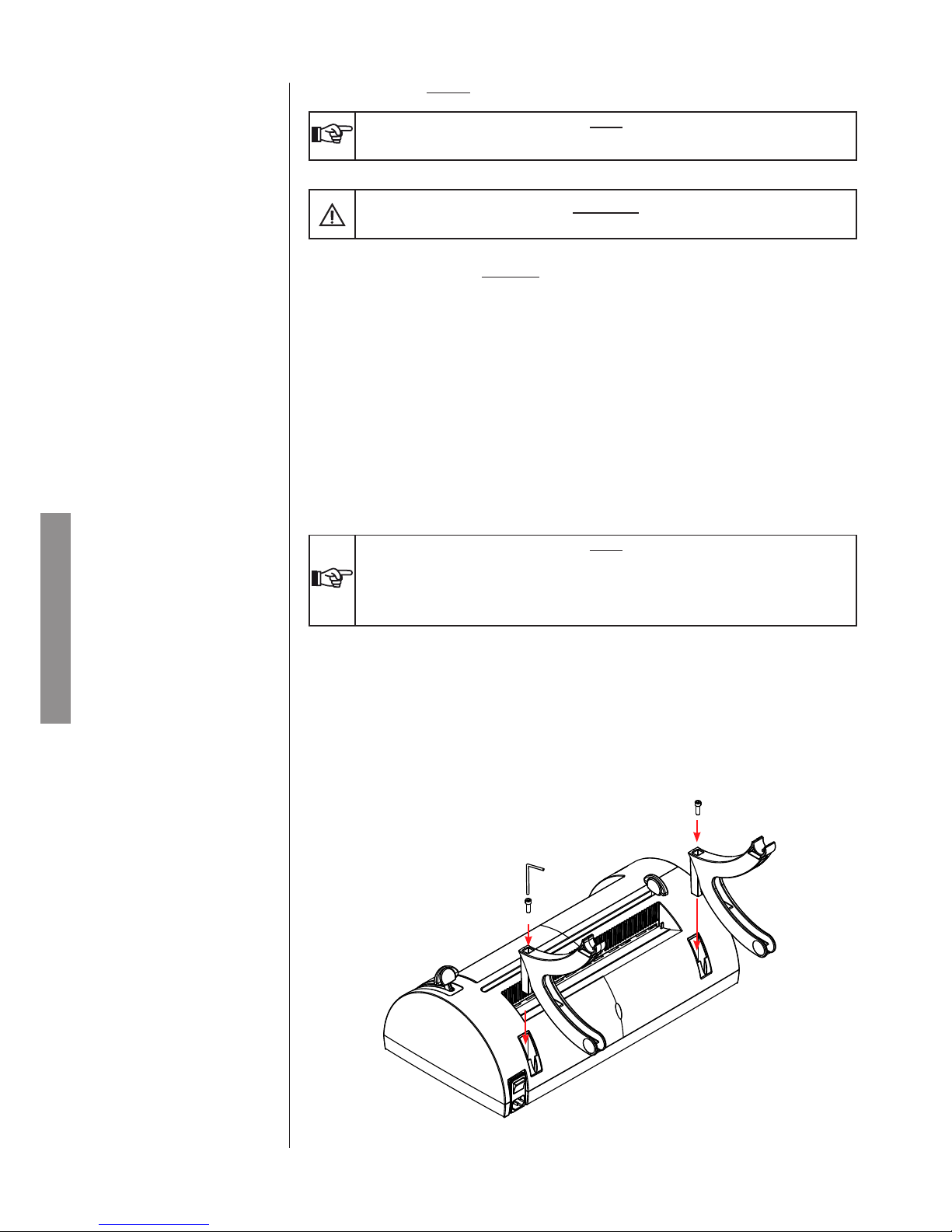
1. Carefully remove the package contents.
2. Insert the roller supports (A) in the appropriate holders.
Tighten the two screws (B) with the provided Allen wrench (C)
4. INSTALLATION
4.1. GENERAL PRECAUTIONS
4.2. ELECTRICAL CONNECTION
4.3. PRODUCT PREPARATION
Page 11
A
A
D
E
F
G
I
I
I
H
ENGLISH
9
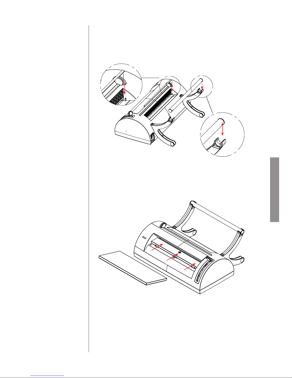
3. Insert the roll holder tube (D) in the supports (A), checking that the holes at the end of the tube properly
engage in the teeth (E) present on the supports (A).
Rest the paper stop barrier (F) in the compatible holders (G).
4. Insert the table area (H) in the appropriate slots (I).
Page 12
J
ENGLISH
10
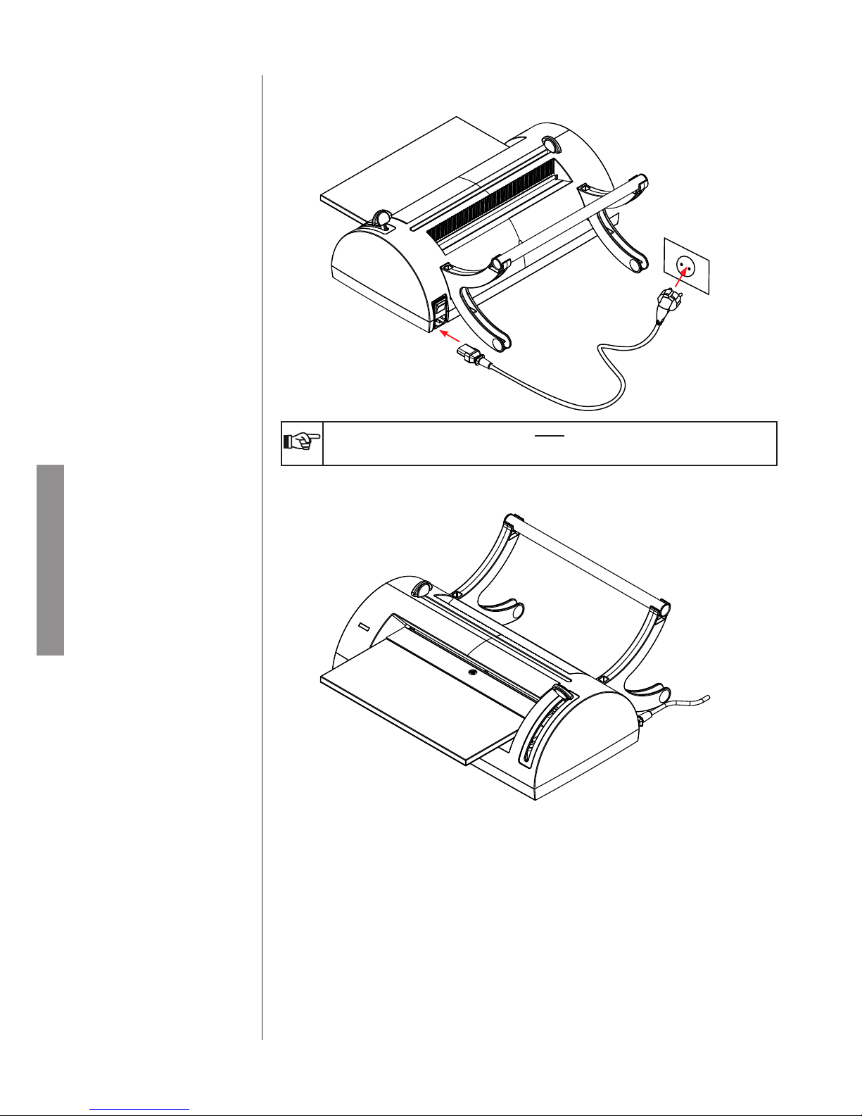
5. Connect the power lead (J).
6. The thermo-sealing machine is now ready for use.
NOTE
POSITION THE MACHINE IN SUCH A WAY THAT THE ENDS OF THE CABLE ARE EASILY
ACCESSIBLE.
Page 13
ENGLISH
11
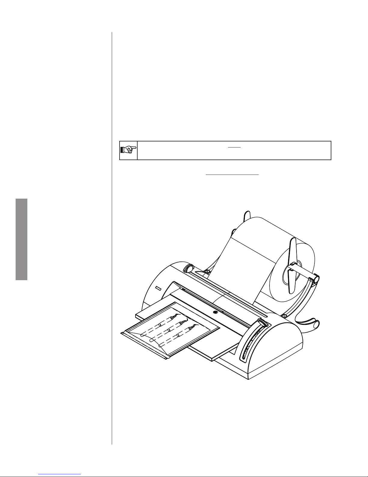
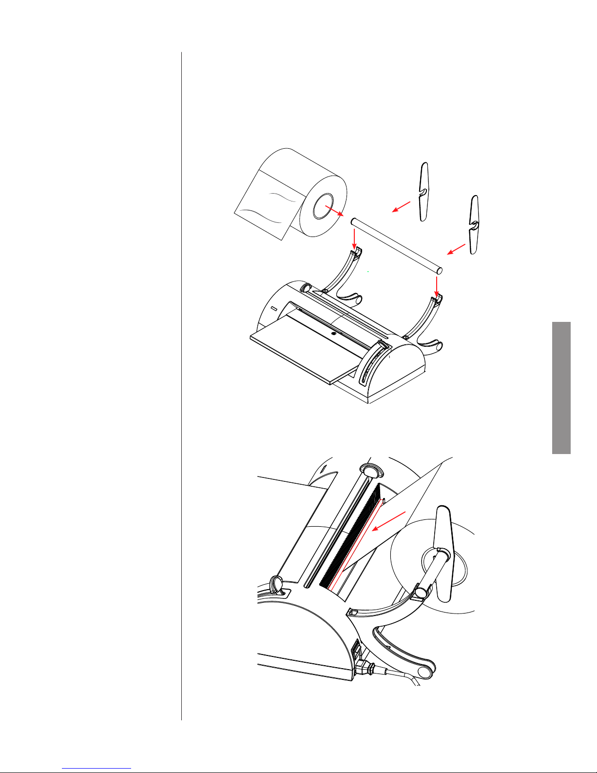
- Insert the paper roll on the roll holder tube.
- Install the roll holder/roll unit on the arm holders (as described in the previous paragraph), positioned in
such a way that the paper belt unrolls downward and with the polypropylene lm in view, taking care to
have the sheet pass under the paper-stop barrier.
- Finally, fasten the aiming devices.
4.4. PAPER ROLL INSTALLATION
Page 14
C
A
X+ 8 cm
X
B
ENGLISH
12
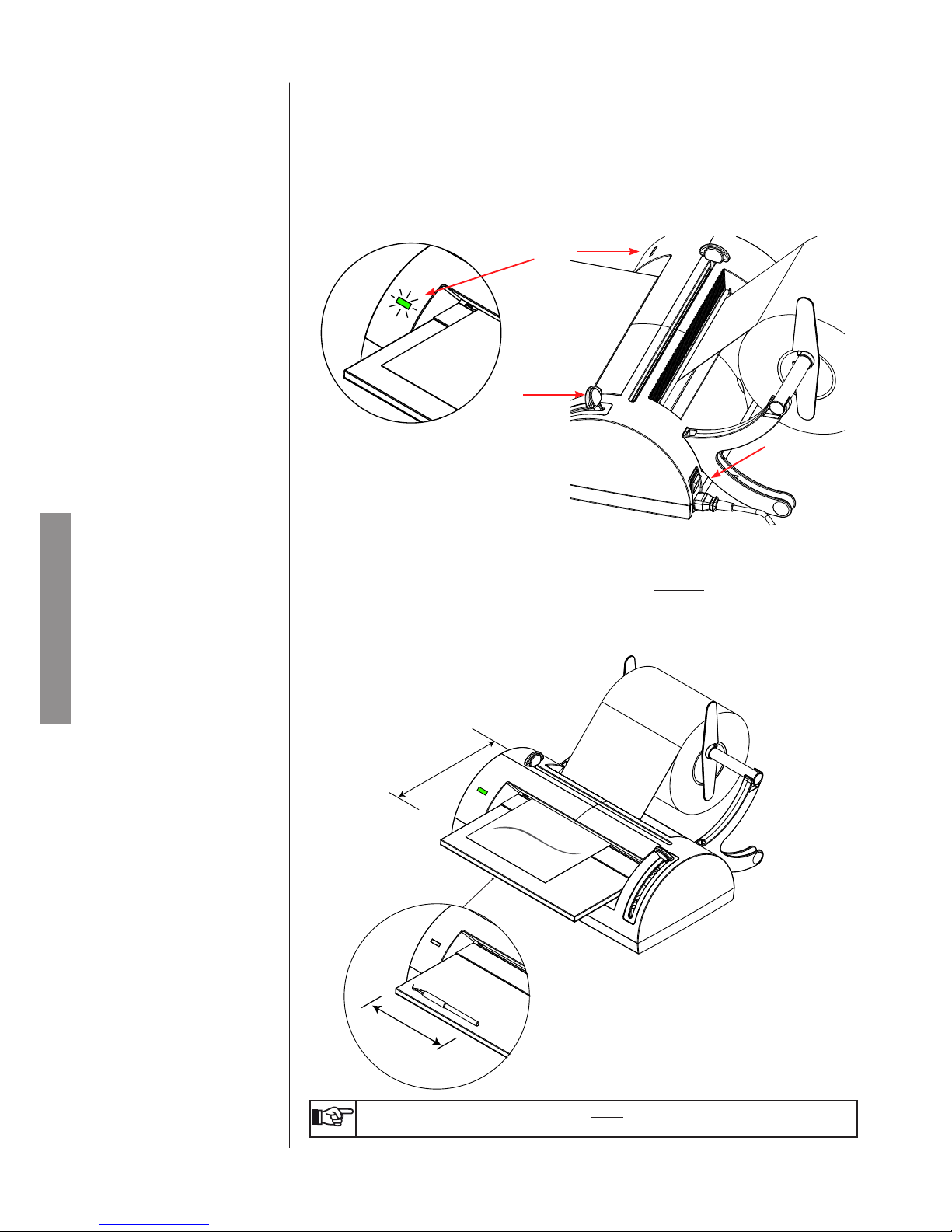
- Verify that the welding lever (B) is positioned at the highest end of the guide.
Switch on the machine via the switch (A) located on the rear part.
- The frontal green LED (C) will ash.
- Heating resistance is powered and the temperature will increase gradually.
When the ideal level for proper welding is reached, the frontal green LED will remain xed on, emitting
an acoustic signal.
- Have the paper belt pass under the paper-stop barrier and insert it in the rear slot. Then remove it from
the front to the desired length. (see paragraph 5.3)
- It is best to pull the paper out to a length equal to that of the tool plus 8 cm to allow proper welding of the
edge.
5. OPERATION
NOTE
BAGS SHORTER THAN 7 CM ARE NOT RECOMMENDED.
5.2. PAPER INSERTION
5.1. PREPARATION
Page 15
BEEP
1
C
2
BEEP
B
1
C
D
2
B
ENGLISH
13
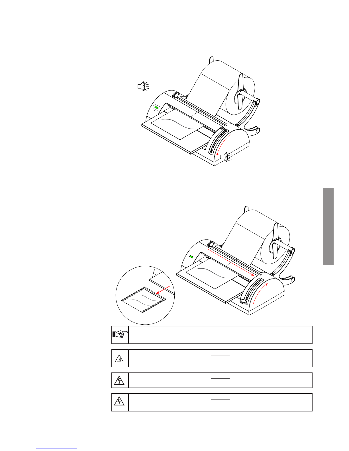
- Lower the lever (B) from position 1 to position 2. The green LED (C) will ash quickly until welding has
nished, indicated by an acoustic signal.
- Slide the cutting lever (D) to the opposite end.
- Lift the lever (B) from position 2 to the original position 1.
- The frontal LED will return to a xed green once again, and the acoustic signal will switch off. The bag
is now sealed on one end.
NOTE
IF THE LEVER DOES NOT LIFT AFTER A FIRST ACOUSTIC SIGNAL, THE SEALING MACHINE WILL EMIT ANOTHER TONE AND THE LED WILL FLASH RED.
DANGER
DO NOT PUT FINGERS IN THE WELDING AREA WHEN THE MACHINE IS ON AND IMMEDIATELY AFTER IT HAS BEEN SWITCHED OFF.
DANGER
DO NOT PUT FINGERS IN THE CUTTING LEVER SLOT.
DANGER
DO NOT LEAVE PAPER INSERTED IN THE SEALING AREA WHEN THE MACHINE IS NOT
IN USE.
5.3. WELDING AN END AND
CUTTING
Page 16
F
G
ENGLISH
14
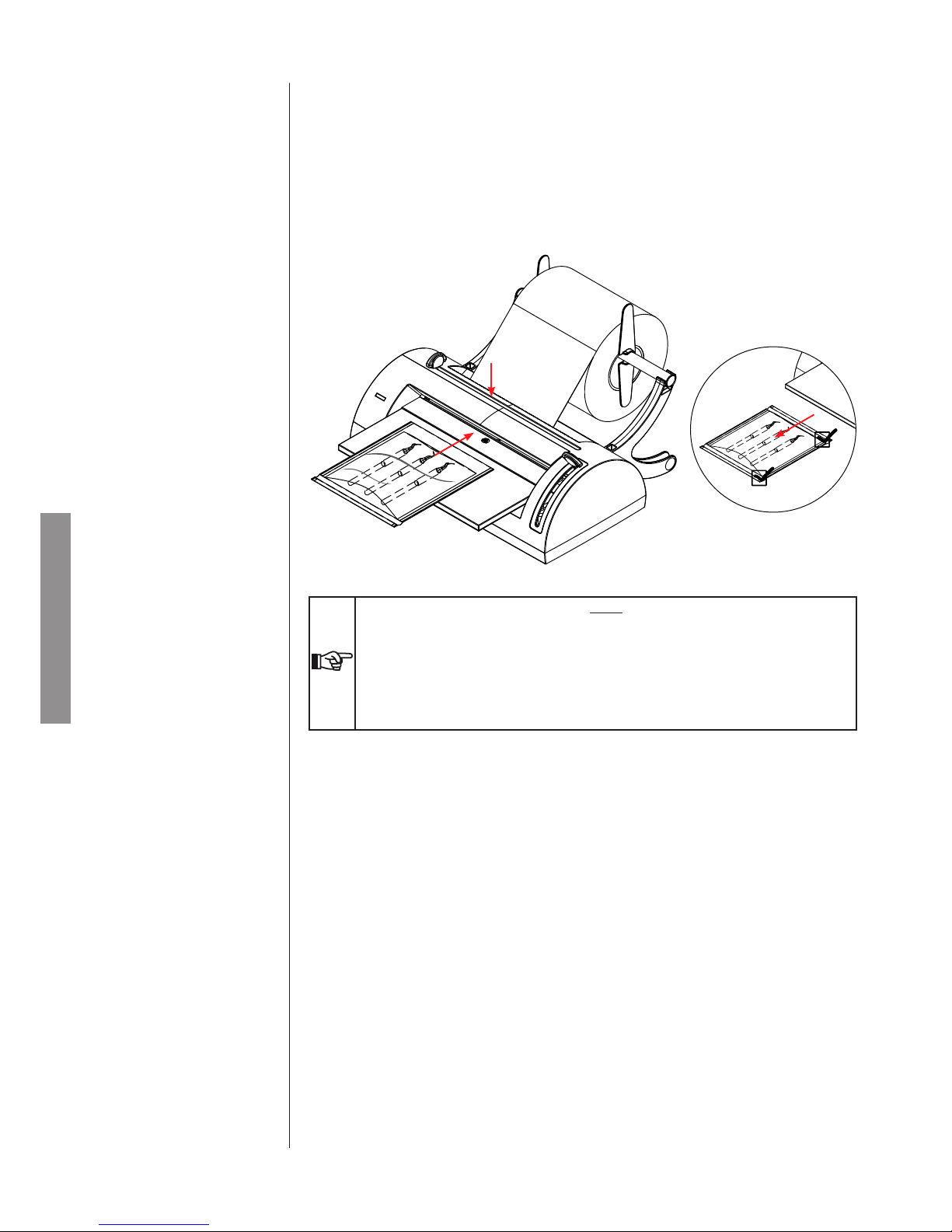
- Insert the instruments in the open side of the bag, following the warnings contained in the chapter “Material preparation” (see following page).
- Insert the unwelded end of the bag in the front slot (F) a few centimetres, until the end of the bag is aligned with the upper slot (G).
- Perform sealing operations as previously described.
NOTE
AFTER A PERIOD OF INACTIVITY OF 30 MINUTES, THE MACHINE WILL GO INTO STANDBY MODE, SWITCHING OFF THE HEATING RESISTANCE.
STAND-BY STATUS IS SIGNALLED BY PERIODIC DOUBLE-FLASHING OF THE GREEN
LED.
TO RESET MACHINE OPERATION, LOWER AND LIFT BACK UP THE WELDING LEVER.
THE MACHINE WILL REACTIVATE THE HEATING RESISTANCE (FLASHING GREEN LED)
WAIT FOR THE MACHINE TO HAVE REACHED THE IDEAL TEMPERATURE ONCE AGAIN
(FIXED GREEN LED) BEFORE STARTING USE AGAIN.
5.4. BAG RETURN AND
FINISHING
Page 17

ENGLISH
15
The sterilization process can be considered as effective, reliable and repeatable on condition that the instru-
ments and the materials in general are rst properly treated and subsequently correctly positioned inside
the sterilization chamber.
This foresight is even more required when we consider objects within an envelope.
It must be stressed that organic residue or deposit of substances used in the medical practice inevitably
become receptacle of micro-organisms and can hamper the steam sterilization process.
An improper arrangement of the load makes difcult and sometimes impossible the circulation of water
steam on the material and/or inside its cavities, with the consequences that can be imagined.
Therefore we provide a few basic indications concerning these aspects, leaving the customers with the task
of improving their knowledge on the matter in the best fashion.
When handling and moving contaminated material, it is good practice to take the following precautions:
- Always wear rubber gloves with adequate thickness;
- Clean with a germicide detergent the hands protected with the gloves;
- Always use a tray for carrying the tools.
- Never carry the tools directly in your hands;
- Pay attention to any sharp or cutting parts to avoid the risk of infections;
- Separate the objects that must not undergo a sterilization or cannot stand the process;
- When you have nished handling the material, carefully wash your hands still gloved.
All materials and/or tools to be sterilized must be perfectly cleaned and without trace of any kind of residue
(organic and inorganic materials, paper fragments, cotton or gauze swabs, scale, etc.).
Otherwise, the sterilization process could turn out to be not effective, and the sterilizer and the tools themselves undergo irreversible damage.
For an effective cleaning:
- After use, immediately rinse the tools with a jet of running water;
- Divide the tools according to the type of material (carbon steel, stainless steel, brass, aluminium, chrome
etc.) to avoid processes of electrolytic oxidation-reduction;
- Carry out a washing with an ultrasonic cleaner containing a mix of water and germicide solution, carefully
following the manufacturer’s recommendations.
- Carefully rinse and check that the cleaning is complete; if necessary repeat the washing cycle or clean
manually.
- Dry perfectly.
Before the sterilization, check the indications provided by the manufacturer of the tool/ material, checking
any incompatibility.
Meticulously follow the use procedures for detergent or disinfectant products and the instructions for the
washing and automatic lubrication equipment.
The use of sterilization paper envelopes allows both an optimal sterilization and to maintain in time the
sterility condition.
Follow these general indications:
- Envelope the tools one by one or make sure that they are made of the same material;
- Close the envelope with the thermo-sealer.
- Do not use metal points, pins or similar since they do not warrant sterility;
- Arrange the envelopes so as to avoid the creation of air pockets that prevent the correct penetration and
the removal of the steam.
- If possible, arrange the envelopes vertically using a suitable support.
- Never overlap the envelopes one over the other.
6.
PREPARING THE
MATERIAL TO BE
SEALED
6.1. MOVING THE MATERIAL
6.2. CLEANING THE TOOLS
6.3. WRAPPED MATERIAL
Page 18

ENGLISH
16
Device Thermo-sealer
Model MILLSEAL PLUS
Manufacturer
Castellini S.p.A.
Via Saliceto, 22
40013 Castel Maggiore (BO) - ITALIA
Power supply voltage 220-240 V~
Frequency 50-60 Hz
Mains fuses (5 x 20 mm) T 3,15 A - 250V
Nominal power 150 W
Insulation class (IEC 61010-1) Class I
Installation category (IEC 61010-1) Cat. II
Utilization Internal use
Operating environment conditions
Temperature: +15°C ÷ +35°C
Relative humidity: 80% (max), without condensation
External dimensions (without roll) (L x D x H) 474 x 374 x 200 mm
Net weight 5 kg
Type of sealing With continuous cycle and constant temperature
Nominal operating temperature of the heating resistance
180°C
Max sealing length 12 mm
Maximum welding width 300 mm
Sealable material Paper /polypropylene lm
Max diameter of the roll 200 mm
Maximum roll widthl 300 mm
Orientation of the paper /polypropylene lm Polypropylene lm oriented upward
The data plate is placed back on the unit.
The thermo-sealer is equipped with the following safety devices, of which we list a short description along
with their function:
- Mains fuses (see data in the above table)
Equipment protection from internal electrical faults.
Action: break the electrical power supply.
- Automatic off of the heating circuit
If the lever is not lifted back up after sealing has been completed, the heating circuit will be automatically
deactivated. This operation will be indicated by an acoustic signal and intermittent red LEDs.
- Anti- nger crushing design
Protection from accidental crushing of ngers during lever movement.
- Automatic Stand-By System.
After a period of inactivity of 30 minutes, the machine will go into stand-by mode, switching off the hea-
ting resistance.
This device protects from risks of overheating caused by a failure to switch off the machine at the end of
use, creating signicant energy conservation at the same time.
- Protected cutting knife
Exclusive design with cutting knife totally inaccessible from outside.
SAFETY DEVICES
APPENDIX A TECHNICAL CHARACTERISTICS
SUMMARY TABLE
Page 19
ENGLISH
17
The equipment does not need any special care; it is only recommended that the user cleans it periodically.
In all cases carefully follow the procedure detailed below.
In case of replacement of equipment components, request and use ONLY ORIGINAL SPARE PARTS.
DANGER
BEFORE PERFORMING ANY MAINTENANCE OPERATION, DISCONNECT THE PLUG OF
THE POWER SUPPLY CABLE FROM THE SOCKET.
ATTENTION
MAKE SURE THAT THE MACHINE HAS COOLED BEFORE ANY MAINTENANCE
OPERATION.
Clean the equipment externally with a clean cloth dampened with water and neuter detergent.
NOTE
- DO NOT USE PRODUCTS CONTAINING ISOPROPYL ALCOHOL (2-PROPANOL,ISO-
PROPANOL).
- DO NOT USE PRODUCTS THAT CONTAIN SODIUM HYPOCHLORITE (BLEACH).
- DO NOT USE CLEANERS THAT CONTAIN PHENOL
Perfectly dry the surfaces and remove any remaining resistant residue.
Always keep in mind the following general warnings:
- Do not submit the unit to direct water jets, under pressure or sprinkling. Any inltration on the internal
electrical components could irremediably damage its operation;
- Do not use abrasive sponges, metal brushes (or other aggressive materials) or products for cleaning of
metal, both solid and liquid.
The blade must be replaced periodically or when paper cutting problems are noticed.
Contact technical support.
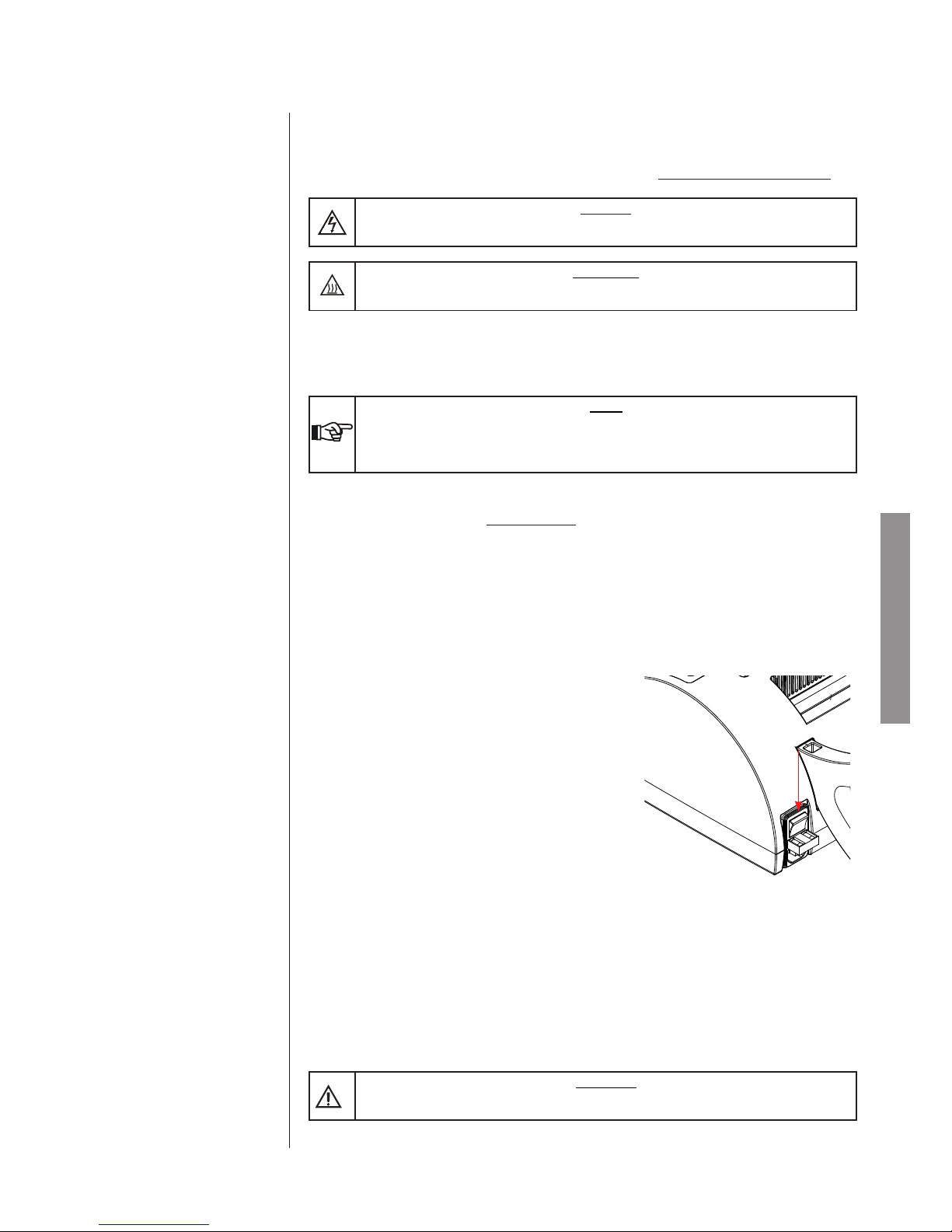
The fuses are in the fuse holder above the power lead outlet.
- Remove the power lead plug.
- Remove the fuse holder box with a screwdriver.
- Replace the fuse with one of equal value (see appendix A).
In accordance with Directives 2002/95/ EC, 2002/96/ EC and 2003/108/ EC, regarding the reduction in use
of dangerous substances in electrical and electronic equipment, as well as waste disposal, such equipment
may not be disposed of as normal urban waste and must be separated accordingly. When purchasing a
new, equivalent piece of equipment, the old piece of equipment that has reached its end-of-life must be
handed over to the reseller for proper disposal. The Manufacturer will carry out the functions dened by
individual national legislation with respect to the reuse, recycling and other forms of salvaging of the abovementioned waste.
The proper collection and separation of such equipment for recycling, treatment and disposal helps avoid
any possible negative effects on the environment and health and facilitates the recycling of the materials of
which the equipment is made. The crossed out rubbish can symbol indicates that the product, at the end-oflife, must be collected separately from other types of waste.
WARNING!
IMPROPER DISPOSAL OF THE PRODUCT RESULTS IN THE APPLICATION OF SANCTIONS
WHICH ARE DEFINED BY INDIVIDUAL NATIONAL LAWS.
APPENDIX C - MANTEINANCE
DISPOSAL AT END-OF-LIFE
GENERALS
BLADES REPLACEMENT
FUSES REPLACEMENT
CLEANING
Page 20
ENGLISH
18
APPENDIX D -
TROUBLESHOOTING
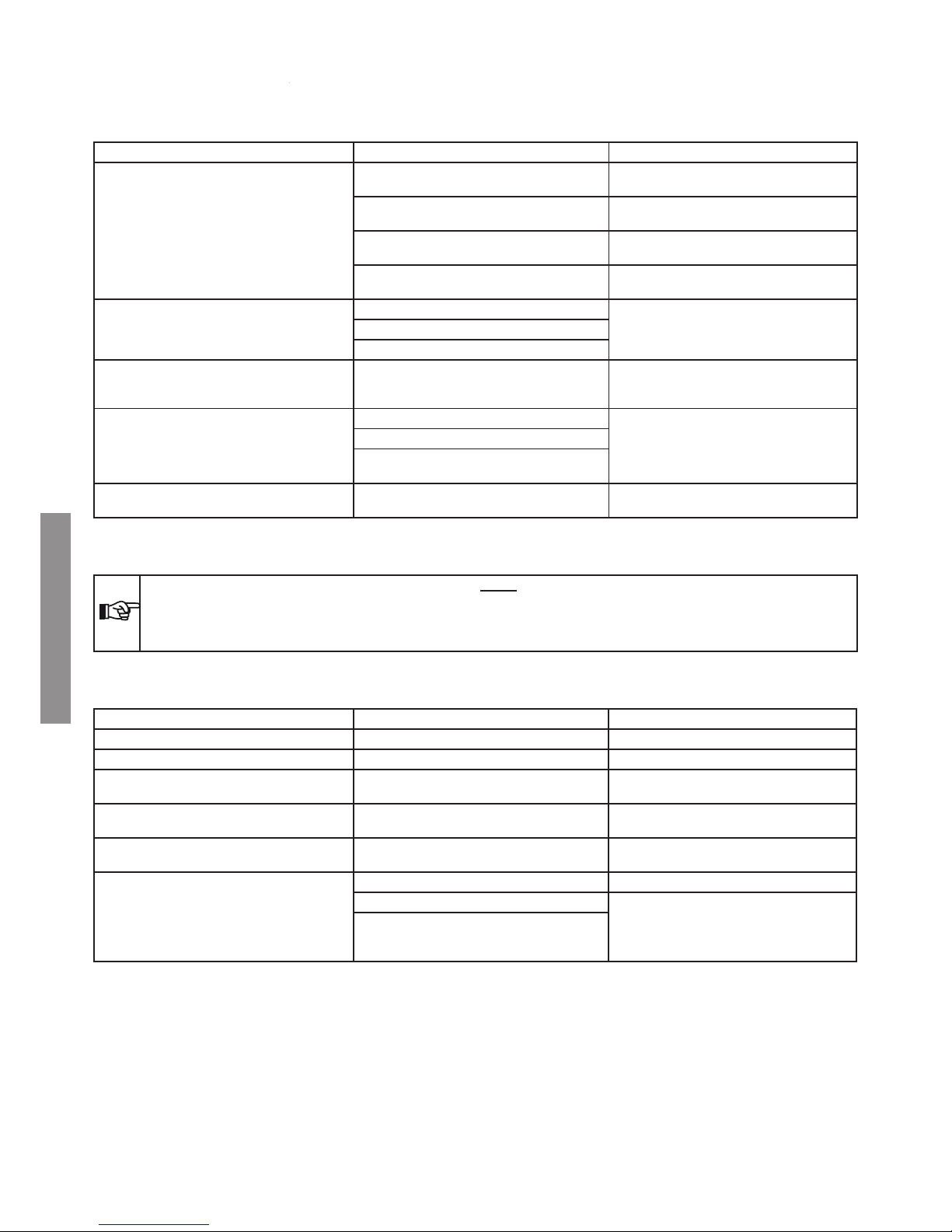
If Your Thermo-sealer does not work correctly, carry out the following checks before contacting the Technical Service:
PROBLEM POSSIBLE CAUSE SUGGESTED SOLUTION
The thermo-sealer does not switch on.
The plug of the power supply cable is not inserted in the outlet.
Properly put in the plug.
Lack of power at the power supply outlet.
Check the possible cause of power failure and
try to solve it.
The magneto thermal switch and/or differential
switch of the installation are OFF.
Put the switches to ON position.
Mains fuses broken
Replace the fuses
(see Appendix C - Maintenance)
The LED does not ash when the thermo-sealing
machine is switched on
The Led does not work.
Contact the Technical Support Service Heating resistance broken.
Fault in the electronic card.
Bag sealing is performed but the LED remains
a xed green (instead of red) and no acoustic
signals are heard.
Fault of the end-of-run microswitch. Contact the Technical Support Service
Insufcient pressure in the sealing area.
Contact the Technical Support Service
Silicon rubber prole damaged.
Resistance does not reach the operating temperature
Envelope cutting is difcult. Consumed blades. Contact the Technical Support Service
NOTE:
SHOULD THE PROBLEM PERSIST, PLEASE CONTACT OUR TECHNICAL SERVICE NETWORK REPORTING THE THERMOSEALER MODEL AND ITS SERIAL NUMBER.
THESE DATA CAN BE FOUND ON THE FACTORY PLATE PLACES ON THE UNIT REAR.
Operator warning signal
SIGNAL CAUSE ACTION
The LED is ashing green The machine is warming up Wait until the machine warms up.
The LED is steady green The machine is ready for use -
The LED is fast ashing green
The sealing lever has been lowered and the
machine is in use
Wait for the acoustic signal, lift the lever and
remove the bag
The green LED emits a brief ash every 5 seconds
The machine is in a paused status after a period of inactivity of 30 minutes.
Lower and lift back up the lever to rest normal
operation.
The red and green LEDs ash at the same time The machine signals the presence of a heating
system problem.
Switch off and retry machine use.
If the signal recurs, contact Technical Support.
The LED is solid red and the machine is emitting
an acoustic signal
The sealing operation has been completed Lift the lever and remove the bag
The machine is on with the sealing lever down
Lift the lever
The sealing lever was lowered before reaching
the proper operating temperature
Page 21

97010027 rev.1 Aprile 2012
DICHIARAZIONE DI CONFORMITÀ
DECLARATION OF CONFORMITY
DECLARATION DE CONFORMITE
KONFORMITÄTSBESCHEINIGUNG
DECLARACION DE CONFORMIDAD
Applicazione delle Direttive CE 2006/95 – 2004/108.
Application of the EC Directives 2006/95 - 2004/108.
Application des Directives CE 2006/95 - 2004/108.
Anwendung der EG Vorschriften 2006/95 - 2004/108.
Aplicación de las Directivas CE 2006/95 - 2004/108.
Descrizione del materiale: Termosigillatrice Modello: TERMOSIG. MILLSEAL PLUS MAN.
Description of goods: (Thermal sealer) Model:
Description des marchandises: Modèle:
Warenbezeichnung: Modell:
Descripción del material: Modelo:
Numero di serie: 11MY0374
Serial number:
Numéro de série:
Seriennumer:
Número de serie:
Nome del Fabbricante: CASTELLINI S.p.A.
Name of Manufacturer:
Nom du Fabricant:
Name des Herstellers:
Nombre del Fabricante:
Indirizzo del Fabbricante: Via Saliceto, 22 – Castel Maggiore (BO) – Italy
Address of Manufacturer:
Adresse du Fabricant:
Adresse des Herstellers:
Dirección del Fabricante:
Costruito in: ITALIA
Made in: (ITALY)
Fabriqué à:
Hergestellt in:
Fabricado en:
Il sottoscritto dichiara che il materiale di cui sopra è interamente conforme alle Direttive CE 2006/95, 2004/108.
The undersigned hereby declares that the above mentioned goods entirely conform to the EC Directives 2006/95, 2004/108.
Le soussigné déclare que le materiel cité plus haut est èntierement conforme à les Directives CE 2006/95, 2004/108.
Der Unterzeichnete erklärt, daß die obengenannte Ware vollständig der EG Vorschriften 2006/95, 2004/108 entsprechen.
El abajo firmante declara que el material arriba descrito es enteramente conforme a las Directivas CE 2006/95, 2004/108.
Standard di riferimento: EN 61010-1:2001
Reference standards: EN 61326-1:2006
Conforme aux normes:
Angewendete Standards:
Referencias Standard:
15/05/2012
____________________________ ___________________________________
Castel Maggiore, Data - Date - Le - Datum - Fecha Firma - Signature - Signature - Unterschrift - Firma
Annita Piermarini
Nome e Cognome - Name and Surname
Nom et Prenom - Nach und Vorname - Nombre y Apellido
Il Legale Rappresentante
(CASTELLINI S.p.A.)
(Funzione - Position - Fonction - Stellung - Función)
ENGLISH
19
APPENDIX G - DECLARATION OF CONFORMITY
 Loading...