

Castell Salvo Traffic Lights User Manual
49
Issue 1. April 2008
Salvo Traffi c Lights
User Guide
Product Description
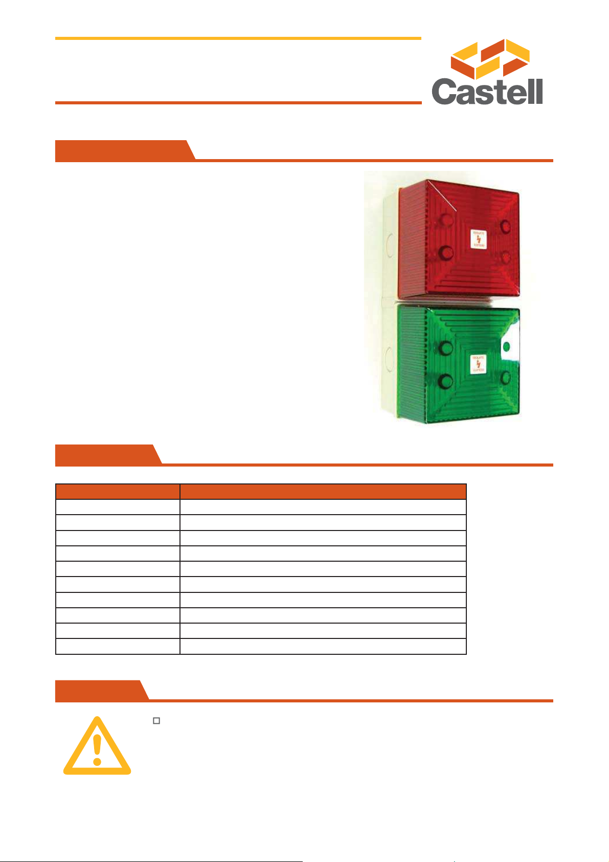
Product Code: 006538
Salvo TrafÞ c Lights are a means of communicating the
status of the loading bay door.
The lights can be mounted inside, outside or on both sides
of the loading bay.
When mounted inside, a red light indicates that the bay door
cannot be opened. A green light indicates that the door can
be opened and loading or unloading commenced.
When mounted outside, a red light indicates that the
door is open the the vehicle must not drive away. A green
light indicates that the door is closed and the vehicle can
depart.
Installation should be carried out by a qualiÞ ed electrician. Please retain this
document.
Specifi cations
Precautions
Description Specifi cation
Dimensions 180mm (h) x 90mm (w) x 81mm (d)
Termination 2.5mm² in and out
Cable Entries 1 x 5-7mm push through grommet
Mounting Surface
Housing/Lens PC (Flame Retardant)
IP Rating IP65
Temp. Range -20°C - +40°C
Light Source High Output LED
Light Output 12 x LED Array
Voltage 24VDC

Step 01: All units are supplied separate from the back box. The back box must be mounted with
the two cable entries at the top or bottom.
Step 02: 20mm cable entries are provided on all sides and in the base. The back box should be
mounted to a suitable surface or to a standard wiring box, using any of the mounting holes.
Step 03: The supplied gasket should be used if the surface is uneven or if the unit is to be used
in wet conditions.
Step 04: To remove the required knockout, the box should be turned on its face. A 6mm screw
driver blade should be placed in the knockout recess and given a sharp tap. The plastic will break
away cleanly.
Step 05: Connect the power supply to the appropriate terminals (see Salvo Control Panel).
Step 06: Earth continuity of cable sheath or conduit may be maintained by Þ tting earth tags to the
entry Þ ttings and linking them together inside the back box.
Step 07: The installation is completed by Þ tting the beacon onto the back box by means of the
supplied screws.
Step 08: The terminals will accept wires of I4-18AWG. Use the duplicated terminals to route the
in and out wires through the system loop.
Issue 1. April 2008
50
Installation
1
Salvo Traffi c Lights
User Guide
Wiring
2
Refer to SCP wiring schematic diagram on page 29.
 Loading...