

Cass Technology CASTLE S SERIES, CASTLE-2S, CASTLE-4S, CASTLE-8S Technical Operation Manual
Page 1

CASTLE S SERIES CONTROLLER – TECHNICAL OPERATION GUIDE
CASS TECHNOLOGY SDN BHD(338857-X) 1
TECHNICAL
OPERATION GUIDE
CASTLE S SERIES ACCESS SYSTEM
Page 2

CASTLE S SERIES CONTROLLER – TECHNICAL OPERATION GUIDE
Disclaimer
©2004 Cass Technology Sdn Bhd, All Right Reserved.
Information of this documentation is subject to change/modification without any notification.
The names of companies, products, people, characters, and/ or data mentioned herein are
fictitious and are in no way intended to represent any real individual, company, product, or
event, unless stated.
Cass Technology may have patents, patent application, trademarks, copyrights, or other
intellectual property rights covering subject matter in this documentation. No part of this
publication may be reproduced, transcribed, transmitted, stored in retrieval systems or
translated into any languages in any form or by means without the written authorization
from Cass Technology Sdn Bhd. To obtain this permission, kindly contact/ write to the
attention of Cass Technology Sdn Bhd at:
CASS TECHNOLOGY SDN BHD
No. 28 Jalan PJU 3/48, PJU 3
Sunway Damansara Technology Park,
48710 Petaling Jaya,
Selangor Darul Ehsan, Malaysia.
Customer Support
Phone: +603 7803 0011
Fax: +603-7803 0066
Email: support@castle.com.my
CASS TECHNOLOGY SDN BHD(338857-X) 2
Page 3

CASTLE S SERIES CONTROLLER – TECHNICAL OPERATION GUIDE
TABLE OF CONTENT
CHAPTER 1 - COMPONENTS.......................................................................................................................... 4
SYSTEM CONFIGURATION ....................................................................................................................................... 5
CHAPTER 2 - OPERATION OVERVIEW..................................................................................................... 6
ACCESS CARD ..................................................................................................................................................... 6
ACCESS GRANTING ............................................................................................................................................... 6
SPECIAL PURPOSE TIME ZONE................................................................................................................................. 7
CHAPTER 3 - PROGRAMMING THE CONTROLLER............................................................................... 8
PROGRAMMING MENU STRUCTURE.......................................................................................................................... 8
KEY FUNCTIONS IN PROGRAMMING MODE..............................................................................................................11
ENTERING PROGRAMMING MODE............................................................................................................................11
CHAPTER 4 – SYSTEM MENU...................................................................................................................... 13
SETTING DATE AND TIME.................................................................................................................................... ..13
DOOR SETTING................. ................................................................................................................................14
SETTING HOLIDAYS.......... ................................................................................................................................ 19
SETTING TIMERSET.............................................................................................................................................. 20
SETTING TIME ZONE ............................................................................................................................................22
ACCESS LEVEL ....................................................................................................................................................23
PARAMETERS...................................................................................................................................................... 24
CHAPTER 5 – DATABASE MENU................................................................................................................. 25
INSTALLING CARD ............................................................................................................................................. .. 25
DELETE CARD ................................................................................................................................................. ... 26
VIEW CARD DATABASE ........................................................................................................................................27
VIEW LOG TRANSACTION ..................................................................................................................................... 28
CLEAR CARD DATABASE ...................................................................................................................................... 29
RESET ANTI-PASSBACK FLAG ............................................................................................................................... 29
RESET LOCK OUT FLAG .......................................................................................................................................29
CHAPTER 6 – GENERAL PURPOSE OUTPUT...........................................................................................30
CHAPTER 7 – SENSOR.................................................................................................................................... 31
ARMING THE SENSOR ........................................................................................................................................... 31
ARMING TIMEZONE .............................................................................................................................................31
CHAPTER 8 – MAINTENANCE MENU........................................................................................................ 32
CHANGING PASSWORD...........................................................................................................................................34
SET STRING................................................................................................................................................ .........35
TESTING............................................................................................................................................................ 35
Test Keypad.................................................................................................................................................. 36
Test Watch Dog.............................................................................................................................................36
Test Input...................................................................................................................................................... 36
Test Output................................................................................................................................................... 36
Readers Status.............................................................................................................................................. 37
CHAPTER 9 – PRINTER.................................................................................................................................. 38
CHAPTER 10 – INFORMATION.................................................................................................................... 39
CHAPTER 11 – CASTLE-S READER.............................................................................................................40
PROGRAMMING DURING EMERGENCY MODE AT THE READER...................................................................................40
Chane Card PIN ..............................................................................................................................................41
Duress Alarm ..................................................................................................................................................41
Card Reader LED Indicators ..........................................................................................................................41
APPENDIX -Wiring Diagram..........................................................................................................................42
CASS TECHNOLOGY SDN BHD(338857-X) 3
Page 4

CASTLE S SERIES CONTROLLER – TECHNICAL OPERATION GUIDE
Chapter 1-COMPONENTS
System Configuration
Below are the basic system configurations of the CASTLE-S Card Access System. The system is
typically built from a few basic components, these are:
a. CASTLE-S Controller
b. Card Readers
c. Electric Door Lock
d. Door Sensors
e. Auxiliary Alarm Inputs and Outputs
f. Exit Push Button
g. Power Supply
h. PC Interfacing Unit
i. Online Parallel Printer (Available for Car Park Access)
a. CASTLE-S (2S, 4S, 8S) Controller
The CASTLE-S controller is normally referred to as ''The Controller''. This is the most important
component of the system. It houses the Central Processing Unit (CPU) and performs all the
control and validation functions.
The Controller has a Liquid Crystal Display (LCD) capable of showing 2 lines of 20 characters
each. The user can interacts with the Controller by means of a keypad, that simply a 16-key
keypad.
b. Card Reader
The Card Reader is a reading device for the access cards. The Card Reader reads the data
encoded on the access cards and sends it to the Controller for processing via a 2-wire RS485
links.
The keypad is provided to the user to key in their Personal Identification Number (PIN). This
gives added security to the system.
Depending on the applications, card readers can be used to control doors with Anti-Passback.
c. Electric Door Lock
The electric door lock is an electromagnetic device for locking and unlocking the door. When
the door lock is activated, the door released and the door can be opened; when the locked is
deactivated, the door lock is locked and the door can not be opened.
The door lock is directly wired to the reader.
Depending on the type of the door and the level of the security, the user can select from the
different types of electric door locks, such as
a. Electric Door Latch
b. Magnetic Lock
c. Drop Bolt
CASS TECHNOLOGY SDN BHD(338857-X) 4
Page 5

CASTLE S SERIES CONTROLLER – TECHNICAL OPERATION GUIDE
d. Door Sensor
The door sensor is use for detecting whether the door is closed or opened. The door sensor is
linked to the reader.
e. Alarm Inputs and General Purpose Outputs
The controller has built-in alarm system with four digital inputs, one relay alarm output and one
general-purpose output. The user can make use of these inputs to monitor other alarm points.
f. Exit Push Button
The user can choose to press a button to exit the protected area. This exit push button is
installed inside the protected area. The user merely presses the button to exit.
g. Power supply
The CASTLE-S Card Access System operates from a 12 VDC supply with a battery backup.
Typical power consumption is 12 VDC, 350mA.
h. PC Interfacing Unit
You can link the CASTLE-S Controllers to a Personal Computer for total system control by the
PC. The PC software allows you to perform a wide range of supervisory and control from your
computer. The CASTLE-S PC software is running under Windows95 or higher and requires
Pentium166MHz 32 RAM or better computer.
CASS TECHNOLOGY SDN BHD(338857-X) 5
Page 6

CASTLE S SERIES CONTROLLER – TECHNICAL OPERATION GUIDE
Chapter 2 - Operation Overview
Access Card
Each user of the Castle-S Card Access System is issued with an access card.
An access card is encoded with the following information:
a. User Card Number
b. Facility Code Number
The User Card Number is a 6-digit number that uniquely identifies each card holder.
The facility code is a 4-digit number. This number is used to differentiate the various installation
sites of the Castle-S Card Access System.
The Personal Identification Number is a 4-digit number. This PIN code feature provides a higher
level security by requiring the cardholder to swipe the card and to enter the PIN code to open the
door. The Castle-S can be programmed to operate in CARD ONLY Mode or CARD + PIN Mode.
Access Granting
When the user swipes the card on the card reader, the reader will send the card information to the
controller. The controller then decides whether to ‘activate’ the electric door or to reject the card. To
be granted access, the user card number must be in the controller in controller database. It must be
within a valid Time Zone for the card to be accepted.
Typically flow of access granting process:
The flow will stop once the card is rejected.
1. The user swipes his/her card on the reader. Is the card information OK?
If No, then reject.
If Yes, then continue.
2. Is the card number is installed?
If No, then reject.
If Yes, then continue.
3. Is the card allowed to access at that time (Valid time Zone)?
If No, then reject.
If Yes, then continue.
4. Is Card + Pin Mode Enable at that time?
If No, then the Door is unlock (end of flow).
If Yes, then the user has to key in his/her Pin number.
4.1 Is Pin Number correct?
If No, then reject.
If Yes, then the Door is unlock.
CASS TECHNOLOGY SDN BHD(338857-X) 6
Page 7

CASTLE S SERIES CONTROLLER – TECHNICAL OPERATION GUIDE
Special Purpose Time Zone
CASTLE-S has special TimeZone, namely:
a. Door #1 to Door #8 Auto Lock Release TimeZone
b. Door #1 to Door #8 Local PIN Mode TimeZone
c. Door #1 to Door #8 Card + PIN Mode TimeZone
d. Pin Mode TimeZone
e. General Purpose Output TimeZone
f. Sensor / Alarm Arm TimeZone
a. Door #1 to Door #8 Auto Lock Release TimeZone
The Automatic Lock Release Time Zone can be programmed to lock or unlock the electric door
for certain time periods. One of these features is to unlock the office main door during office
hours. After office hours, the door will be locked and users will need to swipe their cards to
enter the office.
b. Door #1 to Door #8 Local PIN Mode Time Zone
Each door (Door #1 to Door #8) can be set to its own PIN number separately. There are two sets
of PIN number to be set into each reader. The Local PIN Mode Time Zone is used to specify the
time periods when the user will need to enter the PIN number for the specify door to access the
door. Outside the PIN Mode TimeZone, the user will not allowed to use the PIN to enter the
premises.
c. Door #1 to Door #8 Card + PIN Mode TimeZone
The Card + PIN Mode TimeZone is used to specify the time periods when the users will need to
swipe their cards AND enter the PIN numbers. Outside the CARD + PIN Mode TimeZone, the
user will only need to swipe their card to gain entry. PIN entry is not required.
d. PIN Mode TimeZone
This is a Common PIN number set in the controller. All the readers are sharing this PIN number.
The PIN Mode TimeZone is used to specify the time periods when the user can enter the secure
area by entering a PIN number. Outside the PIN Mode TimeZone, the user will not allowed to
use the PIN to enter the premises.
e. General Purpose Output TimeZone
This is a relay output that can be used for general purposes. It can be used for controlling the
lighting or ventilation systems. It can be turned ON/OFF manually or by TimeZone controlled
(Use an external relay with higher ampere).
f. Sensor / Alarm Arm TimeZone
Sensor / Alarm Arm TimeZone is used to automatically arm and disarm the alarm system. This
feature is useful for automatically arming the alarm system after office hours and disarming
during office hours. Manual arming and disarming is also possible by entering a 6-digit
arming/disarming password at the readers.
CASS TECHNOLOGY SDN BHD(338857-X) 7
Page 8
CASTLE S SERIES CONTROLLER – TECHNICAL OPERATION GUIDE
Chapter 3 - Programming The Controller
This section is explaining the CASTLE-S programming environment. The CASTLE-S controller
uses the LCD and keypad during the programming mode.
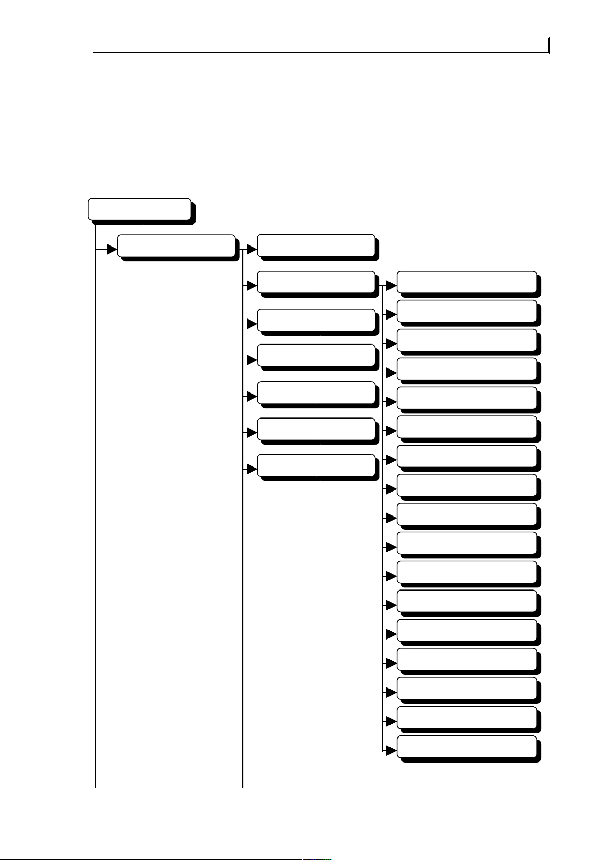
Programming Menu Structure
CASS TECHNOLOGY SDN BHD(338857-X) 8
Main Menu
System
Date and Time
Door
Lock Release Time
Door Open Time
In Location Code
Out Location Code
Emergency PIN
Auto-Lock Release TZ
Card + PIN TimeZone
Emergency Mode
Use Common PIN
Local PIN 1
Local PIN 1 TimeZone
Local PIN 2
Local PIN 2 TimeZone
Holidays
Timers
Time Zones
Access Level
Clear Memory
Security
PIN Mode
Card + PIN Mode
Master
Page 9
CASTLE S SERIES CONTROLLER – TECHNICAL OPERATION GUIDE
CASS TECHNOLOGY SDN BHD(338857-X) 9
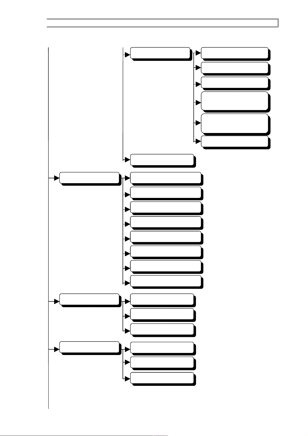
Parameters
Lock Out
Check Expiry
Anti-Passback
Auto-PIN 1 to
Auto-PIN 10
Auto-PIN 1 to
Auto-PIN 10 TimeZone
Facility Code
Return to Main Menu
Return to Main Menu
Database
Install Card
Delete Card
View Card Database
View Log Transaction
Clear Card Database
Reset Anti-Passback
Return to Main Menu
Reset PIN Lock Out Flag
Gen Purpose Output
Select ON/OFF
Out Put TimeZone
Return to Main Menu
Sensor
Arming
Arming TimeZone
Page 10
CASTLE S SERIES CONTROLLER – TECHNICAL OPERATION GUIDE
CASS TECHNOLOGY SDN BHD(338857-X) 10
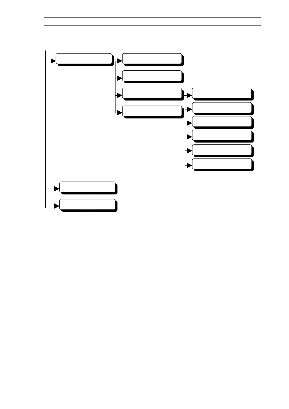
Maintenance
Change Password
Set String
Test
Test Keypad
Test WatchDog
Test Input
Test Output
Return to Main Menu
Return to Main Menu
Info
Quit Menu
Reader Status
Page 11

CASTLE S SERIES CONTROLLER – TECHNICAL OPERATION GUIDE
Key Functions in Programming Mode
The '0' to '9' keys are used for entering numbers as well as alphabets. The 'A', 'B', 'C', 'D', 'ENT' and
'ESC' keys are function key. Their usage is described in the following table.
Key Usage
A Scroll Menu to Left
B Select Menu Item on the Left
C Select Menu Item on the Right
D Scroll Menu to Right
ENT Accept data entry
ESC Abort/Backspace
Once in the programming, choose the appropriate menu item by pressing in the corresponding
number or use the 'B' or 'C' key as describe above.
Entering Programming Mode
To enter into the programming mode, press any key at the keypad. The backlit of the LCD will be
turned ON (this is to indicate programming mode) and the LCD will show:
Where dd/mm – current date; DDD – day of week; hh:mm:ss – current time
Enter the 6 digits password. There are three levels of password.
The default passwords are:
1) Level 1 => 888888
2) Level 2 => 222222
3) Level 3 => 333333 (highest access level)
Level 1 password allows the user to only enter the Alarm Arm or Disarm Mode in the Programming
Menu Structure.
Level 2 password allows the user to enter the view database ,testing / maintenance and purposes
menu items.
Level 3 Password allows user to access all the remaining items in the Programming Menu Structure.
All the password above can be changed via the Maintenance/Change Password Menu. If the user use
level 1 password, the user only can change Alarm Arm / Disarm passwords only, then follow by the
rest the same method.
CASS TECHNOLOGY SDN BHD(338857-X) 11
dd/mm DDD hh:mm:ss
Password [ ]
Page 12

CASTLE S SERIES CONTROLLER – TECHNICAL OPERATION GUIDE
CASS TECHNOLOGY SDN BHD(338857-X) 12
Page 13
CASTLE S SERIES CONTROLLER – TECHNICAL OPERATION GUIDE
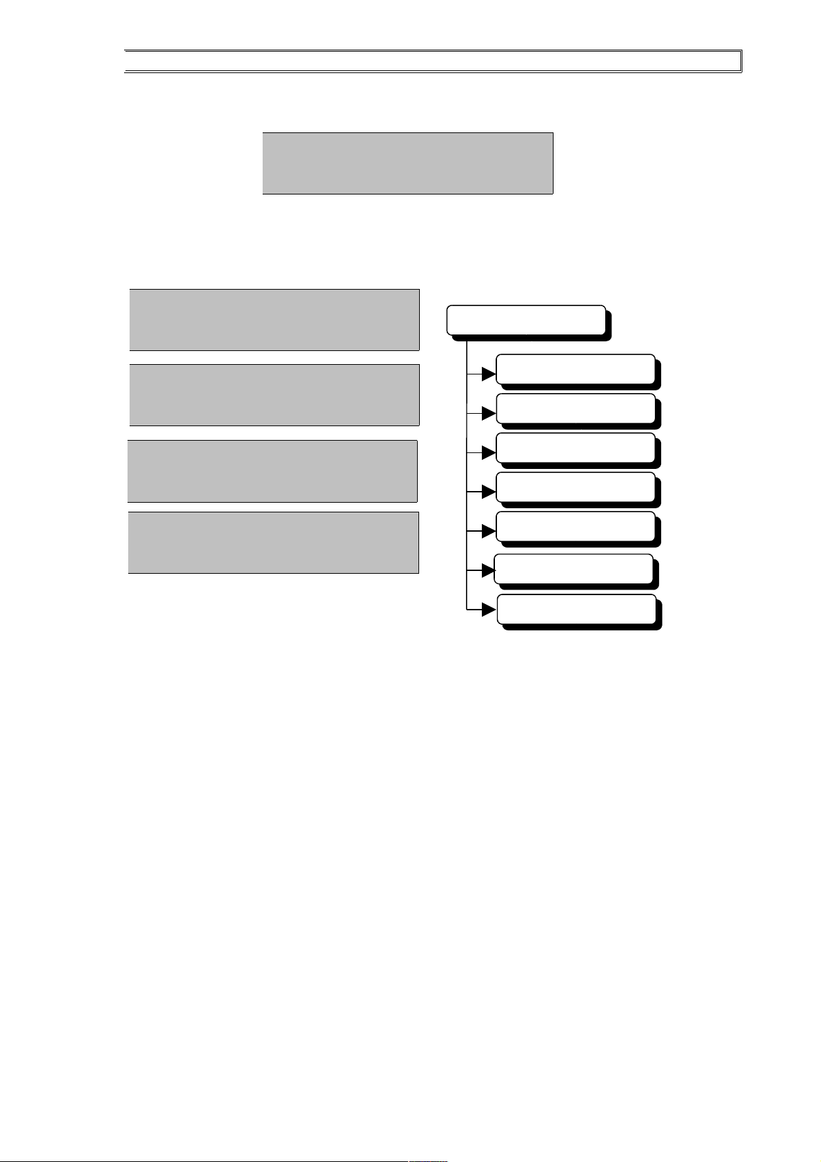
After keying the password, the Main Programming Menu will be shown on the LCD.
Use the ‘A’ and ‘D’ keys to scroll the menu to left and right respectively. As you press the ‘D’ key,
the display will be changed.
CASS TECHNOLOGY SDN BHD(338857-X) 13
MAIN MENU
2. DBASE
3. GP OUTPUT
4. SENSOR
5. MAINTENANCE
6. INFO
1. SYSTEM
0. QUIT MENU
dd/mm DDD hh:mm:ss
1-System 2-DBase
dd/mm DDD hh:mm:ss
2-DBase 3-GP Op
dd/mm DDD hh:mm:ss
4-Sensor 5-Maint
dd/mm DDD hh:mm:ss
6-Info 0-Quit
dd/mm DDD hh:mm:ss
C8 v6-05
Page 14

CASTLE S SERIES CONTROLLER – TECHNICAL OPERATION GUIDE
Chapter 4 – System Menu
CASS TECHNOLOGY SDN BHD(338857-X) 14
System
Date and Time
Door
Lock Release Time
Door Open Time
In Location Code
Out Location Code
Emergency PIN
Auto-Lock Release TZ
Card + Pin TimeZone
Emergency Mode
Use Common PIN
Local PIN 1
Local PIN 1 TimeZone
Local PIN 2
Local PIN 2 TimeZone
Holidays
Timers
Time Zones
Access Level
Clear Memory
Parameters
Lock Out
Check Expiry
Anti-PassBack
Auto-PIN 1 to
Auto-PIN 10
Auto-PIN 1 to
Auto-PIN 10 TimeZone
Facility Code
Return to Main Menu
Security
PIN Mode
Card + PIN Mode
Master PIN
Page 15

CASTLE S SERIES CONTROLLER – TECHNICAL OPERATION GUIDE
Under the System Menu, the user can change the Date and Time, Door Setting, TimeSets,
TimeZones, Holidays, the system Parameters such as Facility Code, Auto-PIN number, Lock Out,
Anti-PassBack and so on.
To enter the System Menu, press the ‘1’ key from the Main Menu.
The following will be displayed.
Setting Date and Time
Press ‘1’ to select [1-Date] menu from the System Menu.
This menu item is for user to change the date and time setting on the system clock. When user select
this menu item, the controller will display the current date and time as the following figure: -
Digits in the ( ) bracket are under focus.
Use the ‘0’ to ‘9’ keys to change Year, Month and Date.
User can delete the previous key using ESC key on the keypad.
After user has changed Date, the LCD will change to: -
CASS TECHNOLOGY SDN BHD(338857-X) 15
dd/mm DDD hh:mm:ss
1-Date 2-Door
dd/mm DDD hh:mm:ss
2-Door 3-Holiday
dd/mm DDD hh:mm:ss
3-Holiday 4-Timers
dd/mm DDD hh:mm:ss
5-T Zone 6-Acc Lvl
dd/mm DDD hh:mm:ss
6-Acc Lvl 7-Clear
dd/mm DDD hh:mm:ss
4-Timers 5-T Zone
dd/mm DDD hh:mm:ss
7-Clear 8-Param
dd/mm DDD hh:mm:ss
8-Param 0-Quit
dd/mm DDD hh:mm:ss
Yr(1998) M[06] D[10]
Page 16
CASTLE S SERIES CONTROLLER – TECHNICAL OPERATION GUIDE
Digits in the ( ) bracket are under focus.
Proceed in the same way to change Hour and Minute. Once user has completed changing Minute, the
system clock will be updated.
Door Setting
Press ‘2’ to select [2-Door] menu from System Menu.
This menu item allows user to set the door setting. To set the specified door, user has to enter the
number of door (1-2 for 2s series, 1-4 for 4s series, 1-8 for 8s series). To set the other door, user has
to press the ‘2’ again at System Menu to enter to Door Setting Mode.
When the user select this menu item, the controller will step through each of the Door Setting. The
key usage under this menu is listed below: -
Key Function
0 – 9 Set the digit
ESC Skip the setting
ENT/D Accept the setting
For ON/OFF value entries, use the ‘0’ key to toggle the value.
a. Lock Release Time
A value of 00-15 is allowed. This value determines the amount of time (in seconds) that the
electric door-lock is activated after a valid user card has been swiped. If the door is not opened
within this time period, the door will be deactivated. The default value is 05 seconds.
b. Door Open Time
A value of 00-30 is allowed. This value determines the amount of time (in seconds) that the door
takes to close. If the door is left opened for longer than this time period, the buzzer would sound.
The default value is 10 seconds.
c. In Location Code
A value of 00-99 is allowed. This value determines the door In Location Code of the Door. This
setting will be used when the Anti-PassBack Mode at the Parameter Menu is ON.
CASS TECHNOLOGY SDN BHD(338857-X) 16
dd/mm DDD hh:mm:ss
Hr(09) MIN[54]
dd/mm DDD hh:mm:ss
Lock Rel Time [ 05 ]
dd/mm DDD hh:mm:ss
Door Open Time [ 10 ]
dd/mm DDD hh:mm:ss
In Loc Code [ 00 ]
Page 17

CASTLE S SERIES CONTROLLER – TECHNICAL OPERATION GUIDE
d. Out Location Code
A value of 00-99 is allowed. This value determines the door Out Location Code of the Door.
This setting will be used when the Anti-PassBack Mode at the Parameter Menu is ON.
Example setting of Anti-Passback: -
DOOR NO IN LOCATION OUT LOCATION
DOOR 1 01 02
DOOR 2 01 02
DOOR 3 02 03
DOOR 4 01 03
e. Emergency PIN
4 digits of number are required to set the emergency PIN. When the controller is down, user can
use this PIN number to access the door through the entry reader.
f. Auto-lock Release TimeZone
A value of 00-99 is allowed. This item is used to set the electric lock automatically released
within the TimeZone setting.
g. Card + PIN TimeZone
A value of 00-99 is allowed. This item is used to set the reader to prompt the card user for PIN
number after the user swipe a valid card. This option will be activated within the TimeZone
setting.
CASS TECHNOLOGY SDN BHD(338857-X) 17
In 01
In 01
In 02
In
01
Out
03
Out
02
Out
03
Out
02
2
3
1
dd/mm DDD hh:mm:ss
Out Loc Code [ 00 ]
DOOR 2
DOOR 1
DOOR 3
DOOR 4
dd/mm DDD hh:mm:ss
Emer Pin [ 0000 ]
dd/mm DDD hh:mm:ss
ALR Tz [ 00 ]
dd/mm DDD hh:mm:ss
Card + Pin Tz [00]
Page 18

CASTLE S SERIES CONTROLLER – TECHNICAL OPERATION GUIDE
h. Emergency Mode
A value of 1-3 is allowed. This setting can only be used when the controller is down. The reader
will follow the setting at the controller and will operate independently. The default value is set
to 1.
Below is the configuration setting of each number: -
Function
1 Lock Release
2 Facility Code
3 Auto-PIN
1 => The electric lock will automatically released when the controller is down.
2 => The reader will prompt user to swipe the card. It will release the lock when
the facility code of the card is valid.
3 => Only Auto-PIN that set at the Emergency PIN Mode in the Controller is
required.
i. Use Common PIN (Set the Common No. in Parameter Setting)
This item is used to set the reader to use the Auto-PIN number that set at the controller or use the
Local Auto-PIN number that to the specify door. This only can be set to ON or OFF position.
j. Local PIN 1
4 digits of number are required to set the Local Auto-PIN number. This is only can be used at the
specify door and when the Use Common PIN Mode is OFF.
k. Local PIN 1 TimeZone
Set the TimeZone for the Local PIN 1, so that the Local Auto-PIN 1 can be used within the
TimeZone setting.
l. Local PIN 2
4 digits of number are required to set the Local Auto-PIN number. This is only can be used at the
specify door and when the Use Common PIN Mode is OFF.
CASS TECHNOLOGY SDN BHD(338857-X) 18
dd/mm DDD hh:mm:ss
Emergency Mode [ 3 ]
dd/mm DDD hh:mm:ss
Use Common Pin [ON]
dd/mm DDD hh:mm:ss
Local Pin 1 [0000]
dd/mm DDD hh:mm:ss
Local Pin 1 Tz [00]
dd/mm DDD hh:mm:ss
Local Pin 2 [0000]
Page 19

CASTLE S SERIES CONTROLLER – TECHNICAL OPERATION GUIDE
m. Local PIN 2 TimeZone
Set the TimeZone for the Local PIN 2, so that the Local Auto-PIN 2 can be used within the
TimeZone setting.
Example setting of Auto PIN Mode: -
PIN
MODE
USE
COMMON
COMMON
PIN (CP)
LOCAL
PIN (LP)
STATUS
ON YES Use CP (Tz) N/A CP activated with Tz
ON OFF N/A Local Pin LP activated
OFF YES N/A N/A Both deactivated
OFF NO N/A Local Pin (Tz) LP activated with Tz
n. Security
‘ON/OFF’ value. This option is used to enable or disable the security of the system.
When the Security Mode is ON, the reader will prompt the user for the Card, Card + PIN or
Auto-PIN to access the system; if the Security Mode is OFF, the electric lock will be released
and the door is always opened until the Security Mode is set to ON again.
o. PIN Mode
‘ON/OFF’ value. When the PIN Mode is set to ON, the user has to key in the Auto-PIN to access
the door; if it is set to OFF, the user will not be prompted to key in the Auto-PIN, but the user
can swipe his/her card to access the door.
p. Card + PIN Mode
‘ON/OFF’ value. When the Card + PIN Mode is set to ON, the user has to key in the Card PIN
after his/her card is valid. If it is set to OFF, depends on Card + PIN Mode TimeZone setting,
the user will not be prompted to key in the Card PIN, only swipe a valid card.
q. Master PIN
6 digits of number are required to set the MASTER PIN. This is used to enter the Programming
Mode at the reader when the controller is down. User can use this PIN number to program the
reader. (The programming steps are shown in Chapter 11)
CASS TECHNOLOGY SDN BHD(338857-X) 19
dd/mm DDD hh:mm:ss
Local Pin 2 Tz [00]
dd/mm DDD hh:mm:ss
Security [ON]
dd/mm DDD hh:mm:ss
Local Pin Mode [ON]
dd/mm DDD hh:mm:ss
Card + Pin Mode [ON]
dd/mm DDD hh:mm:ss
Master [000000]
Page 20

CASTLE S SERIES CONTROLLER – TECHNICAL OPERATION GUIDE
Setting Holidays
Press ‘3’ to select [3-Holiday] menu from the System Menu.
This menu item sets the Holidays database. There are two types of holidays, Holiday_1 and
Holiday_2. Holiday_1 is higher priority than Holiday_2. That’s mean Holiday_1 will be taken into
consideration by the controller rather than Holiday_2.
When user select this menu, controller will prompt the user to choose which type of holiday they
want.
The controller lets you enter up to 30 dates of holidays in each Holiday1 and Holiday2.
User has to press ‘1’ or ‘2’ to select Holiday_1 or Holiday_2.
After the selecting, the controller will display the first holiday date as in the following: -
MM => month
DD => day
Digits in the ( ) bracket are under focus.
Use the ‘0’ to ‘9’ keys and the ‘ENT’ to enter the month of the holiday followed by the day. Press
the ‘ENT’ key to accept the date and the display will show the next holiday date.
Continue until all the holidays have been entered. There are total of 30 holiday dates in each Holiday
setting, which can be entered. To clear a holiday, enter ‘00’ for both month and day entries.
CASS TECHNOLOGY SDN BHD(338857-X) 20
dd/mm DDD hh:mm:ss
Type ? (1/2) [ 1 ]
dd/mm DDD hh:mm:ss
Hol – 01 MM(00) DD[00]
Page 21

CASTLE S SERIES CONTROLLER – TECHNICAL OPERATION GUIDE
Setting TimerSet
TimeSet is the time period setting activation of an operation.
In cardholder database, you use TimeSet to specify the valid time periods for the card to access the
system.
For example:
You may specify the TimeSet for the office as follows:
TimeSet #2
Interval #1 08:00 to 12.30
Interval #2 13:30 to 18:00
Interval #3 00:00 to 00:00
This allows the office staff accesses the system from 8:00am to 12.30 noon and from 1.30pm to 6pm.
In other words, if the office staff accesses the system within these periods of time, he/she will be
granted access. If it is outside these periods of time, he/she will not be granted access.
The Castle-S provides 98 TimeSet for you to program with.
The TimeSet 00 and 01 is the pre-fixed TimeSet.
00 = no access time being set
01= from 00:00 to 23:59
The TimeSet Setting can only specify the access time period for a particular day. To specify the
access time period for different day, you may use the Time Zone Setting.
Time Zone Setting is made up of TimeSet. You specify 9 TimeSet in each TimeZone Setting (one
for each day of the week plus 2 holidays). By, specifying the Time Zone Setting of a card, the
controller can then automatically control the different accessibility of the card from Sunday to
Saturday an Holidays.
The example below shows the use of time zone and time set to control the accessibility of the card.
Example:
Time Set Sample :
TimeSet #00 TimeSet #01
Interval #1 00:00 to 00:00 Interval #1 00:00 to 23:59
Interval #2 00:00 to 00:00 Interval #2 00:00 to 00:00
Interval #3 00:00 to 00:00 Internal #3 00:00 to 00:00
TimeSet #02 TimeSet #03
Interval #1 08:00 to 12:30 Interval #1 08:00 to 12:00
Interval #2 13:30 to 18:00 Interval #2 15:00 to 18:00
Interval #3 00:00 to 00:00 Interval #3 00:00 to 00:00
TimeSet #04
Interval #1 08:00 to 13:30
Interval #2 00:00 to 00:00
Interval #3 00:00 to 00:00
CASS TECHNOLOGY SDN BHD(338857-X) 21
Page 22

CASTLE S SERIES CONTROLLER – TECHNICAL OPERATION GUIDE
Press ‘4’ to select [4-Timers] menu from the system menu.
This menu item sets the Timer database. When user select this menu item, controller will display the
following: -
There are 100 timers available. Timer_00 and Timer_01 are pre-fixed sets, cannot be changed. Only
from Timer_02 to timer_99 can be set by the user.
User can use ‘0’ to ‘9’ to select which Timer he/she wants to update.
For example: -
To select Timer_12, press ‘1’ follow by ‘2’, the LCD will display as follow: -
Digits in the ( ) bracket are under focus.
S
This display shows the start time and the end time for the Timer_12, Interval_1. Each set of timer
has 3 intervals of start and end times. They are used in conjunction with TimeZones.
Use ‘0’ to ‘9’ keys to enter the start time and the end time. Repeat the step to proceed to Interval_2
and Interval_3. To clear the interval, set the start and end time to ‘0000’.
CASS TECHNOLOGY SDN BHD(338857-X) 22
dd/mm DDD hh:mm:ss
TimeSet No ? [01]
dd/mm DDD hh:mm:ss
I1(0000) - [0000]
Page 23

CASTLE S SERIES CONTROLLER – TECHNICAL OPERATION GUIDE
Setting Time Zone
Time Zone # SUN MON TUE WED THU FRI SAT HOL1 HOL2
Time Zone #01
01 01 01 01 01 01 01 01 01
Time Zone #02
00 02 02 02 02 03 04 00 00
Time Zone #03
00 02 00 02 00 02 00 00 00
Each entry in the Time Zone setting above refers to the TimeSet no.
In the table above,
a. The Time Zone #01 specifies that the card will use TimeSet #01 everyday where TimeSet #01 is
00:00 to 23:59 (24 hours access).
b. The Time Zone #02 specifies that the card will use TimeSet #00 on Sunday and Holidays (non-
access at all), TimeSet #02 on Monday till Thursday (08:00 to 12:30, 13:30 to 18:00), TimeSet
#03 on Friday (08:00 to 12:00, 15:00 to 18:00) an TimeSet #04 on Saturday (08:00 to 13:30).
c. The Time Zone #03 specifies that the card will use TimeSet #00 on Sunday, Tuesday, Thursday,
Saturday and both two holidays (non-access at all) and TimeSet #02 on Monday, Wednesday
and Friday.
Typically you can assigned the card of
a. Manager/director with TimeZone #01,
b. Normal staff with TimeZone #02 and
c. Cleaners with TimeZone #03.
Since the Castle-S controller controls 8 doors, you need to specify the TimeZone Setting of a card
for each door.
Press ‘5’ to select [5-Tzone] menu from System Menu.
This menu item sets the TimeZone database. When user select this menu item, controller will display
the following: -
There are 100 time zones available. TimeZone_00 and TimeZone_01 are pre-fixed sets, cannot be
changed. Only from TimeZone_02 to timeZone_99 can be set by the user.
User can use ‘0’ to ‘9’ to select which TimeZone he/she wants to update.
For example: -
To select TimeZone_11, press ‘1’ for twice, the LCD will display as follow: -
This display shows the Timer_01 to be used on Sunday for TimeZone_11. User can change the timer by using
‘0’ to ‘9’ keys or accept without changes by pressing the ‘ENT’ key. To clear the Timer, set the Timer to ‘00’.
Repeat the step to proceed to MON, TUE, WED, THU, FRI, SAT, HOL_1 AND HOL_2.
CASS TECHNOLOGY SDN BHD(338857-X) 23
dd/mm DDD hh:mm:ss
TimeZone No ? [01]
dd/mm DDD hh:mm:ss
Sun TimeSet [01]
Page 24

CASTLE S SERIES CONTROLLER – TECHNICAL OPERATION GUIDE
Access Level
Press ‘6’ to select [6-Acc Lvl] menu from System Menu.
This menu item sets the Access Level for the card user.
When user select this menu item, controller will display the following: -
There is 100 Access Level setting. AccessLevel_00 and AccessLevel_01 are pre-fixed sets, cannot
be changed. Only from AccessLevel_02 to AccessLevel_99 can be set by the user.
User can use ‘0’ to ‘9’ to select which Access Level he/she wants to update.
For example: -
To set the AcessLevel_77, press ‘7’ for twice, the LCD will display as follow: -
dd => day mm => month
yyyy => year
After that it will prompt the user to enter the data. The display as following: -
Digits in the ( ) bracket are under focus.
This is the start of the Expiry Date setting. The earliest Start Date is 01/01/1998.
After keying the Start Date, the display will be changed as following: -
Digits in the ( ) bracket are under focus.
This is the end of the Expiry Date setting. The latest End Date is 31/12/2030.
After keying the End Date, the display will be changed as following: -
00-99 is available. This option lets user to set the TimeZone for the card user. The card user only can
access the door within the TimeZone.
Repeat the step to proceed to Door_2_TZ (2s), Door_4_TZ (4s) or Door_8_TZ (8s).
Access Level Door 1 (Tz) Door 2 (Tz) Door 3 (Tz) Door 4 (Tz)
Default 00 00 00 00 00
Default 01 01 01 01 01
02 01 02 00 00
03 02 00 00 00
04 03 03 03 03
CASS TECHNOLOGY SDN BHD(338857-X) 24
dd/mm DDD hh:mm:ss
Acc Lvl No ? [01]
dd/mm DDD hh:mm:ss
Date in dd/mm/yyyy
dd/mm DDD hh:mm:ss
St (00) / [00] / [0000]
dd/mm DDD hh:mm:ss
Ed (00) / [00] / [0000]
dd/mm DDD hh:mm:ss
Door 1 Tz ( )
Page 25

CASTLE S SERIES CONTROLLER – TECHNICAL OPERATION GUIDE
Parameters
Press ‘8’ to select [8.Param] menu from the System Menu.
This menu item sets the controller System Parameter. When user select this menu, the controller will
step through each of the System Parameters.
The System Parameters are listed as below: -
a. Card Lock-Out Mode
‘ON’ / ‘OFF’ value. When this option is set, the card user will only be allowed 3 invalid access
attempts (Card & Pin Mode and Anti-Passback) after the user will be locked out from the
system. Access will need to be manually granted. User cards that have been locked out can only
be used again after resetting the Lock Out Flag. This is described in the DBASE Menu.
b. Check Expiry
‘ON’ / ‘OFF’ value. When this option is set, the system will check the Expiry Date Setting of the
card that set at the Access Level. The system will not allow the card user to access the door
when the card is EXPIRED.
c. Anti-Passback
‘ON’ / ‘OFF’ value. Anti-Passback is to ensure that if the person swipes at the IN-Reader of the
door to go into the protected area, he/she must swipes at the OUT-Reader of the door to go out
from the protected area. After he/she has swiped out of the protected are, the next valid swipe is
only at the In-Reader of the door.
d. Auto-PIN1 to Auto-PIN10 (Common PIN Setting)
4 digits of number are required to set the Auto-PIN numbers. There is 10 PIN numbers to be set.
All the readers can share these PIN numbers. But the door must set the ‘Use Common PIN
Mode’ to ‘ON’ position.
To disable the PIN number, user can set the PIN number to ‘0000’ or set the PIN TimeZone to
‘00’ (this is describe as below).
e. Auto-PIN1 TimeZone to Auto-PIN10 TimeZone
Set the TimeZone for each Auto-PIN, so that each Auto-PIN can be used within the TimeZone
setting.
To disable the PIN number, user can set the PIN TimeZone to ‘00’.
f. Facility Code
A value of 0000-9999 is allowed. If ‘0000’ is entered, the controller will ignore the facility code
encoded in the user cards. Otherwise, only user cards with the set facility code will be accepted.
The default value is ‘0000’.
CASS TECHNOLOGY SDN BHD(338857-X) 25
Page 26

CASTLE S SERIES CONTROLLER – TECHNICAL OPERATION GUIDE
Chapter 5 – Database Menu
Under the database Menu, the user can install and delete user cards, view the Card Database and Log
Transactions, and reset Anti-Passback Flag and Card LockOut Flag.
To enter the Database Menu, press the ‘2’ key at Main Menu. The following will be displayed: -
Press ‘A’ to scroll the menu to left and ‘D’ to scroll the menu to the right.
As you press the ‘D’ key, the display will be changed to: -
CASS TECHNOLOGY SDN BHD(338857-X) 26
Database
Delete Card
Clear Card Database
View Card Database
View Log Transaction
Reset Anti-Passback Flag
Reset Lockout Flag
Install Card
Return to Main Menu
dd/mm DDD hh:mm:ss
1-Install 2-Delete
dd/mm DDD hh:mm:ss
2-Delete 3-View DB
dd/mm DDD hh:mm:ss
3-View DB 4-View LG
dd/mm DDD hh:mm:ss
4-View LG 5-Clr DB
Page 27

CASTLE S SERIES CONTROLLER – TECHNICAL OPERATION GUIDE
Installing Card
Press ‘1’ to select [1-Install] menu from Database Menu.
This menu item is to install cards. When user select this menu item, controller will display the
following: -
Enter the starting card numbers that want to be installed.
For example: -
The card number ‘123456’ is to be installed. Press number of the card number using the keypad. The
LCD display will then display: -
If the user wants to install 1 card, he/she just has to press the ‘ENT’ key to accept and go to next
mode. If the user wants to install 50 cards from 123456, he/she has to add up 123456 with 50, that is
123506. Then he/she just keys in the number 123506 into the End Number.
After that, the LCD display will then display: -
This is where the Access Level of the card is set.
If the user wants to change the Access Level of the card that already installed, he/she just can reinstall the card and select an Access Level again for the card.
CASS TECHNOLOGY SDN BHD(338857-X) 27
dd/mm DDD hh:mm:ss
5-Clr DB 6-Rst A/p
dd/mm DDD hh:mm:ss
6-Rst A/p 7-Rst L/o
dd/mm DDD hh:mm:ss
7-Rst L/o 0-Main
dd/mm DDD hh:mm:ss
Start [000000]
dd/mm DDD hh:mm:ss
End [123456]
dd/mm DDD hh:mm:ss
Acclvl [01]
Page 28

CASTLE S SERIES CONTROLLER – TECHNICAL OPERATION GUIDE
Delete Card
Press ‘2’ to select [2-Delete] menu from Database Menu.
This menu item is to delete user card one by one. When user select this menu item, the controller
will display the following: -
Key in the numbers of the card that wants to be deleted.
View Card Database
Press ‘3’ to select [3-View DB] menu from Database Menu.
This menu item is to view the contents of the card database. When user select this menu item, the
controller will display the following: -
If the user knows where is the card is installed, he/she just has to key in the digit ‘1’ to ‘4’ to select
the page number to view the card info. To view another card, he/she just has to press ‘D’ key to
select next card info; ‘A’ is for previous card info. To exit, press the ‘ESC’ key.
If the user want to search the card faster, he/she just key in any digit ‘1’ to ‘4’ then presses ‘ENT’.
The controller will then display as following: -
Key in the number of the card. Then the controller will search the card for the user. If the card is
installed in the controller, the controller will display the card info as follow: -
For example card ‘123456’ is found: -
123456 => card number
ALVL => Access Level of the card
CASS TECHNOLOGY SDN BHD(338857-X) 28
dd/mm DDD hh:mm:ss
Card #[000000]
dd/mm DDD hh:mm:ss
Page (1-4) ? [1]
dd/mm DDD hh:mm:ss
Find [000000]
dd/mm DDD hh:mm:ss
123456 ALVL01
Page 29

CASTLE S SERIES CONTROLLER – TECHNICAL OPERATION GUIDE
View Log Transaction
Press ‘4’ to select [4-View Lg] menu from Database Menu.
This menu item is to view the transactions logged. Use ‘A’ and ‘D’ keys to scroll through the
transaction log. To exit, press the ‘ESC’ key.
The Following Table Lists the Transaction Codes:
Description Transaction Code
Valid Entry Access 0
Anti-Passback Violation 1
Unknown Card Number 2
Wrong Facility Code 3
Reader Reset 4
Reader Up 5
Reader Down 6
Controller Reset 7
Enter Program Mode 8
Exit Program Mode 9
Memory Cleared A
Reset Anti-Passback B
Manual Lock Release C
Wrong PIN Password D
Door Left Open E
Door Closed F
Door Forced Open G
Card Lock Out H
Reset Lock Out I
Wrong Time Zone J
Duress Alarm K
Door Interlocked L
Alarm ON M
Alarm OFF N
Description Transaction Code
Door Security O
Alarm Delay Arm Start P
Alarm Armed Q
Alarm Trigger R
Alarm Disarm S
Alarm Isolated T
Output ON U
Output OFF V
Output Isolated W
Input ON X
Input OFF Y
Change PIN Z
Valid PIN Access a
Card Disable b
Card Enable c
Pulse Door Open d
Door Open e
Invalid PIN Access f
Inactive Card g
Card Expired h
Valid Exit Access i
Cold Start j
Door Security ON k
Door Security OFF l
CASS TECHNOLOGY SDN BHD(338857-X) 29
Page 30

CASTLE S SERIES CONTROLLER – TECHNICAL OPERATION GUIDE
Clear Card Database
Press ‘5’ to select [5-Clr DB] menu from Database Menu.
This menu item it to delete all the cards installed in the controller.
After press ‘5’ at Database Menu, the controller will display as follow: -
The controller will prompt the user to confirm to clear the card database. If the user confirm
to clear the database, he/she just has to press ‘ENT’ key. The controller will clear all the
database in the controller.
To cancel ‘Clear Card Database’, press ‘ESC’ key.
Reset Anti-Passback Flag
Press ‘6’ to select [6-Rst A/p] menu from Database Menu.
This menu item is to clear the Anti-Passback flag. User cards with the Anti-Passback flag set
cannot access the system. These cards can be reset by clearing the Anti-Passback flag.
After press ‘6’ at Database Menu, the controller will display as follow: -
Reset Lock Out Flag
Press ‘7’ to select [7-Rst L/o] menu from Database Menu.
This menu is to clear the lock out flag. User cards with the lock out flag set cannot access the
system. These cards can be reset by clearing the lock out flag.
After press ‘7’ at Database Menu, the controller will display as follow: -
Return to Main Menu
Press ‘0’ to select [0-Main] menu from Database Menu to return to Main Menu.
CASS TECHNOLOGY SDN BHD(338857-X) 30
dd/mm DDD hh:mm:ss
Clear Card (Y=ENT) ?
dd/mm DDD hh:mm:ss
Rst A/p (Y=ENT) ?
dd/mm DDD hh:mm:ss
Rst L/o (Y=ENT) ?
Page 31

CASTLE S SERIES CONTROLLER – TECHNICAL OPERATION GUIDE
Chapter 6 – General Purpose Output
Under General Purpose Output Menu, user can manually switch ON or OFF the Output and
set the TimeZone for the Output.
To enter this menu, press the ‘3’ key at Main Menu.
The following will be displayed: -
Output ON/OFF Switch
Press ‘1’ to select [1-ON/OFF] menu from General Purpose Output Menu.
This menu item is to manually switch ON/OFF the General Purpose Output.
When choosing this menu, the controller will display as follow: -
Press ‘0’ to select ‘ON’ or ‘OFF’ value.
Output TimeZone
Press ‘2’ to select [2-Op Tz] menu from General Purpose Output Menu.
This menu item is to set the TimeZone for the General Purpose Output.
When choosing this menu, the controller will display as follow: -
‘00’ to ‘99’is available. The output will automatically switch ON during the TimeZone.
Return to Main Menu
Press ‘0’ to select [0-Main] menu from General Purpose Output Menu to return to Main
Menu.
CASS TECHNOLOGY SDN BHD(338857-X) 31
General Purpose Output
Select ON/OFF
Output TimeZone
Return to Main Menu
dd/mm DDD hh:mm:ss
1-On / Off 2-Op Tz
dd/mm DDD hh:mm:ss
2-Op Tz 0-Main
dd/mm DDD hh:mm:ss
Output [OFF]
dd/mm DDD hh:mm:ss
Output TZ [00]
Page 32

CASTLE S SERIES CONTROLLER – TECHNICAL OPERATION GUIDE
Chapter 7 – Sensor
Under Sensor menu, user can manually arm the sensor and set the TimeZone for the sensor
arming.
To enter this menu, press the ‘4’ key at the Main Menu.
The following will be displayed: -
Arming the Sensor
Press ‘1’ to select [1-Arm] menu from Sensor Menu.
This menu item is to manually Arm the sensor by the user.
When choosing this menu, the controller will display as follow: -
Press ‘0’ to select ‘ON’ or ‘OFF’ value.
If the user switch the Sensor to ON position, the controller will display as in the following: -
Value 00 to 60 is allowed. The value indicates the time in seconds. This is the time delay for
the sensor starts arming.
CASS TECHNOLOGY SDN BHD(338857-X) 32
Sensor
Arming
Arming TimeZone
Return to Main Menu
dd/mm DDD hh:mm:ss
1-Arm 2-Arm Tz
dd/mm DDD hh:mm:ss
2-Arm Tz 0-Main
dd/mm DDD hh:mm:ss
Local Alarm [OFF]
dd/mm DDD hh:mm:ss
Local Arm Dly [00]
Page 33

CASTLE S SERIES CONTROLLER – TECHNICAL OPERATION GUIDE
After the user set the time, the controller will display as in the following: -
Value 00 to 60 is allowed. The value indicates the time in seconds. This is the time delay for
the relay triggers the alarm. Within this time period, the user has to disarm the Sensor
Arming, else it will sound the buzzer or silence.
Arming TimeZone
Press ‘2’ to select [2-Arm Tz] menu from Sensor Menu.
This menu item is to set the TimeZone for the Sensor Arming.
When choosing this menu, the controller will display as follow: -
‘00’ to ‘99’is available. The sensor will start arming during the TimeZone.
CASS TECHNOLOGY SDN BHD(338857-X) 33
dd/mm DDD hh:mm:ss
Local Disarm Dly [00]
dd/mm DDD hh:mm:ss
Arming Tz [00]
Page 34

CASTLE S SERIES CONTROLLER – TECHNICAL OPERATION GUIDE
Chapter 8 – Maintenance Menu
Under Maintenance Menu, user can change the Programming Password, set Display Message
and Testing such as Test Keypad, Test WatchDog, Test Input and Test Output.
To enter this menu, press the ‘5’ key at the Main Menu.
The following will be displayed: -
CASS TECHNOLOGY SDN BHD(338857-X) 34
Maintenance
Change Password
Set String
Test
Return to Main Menu
Test Input
Test Output
Test Keypad
Return to Main Menu
Test WatchDog
Reader Status
dd/mm DDD hh:mm:ss
1-CH Pass 2-Set Str
dd/mm DDD hh:mm:ss
2-Set Str 3-Test
dd/mm DDD hh:mm:ss
3-Test 0-Main
Page 35

CASTLE S SERIES CONTROLLER – TECHNICAL OPERATION GUIDE
Changing Password
Press ‘1’ to select [1-CH Pass] menu from the Maintenance Menu.
This menu item is to change the Programming password. The user can only change the
password of their level. To change the password, user just keys in the new 6 digits password.
‘0’ to ‘9’ are available.
Set String
Press ‘2’ to select [2-Set Str] menu from the Maintenance Menu.
This menu is to change the display message at the controller LCD display. The default is
Cass Technology.
To enter numbers, press the ‘0’ to ‘9’ keys.
To enter the ‘A’ to ‘Z’ alphabets, press one of the ‘A’, ‘B’, or ‘C’ keys followed by the ‘0’ to
‘9’ keys. The ‘0’ to ‘9’ keys has the alphabets labeled at the bottom of the key.
· Pressing ‘A’ followed by the numbers key will select first alphabet labeled under this
key.
· Pressing ‘B’ followed by the numbers key will select second alphabet labeled under this
key.
· Pressing ‘C’ followed by the numbers key will select third alphabet labeled under this
key.
Testing
Press ‘3’ to select [3-Test] menu from the Maintenance Menu.
Then the controller will display the following: -
CASS TECHNOLOGY SDN BHD(338857-X) 35
dd/mm DDD hh:mm:ss
1-Test kpd 2-Test WD
dd/mm DDD hh:mm:ss
2-Test WD 3-Test IP
dd/mm DDD hh:mm:ss
3-Test IP 4-Test OP
dd/mm DDD hh:mm:ss
4-Test OP 5-Rd Stat
dd/mm DDD hh:mm:ss
5-Rd Stat 0-Main
Page 36

CASTLE S SERIES CONTROLLER – TECHNICAL OPERATION GUIDE
Test Keypad
Press ‘1’ to select [1-Tst Kpd] menu from the Test Menu.
Then the controller will display the following: -
This option is used to test the functioning of every keys of the keypad. User just has to press
the letter follows the sequence as display.
Test Watch Dog
Press ‘2’ to select [2-Test WD] menu from the Test Menu.
This option is to test the functioning of the WatchDog of the controller.
After pressing ‘2’ at the Test Menu. The LCD should display as follow: -
User just has to wait for few seconds until the controller reset. If the controller does not reset,
that’s means the WatchDog is not functioning.
Test Input
Press ‘3’ select [3-Test IP] menu from the Test Menu.
This menu item is to test the Input points. (first 4 input will be the Dip switch & last 4 is
Sensor)
Test Output
Press ‘4’ select [4-Test OP] menu from the Test Menu.
This menu item is to test the Output points.
CASS TECHNOLOGY SDN BHD(338857-X) 36
dd/mm DDD hh:mm:ss
1234567890*#abcd
dd/mm DDD hh:mm:ss
WD : Waiting for reset
Page 37

CASTLE S SERIES CONTROLLER – TECHNICAL OPERATION GUIDE
Readers Status
Press ‘5’ select [5-Rd Stat] menu from the Test Menu.
Then the controller will display the following: -
User has to key in ‘1’ or ‘2’ to select the Bus number.
Example:
A user chooses Bus number 2. Then the controller will display the following: -
u= Reader is working properly
d= Reader is not working properly
This menu item is let the user to view the Readers status. It will show all the reader that
connected to Bus 2 in Up or Down conditions.
Return to Main Menu
Press ‘0’ to select [0-Main] menu from then Test Menu.
This menu item is to return to the Maintenance Menu.
CASS TECHNOLOGY SDN BHD(338857-X) 37
dd/mm DDD hh:mm:ss
Bus? (1/2) [1]
dd/mm DDD hh:mm:ss
uuuudduu
Page 38

CASTLE S SERIES CONTROLLER – TECHNICAL OPERATION GUIDE
Chapter 9 – Printer
(Note: This features is not applicable)
Press ‘6’ to select [6-Prt] from the Main Menu.
Then the controller will display as following: -
This menu item is used to switch ON or OFF the printer.
When the printer is ON, the installed printer will print out every transaction from the
controller.
CASS TECHNOLOGY SDN BHD(338857-X) 38
Printer
dd/mm DDD hh:mm:ss
1-ON / OFF
Page 39

CASTLE S SERIES CONTROLLER – TECHNICAL OPERATION GUIDE
Chapter 10 – Information
Press ‘7’ to select [7-Info] from the Main Menu.
Then the controller will display as following: -
This is the Product Series that are using.
This is the address setting of the controller.
This shows the version of the program of the Controller that is using.
CASS TECHNOLOGY SDN BHD(338857-X) 39
Information
dd/mm DDD hh:mm:ss
CASTLE S
dd/mm DDD hh:mm:ss
Addr = 00
dd/mm DDD hh:mm:ss
C8v6-05
Page 40

CASTLE S SERIES CONTROLLER – TECHNICAL OPERATION GUIDE
Chapter 11 – CASTLE-S Reader
Programming During Emergency Mode At The Reader
When the controller is down, the readers will then automatically go into Emergency Mode.
The readers will operate in "stand alone" system. But the features and the security level will
be lesser. Even though, the user can still control the readers instead of Controller. It requires
user to enter the Master PIN for the specify reader at the door. All the transaction would not
be downloaded to controller on this event.
The command are tabulated as below:
Command Description
2 Auto Pin mode ON/OFF
3 Facility Code ON/OFF
4 Lock release time
5 Door open time
10 Security ON/OFF
11 Change Facility Code
12 Change Master Pin
18 Change Emergency Pin
To enter the Programming Mode, user has to key in 6 digit of the Master PIN as the user set
at the Individual Door Setting before the controller is down.
The steps are described below: -
02. Auto-PIN Mode ON/OFF
i. Press * Button
ii. Key in Mater PIN
iii. Press 02
iv. Press 1 to ON or 0 to OFF
04. Lock Release Time
i. Press * Button
ii. Key in Mater PIN
iii. Press 04
iv. Key in Period Of Time (0-15)
10. Security ON/OFF
i. Press * Button
v. Key in Mater PIN
vi. Press 10
vii. Press 1 to ON 0 to OFF
12. Change Master Pin
i. Press * Button
ii. Key in Mater PIN
iii. Press 12
iv. Key In New Master PIN in 6
digits.
03. Facility Code ON/OFF
i. Press * Button
ii. Key in Mater PIN
iii. Press 03
iv. Press 1 to ON or 0 to OFF
05. Door open time
i. Press * Button
ii. Key in Mater PIN
iii. Press 05
iv. Key In Period Of Time (0-30)
11. Change Facility Code
i. Press * Button
ii. Key in Mater PIN
iii. Press 11
iv. Key in the Facility Code
18. Change Emergency Pin
i. Press * Button
ii. Key in Mater PIN
iii. Press 18
iv. Key in the new Emergency PIN no
in 4 digits.
CASS TECHNOLOGY SDN BHD(338857-X) 40
Page 41

CASTLE S SERIES CONTROLLER – TECHNICAL OPERATION GUIDE
Change Card PIN Number
Using the Reader, user can change his/her Access Card PIN number. Can change it anytime.
For example: -
First press the ‘*’ three times, you can see the indicator Green LED and Yellow LEDs
Flashing, Red LED OFF. Then swipe in the Access Card, then swipe the access card at the
reader. Finally, key in the old PIN number, follow by new PIN number for two times to
verification.
If the user forgot or lost his/her changed Card PIN number, the user can go to the Controller
to reinstall the Card again. The new Card PIN number will be the default PIN number as
given by the supplier.
Duress Alarm
Press '##' follow by normal operation to generate Duress Alarm.
For example: -
First press the ‘#’ twice at a time, then key in the valid Auto-PIN or swipe the access card at
the reader.
After key in the valid Auto-PIN or swipe the access card. The user can still open the door like
normal. But the transaction on the controller will display “Duress Alarm” message as shown
below: -
Card Reader LED Indicators
For the CASTLE-S Card Reader, there are 3 LEDs to indicate the status of the card reader.
The following table describes the status of the card reader and the corresponding LED
indications.
Card Reader Status LED Indications Door Lock Status
Normal, waiting to read card Yellow LED Flashing, others OFF Locked (If Auto Lock Release not
enable)
Valid Card Swipe (without
PIN)
Green LED ON, Yellow LED
Flashing, Red LED OFF
Unlocked
Invalid Card Swipe Green LED OFF, Yellow LED
Flashing, Red LED ON
Locked
Valid Card Swipe, waiting
for PIN
Green and Yellow LEDs Flashing,
Red LED OFF
Locked
Correct PIN entered Green LED ON, Yellow LED
Flashing, Red LED OFF
Unlocked
Wrong PIN entered Green LED OFF, Yellow LED
Flashing, Red LED ON
Locked
Duress Alarm (waiting PIN
or Access Card)
Green and Yellow LEDs Flashing,
Red LED OFF
Locked (Unlocked when valid PIN
or Access Card)
Controller Down Yellow LED ON in long time, OFF
in short time, others OFF
Depend on the Emergency Mode
setting at the Controller
CASS TECHNOLOGY SDN BHD(338857-X) 41
dd/mm DDD hh:mm:ss
Duress Alarm
Page 42

CASTLE S SERIES CONTROLLER – TECHNICAL OPERATION GUIDE
APPENDIX
CASS TECHNOLOGY SDN BHD(338857-X) 42
 Loading...