

Cassidian TPM700 Technical Manual

Référence : MC2/TR/APP/00094
EADS
Version : 01.01/EN
Phase ou Palier : V35, V35_IP
État : Approuvé
Type : TMO Produit : M9600 - M2600 Cat : Externe
Soc. : EADS Ref. Ext. : PS11061AENAA01
TITRE : VEHICLE-MOUNTED TPM700 TECHNICAL MANUAL
Résumé / Commentaires :
Nb
Pages
Int. Ch0 Ch1 Ch2 Ch3 Ch4 Ch5 Ch6 Ch7 Ch8 Ch9 Ch10 Ch11 Ch12 Ch13 Ch14 Total
4 104 10 2 524 88
Mots clefs :
Avertissement : En l'absence d'indication contraire , cette nouvelle
édition annule et remplace l'édition précédente qui doit
être détruite, ainsi que les copies faites à vos
La Version / Édition
précédente n'est pas
obsolète.
collaborateurs.
Préparé par : Date : Approuvé par : Date : Autorisé par : Date :
AUTEUR :
F. D ORVAL 14/10/08
DOCUMENTALISTE :
N. APPERT
RESPONSABLE TRADUCTION :
RESPONSABLE CARE MANAGER :
-
RESPONSABLE CAPM :
-
RESPONSABLE PROJET OU AFFAIRE :
M. DUVALTIER
E. BALLOT

DOCUMENTS CONNEXES
DOCUMENTS APPLICABLES
Procédure de Réalisation de la Documentation Exploitant
PMR/GEN/PCD/00072 01.06/FR
Maîtrise de la Documentation Exploitant de PMR/F
PMR/GEN/PCD/00014 05.01/FR
Guide de Rédaction d’un Document Exploitant
PMR/GEN/MEG/00055 01.01/FR
DOCUMENTS DE RÉFÉRENCE
Manuel Technique de la Configuration Radio Moto
MC2/TR/APP/00081 01.01/01
Page MC2/TR/APP/00094 Vehicle-Mounted TPM700 Technical Manual
ii 14/10/08 01.01/EN TMO - PS11061AENAA01

PAGE D'ÉVOLUTION INTERNE
VERSION DATE COMMENTAIRES
01.01/EN
(AENAA01)
14/10/08 Traduction du document 01.01/FR. 0 à 5 P. AVERY
CHAPITRE
CONCERNÉ
AUTEUR
F. D ORVAL
Vehicle-Mounted TPM700 Technical Manual MC2/TR/APP/00094 Page
TMO - PS11061AENAA01 01.01/EN 14/10/08 iii

PAGE LAISSÉE INTENTIONNELLEMENT BLANCHE
Page MC2/TR/APP/00094 Vehicle-Mounted TPM700 Technical Manual
iv 14/10/08 01.01/EN TMO - PS11061AENAA01

Vehicle-Mounted TPM700 Technical Manual
TMO
PS11061AENAA01
10/2008

Ce document est la propriété de EADS Secure Networks et ne doit pas être reproduit ou communiqué sans autorisation
This document is the property of EADS Secure Networks and should not be copied or circulated without permission
EADS Defence and Security
Metapole
1 boulevard Jean Moulin
CS40001
78996 Elancourt Cedex - France
Email : PMRsupport@eads.com
Page TMO - PS11061AENAA01 Vehicle-Mounted TPM700 Technical Manual
0-2 14/10/08 Preliminaries

DOCUMENT AMENDMENTS
VERSION DATE COMMENTS
AENAA01 14/10/08
Creation of the document.
For the scope of application, see Section 1.3,
Document [0].
CHAPTER
UPDATED
0 to 5
This document is the property of EADS Secure Networks and should not be copied or circulated without permission
Ce document est la propriété de EADS Secure Networks et ne doit pas être reproduit ou communiqué sans autorisation
To supplement our efforts in developing this document, we invite readers to send us their
corrections and suggestions for improvement on an Anomaly and Improvement Form (AIF).
Vehicle-Mounted TPM700 Technical Manual TMO - PS11061AENAA01 Page
Preliminaries 14/10/08 0-3

BREAKDOWN OF DOCUMENT
CHAPTER VERSION DATE CHAPTER VERSION DATE
Chapter 0
Chapter 1
Chapter 2
Chapter 3
Chapter 4
Chapter 5
AENAA01 14/10/08
AENAA01 14/10/08
AENAA01 14/10/08
AENAA01 14/10/08
AENAA01 14/10/08
AENAA01 14/10/08
Ce document est la propriété de EADS Secure Networks et ne doit pas être reproduit ou communiqué sans autorisation
This document is the property of EADS Secure Networks and should not be copied or circulated without permission
Page TMO - PS11061AENAA01 Vehicle-Mounted TPM700 Technical Manual
0-4 14/10/08 Preliminaries

TABLE OF CONTENTS
1 INTRODUCTION . . . . . . . . . . . . . . . . . . . . . . . . . . . . . . . . . . . . . . . . . . . . . 1-1
1.1 PURPOSE OF DOCUMENT . . . . . . . . . . . . . . . . . . . . . . . . . . . . . . . . . . . . . . 1-1
1.2 DISTRIBUTION . . . . . . . . . . . . . . . . . . . . . . . . . . . . . . . . . . . . . . . . . . . . . . . . 1-1
1.3 REFERENCE DOCUMENTS . . . . . . . . . . . . . . . . . . . . . . . . . . . . . . . . . . . . . . 1-2
1.4 ABBREVIATIONS. . . . . . . . . . . . . . . . . . . . . . . . . . . . . . . . . . . . . . . . . . . . . . . 1-2
1.5 DEFINITIONS. . . . . . . . . . . . . . . . . . . . . . . . . . . . . . . . . . . . . . . . . . . . . . . . . . 1-3
2 DESCRIPTION . . . . . . . . . . . . . . . . . . . . . . . . . . . . . . . . . . . . . . . . . . . . . . 2-1
2.1 PRESENTATION . . . . . . . . . . . . . . . . . . . . . . . . . . . . . . . . . . . . . . . . . . . . . . . 2-1
2.2 PHYSICAL DESCRIPTION . . . . . . . . . . . . . . . . . . . . . . . . . . . . . . . . . . . . . . . 2-3
2.2.1 Control Head (Figure 2.3) . . . . . . . . . . . . . . . . . . . . . . . . . . . . . . . . . . . . . 2-3
2.2.2 Transmitter/receiver unit (BER) (Figure 2.4) . . . . . . . . . . . . . . . . . . . . . . . 2-5
2.2.3 Simplified BER bracket (Figure 2.5). . . . . . . . . . . . . . . . . . . . . . . . . . . . . . 2-6
2.2.4 Cables . . . . . . . . . . . . . . . . . . . . . . . . . . . . . . . . . . . . . . . . . . . . . . . . . . . . 2-7
2.3 SPECIFICATIONS . . . . . . . . . . . . . . . . . . . . . . . . . . . . . . . . . . . . . . . . . . . . . . 2-7
2.3.1 Hardware specifications. . . . . . . . . . . . . . . . . . . . . . . . . . . . . . . . . . . . . . . 2-7
2.3.2 Electrical specifications . . . . . . . . . . . . . . . . . . . . . . . . . . . . . . . . . . . . . . . 2-7
2.3.3 Technical specifications. . . . . . . . . . . . . . . . . . . . . . . . . . . . . . . . . . . . . . . 2-8
2.3.4 External interface specifications . . . . . . . . . . . . . . . . . . . . . . . . . . . . . . . . 2-8
2.3.5 Environmental specifications . . . . . . . . . . . . . . . . . . . . . . . . . . . . . . . . . . . 2-8
2.4 FUNCTIONAL DESCRIPTION . . . . . . . . . . . . . . . . . . . . . . . . . . . . . . . . . . . . . 2-9
3 USE . . . . . . . . . . . . . . . . . . . . . . . . . . . . . . . . . . . . . . . . . . . . . . . . . . . . . . . 3-1
3.1 OVERVIEW . . . . . . . . . . . . . . . . . . . . . . . . . . . . . . . . . . . . . . . . . . . . . . . . . . . 3-1
3.2 STARTING UP / SHUTTING DOWN . . . . . . . . . . . . . . . . . . . . . . . . . . . . . . . . 3-1
3.2.1 Starting up . . . . . . . . . . . . . . . . . . . . . . . . . . . . . . . . . . . . . . . . . . . . . . . . . 3-1
3.2.2 Shutting down . . . . . . . . . . . . . . . . . . . . . . . . . . . . . . . . . . . . . . . . . . . . . . 3-1
4 MAINTENANCE . . . . . . . . . . . . . . . . . . . . . . . . . . . . . . . . . . . . . . . . . . . . . 4-1
This document is the property of EADS Secure Networks and should not be copied or circulated without permission
4.1 SAFETY PRECAUTIONS. . . . . . . . . . . . . . . . . . . . . . . . . . . . . . . . . . . . . . . . . 4-1
Ce document est la propriété de EADS Secure Networks et ne doit pas être reproduit ou communiqué sans autorisation
4.1.1 Authorised personnel. . . . . . . . . . . . . . . . . . . . . . . . . . . . . . . . . . . . . . . . . 4-1
4.1.2 Power distribution safety precautions . . . . . . . . . . . . . . . . . . . . . . . . . . . . 4-1
4.2 GENERAL . . . . . . . . . . . . . . . . . . . . . . . . . . . . . . . . . . . . . . . . . . . . . . . . . . . . 4-1
4.2.1 Organisation. . . . . . . . . . . . . . . . . . . . . . . . . . . . . . . . . . . . . . . . . . . . . . . . 4-1
4.2.2 Types of maintenance . . . . . . . . . . . . . . . . . . . . . . . . . . . . . . . . . . . . . . . . 4-2
4.2.3 Processing repairable subassemblies . . . . . . . . . . . . . . . . . . . . . . . . . . . . 4-4
Vehicle-Mounted TPM700 Technical Manual TMO - PS11061AENAA01 Page
Preliminaries 14/10/08 0-5

TABLE OF CONTENTS
4.3 LOGISTICS INFORMATION . . . . . . . . . . . . . . . . . . . . . . . . . . . . . . . . . . . . . . 4-5
4.3.1 Operators. . . . . . . . . . . . . . . . . . . . . . . . . . . . . . . . . . . . . . . . . . . . . . . . . . 4-5
4.3.2 List of replaceable sub-assemblies, fuses and cables. . . . . . . . . . . . . . . . 4-5
4.3.3 Availability . . . . . . . . . . . . . . . . . . . . . . . . . . . . . . . . . . . . . . . . . . . . . . . . . 4-6
4.3.4 Support equipment. . . . . . . . . . . . . . . . . . . . . . . . . . . . . . . . . . . . . . . . . . . 4-7
4.4 PREVENTIVE MAINTENANCE . . . . . . . . . . . . . . . . . . . . . . . . . . . . . . . . . . . . 4-8
4.4.1 Presentation. . . . . . . . . . . . . . . . . . . . . . . . . . . . . . . . . . . . . . . . . . . . . . . . 4-8
4.4.2 Schedule of preventive maintenance operations. . . . . . . . . . . . . . . . . . . . 4-10
4.5 CORRECTIVE MAINTENANCE. . . . . . . . . . . . . . . . . . . . . . . . . . . . . . . . . . . . 4-15
4.5.1 Presentation. . . . . . . . . . . . . . . . . . . . . . . . . . . . . . . . . . . . . . . . . . . . . . . . 4-15
4.5.2 A Sheets . . . . . . . . . . . . . . . . . . . . . . . . . . . . . . . . . . . . . . . . . . . . . . . . . . 4-15
4.5.3 E Sheets . . . . . . . . . . . . . . . . . . . . . . . . . . . . . . . . . . . . . . . . . . . . . . . . . . 4-29
5 NOTES . . . . . . . . . . . . . . . . . . . . . . . . . . . . . . . . . . . . . . . . . . . . . . . . . . . . . 5-1
Ce document est la propriété de EADS Secure Networks et ne doit pas être reproduit ou communiqué sans autorisation
This document is the property of EADS Secure Networks and should not be copied or circulated without permission
Page TMO - PS11061AENAA01 Vehicle-Mounted TPM700 Technical Manual
0-6 14/10/08 Preliminaries

LIST OF TABLES
TABLE 4.1 LIST OF REPLACEABLE SUB-ASSEMBLIES . . . . . . . . . . . . . . . . . . 4-5
TABLE 4.2 LIST OF REPLACEABLE FUSES . . . . . . . . . . . . . . . . . . . . . . . . . . . . 4-5
TABLE 4.3 LIST OF REPLACEABLE CABLES AND ACCESSORIES . . . . . . . . . 4-6
TABLE 4.4 CONSEQUENCES OF A FAILED SUB-ASSEMBLY ON THE
VEHICLE ASSEMBLY . . . . . . . . . . . . . . . . . . . . . . . . . . . . . . . . . . . . . 4-6
TABLE 4.5 LIST OF TEST EQUIPMENT AND ACCESSORIES . . . . . . . . . . . . . . 4-7
TABLE 4.6 LIST OF MEASURING EQUIPMENT AND ACCESSORIES . . . . . . . . 4-7
TABLE 4.7 LIST OF TOOLS. . . . . . . . . . . . . . . . . . . . . . . . . . . . . . . . . . . . . . . . . . 4-7
TABLE 4.8 LIST OF PRODUCTS AND CONSUMABLES . . . . . . . . . . . . . . . . . . . 4-7
TABLE 4.9 SCHEDULE OF PREVENTIVE MAINTENANCE OPERATIONS . . . . 4-10
TABLE 4.10 LIST OF A SHEETS . . . . . . . . . . . . . . . . . . . . . . . . . . . . . . . . . . . . . . . 4-17
TABLE 4.11 LIST OF E SHEETS . . . . . . . . . . . . . . . . . . . . . . . . . . . . . . . . . . . . . . . 4-30
This document is the property of EADS Secure Networks and should not be copied or circulated without permission
Ce document est la propriété de EADS Secure Networks et ne doit pas être reproduit ou communiqué sans autorisation
Vehicle-Mounted TPM700 Technical Manual TMO - PS11061AENAA01 Page
Preliminaries 14/10/08 0-7

LIST OF FIGURES
FIGURE 2.1 VEHICLE ASSEMBLY INSTALLATION DIAGRAM - HT8333 . . . . . . . 2-2
FIGURE 2.2 VEHICLE ASSEMBLY INSTALLATION DIAGRAM - HT8338 . . . . . . . 2-2
FIGURE 2.3 CONTROL HEAD. . . . . . . . . . . . . . . . . . . . . . . . . . . . . . . . . . . . . . . . . 2-4
FIGURE 2.4 BER . . . . . . . . . . . . . . . . . . . . . . . . . . . . . . . . . . . . . . . . . . . . . . . . . . . 2-5
FIGURE 2.5 SIMPLIFIED BER BRACKET. . . . . . . . . . . . . . . . . . . . . . . . . . . . . . . . 2-6
FIGURE 4.1 MAINTENANCE ORGANISATION. . . . . . . . . . . . . . . . . . . . . . . . . . . . 4-3
FIGURE 4.2 LAYOUT OF A P SHEET . . . . . . . . . . . . . . . . . . . . . . . . . . . . . . . . . . . 4-9
FIGURE 4.3 LAYOUT OF AN A SHEET. . . . . . . . . . . . . . . . . . . . . . . . . . . . . . . . . . 4-16
FIGURE 4.4 LAYOUT OF AN E SHEET. . . . . . . . . . . . . . . . . . . . . . . . . . . . . . . . . . 4-29
FIGURE 4.5 REPLACING THE CH . . . . . . . . . . . . . . . . . . . . . . . . . . . . . . . . . . . . . 4-33
FIGURE 4.6 REPLACING THE BER . . . . . . . . . . . . . . . . . . . . . . . . . . . . . . . . . . . . 4-37
FIGURE 4.7 REPLACING THE POWER SUPPLY FILTER . . . . . . . . . . . . . . . . . . . 4-40
FIGURE 4.8 REPLACING THE SIMPLIFIED BER BRACKET. . . . . . . . . . . . . . . . . 4-43
FIGURE 4.9 REPLACING THE POWER SUPPLY CABLE FUSE . . . . . . . . . . . . . . 4-46
Ce document est la propriété de EADS Secure Networks et ne doit pas être reproduit ou communiqué sans autorisation
This document is the property of EADS Secure Networks and should not be copied or circulated without permission
Page TMO - PS11061AENAA01 Vehicle-Mounted TPM700 Technical Manual
0-8 14/10/08 Preliminaries

LIST OF SHEETS
SHEET P-1 VISUAL CHECK OF VEHICLE ASSEMBLY . . . . . . . . . . . . . . . . . . . . 4-11
SHEET P-2 MANUAL CORRECT OPERATION TESTS. . . . . . . . . . . . . . . . . . . . . 4-13
SHEET A-1 POWER SUPPLY FAULT . . . . . . . . . . . . . . . . . . . . . . . . . . . . . . . . . . 4-19
SHEET A-2 NO DISPLAY . . . . . . . . . . . . . . . . . . . . . . . . . . . . . . . . . . . . . . . . . . . . 4-21
SHEET A-3 THE CH DISPLAYS AN ERROR MESSAGE. . . . . . . . . . . . . . . . . . . . 4-23
SHEET A-4 POOR COMMUNICATION QUALITY . . . . . . . . . . . . . . . . . . . . . . . . . 4-25
SHEET A-5 ACCESSORY FAULTS . . . . . . . . . . . . . . . . . . . . . . . . . . . . . . . . . . . . 4-27
SHEET E-1 REPLACING THE CH . . . . . . . . . . . . . . . . . . . . . . . . . . . . . . . . . . . . . 4-31
SHEET E-2 REPLACING THE BER . . . . . . . . . . . . . . . . . . . . . . . . . . . . . . . . . . . . 4-35
SHEET E-3 REPLACING THE POWER SUPPLY FILTER . . . . . . . . . . . . . . . . . . . 4-39
SHEET E-4 REPLACING THE SIMPLIFIED BER BRACKET. . . . . . . . . . . . . . . . . 4-41
SHEET E-5 REPLACING THE POWER SUPPLY CABLE FUSE . . . . . . . . . . . . . . 4-45
SHEET E-6 REPLACING THE SPEAKER MICROPHONE. . . . . . . . . . . . . . . . . . . 4-47
SHEET E-7 REPLACING THE LOUDSPEAKER ASSEMBLY . . . . . . . . . . . . . . . . 4-49
SHEET E-8 REPLACING THE ACCESSORY CABLE . . . . . . . . . . . . . . . . . . . . . . 4-51
This document is the property of EADS Secure Networks and should not be copied or circulated without permission
Ce document est la propriété de EADS Secure Networks et ne doit pas être reproduit ou communiqué sans autorisation
Vehicle-Mounted TPM700 Technical Manual TMO - PS11061AENAA01 Page
Preliminaries 14/10/08 0-9

PAGE INTENTIONALLY LEFT BLANK
1
Ce document est la propriété de EADS Secure Networks et ne doit pas être reproduit ou communiqué sans autorisation
This document is the property of EADS Secure Networks and should not be copied or circulated without permission
Page TMO - PS11061AENAA01 Vehicle-Mounted TPM700 Technical Manual
0-10 14/10/08 Preliminaries

1 INTRODUCTION
1.1 PURPOSE OF DOCUMENT
This document provides operators with all the information required for the use of the
accessories and for O-W (Workshop) level maintenance of the vehicle-mounted TPM700
terminal.
This new vehicle assembly consists of various elements used with the BER (transceiver)
enabling the Control Head (CH) to be used.
This document is divided into the following chapters:
• Chapter 0: Preliminaries
• Chapter 1: Introduction
This chapter provides general information including abbreviations, definitions, etc.
• Chapter 2: Description
This chapter gives the new vehicle assembly, an installation diagram, the various
associated accessories, their characteristics and the functions they provide.
• Chapter 3: Use
1
2
3
This chapter describes in the form of sheets the operating procedures likely to be
carried out (startup, shutdown, etc.)
• Chapter 4: Maintenance
This chapter describes the level O-W (Workshop) preventive and corrective
maintenance.
It specifies the tools required, the tests to be carried out and the procedures for
replacing sub-assemblies in order to maintain or re-establish system performances.
• Chapter 5: Notes
This document is the property of EADS Secure Networks and should not be copied or circulated without permission
Ce document est la propriété de EADS Secure Networks et ne doit pas être reproduit ou communiqué sans autorisation
This chapter contains four blank pages for the user to make notes.
This document is applicable from the phase defined in Document [0] (see section 1.3).
1.2 DISTRIBUTION
This document is intended for anyone likely to work on the vehicle-mounted TPM700
(installers, level O-W (Workshop) maintenance operators, etc.).
4
5
Vehicle-Mounted TPM700 Technical Manual TMO - PS11061AENAA01 Page
Introduction 14/10/08 1-1

1.3 REFERENCE DOCUMENTS
[0] Referential of the Operating and Maintenance Documentation
PSXXXXX (according to the project)
1
2
[1] Control Head User Manual
PS10784
[2] Vehicle Assembly Installation Handbook
PS10855
[3] TPS Operating Manual
PS10517 or PS10506
[4] Illustrated Spare Parts Catalogue – O Level Maintenance TETRAPOL - Networks
TDM and IP
PS9939
There may be Technical Bulletins accompanying this document and the documents above.
See Document [0] for their references.
1.4 ABBREVIATIONS
3
BER : Boîtier Émission Réception (Transceiver unit)
CH : Control Head
Ce document est la propriété de EADS Secure Networks et ne doit pas être reproduit ou communiqué sans autorisation
This document is the property of EADS Secure Networks and should not be copied or circulated without permission
GPS : Global Positioning System
IDR : Independent Digital Repeater
IP : Internet Protocol
LF : Low Frequency
4
LS : LoudSpeaker
O-W : O-Workshop (maintenance level)
PMR : Professional Mobile Radiocommunication
PTT : Push-To-Talk
RFSI : Réseau Flotte Sous-flotte Individu (Network - Fleet - Subfleet –
Individual) (terminal address)
TBD : To Be Defined
5
TDM : Time Division Multiplex
TPM700 : Tetrapol Mobile 700
TPS : Terminal Programming Station
Page TMO - PS11061AENAA01 Vehicle-Mounted TPM700 Technical Manual
1-2 14/10/08 Introduction

1.5 DEFINITIONS
Maintenance levels
• O-W level (Organisational Workshop level)
This level covers fault isolation and replacement of defective sub-assemblies in the field
or in the workshop by end users or general maintenance personnel, using standard or
easy-to-use maintenance tools.
Example: Replacement of a terminal battery connector.
• I level (Intermediate)
This level covers fault isolation and replacement of defective sub-assemblies, complex
fault and failure isolation, carried out at a regional level by specialists using specific
tools.
Example: Replacement of a board in a terminal.
• D level (Depot)
This level covers the repair of defective sub-assembly components. It is generally
carried out in the manufacturer’s repair center (or the customer’s repair center if the
maintenance responsibility has been transferred) using test and repair benches.
Example: Repairing a board component.
1
2
3
This document is the property of EADS Secure Networks and should not be copied or circulated without permission
Ce document est la propriété de EADS Secure Networks et ne doit pas être reproduit ou communiqué sans autorisation
Vehicle-Mounted TPM700 Technical Manual TMO - PS11061AENAA01 Page
Introduction 14/10/08 1-3
4
5

1
Ce document est la propriété de EADS Secure Networks et ne doit pas être reproduit ou communiqué sans autorisation
This document is the property of EADS Secure Networks and should not be copied or circulated without permission
2
PAGE INTENTIONALLY LEFT BLANK
12
3
4
5
Page TMO - PS11061AENAA01 Vehicle-Mounted TPM700 Technical Manual
1-4 14/10/08 Introduction

2 DESCRIPTION
2.1 PRESENTATION
The vehicle-mounted TPM700 is an autonomous mobile terminal connected to the PMR
network via a radio link.
The terminal is a complete assembly designed to be installed in a vehicle and can be used
while the vehicle is stationary or in motion.
The new vehicle assembly consists of:
• a BER (transmitter/receiver unit)
• a simplified BER bracket
• a control device called a CH (Control Head)
• an antenna in the system frequency range (supplied locally or by the manufacturer)
• a set of audio accessories installed in the vehicle, such as:
- a speaker microphone
- an external loudspeaker
• a connection kit containing power supply, system and accessory cables
1
2
3
This document is the property of EADS Secure Networks and should not be copied or circulated without permission
Ce document est la propriété de EADS Secure Networks et ne doit pas être reproduit ou communiqué sans autorisation
Vehicle-Mounted TPM700 Technical Manual TMO - PS11061AENAA01 Page
Description 14/10/08 2-1
4
5
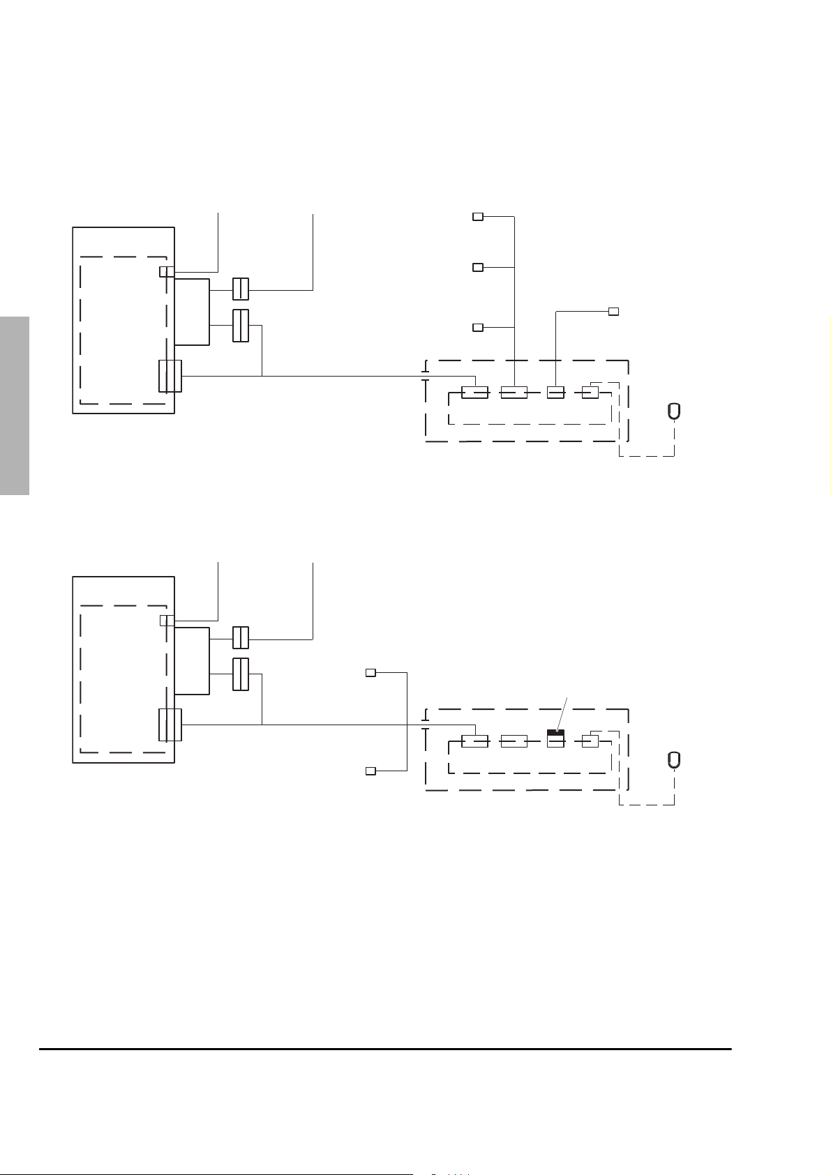
Figure 2.1 shows a diagram of the new vehicle assembly.
Antenna*
1
BER bracket
J1
Antenna
cable*
C3 P1
Power supply*
Power cable*
UDT
option*
Digital
input/output
option*
Audio accessory option*
BER
2
Power
supply filter
J2
C2
C1
C1
System cable
BER - CH (HG5114)
. PTT
. End a call
. Activate horn
X1 X2
*Equipment not supplied by manufacturer
Figure 2.1 VEHICLE ASSEMBLY INSTALLATION DIAGRAM - HT8333
Antenna*
3
BER bracket
J1
Antenna
cable*
C3 P1
Power supply*
Power cable*
Accessory
cable
(HG5115)*
CH
CH cradle
(HG5116)
X3 X4
External LS
option*
LS-
microphone
Ce document est la propriété de EADS Secure Networks et ne doit pas être reproduit ou communiqué sans autorisation
This document is the property of EADS Secure Networks and should not be copied or circulated without permission
BER
4
Power
supply filter
J2
C2
C1
C1
LS option*
C3
System cable
BER - CH (HG4354)
UDT
option*
C4
X1 X2
*Equipment not supplied by manufacturer
Figure 2.2 VEHICLE ASSEMBLY INSTALLATION DIAGRAM - HT8338
5
External
External LS configuration
plug (HT8342)
X3 X4
CH
CH cradle
LS-
microphone
Page TMO - PS11061AENAA01 Vehicle-Mounted TPM700 Technical Manual
2-2 14/10/08 Description

2.2 PHYSICAL DESCRIPTION
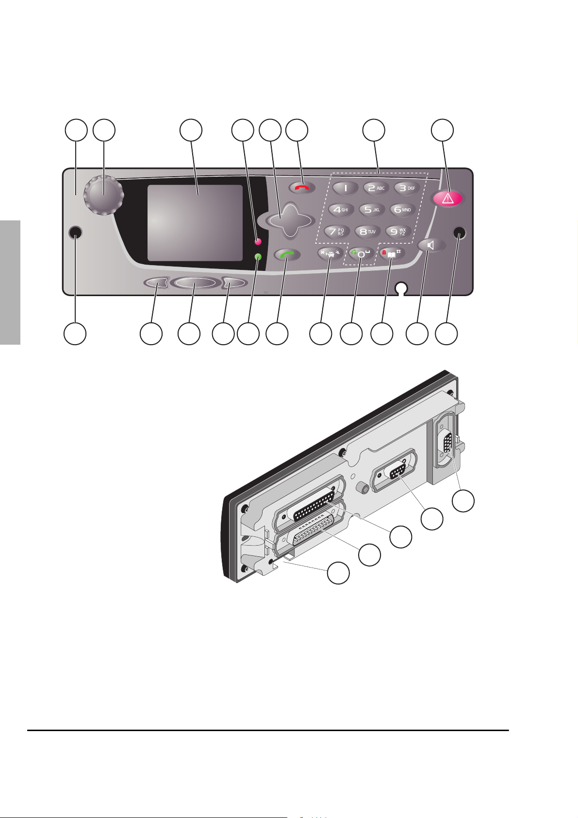
2.2.1 Control Head (Figure 2.3)
The Control Head, which is mounted on the dashboard, provides the man-machine
interface.
The front panel of the Control Head comprises:
• the send (item 14) and end call (item 6) keys
• the directory selection key (item 16)
• a transmit LED (item 4)
• an emergency key (item 8)
1
• a key for switching to VePeaWay mode (depends on project) (item 13)
• a display (item 3)
• the softkeys (items 16 to 18)
The keys and display are described in detail in Document [1] (see section 1.3).
The rear panel of the Control Head has several sockets for connecting cables and
accessories (items 19 to 23).
2
3
4
This document is the property of EADS Secure Networks and should not be copied or circulated without permission
Ce document est la propriété de EADS Secure Networks et ne doit pas être reproduit ou communiqué sans autorisation
Vehicle-Mounted TPM700 Technical Manual TMO - PS11061AENAA01 Page
Description 14/10/08 2-3
5
2134
56 7 8
1
Ce document est la propriété de EADS Secure Networks et ne doit pas être reproduit ou communiqué sans autorisation
This document is the property of EADS Secure Networks and should not be copied or circulated without permission
2
91817161514121110
Key
1 -Control Head
2 -Switch the terminal on and off
volume control
3
4
3-Screen
4 -Red LED (transmit on)
5 -Navigation key
6 -End of call/call rejected
7 -Alphanumeric keypad
8 -Emergency key
9 -Captive screws
10 -Activate/deactivate loudspeaker/horn
11 -Access the selector (long press)
12 -Phone call (long press)
13 -VePeaWay mode (depending on project)
(short press)
14 -Send a call/accept a call
15 -Green LED (terminal registration)
16 -Right soft key
17 -Shortcut button
18 -Left soft key
19 -Sub-D 15-pin female speaker microphone socket
20 -Sub-D 9-pin female LS audio socket
21 -Sub-D 25-pin female accessory socket
22 -Sub-D 25-pin male operating socket
23 -Slot for rubber retaining piece
1Figure 2.3
2Figure 2.3
3Figure 2.3
4Figure 2.3
5Figure 2.3
6Figure 2.3
7Figure 2.3
8Figure 2.3
13
9
19
20
21
22
23
5
Figure 2.3 CONTROL HEAD
Page TMO - PS11061AENAA01 Vehicle-Mounted TPM700 Technical Manual
2-4 14/10/08 Description

2.2.2 Transmitter/receiver unit (BER) (Figure 2.4)
The BER is a box that performs the following functions:
• charge of the Control Head from the vehicle battery
• audio amplification and management of accessories and peripheral devices such as the
speaker microphone, loudspeakers and UDT.
The BER (item 1) consists of the following items:
• a SUB-D 9-pin female socket (item 2) protected by a sealed, captive plug, and used for
downloading the software to the BER
• a SUB-D 25 pin male socket (item 3) providing the operating link with the Control Head
• a TNC female connector (item 4) for the antenna output
Key
1 -BER
2 -Sub-D 9-pin socket
3 -Sub-D 25-pin operating socket
4 -TNC coaxial socket
1
2
1
1Figure 2.4
2Figure 2.4
3Figure 2.4
4Figure 2.4
3
4
This document is the property of EADS Secure Networks and should not be copied or circulated without permission
Ce document est la propriété de EADS Secure Networks et ne doit pas être reproduit ou communiqué sans autorisation
3
Figure 2.4 BER
Vehicle-Mounted TPM700 Technical Manual TMO - PS11061AENAA01 Page
Description 14/10/08 2-5
4
2
5
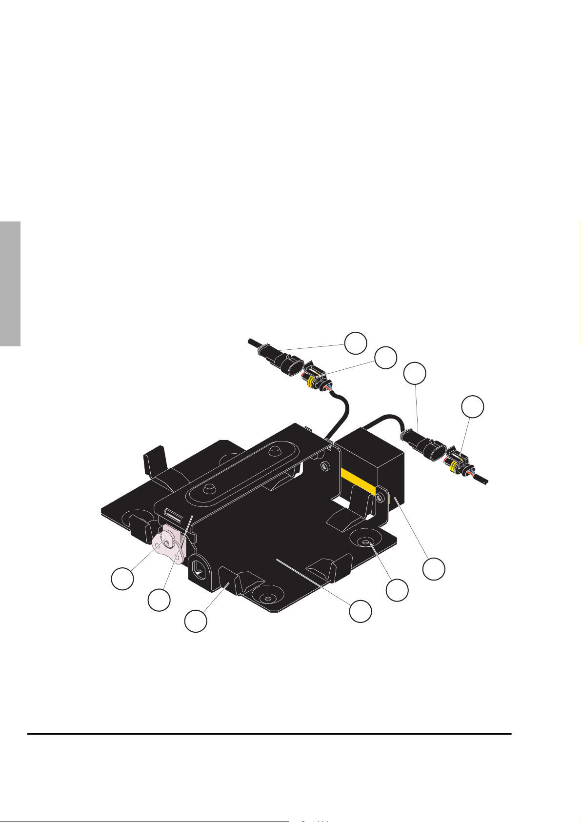
2.2.3 Simplified BER bracket (Figure 2.5)
1Fi
5
K
The simplified BER bracket secures and immobilises the BER in the vehicle boot by means
of six clips (item 8) and a removable flange (item 9) maintained in place by a locking
mechanism (item 10). The simplified BER bracket is also used to interconnect the BER,
1
system cable and power supply cable through a power supply filter.
The simplified BER bracket (item 7) is fitted with a power supply filter (item 5) consisting of:
• a cable fitted with a female 2-pin AMP 2 connector (item 3) for connecting the power
supply cable (item 4)
Ce document est la propriété de EADS Secure Networks et ne doit pas être reproduit ou communiqué sans autorisation
This document is the property of EADS Secure Networks and should not be copied or circulated without permission
• a cable fitted with a male 2-pin AMP 2 connector (item 2) for connecting the system
cable female 2-pin AMP connector (item 1)
The simplified BER bracket is mounted in the vehicle boot by means of four fixing bosses
2
1 -Female 2-pin AMP connector
2 -Male 2-pin AMP connector
3 -Female 2-pin AMP connector
4 -Male 2-pin AMP connector
5 -Power supply filter
6 -Fixing bosses and holes
7 -Simplified BER bracket
8 -Retaining clips
3
9 -Removable flange
10 -Locking mechanism
and holes (item 6) in the bracket.
ey
gure 2.
2Figure 2.5
1
2
3
3Figure 2.5
4Figure 2.5
5Figure 2.5
6Figure 2.5
7Figure 2.5
8Figure 2.5
9Figure 2.5
4
10Figure 2.5
4
10
6
9
7
8
Figure 2.5 SIMPLIFIED BER BRACKET
5
Page TMO - PS11061AENAA01 Vehicle-Mounted TPM700 Technical Manual
5
TR_MC2_SUP-BERLF_SIMP_ECH_01_01
2-6 14/10/08 Description

2.2.4 Cables
2.2.4.1 System cable
The system cable connects the CH to the BER. Access to the 12 V vehicle battery is on the
25-pin system cable connector via a filter assembly mounted on the simplified BER
bracket.
2.2.4.2 Accessory cable
The system cable connects the CH to the BER and to the accessories:
• external loudspeaker
• data terminal
2.3 SPECIFICATIONS
2.3.1 Hardware specifications
Dimensions (h x l x d)
• 58 x 188 x 39 mm
Dimensions of BER (h x l x d)
• 220 X 43 X 168 mm
1
2
3
Dimensions of simplified BER bracket (h x l x d)
• 220 x 65 x 240 mm
Weight of BER
• about 1.7 kg
2.3.2 Electrical specifications
Power supply
This document is the property of EADS Secure Networks and should not be copied or circulated without permission
Ce document est la propriété de EADS Secure Networks et ne doit pas être reproduit ou communiqué sans autorisation
• external DC 12 V battery power supply (see tolerances in section 2.3.4.1)
Maximum consumption
• transmitting (max. power): 5A
• receiving: 0.5 A
Power supply filter protection
• fuse: 7.5 A fitted in the BER bracket
4
5
Vehicle-Mounted TPM700 Technical Manual TMO - PS11061AENAA01 Page
Description 14/10/08 2-7

2.3.3 Technical specifications
• Transmit mode: half-duplex in BS-connected mode, simplex in direct mode
• Duplex spacing (transmit frequency – receive frequency): variable between ± 5 MHz
1
and ± 20 MHz for WB BERs
• Step (channel spacing): 10 kHz or 12.5 kHz
• Reception sensitivity: - 119 dBm for WB BERs
2.3.4 External interface specifications
2.3.4.1 Power supply input
• Source: 10.8 V to 15.6 V at the power supply cable end, battery side
2
2.3.4.2 Antenna output
• Socket: female TNC
• Impedance: 50 Ohms
2.3.5 Environmental specifications
2.3.5.1 Ambiant temperature for use
3
The ranges for use are:
• Normal temperature range: + 10 ° to + 35 °C
• EXtreme temperature range: - 20 ° to + 55 °C
Ce document est la propriété de EADS Secure Networks et ne doit pas être reproduit ou communiqué sans autorisation
This document is the property of EADS Secure Networks and should not be copied or circulated without permission
The maximum temperature increase is 20 °C per hour.
2.3.5.2 Humid heat
4
The equipment is conform with the extreme humid heat test: 95 % humidity, duration: 10
days, temperature + 45.5 °C (in accordance with standard CEI 68.2.3).
5
Page TMO - PS11061AENAA01 Vehicle-Mounted TPM700 Technical Manual
2-8 14/10/08 Description

2.4 FUNCTIONAL DESCRIPTION
The vehicle assembly includes the transmit/receive and logic functions used to access the
different PMR system services. These functions are provided by the wide band BER box.
For the vehicle assembly to be operational, the wide band BER must be loaded, configured
and customised by the TPS (see section 1.3, Document [3]):
• Loading involves saving the operating software for the project in the wide band BER’s
memory. This software provides access to all the functionalities offered by the PMR
system.
• Configuration involves entering the wide band BER’s parameters, in particular the wide
band BER’s RFSI address,
• Customisation involves adapting the wide band BER to the user profile by authorising or
locking access to the different services of the PMR system.
The Control Head provides the user interface.
1
2
3
This document is the property of EADS Secure Networks and should not be copied or circulated without permission
Ce document est la propriété de EADS Secure Networks et ne doit pas être reproduit ou communiqué sans autorisation
Vehicle-Mounted TPM700 Technical Manual TMO - PS11061AENAA01 Page
Description 14/10/08 2-9
4
5
 Loading...