

Cassese CS969 User & Parts Manual
1
USER & PARTS MANUAL
Version 3
10/2018
Read carefully before using the machine
© Cassese 2018
DOUBE MITRE SAW 45°
SCIE PNEUMATIQUE DOUBLE LAME 45°
RAPPORT VERITAS N°6058665-1-1-CS969

USER MANUAL
CS969
2

USER MANUAL
CS969
3
INDEX
1 / USER MANUAL / ENGLISH ......................................................................................... 6
SAFETY FEATURES .............................................................................................................................................. 6
1.A.a Position of the labels on the machine: ...........................................................................................................................6
USER RULES ....................................................................................................................................................... 9
WHAT SHOULDN’T BE DONE .............................................................................................................................. 9
SAFE USE OF THE MACHINE. ............................................................................................................................. 10
2 / DESCRIPTION .......................................................................................................... 11
DESCRIPTION OF THE CS969 MAIN PARTS ........................................................................................................ 11
3 / TECHNICAL DATAS ................................................................................................... 13
CUTTING CAPACITY .......................................................................................................................................... 14
OPTIONS : ........................................................................................................................................................ 14
4 / INTRODUCTION ....................................................................................................... 15
RESIDUAL RISKS ............................................................................................................................................... 15
WARRANTY ...................................................................................................................................................... 15
5 / HANDLING AND UNPACKING .................................................................................. 16
REMOVING OF TRANSPORTATION SAFETY ....................................................................................................... 19
6 / SETTING UP THE MACHINE ...................................................................................... 20
LEFT AND RIGHT ARM MOUNTING ................................................................................................................... 22
ELECTRICAL CONNECTION ................................................................................................................................ 25
AIR LINE FITTINGS ............................................................................................................................................ 25
ASPIRATION ..................................................................................................................................................... 26
7 / STARTING UP .......................................................................................................... 28
CONTROL PANEL .............................................................................................................................................. 28
MAIN SWITCH .................................................................................................................................................. 28
SAWING ........................................................................................................................................................... 29
7.C.a Setting the vertical and horizontal clamps ...................................................................................................................29
CUTTING FEED RATE ......................................................................................................................................... 30
FIRST CUT ON THE LEFT .................................................................................................................................... 30
MEASURING THE FIRST PIECE (MOBILE STOP) ................................................................................................... 31
7.F.a Measuring the rebate (internal) ...................................................................................................................................31
7.F.b External measurement .................................................................................................................................................32
RETRACTABLE STOP ......................................................................................................................................... 32
7.G.a Storing a second cutting point in the memory .............................................................................................................32
7.G.b Second cut ....................................................................................................................................................................33
7.G.c Cut on the end of a moulding (right cut) ......................................................................................................................33
8 / MAINTENANCE & SERVICING .................................................................................. 35
PROCEDURE TO ACCES INSIDE THE MACHINE ................................................................................................... 35
8.A.a Opening the main case .................................................................................................................................................35

USER MANUAL
CS969
4
8.A.b Removing the blades ....................................................................................................................................................35
8.A.c Refiting the blades .......................................................................................................................................................36
8.A.d Closing the main case ...................................................................................................................................................37
8.A.e Replacing the martyr cube ...........................................................................................................................................37
8.A.f Opening the electrical cabinet block ............................................................................................................................38
9 / MAINTENANCE ........................................................................................................ 39
TYPE OF BLADE RECOMMENDED FOR MULTI-PURPOSE CUTTING ..................................................................... 39
PANNES ........................................................................................................................................................... 39
LIST OF WEARING PARTS CS969 ........................................................................................................................ 40
1 / MANUEL D’UTILISATION / FRANCAIS ...................................................................... 41
CONSIGNES DE SECURITE ................................................................................................................................. 41
1.A.a Position des étiquettes sur la machine : .......................................................................................................................41
CONDITIONS D’UTILISATION ............................................................................................................................ 44
CE QU’IL NE FAUT PAS FAIRE ............................................................................................................................ 44
PRATIQUES DE TRAVAIL EN TOUTE SECURITE ................................................................................................... 45
2 /PRESENTATION ........................................................................................................ 47
DESCRIPTION DES PRINCIPAUX ELEMENTS DE LA CS969. .................................................................................. 47
3 / CARACTERISTIQUES TECHNIQUES ............................................................................ 49
CAPACITE DE COUPE ........................................................................................................................................ 50
OPTIONS : ........................................................................................................................................................ 50
4 / INTRODUCTION ....................................................................................................... 51
RISQUES RESIDUELS ......................................................................................................................................... 51
GARANTIE ........................................................................................................................................................ 51
5 / DEBALLAGE ET MANUTENTION ............................................................................... 52
DEMONTAGE DE L’EQUERRE DE SECURITE TRANSPORT .................................................................................... 55
6 / MISE EN PLACE DE LA MACHINE .............................................................................. 56
MONTAGE DES BRAS GAUCHE ET DROIT .......................................................................................................... 58
BRANCHEMENT ELECTRIQUE ........................................................................................................................... 61
BRANCHEMENT PNEUMATIQUE ...................................................................................................................... 61
ASPIRATION. .................................................................................................................................................... 62
7 / MISE EN SERVICE ..................................................................................................... 64
TABLEAU DE COMMANDES. ............................................................................................................................. 64
SECTIONNEUR GENERAL .................................................................................................................................. 64
SCIAGE ............................................................................................................................................................. 65
7.C.a Réglage des presseurs verticaux et horizontaux ..........................................................................................................65
AVANCE DE COUPE........................................................................................................................................... 66
PREMIERE COUPE A GAUCHE ........................................................................................................................... 67
MESURE DU PREMIER MORCEAU (BUTEE MOBILE) ........................................................................................... 68
7.F.a Mesure fond de feuillure (Mesure intérieure) ..............................................................................................................68
7.F.b Mesure en cote extérieure ...........................................................................................................................................68
BUTEE ESCAMOTABLE ...................................................................................................................................... 69

USER MANUAL
CS969
5
7.G.a Mémorisation d’un deuxième point de coupe ..............................................................................................................69
7.G.b Deuxième coupe ...........................................................................................................................................................70
7.G.c Coupe sur fin de moulure (coupe à droite) ...................................................................................................................70
8 / MAINTENANCE ........................................................................................................ 72
PROCEDURE POUR ACCÉDER A L’INTÉRIEUR DE LA MACHINE ........................................................................... 72
8.A.a Ouverture du capot principal .......................................................................................................................................72
8.A.b Démonter les lames ......................................................................................................................................................73
8.A.c Remontage des lames ..................................................................................................................................................74
8.A.d Fermeture du capot principal .......................................................................................................................................74
8.A.e Remplacement du support de chute ............................................................................................................................74
8.A.f Ouverture de l’armoire électrique ................................................................................................................................75
9 / ENTRETIEN .............................................................................................................. 76
TYPE DE LAME CONSEILLEE POUR COUPES MULTI-USAGES ............................................................................... 76
PANNES ........................................................................................................................................................... 76
LISTE DES PIECES D’USURE CS 969 .................................................................................................................... 78
10 ANNEXE ..................................................................................................................... 79
BILL OF MATERIAL - NOMENCLATURE CS969. ................................................................................................... 79

6
1 / USER MANUAL / ENGLISH
SAFETY FEATURES
Your safety is our priority
1.A.a Position of the labels on the machine:
10
4
5 6 7
3 8 2
9
10
11
1
USER MANUAL
CS969
7
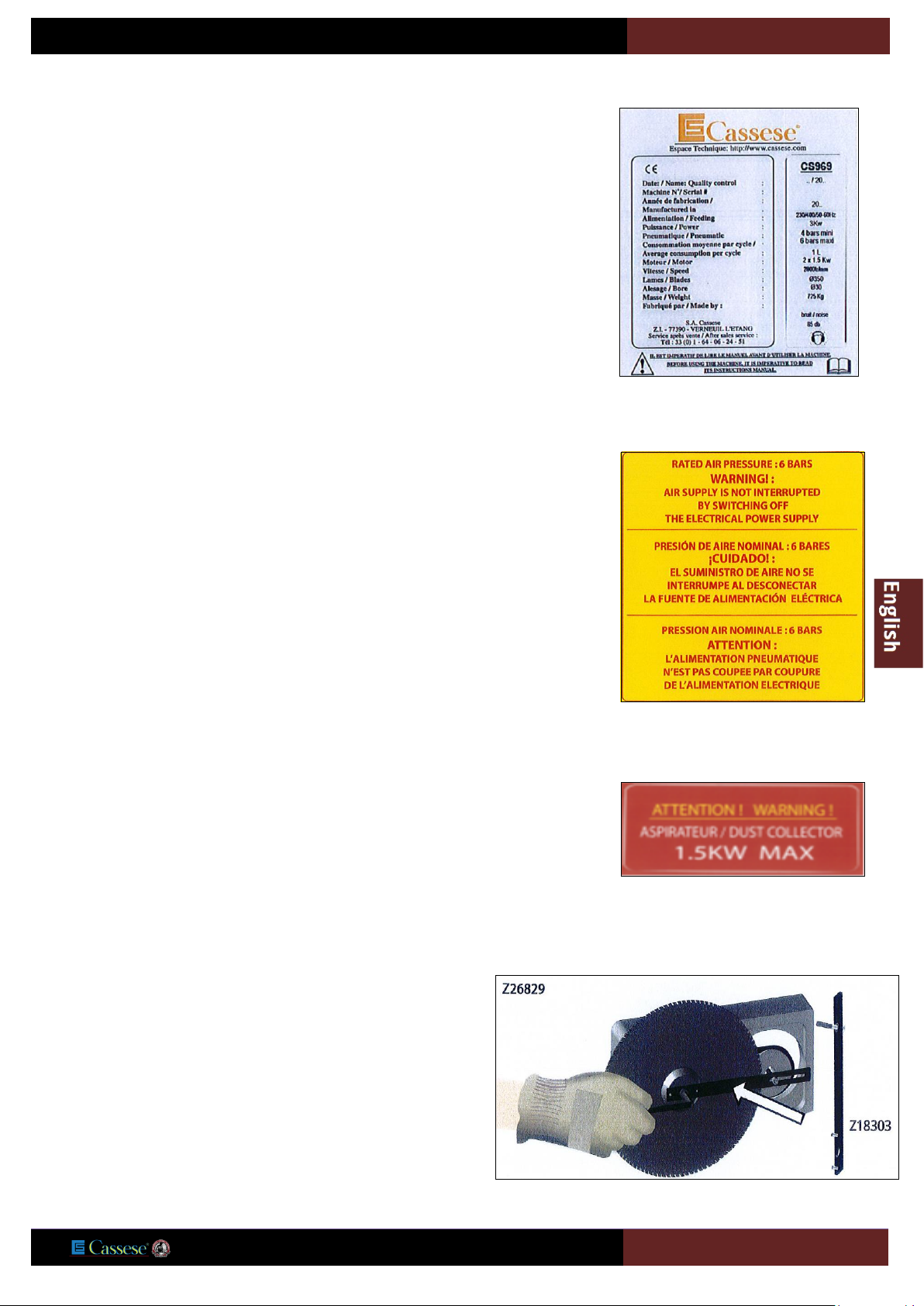
1/ CS969 identitying plate showing the technical datas of your
machine
3/ Information about maximum power of dust collector
2/ Information about pressure supply
4/ This label inform you about place of mandatory tools for
dismounting and mouting of saw blades.
USER MANUAL
CS969
8
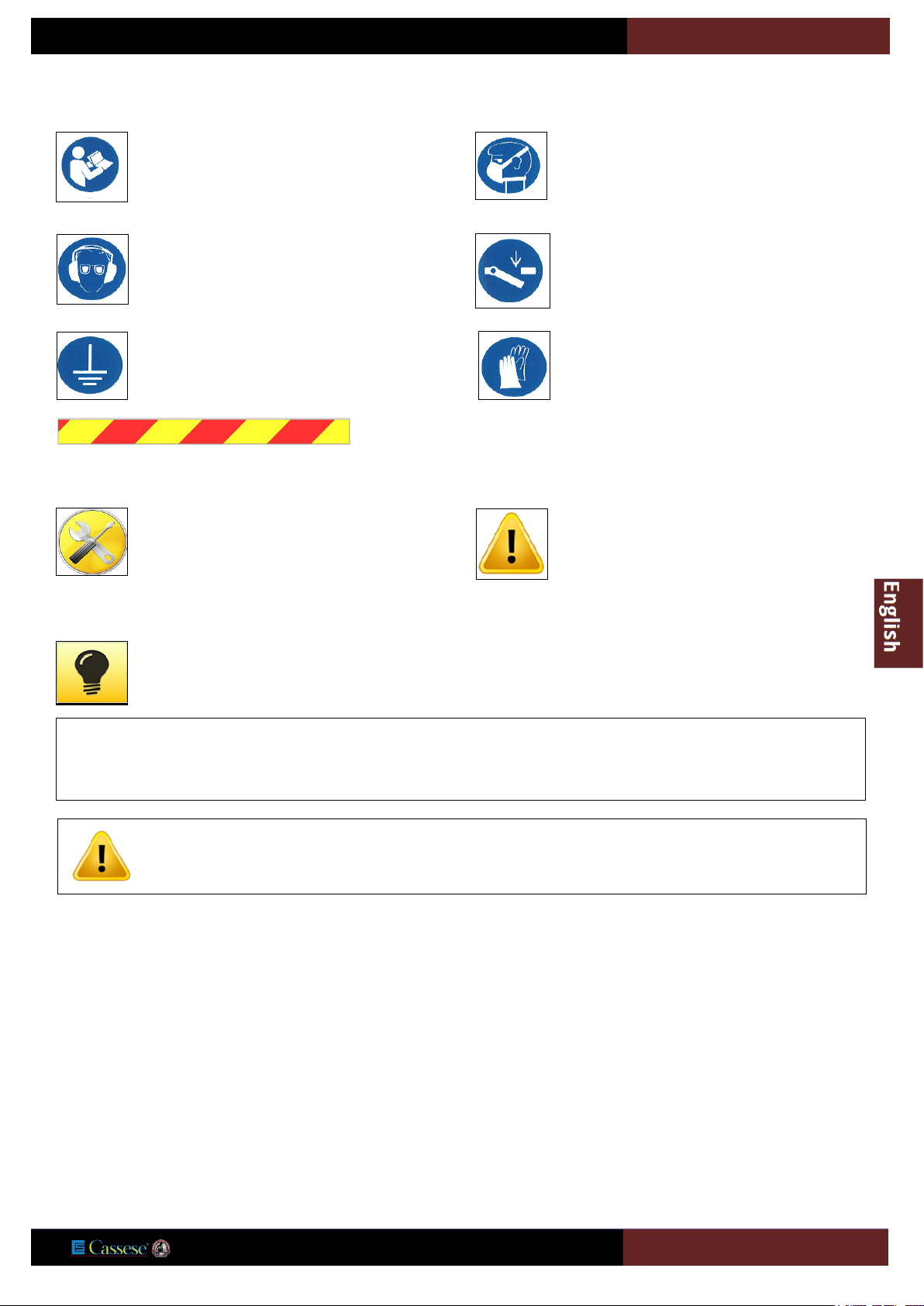
This icon in the manual mentions some tricks
that can help you saving time or improve your
production.
This symbol in the manual is to mention safety
instructions.
This icon in the manual will identify a list of
required tools to perform a procedure.
9/ This icon informs you about mandatory
grounding of machine electrical connection and
vacuum system.
5/ This symbol on the machine reminds the
operator to read this manual before operating
this machine.
BEFORE PERFORMING ANY MAINTENANCE ON THE MACHINE, UNPLUG AND LOCK THE ELECTRIC AND PNEUMATIC
SUPPLIES. DO NOT USE THE MACHINE IF ONE COVER IS MISSING.
7/ This symbol on the machine reminds the
operator to wear acoustic protections and
protection glasses before operating this
machine.
10/ This symbol on the machine asks you to
wear gloves before you touch the blades.
8/ This icon on the machine advises you to switch
off electric power before performing maintenance
on the machine.
6/ This symbol shows that it is advised to wear a
dust protecton mask
11/ These marks are showing the limit that you shouldn’t cross with your hands.
.
READ CAREFULLY THE SAFETY INSTRUCTIONS OF THAT BOOK BEFORE
OPERATING THE MACHINE.
USER MANUAL
CS969
9
USER RULES
Saw CS 969 is a machine used to cut 45° mitres on all mouldings with solid or reconstituted wood base, and with or without coating
(paint, varnish, plastic coating, paper, etc.).
Are excluded :
• Mouldings that don’t have a 90° angle back on at least 5mm,
• Metal profiles,
• Small plastic profiles (filets, etc...).
Its two circular blades are driven by two electric motors.
The moulding is held automatically by vertical and horizontal pneumatic cylinders.
A two-hand control, actuating both clamping and cutting, ensures operator safety by keeping hands out of range of the blades.
The electrical control equipment is placed in a cabinet in front of the machine and on the right side.
The pneumatic equipment is secured in the base of the machine behind the electrical cabinet.
This machine was built to meet safety and hygiene requirements. It is therefore forbidden to modify the electrical and pneumatic
equipment, remove protective equipment installed on delivery or modify the machine safety devices.
Saw CS 969 cannot be used by more than one operator at a time.
To prevent electric shocks and overload, some protections should be installed by the user on the electric supplying line to the machine,
according to EN60204-1 :2006, Article 7
WHAT SHOULDN’T BE DONE
- At no time the operator should engage his hands in the clamp area, nor in the cutting area behind the brushes. (blades are rotating
even when returned to the back position)
- Do not use steel blades (HS type)
- Prior to any maintenance operation, switch off electric and pneumatic supply by using and locking their switches. (14 & 16, Page 11).
- Switch off the machine by using the electric contactor on the right side of the machine and lock it with a padlock.
- Only one person at a time should use the machine. This person is responsible for the controls.
- All adjustments should be performed with the cover closed. At no moment the operator should put his hands inside the covers. This
measure is intended to guarantee the safety of the operator, who should under no circumstances insert his hands inside the cover.
- If none of the clamps can hold the mouldings, the cut of that moulding is forbidden.
- Do never use the machine with a missing panel.
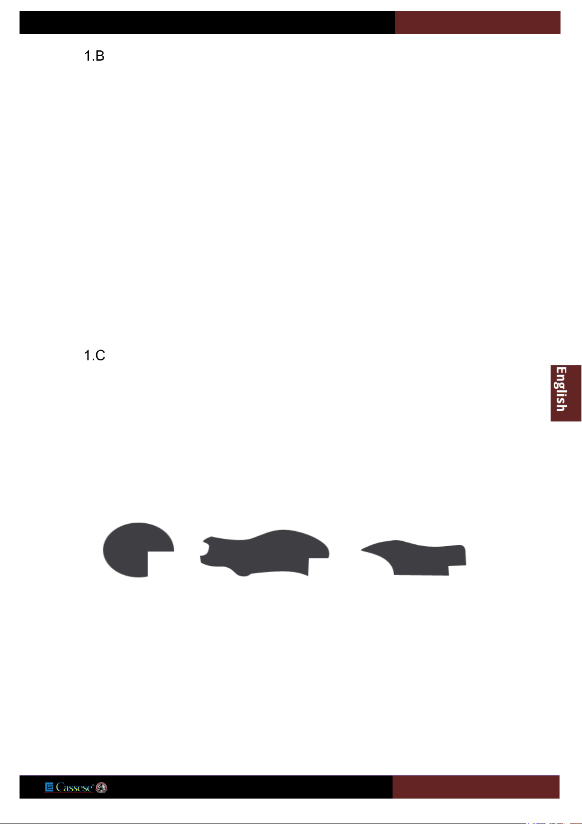
- These particular mouldings cannot be cut on the CS969.

USER MANUAL
CS969
10
SAFE USE OF THE MACHINE.
It is essential that the operators are:
a) Trained about the use, the adjustment and the way of working of the machine.
b) Informed about the things that affect the noise exposition such as:
1) Blades that are designed to limit noise emission,
2) Selection of the optimal speed,
3) Maintenance of the blades and the machine.
c) Informed about the things that affect dust exposition such as:
1) Used type of material,
2) Importance of the dust extractor,
3) Correct setting of the covers/deflectors,
4) Dust collector should be turned on before you start cutting.
d) Informed about the necessity to wear sufficient individual protection such as:
1) Ear protections.
2) Mask protection against dust to avoid breathing dangerous material.
3) Protecting gloves when touching blades (it is also recommended to use a blade carrying tool to transport the blades).
e) It is important:
1) That the machine is installed on a flat and a cleaned floor,
2) To have a sufficient light in the working area,
3) To stocks and finished parts are kept close to the operator’s normal working position,
4) To stop the machine and lock the power sources before you perform any maintenance or when the machine
is left without supervision,
5) To report any failure of the machine such as missing cover or damaged parts, as soon as they are discovered,
6) To adopt safety procedures for cleaning and maintenance and remove chips and dust regularly to prevent any
risk of fire,
7) To not remove any waste or piece of moulding while the machine is in function,
8) To not use the machine if some protection covers are not installed and all in perfect condition,
9) To not do OFF/ON/OFF… in short time, this could damage the machine.
f) It is a necessity for the operator to:
1) Follow operating, maintenance and repair instructions of the cutting blades‘manufacture,
2) Respect the maximum cutting indicated speed of the blades,
3) Use blades that are correctly sharpened.
USER MANUAL
CS969
11
2 / DESCRIPTION
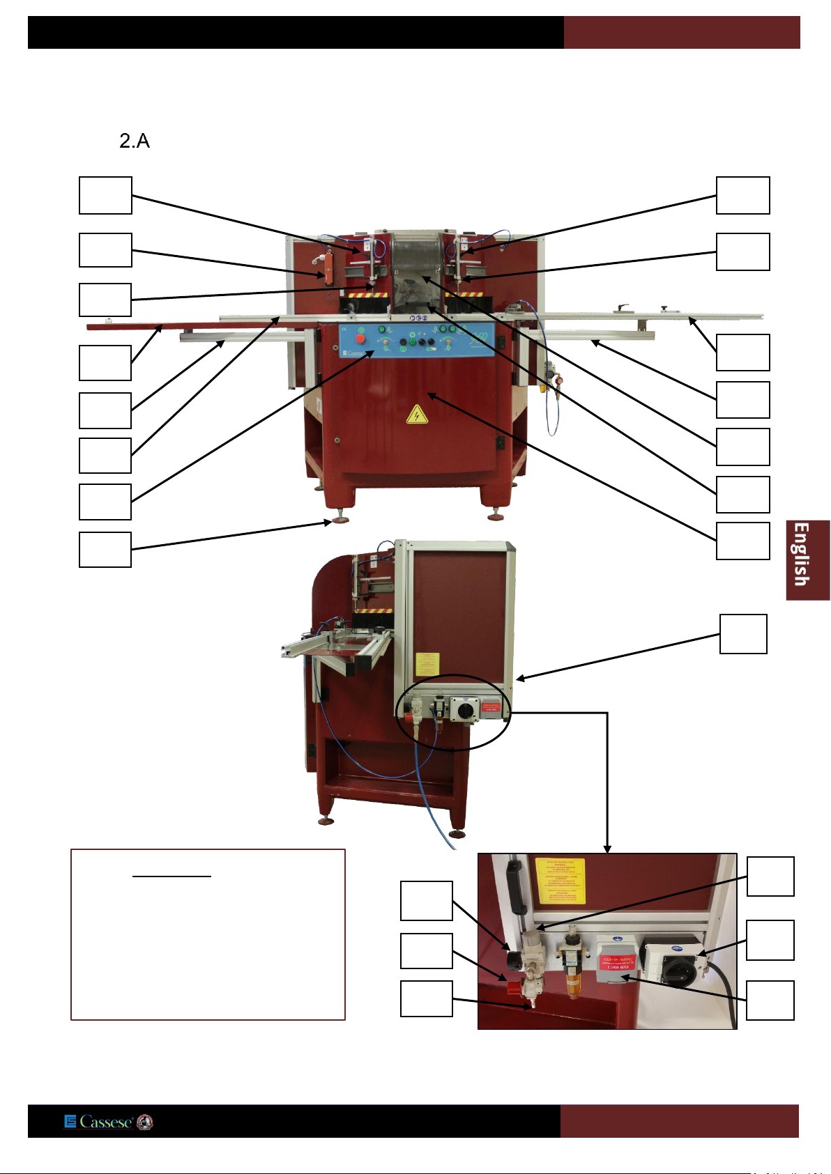
DESCRIPTION OF THE CS969 MAIN PARTS
2
12
4
OPTIONS:
Right extension arm:
Z28432 = 2 Meters/Z28431=1 Meter.
Digital measuring stop “Smart Stop”(on
request / Can not be retrofitted
afterwards):
7
9 6 15
20
3
5
8
10
1
19
11
21
14
22
13
16
17
18
USER MANUAL
CS969
12
Description
Label
Main Cover
1
Left vertical clamp handle
2
Right vertical clamp handle
3
Left vertical clamp
4
Right vertical clamp
5
Moulding guide
6
Left arm
7
Right arm
8
Left table bracket
9
Right table bracket
10
Electrical cabinet door
11
Safety lock
12
Air pressure-regulating valve
13
Air switch (can be locked with a locker)
14
Control panel
15
Main circuit Isolating switch
16
Electrical plug (220V) for dust collector,.1.5 Kw MAX
17
Dust pipe connectors Ø 120 mm
18
Main Cover handle
19
Levelling feet + locking nuts (x4).
20
Air pressure gauge
21
Pneumatic quick coupling
22

USER MANUAL
CS969
13
3 / TECHNICAL DATAS
DESCRIPTION :
CS969
Year of manufacturing:
see label 1 on the machine
Cutting capacity:
Maximum width:
Maximum height of moulding:
160 mm
110 mm
Dimension of the blades:
Ø 350 mm
Bore:
Ø 30 mm
RPM:
3500 tr/mn for 60Hz and 2800 tr/mn for 50Hz
Maximum length to be cut:
1500 mm
Electrical supply:
230v MONO-30 A /
230v TRI-16 A /
400 TRI-10 A
Power cord:
3 x 2.5 HO7RNF 3G2.5 (230v MONO) /
4 x 1.5 HO7RNF 4G1,5 (230v and 400 v TRI).
2 Motors, power: (conformity EN 30204)
(2x) 1,5 Kw
Dust pipe connectors:
(2x) Ø 120mm
Dust collector type in accordance with standards:
To ensure correct extraction of the dust, suction flow should be:
2500m3/h
Thermal Protection/Electrical socket:
8A for 220V TRI / 5 A for 380V TRI
Pneumatic supply:
4 bars mini / 6 bars maxi
Maximum air consumption for 700 cuts per hour:
2.5 Nl per cycle at 6 bar
Weight:
720 Kg
Noise: (ear protections must be wear) Noise information: Measured
according ISO 7960-1995 standard).
see below
Operating condition of noise measurement:
1 Metering at operator position, not cutting, dust collector off: 81dB (A )
9 Metering at one meter not cutting, dust collector on / reference surface: 85dB (A )
9 Metering at one meter, machine in cutting process, dust collector on / reference surface: 89dB (A )
These values are measured values; they are not necessarily showing safe working conditions.
Even if there is a correspondence between emission and exposure level, these measures can’t be used to determine the necessary
protections to wear.
Parameters such as workshop configuration, other noise sources and machinery or other manufacturing process can affect the
exposure noise level of the operator.
Also allowed exposure level can fluctuate from a country to another one.
However, these values will help the user to evaluate the risk of using this machine.
Measurement report: BUREAU VERITAS N° 6164860-1/1-Z49SOP.
USER MANUAL
CS969
14
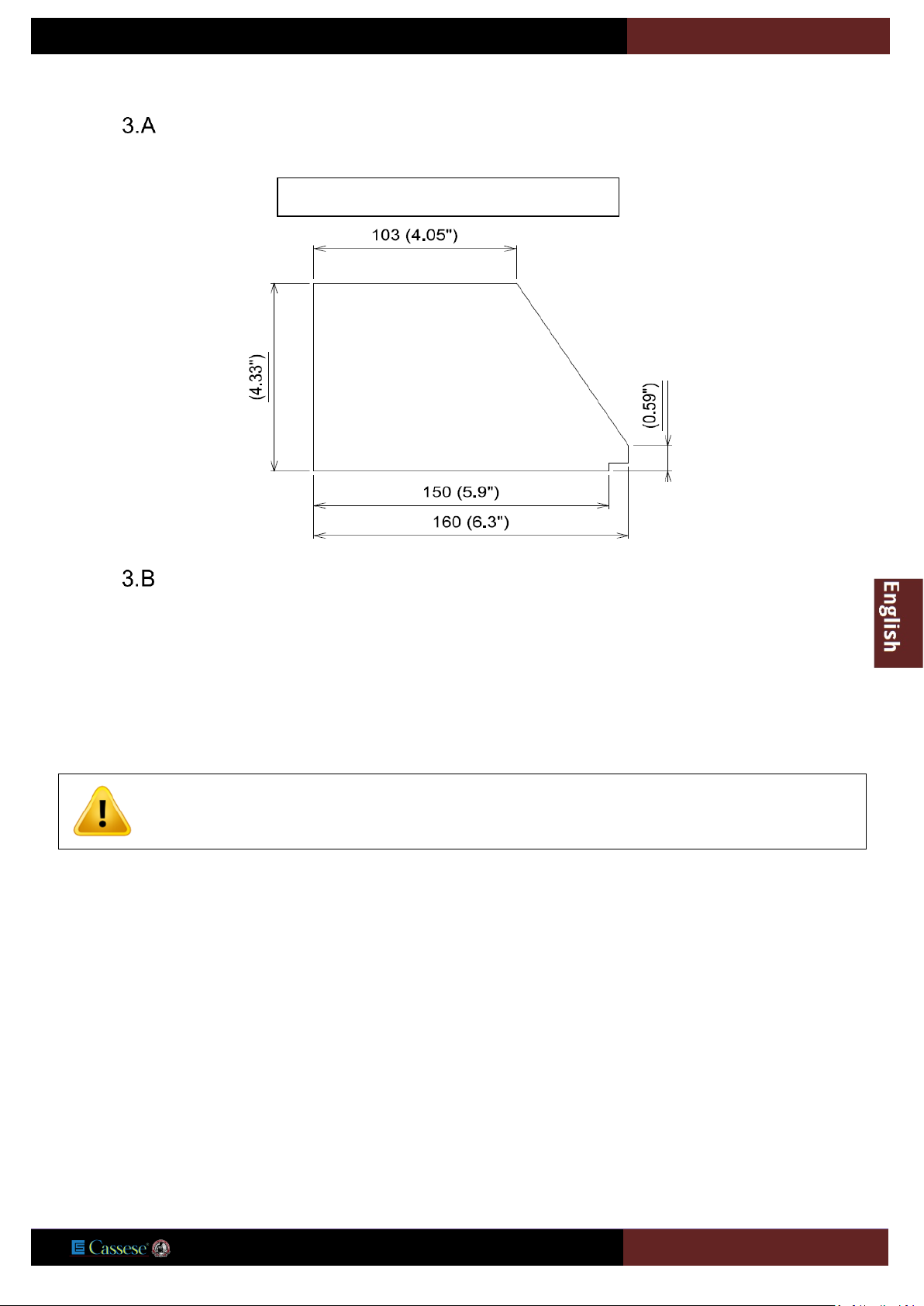
CUTTING CAPACITY
OPTIONS :
- S/A RIGHT EXTENSION ARM 1M Z28431.
- S/A RIGHT EXTENSION ARM 2M Z28432.
- S/A NUMERIC STOP “SMART STOP” Z28600.
- S/A RIGHT EXTENSION ARM 1M for SMART STOP Z18220.
NUMERIC SMART STOP Sub-assembly requires a factory mounting.
Cutting Capacity (Overall)

USER MANUAL
CS969
15
4 / INTRODUCTION
Saw CS 969 is a machine used to cut 45° mitres on all mouldings with solid or reconstituted wood base, and with or without coating
(paint, varnish, plastic coating, paper, metal leaf such as gold, bronze, aluminium, etc.).
It cannot be used for:
- Moulding profiles that do not have a 90° heel greater than 5 mm in height,
- Any metal profiles,
- Thin extruded plastic profiles: (plastic cords, trimmings, etc.)
Its two circular blades are driven by two electric motors.
The moulding is held automatically by vertical and horizontal pneumatic cylinders.
A two-hand control, actuating both clamping and cutting, ensures operator safety by keeping hands out of range of the blades.
The electrical control equipment is placed in a cabinet in front of the machine.
The pneumatic equipment is secured in the base of the machine behind the electrical cabinet.
This machine was built to meet safety and hygiene requirements. It is therefore forbidden to modify the electrical and pneumatic
equipment, remove protective equipment installed on delivery or modify the machine safety devices.
Saw CS 969 cannot be used by more than one operator at a time.
RESIDUAL RISKS
Hands must never be inserted inside the beyond the plastic screens of the top protection cover as this section contains the pressure
cylinders and rotating saw blades in their high idle position.
WARRANTY
This machine is covered by a one-year warranty, parts and labor included. Wearing parts and damaged parts due to bad use of the
machine are not covered by the warranty.
USER MANUAL
CS969
16
5 / HANDLING AND UNPACKING
This machine is packaged in a crate containing:
-1 Right extension arm with rebate measuring system
-1 Fixed stop
-1 Retractable stop
-1 Left extension arm
-1 Accessories box containing:
-1 S/A blades dismounting tool(Z18303)
-1 10-mm Allen key (to remove blades)
-1 6-mm Allen key (to assembly tables)
-1 5-mm Allen key
-1 4-mm Allen key
-1 2.5-mm Allen key
-1 Allen key for sensor
-1 Quick-fit coupling ¼ (fitted on the machine) / 1 quick-fit coupling
-1 Fuse: 1.25 Amp aM - (2 Amp aM ) glass fuse:1,25 A 5 x20.
-1 Male US connector M ¼ TEFLONE-Z701
-1 Groove connector M ¼ Cyl. -Z556
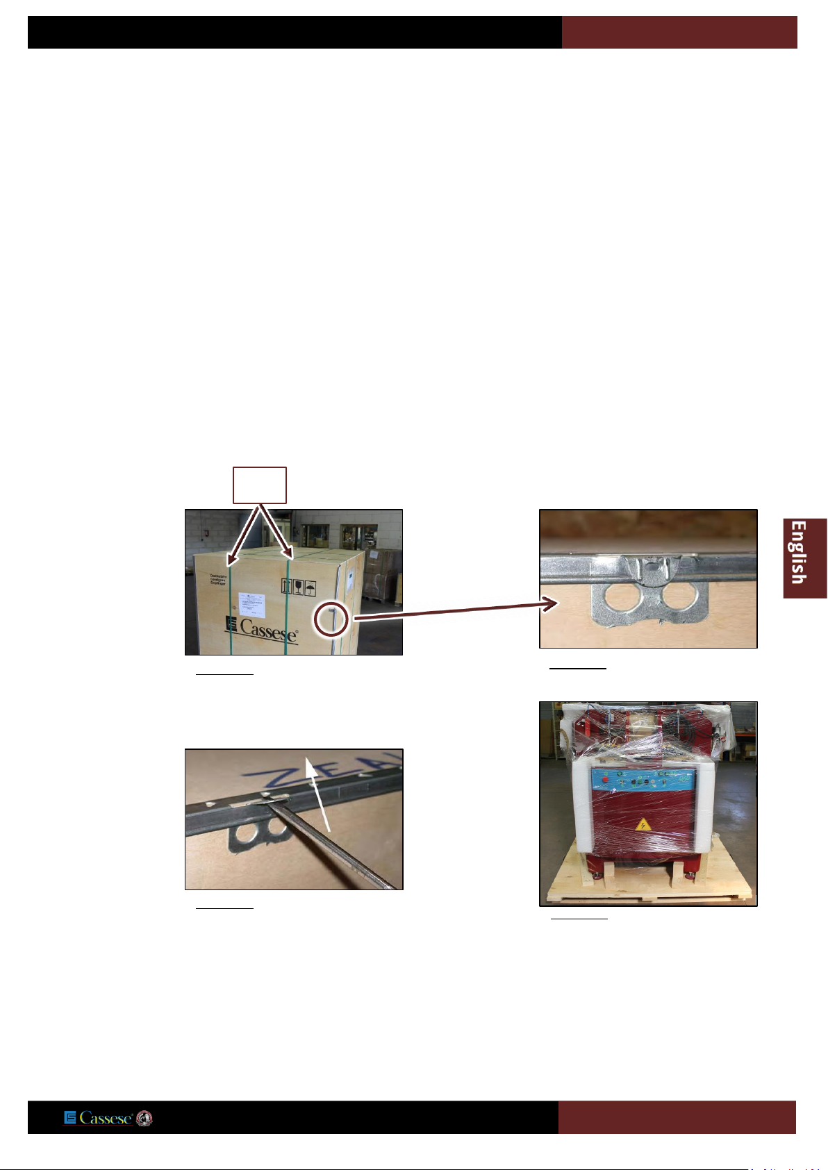
Using scissors, cut
the straps rep: C
which belt the crate
C
Figure 5-1
Figure 5-2
Using a screwdriver
open the fasteners
on the crate
Figure 5-3
then remove the
cover and its 4
sides.
Figure 5-4

USER MANUAL
CS969
17
For handling, a lift truck with forks at least 115 cm long must be used.
The forks must be positioned correctly below the frame: see next figure.
Gross weight of the machine: 725 kg
Remove the table
extension arms
(behind the
machine)
Figure 5-5
Remove the
accessories box
(below the
machine)
Figure 5-6
Remove the
wooden hold from
the feet of the
machine.
Figure 5-7
Screwdriver
Scissors
CAUTION: Setting the forks spacing for moving pallet to the floor:
Front panel = 675 mm - side: 530 mm.
Then set the forks spacing for the remaining movement (see drawing below).
Position of the forks: equidistant from the frame axis. (see drawing below)

USER MANUAL
CS969
18
Once the machine is installed, remove the protection.
Handling from the front
Safety distance = 50 mm
Wooden block 120 x 150 x 850 mm
Fork of the lifting equipment
Handling from the side
Wooden block120 x 150 x 1200 mm
Fork of the lifting equipment
Safety distance = 50 mm
Figure 5-8
USER MANUAL
CS969
19
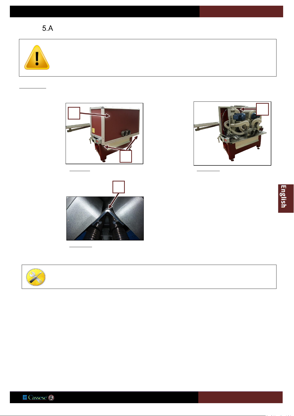
REMOVING OF TRANSPORTATION SAFETY
IMPERATIVE: before setting up your machine,
WARNING
DO NOT PLUG AIR !
Untight captives
screws (A
) and
open the back
cover (C)
Figure 5-9
C
A
Figure 5-10
E
Remove the locking
square (E
) of the
blades' carriage
(6mm Allen key
required)
Figure 5-11
E
5-mm Allen key
6-mm Allen key
USER MANUAL
CS969
20
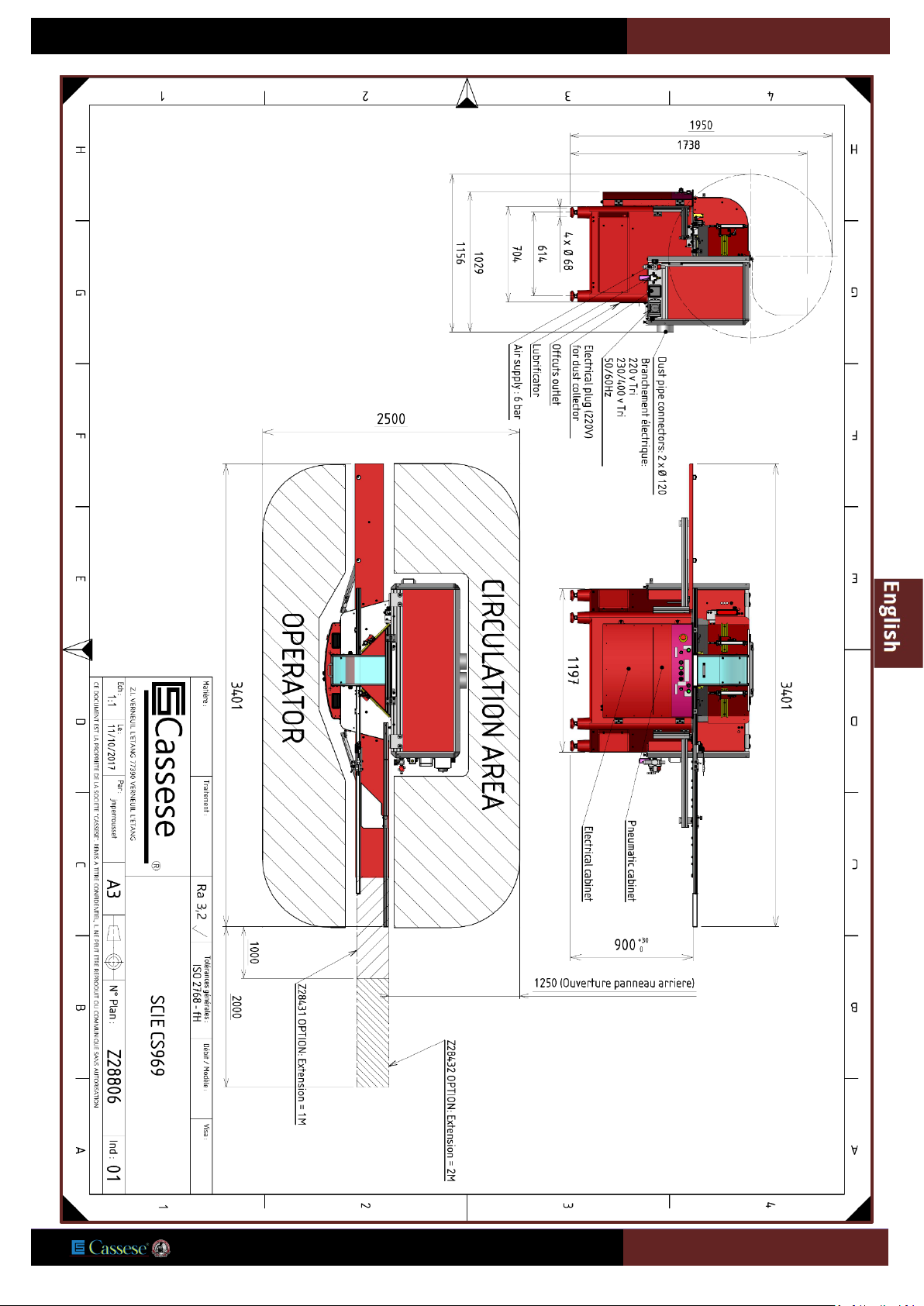
6 / SETTING UP THE MACHINE
There must be sufficient clearance around the machine to allow free
movement and access for maintenance.
The CS969 saw must be placed on a stable and generally flat floor.
Floor must be able to support load of 1250 Kg/m² and 315 Kg for
each foot.
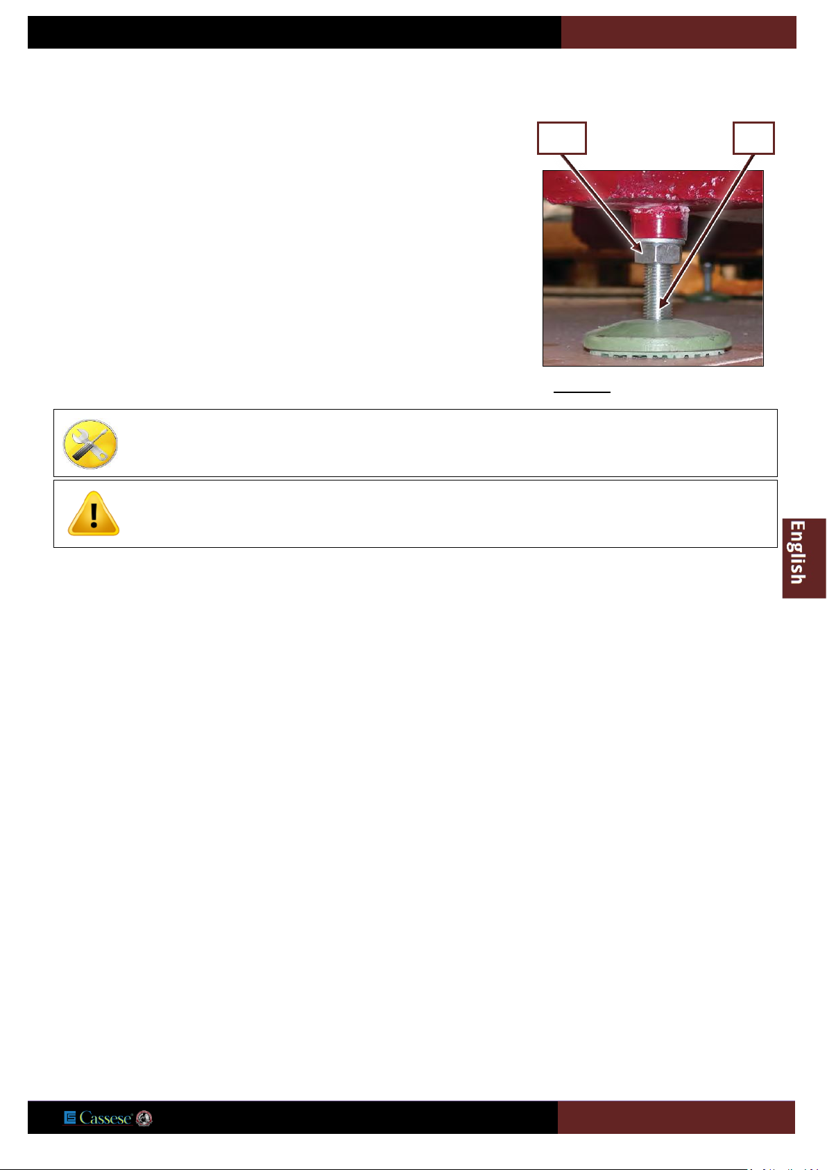
Before making any electrical or pneumatic connections, level the
machine by means of the adjustable feet.
Use a 24-mm open-end spanner for locking nut (CE) and a 12-mm open-end spanner
for base (B).
Tighten locking nut (CE) firmly after adjustment and levelling.
As the work surface is 900 mm from the floor, it may be necessary to install a platform
for operators of short stature.
Sufficient space must be reserved around the machine to ensure a freedom of
movement and good acces for maintenance (see next page)
Open-end spanner 12
Open-end spanner 24
When installing the machine, make sure the floor is leveled and can support the weight of the machine.
The machine must be installed in a dry and temperate place. Choose a location where light will be sufficient to
ensure a comfortable use of equipment.
CE
B
Figure 6-1
USER MANUAL
CS969
21
USER MANUAL
CS969
22
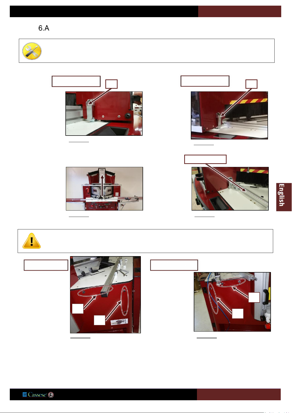
LEFT AND RIGHT ARM MOUNTING
5-mm Allen key
4-mm Allen key
Open-end spanner 10
Release the left
spring clips, SG.
Figure 6-2
SG
Left table side
Release the right
spring clips, SD
Figure 6-3
Right table side
SD
Open the main case
to its highest
position.
Figure 6-4
Figure 6-5
Moulding guide
Do not untighten screws of the moulding guide (factory setting)
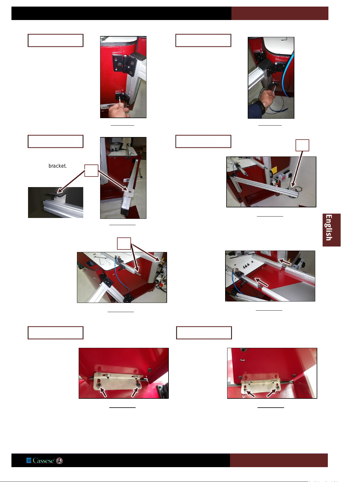
Remove screws A
and B
on the left
side of the machine
frame with a 5-mm
Allen key.
Figure 6-6
Left table side
A
B
Remove screws C
and D
on the right
side of the machine
frame with a 5-mm
Allen key.
Figure 6-7
Right table side
C
D
USER MANUAL
CS969
23
Put in place the left
extension support
bracket, tightening
it with previously
removed screws
(B).
Figure 6-8
Left table side
Put in place the left
extension support
bracket, tightening
it with previously
removed screws
(C).
Figure 6-9
Right table side
Put off the screw (E)
from the bracket.
Figure 6-10
Left table side
E
Put off the screw (F)
from the bracket.
Figure 6-11
Right table side
F
For each side of the
machine, make
sure the splints (G
)
are in place.
Figure 6-12
G
For each side slide
the arm in place.
Figure 6-13
Tighten the arm
with previously
removed screws
(A).
Figure 6-14
(Left table side)
Tighten the arm
with previously
removed screws
(D).
Figure 6-15
(Right table side)
USER MANUAL
CS969
24
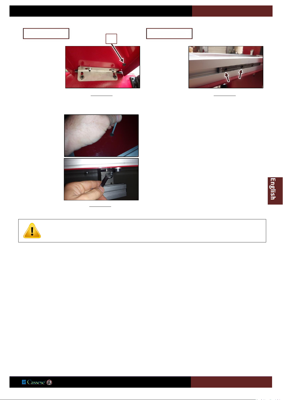
Tighten the screw
(H).
Figure 6-16
Left table side
H
Tighten the splint
(G).
Figure 6-17
Right table side
For each side, bring
the bracket under
the table and
tighten together
with screw (E
and
F).
Figure 6-18
Do not untighten screws of the moulding guide (factory setting).

USER MANUAL
CS969
25
ELECTRICAL CONNECTION
AIR LINE FITTINGS
Provide a supply pipe with an inside Ø of 8 that will withstand the maximum pressure of the source, which must not be less than 6
bar.
Source characteristics: dry air, no lubrication
The machine must be connected to air power supply between 6 and 8 bar.
Included with the machine
Supplied by the customer
The user must connect the power supply cable to a source complying with the regulations in force and protect
the machine by fitting fuses: 25 Amp aM for 220 Volt single-phase or 16 Amp aM for 380/220 Volt 3-phase.
Quick release (Q/R) Female
Air connector Z749.
Female quick
connector
Z749
standard connector - Z556
USA male quick connector - Z701
Figure 6-19
 Loading...