

Cassese CS 960 Instructions For Use Manual

Z15768
CS 960
Manual Operated Double-Mitre Saw 45°
Instructions for Use &
Technical Data
VERSION 2 - 09-2005
Cassese Communication

Left vertical clamp
handle
CS 960 DESCRIPTION
Blade carriage arms
Main case
Left vertical
clamp (option)
Left horizontal
clamp handle
Left horizontal
clamp
Left table
Left table support
bracket
Moulding guide
Right table
Main case handle
Right vertical clamp (option)
Right vertical clamp handle
Right table support
bracket
Cover safety screw
Electrical cabinet door
Foot locking nut
(x4)
Levelling foot (x4)
RIGHT SIDE OF MACHINE
Electrical
contactor
Isolation valve
Clamp control pedal
LEFT SIDE OF MACHINE
Extraction nozzles
Removable panel
Machine identity
plate
Offcut outlet
Air supply
A
TECHNICAL DATA
PRODUCT NAME CS 960
Year of creation 2005
Cutting capacity:
maximum width 160 mm
maximum moulding height 110 mm
Blade dimensions
Bore
Ø 350 mm
Ø 30 mm
Maximium cutting length: 1500 mm
Rotation speed: 2800 rpm (
Electrical power supply
Power cable, standard, section
230v Mono/ 30A 230vTRI/ 16A - 400vTRI/ 10A
3x 2.5 H07 RNF 3G2.5 4x 1.5 H07 RNF 4G1.5
50-60Hz) 3400 rpm (60Hz)
2 power motors (compliant with standard EN 60204 ) 1.5 kW
Extraction nozzle, ext. dia. 2x100 mm
Extraction compliant with standards: 28 m
3/s at 4 m for Ø 100
Air supply: 4 bar min. / 4 to 6 bar
Max. consumption: 2,3l / cycle
Weight 950 kg (# < 58) / 710 Kg (# > 57)
Noise ( compulsory ear protection) 85 dB
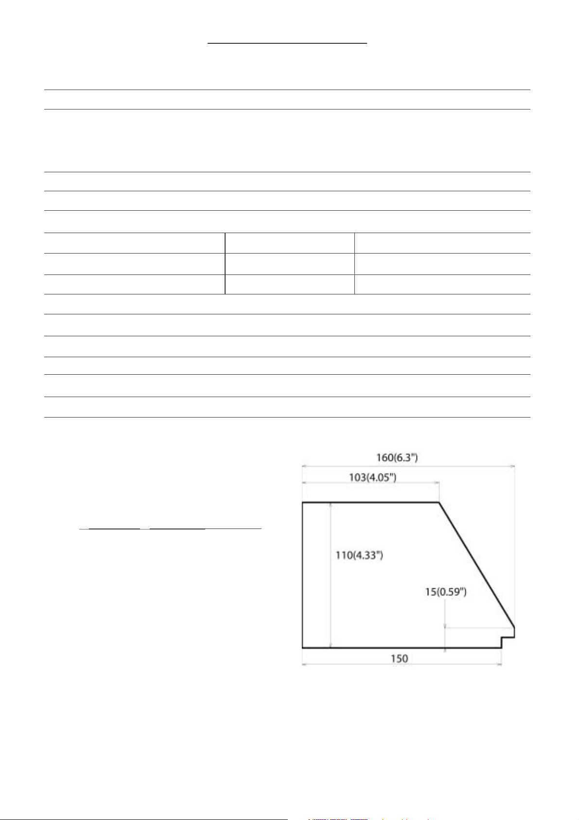
CUTTING CAPACITY (OVERALL)
for max. width = 160
Dimensions in mm
Options: - Right extension arm:
- Z15732 : 2 metres - Z15731 : 1,00 metres
- Digital measuring stop* (on request / Factor Adaptation):
- Z15736 : Smart Stop - Z15735 : Quick Stop
B

C

Contents
CS 960 DESCRIPTION A
TECHNICAL DATA B
CS 960 OVERALL DIMENSIONS C
I - INTRODUCTION 1
II - UNPACKING & HANDLING 2, 3
III - SETTING UP THE MACHINE
- Installing the right and left tables 4,5
- Electrical connections 6
- Air connections 6
- Dust extraction 6
IV - START-UP
- Control panel 6, 7
V - SAWING
- Horizontal clamp setting 7
- Vertical clamp setting 8
- First cut on the left 8
- Measuring the first piece 9
- Cutting the first piece 10
VI - PREVENTIVE AND CORRECTIVE MAINTENANCE
- Opening the main case 11
- Removing / refitting the blades 11
- Replacing the martyr cube 12
- Preventive maintenance / Troubleshooting 12
LIST OF WEARING PARTS
TECHNICAL DRAWINGS AND PARTS LISTS

I- INTRODUCTION
The CS 960 saw is used to produce 45° mitre cuts on all mouldings made
from solid or reconstituted wood, with or without coating (paint, varnish,
plastic, paper, metal leaf such as gold, bronze, aluminium, etc.).
It cannot be used for:
· Moulding profiles that do not have a 90° heel at least 5 mm high,
· Any metal profiles,
· Thin extruded plastic profiles:
(plastic cords, trimming, etc.).
Its two circular blades are driven by two electric motors
The moulding is clamped automatically by vertical (option) and horizontal
(standard) pneumatic cylinders.
A control, actuating the release of the blade carriage ensures operator safety
by keeping hands out of range of the blades.
The electrical control equipment is installed in a cabinet at the front of the
machine.
The pneumatic equipment is installed in the base and on the right-hand side
of the machine.
This machine was built to meet safety and hygiene requirements. It is
forbidden to modify the electrical and pneumatic equipment, remove
protective equipment installed on delivery or modify the machine safety
devices.
Saw CS 960 cannot be used by more than one operator at a time.
.
Residual Risks
Hands must never be inserted inside the main case as this contains the
clamping cylinders and rotating saw blades in their rest position.
For any other work inside the machine:
See the «Maintenance» section of this manual (page 11).
1
 Loading...