

Page 1
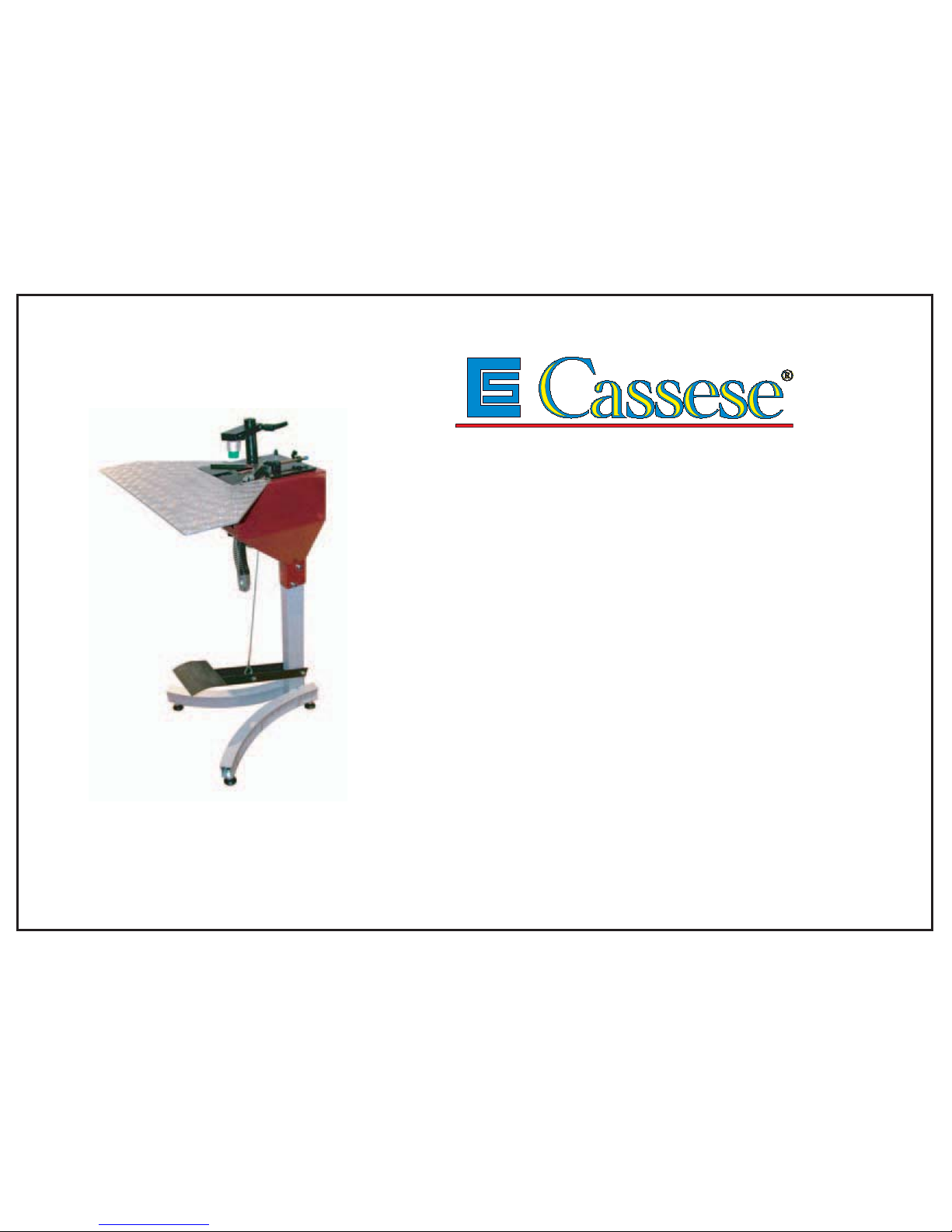
CS 59
Livro Tecnico de Instrucciones
Version 1 au 05 / 04
Cassese / Communication
ENSAMBLADORA FUNCCIONANDO CON PEDAL
Z 14053
ASSEMBLEUSE MECANIQUE A PEDALE
Manuel Technique et d’Utilisation
Technical and User Manual
FOOT OPERATED UNDERPINNER
Page 2
CASSESE CARTRIDGE WEDGE
MEANS OF ASSEMBLY
wedges . Since the beginning Cassese have seen that the most efficient, trouble-free way of using
the wedges was when they could be presented to the underpinner individually, this means without
glue that can cause jamming and technical problems in the underpinners when bonding agent is
accumulated.
This is why the wedges for Cassese underpinners come in disposable plastic cartridges in which
the wedges are individual, without glue, rust-protected and lubricated for smoother penetration
and for minimum wearing of your Cassese underpinner (frame joiner).
7
Manufactured with high quality steel
Cassese wedges are individual, without glue.
Rust-protected
Quick identification: The
cartridges are colour-coded
to identify the size of wedges
they contain
Special wedges for very
hard timbers are available.
Cartridges labelled HW
individually
Each cartridge contains a minimum of 275 to 290 wedges.
Thanks to the cartridges, you use 100 % of the wedges pur chased.
Lubricated for smoother
penetration and for minimum
wearing of your Cassese
underpinner (frame joiner)
Thanks to the cartridges, there are no parts to be changed or adjusted
on your underpinner (frame joiner), when you change the size to be used
Produced in respect of
international standards
the 10 COMMANDMENTS OF CASSESE CARTRIDGE WEDGE
1
2
3
4
5
6
8
9
POWER STRIP (patented)
All cartridge wedges* are produced
with a corrugation in the middle that
improves the resistance of the wedges
and make them join even harder
materials without difficulty.
(*except # 3, 4 and 5)
10
MEANS OF ASSEMBLY
WHETHER YOU ARE A CUSTOM OR VOLUME FRAMER,
JUST ASK US HOW THE CASSESE WEDGES IN CARTRIDGES
CAN MAKE YOU SAVE MONEY AND PRODUCE BETTER QUALITY FRAMES
Cassese are the inventors of the frame joining technique by underpinning with
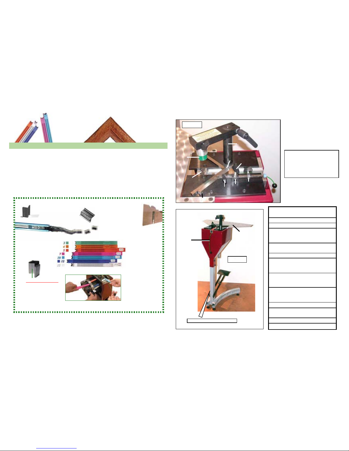
ANGLE ADJUSTMENT
SCREW AS
LIMIT STOP B
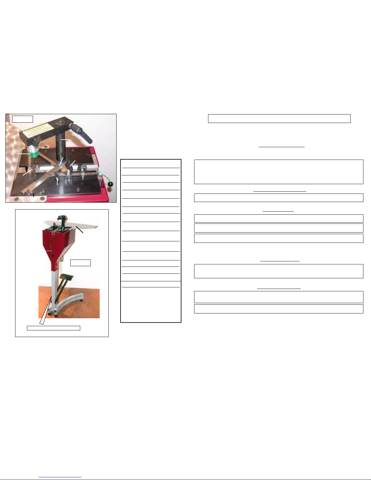
1
st
BACKFENCE B1
2
nd
BACKFENCE B2
90° JOINING ANGLE
ASSEMBLY E
WIRE FOR WEDGE
PUSHING SPRING F
WEDGE DISTRIBUTOR H
LEVER FOR
STAPLING POSITION
(inside of frame) P1
LEVER FOR
STAPLING POSITION
(outside of frame) P2
LEVER FOR ONLY
ONE OR INTERMEDIATE
POSITIONS P3
FOOT PEDAL P
TOP PRESSER
BRACKET Po
TOP PRESSER Pr
EXTENSION TABLE Ta
1
FS
F
H
P1
P2
Po
Pr
V
B
BP
B1
B2
P3
CS 59
F
OOT OPERATED
FRAME ASSEMBLING
MACHINE
AS
H
P1
P2
Po
Pr
B
B1
B2
E
P3
Fig N°1
F
St
Ta
P
WORK POSITION REFERENCE
St
Fig N°2
F
Ta
P
FRONT
St
Page 3
CS 59 - USER’S TECHNICAL MANUAL
INTRODUCTION 2
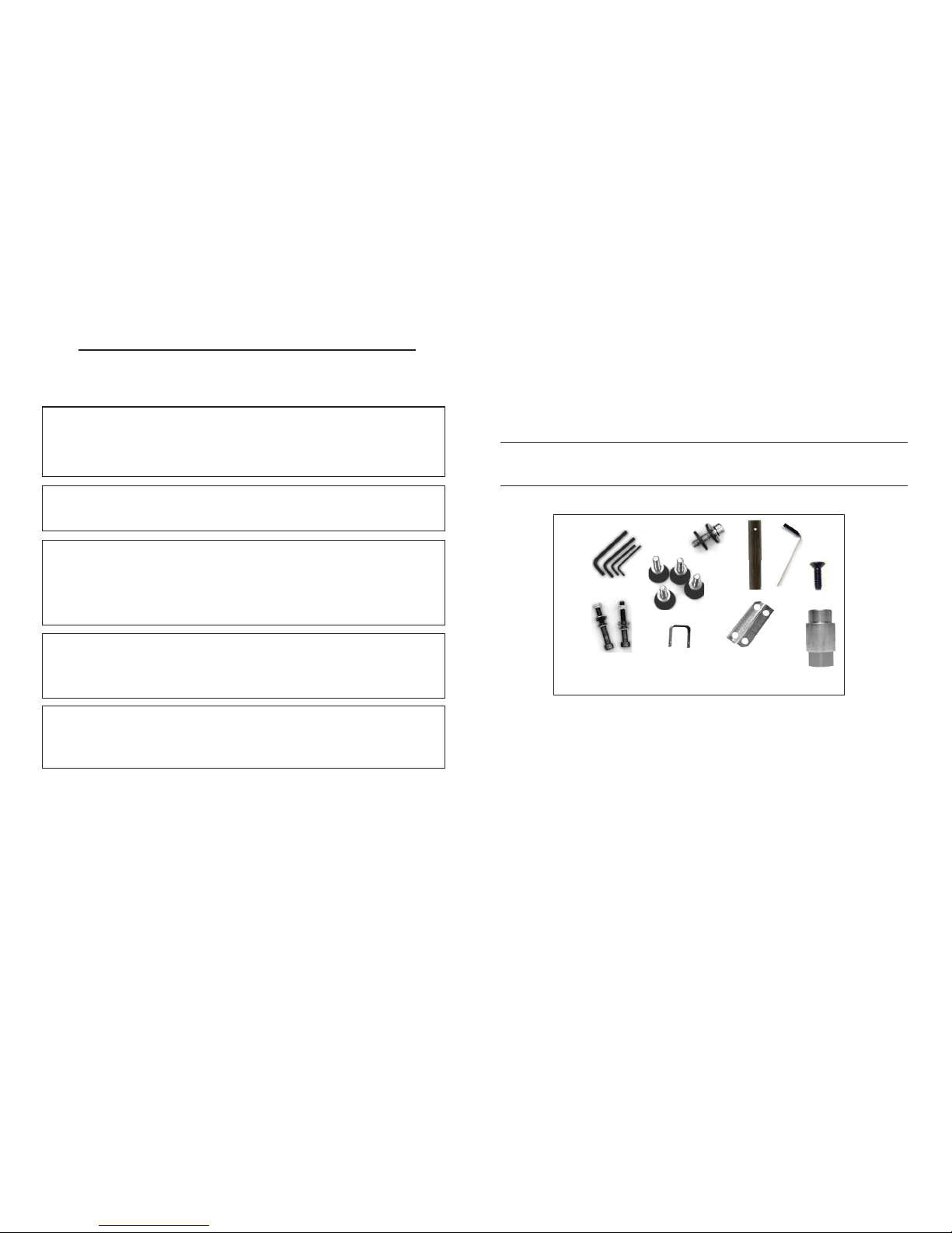
ACCESSORIES SUPPLIED WITH THE MACHINE
TECHNICAL SPECIFICATIONS
OPTIONS
GUARANTEE
PUTTING INTO OPERATION 3, 4, 5
REASSEMBLY
ADJUSTMENTS
SELECTION OF STAPLING POSITIONS 6
SETTING AND STORING THE STAPLING POSITIONS 6,7
SELECTION OF TOP PRESSER 8
ADJUSTMENT OF THE ASSEMBLY ANGLE 8
USE
MEANS OF ASSEMBLY 9
LOADING THE WEDGE CARTRIDGE ON MACHINE
JOINING THE FRAME
MAINTENANCE
LUBRICATION 10
CLEARING A WEDGE STUCK IN THE WEDGE DISTRIBUTOR 11
CONTENTS Page
2
INTRODUCTION
You have just bought a CS 59 frame joining machine, so we congratulate on your sensible
choice and thank you for your trust in Cassese products.
The CS 59 benefits from the experience of the joining machines that brought Cassese a
certain reputation. It makes it possible to join wooden mouldings of all profiles ( patent n°
7522814).
The CS 59 is designed to allow the operator to move all around the machine.
The joining operation is carried out by using metal wedges especially designed to perform
a tight join. These wedges come in throw-away plastic cartridges, without glue, individually lubricated and rust-protected for the toughest challenges.
IMPORTANT : You should not use other wedge cartridges than those manufactured by
Cassese and marketed by official Cassese distributors (registered mark CS).
BEWARE OF COPIES.
ACCESSORIES SUPPLIED WITH THE MACHINE
TECHNICAL SPECIFICATIONS OF CS 59
Minimum moulding width : 3mm (1/8”) Minimum moulding height : 7 mm (¼”)
Maximum moulding width :
f
Maximum moulding height : 80 mm ( 3”1/4 )
Furthest stapling position from back of moulding (at 45°) : 74 mm (3”)
Wedge sizes in cartridges of 275 pieces : 3, 4, 5, 7, 10, 12 and 15 mm.
Two wedge types : for soft and for hardwoods.
Machine gross weight : 22 kg (47 lbs)
Dimensions : 493mm(19''2/5) x 600mm (23''2/3)(w/out extension table)
1095 mm high (43'' 1/10)
GUARANTEE
One year guarantee for parts and labour against manufacturing defects. Wear parts and
those damaged as a result of non appliance with the instructions of the present manual are
excluded from the guarantee.
6, 5, 4, 3 mm
x4
+ 1 Table + 1 Foot pedal + 1 Support + 1 Short green rubber for hardwood
Page 4

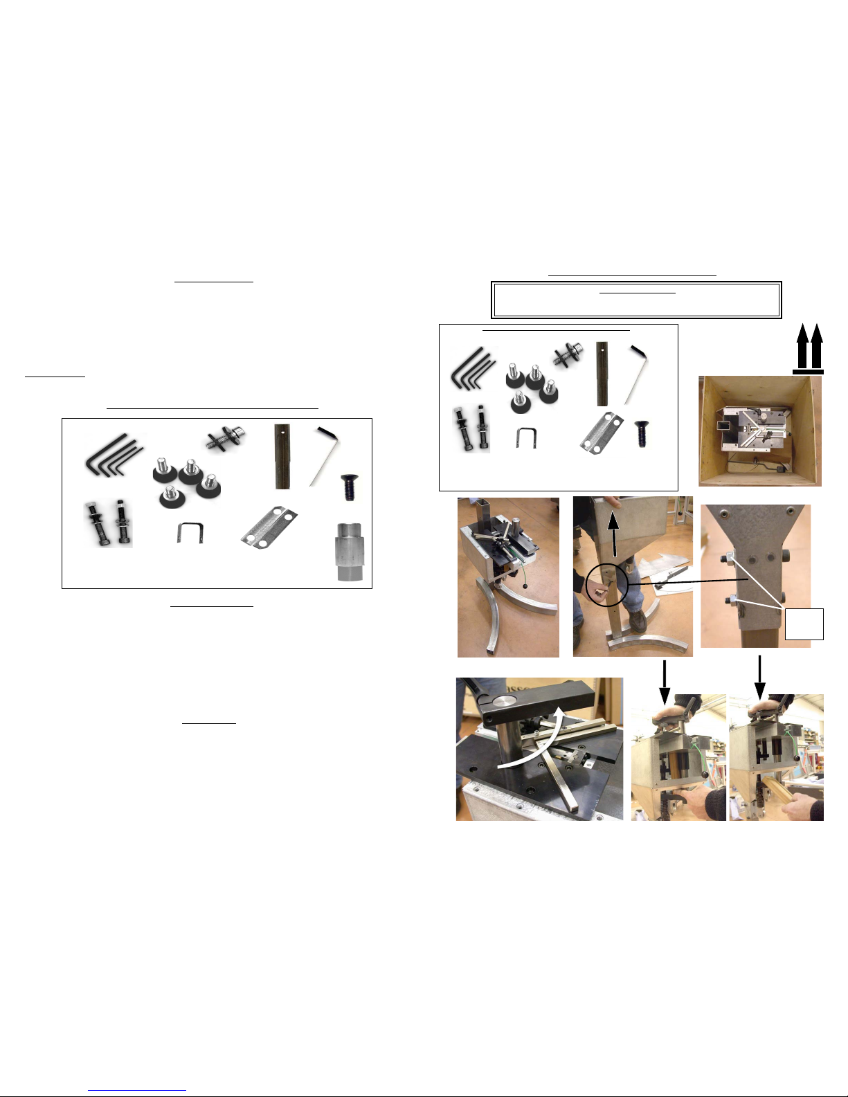
PUTTING INTO OPERATION
ACCESSORIES SUPPLIED WITH THE MACHINE
Keep the package of
the machine so, that
the arrows drawn on
the outside stand up,
12
3
4
5
6
13 mm
Wrench
6, 5, 4, 3 mm
x4
fig. 3
pag..3
fig. 9
fig. 12
fig. 13
+ 1 Table + 1 Foot pedal + 1 Support + 1 Short green rubber for
hardwood
3
WARNING
REMOVE THE TWO LATCH-TIGHTENING SCREWS UNDER THE CASE.
7
8
4 mm
10
allen
Key
6 mm
CABLE
11
10
a
b
c
d
a
b
c
d
12
x4
x4
4
Page 5
2
4 mm
x 4
1
4 mm
x 4
3
CS 59/79
Z 3585
!
-S/E TABLE
-S/A TABLE EXTENSION
-MESA DE EXTENSION
-U-GR. TISCHVERLANGERUNG
13
19 mm Wrench
5
!
50 MM
MINIMUM
50 MM BETWEEN
THE SUPPORT OF
FOOT AND THE
GROUND.
ADJUSTMENTS
6
2 mm MINIMUM
2 mm MINIMUM
P 1
P2
P3
B1
90° JOINING ANGLE ASSEMBLY
B
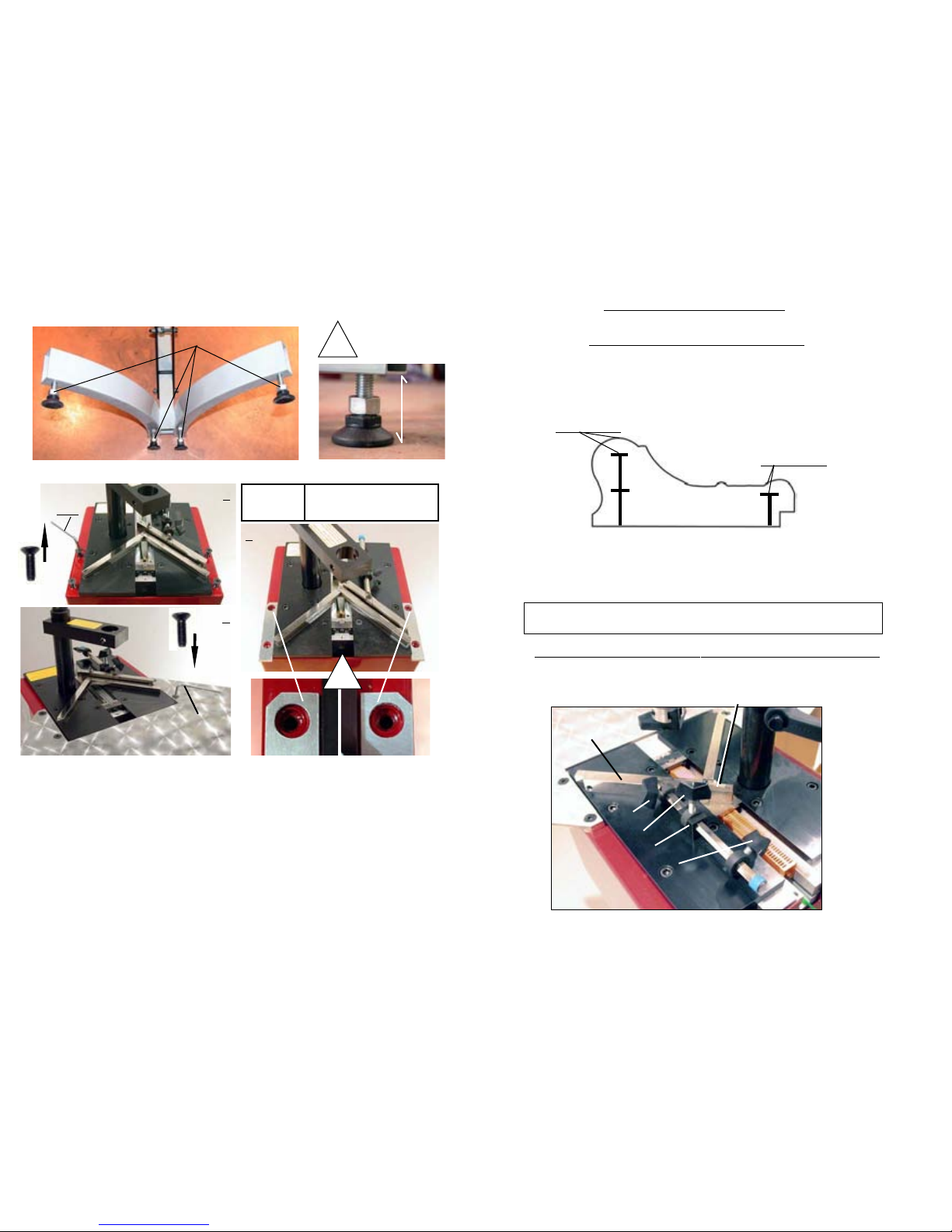
As a general rule a MINIMUM 2 mm clearance (less than 1/8”) above the wedges shall
be respected.
Same sized wedges can be stacked in order to avoid to have to change the cartridge size
when joining frames with different thickness.
AS A GENERAL RULE, THE JOINING MUST BE CARRIED OUT AS
CLOSE TO THE THICKEST MOULDING PART(S) AS POSSIBLE .
SELECTION OF STAPLING POSITIONS
The CS 59 is designed to join mouldings in one or two places (positions) without limitation of the
number of wedges in any of those places. The selection depends on the width and thickness of the
moulding to join.
SETTING AND STORING THE STAPLING POSITIONS
Unlock the stapling position lock handles P1, P2 and P3.
(Approx.1/8’’)
(Approx.1/8’’)
Page 6
WEDGE
EXIT
WEDGE
EXIT
FRONT OF MACHINE
P2
B
P1
P3
B1
B2
B
E
E
E
7
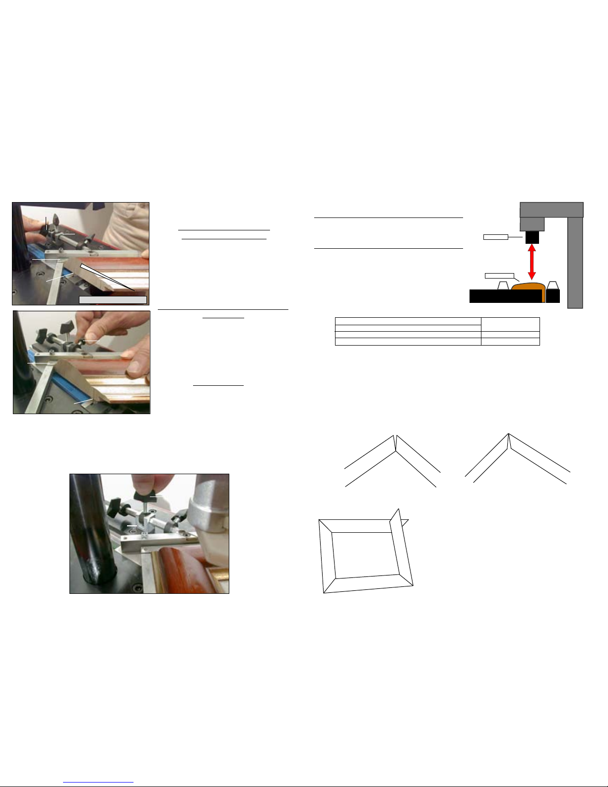
Standing in the work position used of reference for explanations (behind the machine; see
Fig 2, page 1), with your left hand, put the first moulding chop in front of the left (1
st
)
backfence B1 and bring the chop in contact
with the right (2
nd
) backfence B2.
For the stapling position close to the inside
of the frame :
Move the 90° joining angle backwards, until
you have reached the furthest
position to the inside of the frame where you
want to insert wedge(s).
Then bring the lever P1 against the limit stop
B and tighten the lever.
Now the two positions of joining are set and
the machine’s 90° angle can move only
within the limits of these two positions.
In case you would like to insert wedges in between these two positions, or if you are
working with a very small moulding and would like to insert wedges only in one place, you
can use the lever P3 located on the limit stop B.
This intermediate lever P3 also enables you to stack wedges (on top of each other in the
same position) without risk of missing the stacking operation (not pushing the first wedge
deeper inside).
For the stapling position close
to the outside of the frame :
Move forward the 90° joining angle assembly
E until the place where you want to insert the
wedge(s) has been reached by the WEDGE
EXIT (see picture). Then bring the lever P2
against the limit stop B and tighten it.
If the corner is open towards outside, unscrew (turn anti-clockwise) the angle adjustment
screw AS (see Fig 1 page 1) a little to correct the fault and check again.
ADJUSTMENT OF THE ASSEMBLY ANGLE
If several cutting machines are being used in your production or if you receive your
mouldings already cut by your suppliers (chop service), the angles of the mouldings will
be slightly different from one cutting machine to the other. The joining angle of your CS
59 can be adapted to find precisely the cutting angle of your cutting machine.
If the corner is open towards inside, screw in (turn clock-wise) the angle adjustment screw
AS (Fig 1 page 1) to correct the fault.
If you get this result, check your cutting angle, which is wrong
in this case because it is less than 45°.
Carry out the adjustment of the angle of your cutting
machine.
IT IS IMPOSSIBLE TO MAKE A RECTANGLE
FRAME WITH ANGLES SMALLER THAN 90°.
Outside
Inside
8
Make sure that the distance between the moulding’s top
and the presser’s bottom is not more than 30 mm (1 ¼”).
If the distance is bigger than this, use another (longer)
top presser to reduce the distance.
PRESSER
MOULDING
30 mm (1 1/4’’)
MAXIMUM
SELECTION OF A TOP PRESSER END
Triangle top pressers are good for flat mouldings
or for mouldings presenting a flat or horizontal
area to come down on. The green or orange rubber
ends are good for complicated forms (uphill,
downhill or reverse mouldings).
BLACK TRIANGLE PRESSER FOR HARDWOODS Fixing in support with
WHITE TRIANGLE PRESSER FOR SOFT WOODS 2.5 mm Allen key.
GREEN ROUND RUBBER ENDS FOR HARDWOODS 1 long and 1 short
YELLOW ROUND RUBBER ENDS FOR SOFT WOODS 1 long and 1 short
Page 7
9
JOINING THE FRAME
USE
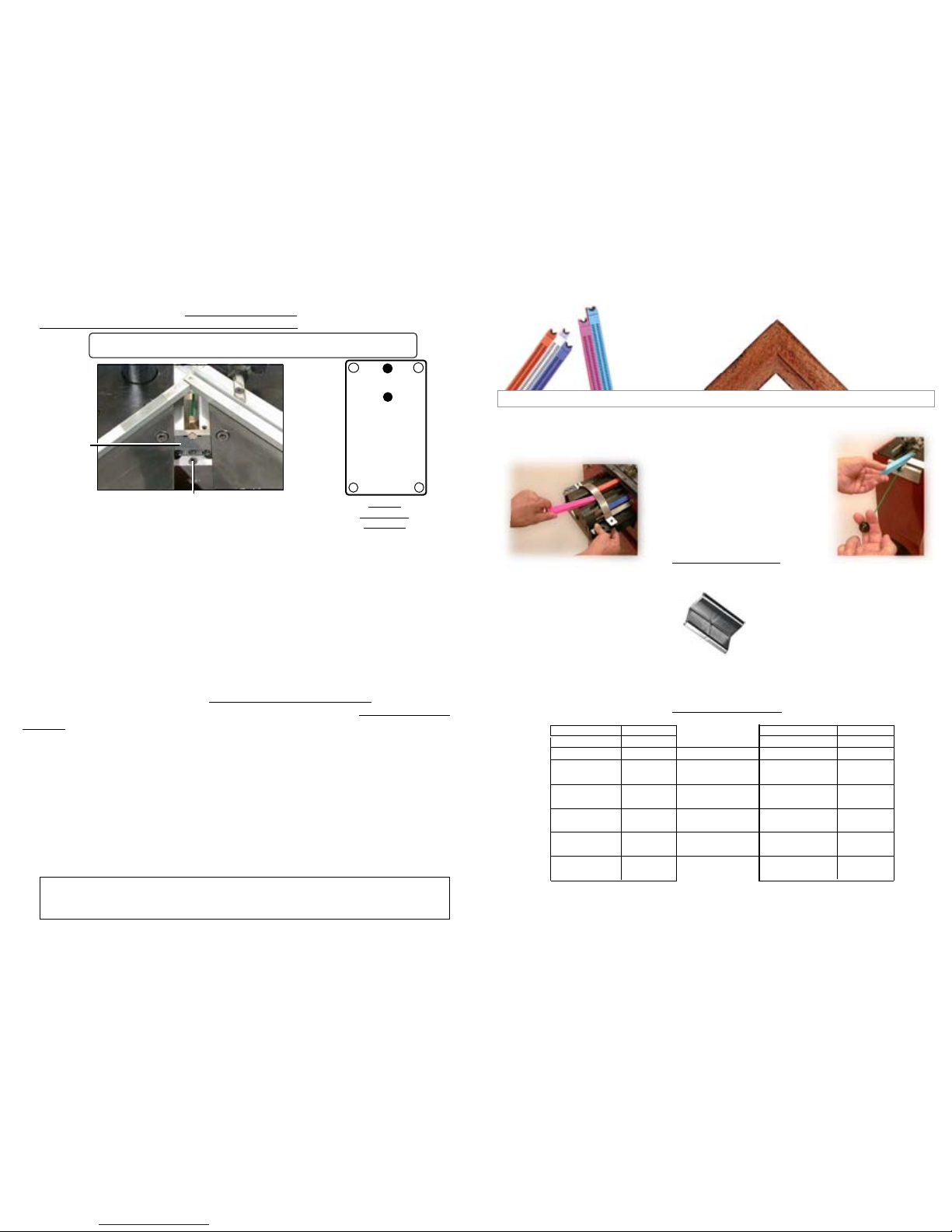
LOADING AND CHANGING THE WEDGE CARTRIDGE ON MACHINE
Pull the wire with ball of the wedge pusher spring F (fig.2, p1) fully out.
If there is a cartridge on machine, holding the wire pulled out, r emove it by simply sliding out
the cartridge.
Holding the wire pulled out, put a new cartridge on machine and pay attention that it is fully
inserted in the wedge distributor’s window.
Release gently the wire with ball of the wedge pusher spring F.
The joining is performed by using metal wedges, a Cassese inven-
tion, designed to ensure very tight corners. Seven sizes are available :
3, 4, 5, 7, 10, 12 and 15 mm. They come in throw-away cartridges
that are colour-coded per size for easy identification. Cartridge
wedges exist in two versions : NORMAL for soft and normal timbers
and HW for very hard timbers. These hardwood wedges are
to be
used only on hardwoods. Your CS 59 machine is designed to use all
sizes of Cassese cartridges without having to change any parts on the
machine or having to adjust anything.
For the long term performance and reliability of your CS 59, only use
genuine CASSESE cartridge wedges. Beware of counterfeit products.
MEANS OF ASSEMBLY
After selecting and setting the stapling positions (page 6 & 7), adjusting the assembly
angle (page 8), checking the distance between the top presser and the moulding (page 8)
and loading the best suited type (normal or hardwood) and size of wedges (page 9),
1- Put the first (left-hand) moulding in front of the fence B1 and push it so that its mitre en d
reaches the other fence B2.
2- Holding it so, put the second moulding chop against fence B2 and slide it until it reaches the
first moulding.
3- Holding the mouldings in place against each other, hold the backfences B1 & B2 with your
thumbs and make the angle assembly slide backwards until the lever P1 reaches the limit stop B.
You can eventually tighten the intermediate lever P3 to be sure that the position remains fixed.
4- Still holding the mouldings well profiled against each other, push the foot pedal P (Fig 2,
p.1) . If you intend to stack a second (or third) wedge in the same position, just push the
footpedal again. In this case using (tightening) the lever P3 will enable you to stack them more
easily.
5- If there is a second stapling position chosen (with lever P2), just repeat the same operation
by pushing forward the mouldings and the angle assembly of the machine until P2 reaches the
limit stop B. And repeat step 4 above.
10
MAINTENANCE
6mm MAXIMUM ( 1/4’’ )
WEDGE REMOVING TOOL
DISTRIBUTOR
( BLOCK H )
WEDGE EXIT
1) LUBRICATION
Periodically, remove the wedge distributor (Fig 1, block H) and clean it (by air gun).
It is recommended to lubricate the hammer (driver blade) periodically. To do so, remove the
wedge distributor (blockH) and put a small quantity of grease in the bottom hole of the wedge
distributor. The hammer will be lubricated every time it crosses the wedge distributor.
2) CLEARING OF A WEDGE STUCK IN THE WEDGE DISTRIBUTOR
If you push the foot pedal half way and release, a wedge may be half engaged in the wedge
distributor. In this case,
- Try to remove the cartridge that is in position. If it resists, use the wedge removal tool to push
down the wedge back in the cartridge.
- Pay attention not to make penetrate the tool more than 6mm (¼”) into the wedge distributor.
It is important not to leave a wedge half engaged in the wedge distributor, as it may cause the
insertion of two wedges when you join the next corner or may cause the jamming of the
hammer (the driver blade) in the wedge distributor.
- In case of the hammer (driver blade) jamming with a wedg e in the wedge distributor, see the following section (3).
Page 8
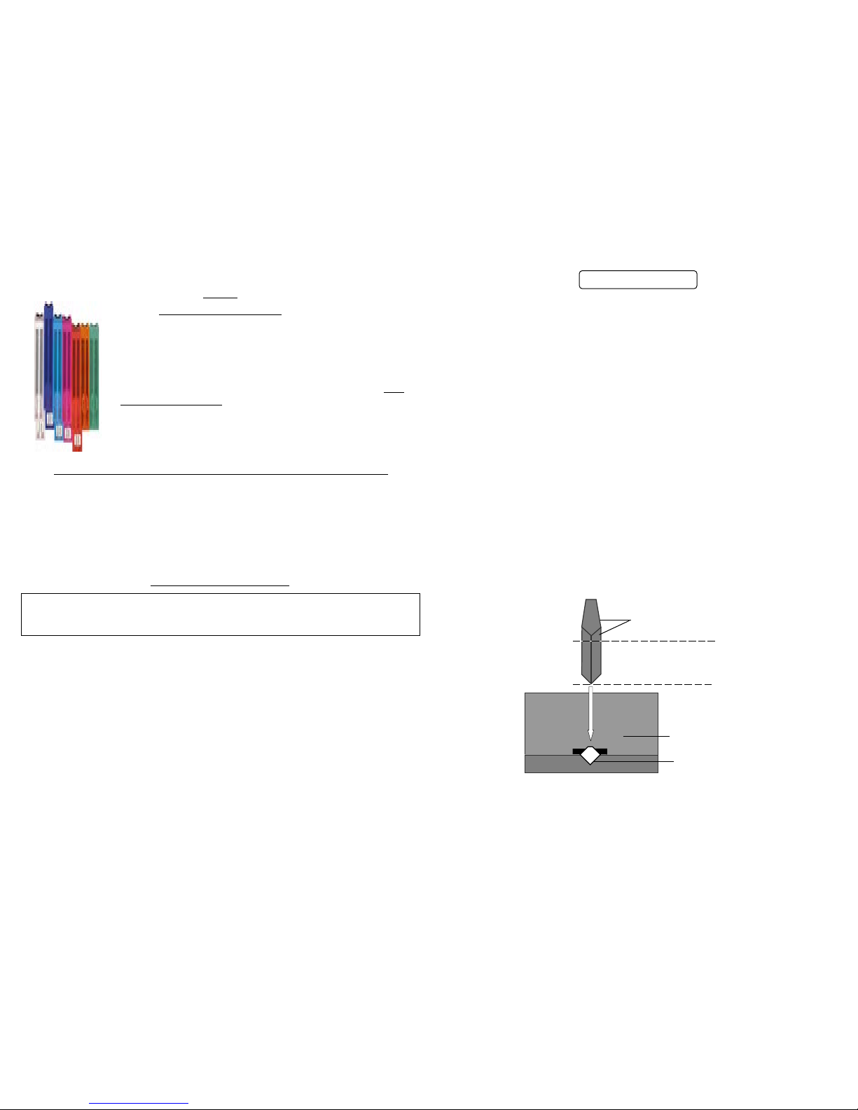
MAINTENANCE
AFTER EACH INCIDENT, IF THE HAMMER STAY JAMMED IN BLOCK H,
YOU SHOULD HAVE TO CHANGE IT
A
BC
D
GF1
GF2
- Remove the cartridge that is on machine, and the top presser.
- Using the 3mm Allen key, loosen the locking screw of the wedge distributor Block H.
- Then lift the top presser’s bracket arm by hand. The wedge distributor will come out of its
housing.
- Remove it from the machine.
- The old hammer (wedge driver blade) is stuck in the wedge distributor : first try to remove it
with a pair of pliers. If not possible, remove the four screws (A, B, C, D) and open the block
H.
- Remove the old hammer. Assemble the Block H back again.
Putting a new hammer (driver blade) :
- Put a drop of grease in the bottom hole of the wedge distrib utor (block H).
- Insert a new hammer into block H with
the hole of the hammer downwards.
- Re-position the wedge distributor in its housing on the machine with the
window towards the
cartridge.
- If the upper end of the hammer stays out of the block H, push it fully in with a piece of wood or
moulding.
While keeping the moulding in place (on block H) and pressing on it, pull up the top presser’s
bracket arm Po (Fig1 p1) with a quick movement.
The new hammer must have taken its position in the mechanism automatically.
- Check with your finger that the block H does not stay out of the machine (higher than the work
level) and tighten the locking screw of block H. No need to tighten too much.
- The machine is ready to work again.
SCREW
POSITIONS
BLOCK H
3 ) IN CASE OF HAMMER AND WEDGE JAMMING
LOCKING SCREW
WEDGE
DISTRIBUTOR
(BLOCK H)
11
If you have any difficulty to remove the block H from the machine, push down with
your hands the top presser’s bracket arm.
This should free the block H that is stuck with the hammer.
AGRAFES EN W
Cassese Communication 01 / 2002
AGRAFES ASSEMBLEUSES CS
De conception originale, utilisée sur toutes nos assembleuses,
AGRAFES EN W
L’agrafe en w brevetée Cassese
®)
vous permettra d’obtenir un serrage
parfait de vos assemblages grâce à
sa déformation lorsqu’elle pénètre
dans le bois.
Suivant le type de bois utilisé, vous
choisirez la version :
Bois Normal (7 hauteurs disponibles)
ou Bois Dur (5 hauteurs disponibles).
Chargement du barillet de la CS 4095
Chargement de la CS 59
AGRAFES INDEPENDANTES, SANS COLLE, EXEMPTES DE LIANT : PAS D’ENCRASSEMENT MACHINE.
IDENTIFICATION RAPIDE DES HAUTEURS D’AGRAFES PAR LA COULEUR DU CHARGEUR.
IDENTIFICATION CHARGEURS VERSION «BOIS DUR» PAR ETIQUETAGE .
PRODUITS CONFORMES AUX NORMES INTERNATIONALES .
FABRICATION EN ACIER DE QUALITE SUPERIEURE
LUBRIFIEES POUR FACILITER LA PENETRATION DANS LE BOIS.
MISE EN PLACE ET DECHARGEMENT DU CHARGEUR : FACILE, RAPIDE, PRECIS, SANS PERTES .
TRAITEMENT ANTI - CORROSION.
CONDITIONNEES EN CHARGEURS JETABLES D' ENVIRON 275 AGRAFES
.
AUCUN REGLAGE MACHINE POUR LES CHANGEMENTS DE TAILLE
30403NCOI 3 mm
30404NCOI 4 mm
304 05 NCOI 5 mm
314 05 BDCO 5 mm BD
304 07 NCOI 7 mm
314 07 BDCO 7 mm BD
304 10 NCOI 10 mm
314 10 BDCO 10 mmBD
304 12 NCOI 12 mm
314 12 BDCO 12 mmBD
304 15 NCOI 15 mm
314 15 BDCO1 15 mmBD
Boites de 6 chargeurs de 275 agrafes Boites de 40 chargeurs de 275 agrafes
(1650 agrafes / boite) (11000 agrafes / boite)
REFERENCE TYPE REFERENCE TYPE
30303NCOI 3 mm
30304NCOI 4 mm
30305NCOI 5 mm
31305BDCO 5 mmBD
30307NCOI 7 mm
31307BDCO 7 mmBD
30310NCOI 10 mm
31310BDCO 10 mmBD
30312NCOI 12 mm
31312BDCO 12 mmBD
30315NCOI 15 mm
31315BDCO 15 mmBD
VERT
ORANGE
ROUGE
MAGENTA
CYAN
BLEU
BLANC
Page 9
1
F
St
Ta
P
POSITION DE REFERENCE
AS
H
P1
P2
Po
Pr
B
B1
B2
E
P3
Fig N°1
St
Fig N°2
F
Ta
P
AVANT
FIL POUSSOIR D’AGRAFES
REGLAGE ANGLE
ASSEMBLAGE
CS 59
ASSEMBLEUSE
MECANIQUE
AS
B1
B2
2
EME
BUTEE
F
Po
H
P2
P1
Pr
POTENCE
BUTEE POSITION
INTERIEURE
DISTRIBUTEUR D’AGRAFES
PRESSEUR
BUTEE POSITION
EXTERIEURE
P3
BUTEE
POSITION INTERMEDIAIRE
TABLE DE TRAVAIL
Ta
PEDALE
P
EQUERRE COULISSANTE
E
1
ère
BUTEE
BUTOIR
B
S
OMMAIRE
INTRODUCTION
ACCESSOIRES FOURNIS AVEC LA MACHINE
SPECIFICATIONS TECHNIQUES
OPTIONS
GARANTIE
DEBALLAGE , MONTAGE
LUBRIFICATION
DEGAGEMENT D’UNE AGRAFE ENGAGEE DANS LE DISTRIBUTEUR
DESENRAYEMENT
2
3,4, 5
6
6,7
9
10
11
MAINTENANCE
MISE EN SERVICE
LE MOYEN D’ASSEMBLAGE
CHARGEMENT ET CHANGEMENT DU CHARGEUR D’AGRAFES
ASSEMBLAGE DU CADRE
REGLAGES
ASSEMBLAGE
CS 59 - MANUEL TECHNIQUE & D’ UTILISATION
SELECTION DE LA POSITION D’AGRAFAGE
MEMORISATION DES POSITIONS D’AGRAFAGE
CHOIX DU PRESSEUR
REGLAGE DE L’ANGLE D’ASSEMBLAGE
8
Page 10
INTRODUCTION
Vous venez d’acquérir une CS 59. Nous vous félicitons pour votre bon choix et nous vous
remercions pour votre confiance.
La CS 59 bénéficie de l’expérience des assembleuses qui ont fait la notoriété de Cassese.
Elle permet l’assemblage des moulures en bois de tous profils (Brevet n’ 7522814)
La CS 59 est conçue pour permettre à l’opérateur de se déplacer tout autour de la machine.
L’assemblage est réalisé par des agrafes métalliques spécialement étudiées pour un serrage
parfait.
IMPORTANT : Ne pas utiliser d’autres chargeurs que les chargeurs Cassese (Marque déposée CS)
2
GARANTIE
La CS 59 est garantie l an, pièces et main d’oeuvre contre tous vices de fabrication. Les
pièces d’usure et celles endommagées par une utilisation non conforme aux dispositions
de la présente notice sont exclues de cette garantie.
SPECIFICATIONS
- Largeur minimum de la moulure : 3 mm Largeur maximum de la moulure : infini .
- Hauteur minimum de la moulure : 7 mm Hauteur maximum de la moulure : 80mm .
- Distance maximum du point d’agrafage jusqu’au dos de la moulure (coupe à 45°) : 74 mm.
- Taille des agrafes en conditionnement de 275 : 3, 4, 5, 7, 10, 12 et 15 mm .
- Deux types d’agrafes : bois tendres, bois durs .
- Poids de la machine : environ 22 kgs .
- Encombrement : 493 mm x L 600 mm (sans table de travail) x H 1095 mm
ACCESSOIRES FOURNIS AVEC LA MACHINE
6, 5, 4, 3 mm
x4
+ 1 Table d‘extension + 1 Pédale + 1 Support presseur cylindrique
+ 1 Presseur élastomère vert cylindrique 30 mm pour bois dur
MISE EN SERVICE
ACCESSOIRES INCLUS AVEC LA MACHINE
La caisse doit être posée
au sol de telle manière que
les flèches soient orientées
vers le haut.
12
3
4
5
6
Clé plate
de 13 mm
6, 5, 4, 3 mm
x4
fig. 3
pag..3
fig. 9
fig. 12
fig. 13
+ 1Table d‘extension + 1 Pédale + 1 Support presseur cylindrique
+ 1 Presseur élastomère vert cylindrique 30 mm pour bois dur
3
TRES IMPORTANT
OTEZ LES DEUX VIS DE BLOCAGE TRANSPORT
SE TROUVANT SOUS LA CAISSE .
Page 11
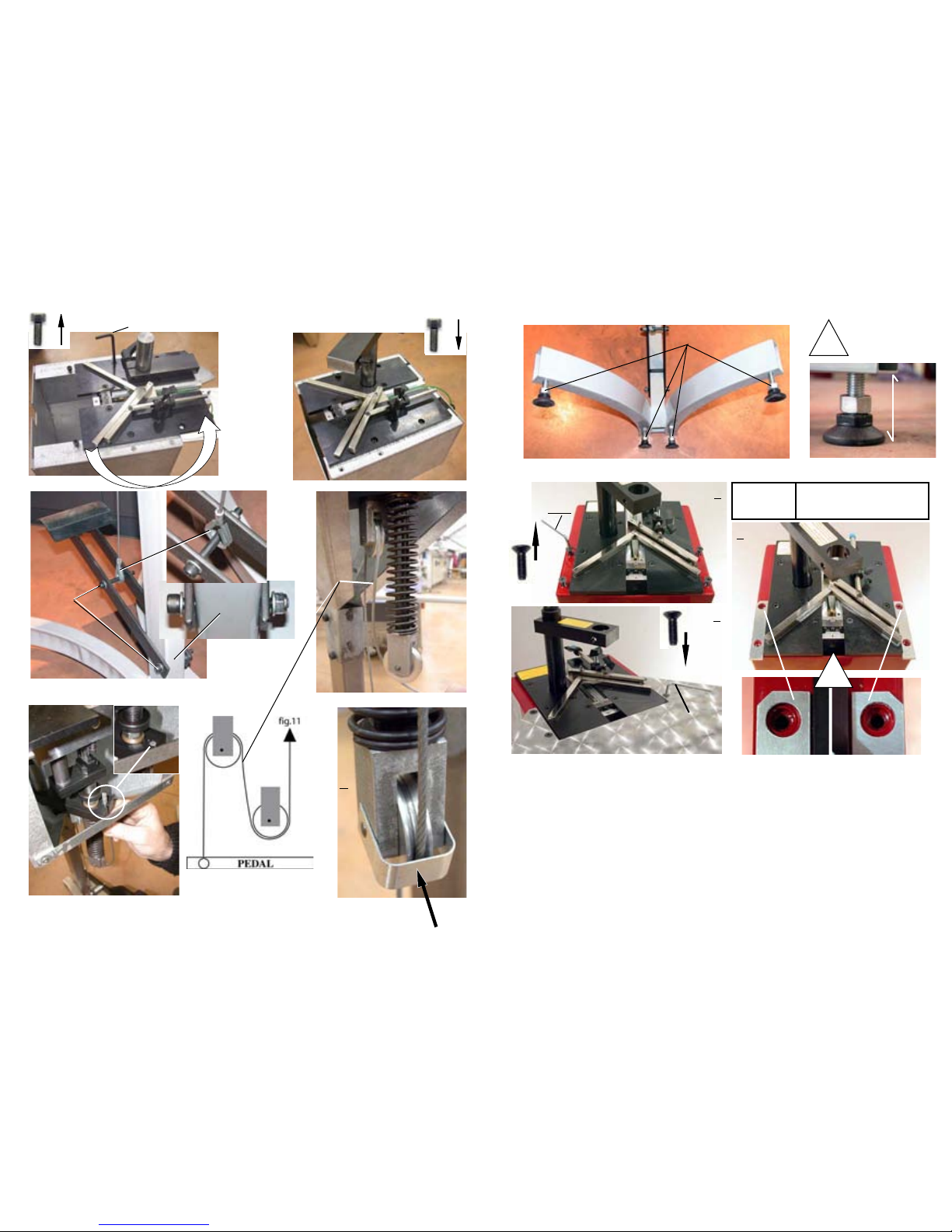
7
8
4 mm
10
Cle
allen
6 mm
CABLE
11
10
a
b
c
d
a
b
c
d
12
x4
x4
4
E
2
4 mm
x 4
1
4 mm
x 4
3
CS 59/79
Z 3585
!
-S/E TABLE
-S/A TABLE EXTENSION
-MESA DE EXTENSION
-U-GR. TISCHVERLANGERUNG
13
Clé Plate de 19 mm
5
!
50 MM
MINIMUM
50 MM ENTRE LE
SUPPORT DE PIED
ET LE SOL.
Page 12
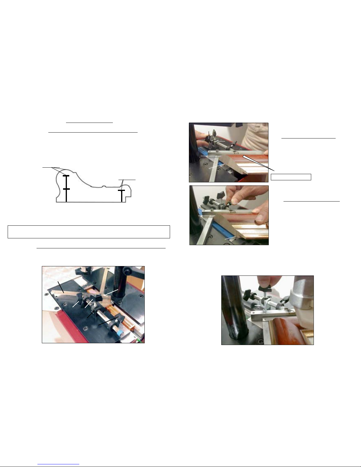
SELECTION DE LA POSITION D’AGRAFAGE
La CS 59 est prévue pour procéder à l’agrafage des moulures à 1 ou 2 endroits sans limi-
tation du nombre d’agrafes à chacun de ces emplacements .Le choix sera fait en fonction
de la largeur de la moulure à assembler et de son épaisseur. Il est possible, toutefois , d’in-
sérer des agrafes entre ces deux positions .
On prévoit , en règle générale une garde de 2 mm MINIMUM au dessus de l’agrafe
.
Des agrafes de même dimensions peuvent se superposer , ceci pour éviter de changer le
chargeur d’agrafes si l’on réalise des assemblages de cadres d’épaisseur diverses .
NB : DANS TOUS LES CAS, L’AGRAFAGE DOIT S’EFFECTUER LE PLUS PRES
POSSIBLE DE LA (OU DES) PARTIE (S) LA PLUS HAUTE DE LA MOULURE .
REGLAGES
Débloquez les butées de position d’agrafage P1 , P2 et P3 .
MÉMORISATION DES POSITIONS D’AGRAFAGES
6
15mm
15mm
2 mm MINI-
2 mm MINI-
15 mm
P 1
P2
P3
B1
Equerre
Coulissante
B
Deuxième position d’ agrafage :
Côté intérieur du cadre :
Déplacez l’équerre coulissante vers l’arrière ,
jusqu’à la position d’agrafage choisie,
amenez la butée P1 en butée contre le
butoir B et la bloquer.
Dans le cas ou l’on veut une ou plusieurs positions intermédiaires ou une position unique, on
peut immobiliser positivement l’équerre coulissante E au moyen de la vis de blocage P3
située sur le butoir B .
( L’ empilage des agrafes est facilité par le blocage de l’équerre coulissante E avec la vis P3 )
Première position d’agrafage :
Côté extérieur du cadre :
Déplacez l’équerre coulissante E vers l’avant
jusqu’à la position d’agrafage choisie.
Amenez la butée P2 contre le butoir B et
la bloquer .
SORTIE
AGRAFES
SORTIE
AGRAFES
AVANT MACHINE
P2
B
P1
P3
Positionnez la 1ère moulure contre la butée B1 et la faire glisser jusqu’à la butée B2
B1
B2
B
E
E
E
7
Page 13
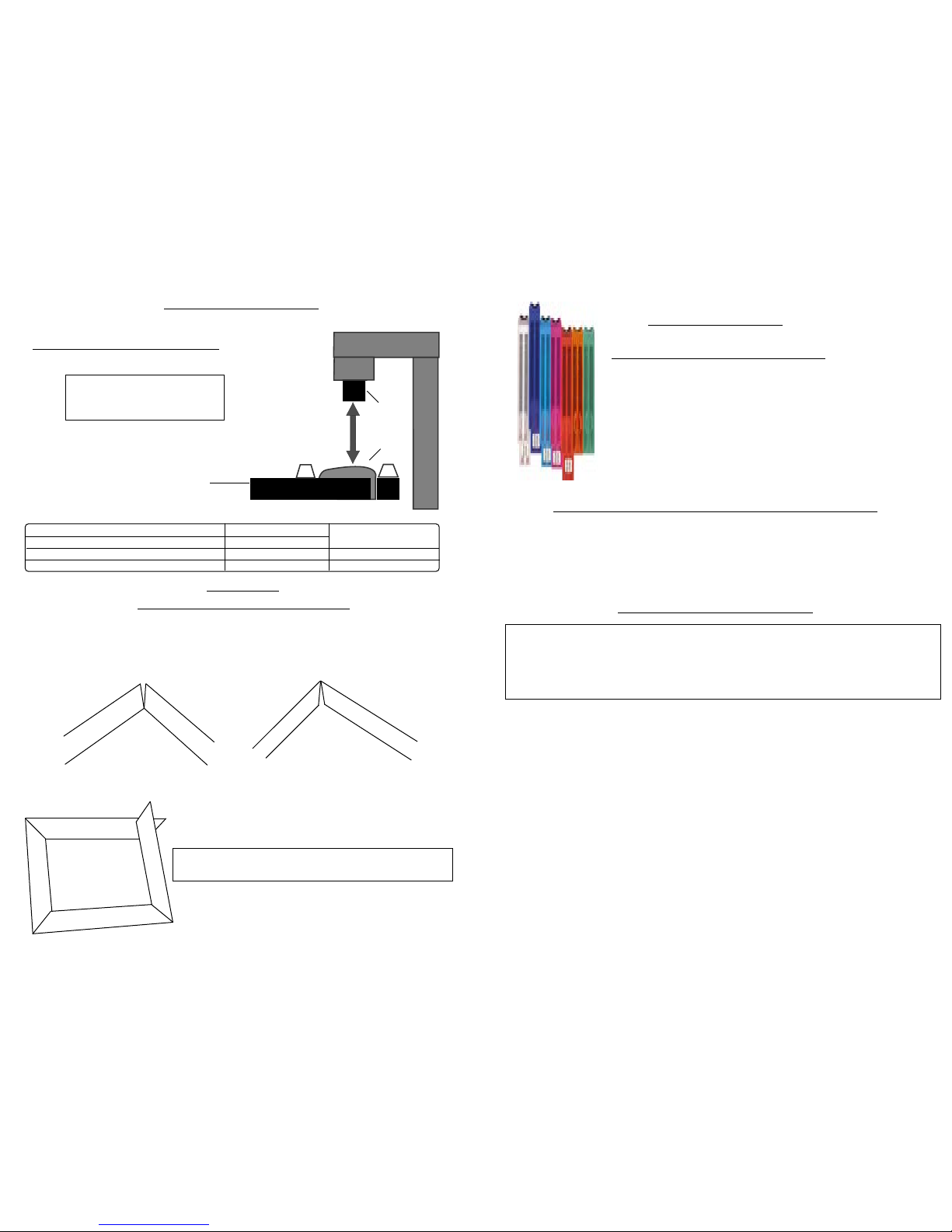
PRESSEUR NOIR BOIS DURS
PRESSEUR BLANC BOIS TENDRES
EMBOUTS « ELASTOMERE VERT » BOIS DURS 30 et 45 mm
EMBOUTS « ELASTOMERE JAUNE » BOIS TENDRES 30 et 45 mm
30 mm
MAXIMUM
POSITIONNEMENT DU PRESSEUR
Dans le cas contraire utilisez l’embout correspondant :
Vérifiez que la course entre le
haut de la moulure et le bas du
presseur ne dépasse pas 30 mm .
Presseur
Moulure
CHOIX DU PRESSEUR
8
REGLAGE
DE L’ANGLE D’ASSEMBLAGE
Si l’angle est ouvert sur l’extérieur , Dévissez la vis de réglage de l’angle d’assemblage AS
(Fig 1p1 ) pour corriger le défaut et vérifiez le réglage en serrant les moulures contre les
butées .
Si l’angle est ouvert sur l’intérieur, Vissez la vis de réglage de l’angle d’assemblage AS
(Fig 1p1) pour corriger le défaut et vérifiez le réglage en serrant les moulures contre les
butées .
Si vous obtenez ce résultat , vérifiez votre angle de coupe
qui dans ce cas , est mauvais car inférieur à 45 ° .
Extérieur
Intérieur
EQUERRE COULISSANTE
Montage sur support
clé hexagonale de 2,5
9
Les points d’agrafage sont mémorisés (voir Mémorisation des points d’agrafage page 6,7).
L’angle d’assemblage à été vérifié.( voir Réglage de l’angle d’assemblage page 8) .
La course entre le haut de la moulure et le bas du presseur ne dépasse pas 30 mm .
(Voir Choix du presseur page 8).
La bonne taille d’agrafe (bois normal ou bois dur) à été chargée dans la CS 59.
Positionnez la 1ère moulure contre la butée B1 et la faire glisser jusqu’à la butée B2
(fig 1 p1).
Toujours en maintenant la première moulure, positionnez la 2ème moulure contre la butée
B2 , puis la faire glisser jusqu’à ce qu’elle entre en contact avec la première.
En faisant glisser l’équerre coulissante vers l’avant ou l’arrière amenez P2 ou P1 en butée
contre B . Eventuellement bloquez P3 .
Toujours en maintenant les moulures, enfoncez la pédale P ( fig N°2 p1 ) .
Pour superposer les agrafes* :
- Relâcher complètement la pédale
- Enfoncez la de nouveau.
* : En cas d’empilage il est recommandé de bloquer l’ équerre coulissante E avec la vis P3.
ASSEMBLAGE DU CADRE
Tirez vers l’arrière le fil de manoeuvre du poussoir d’agrafes F ( Fig1p1) .
Otez le chargeur vide.
Engagez le nouveau chargeur à fond dans la fenêtre du distributeur .
Relâchez, en le maintenant, le fil de manoeuvre du poussoir d’agrafes F ( Fig1 et 2 p1),
afin de ne pas endommager poussoir et ressort .
LE MOYEN D’ASSEMBLAGE
L’ assemblage est réalisé par des agrafes métalliques ,
spécialement étudiées pour un serrage parfait . Il existe 7
hauteurs d’agrafes : 3, 4, 5 , 7 , 10 , 12 , 15 mm conditionnées en chargeurs contenant chacun 275 agrafes et
spécifiées pour l’assemblage de
- Bois DURS (5 tailles : 5 à 7 mm) ou de
- Bois NORMAL (7 tailles : 3 à 15 mm).
Pour une fiabilité et un rendement accrus dans le temps ,
n’utilisez que des chargeurs CASSESE pour votre CS 59.
CHANGEMENT DU CHARGEUR D’AGRAFES
ASSEMBLAGE
Page 14
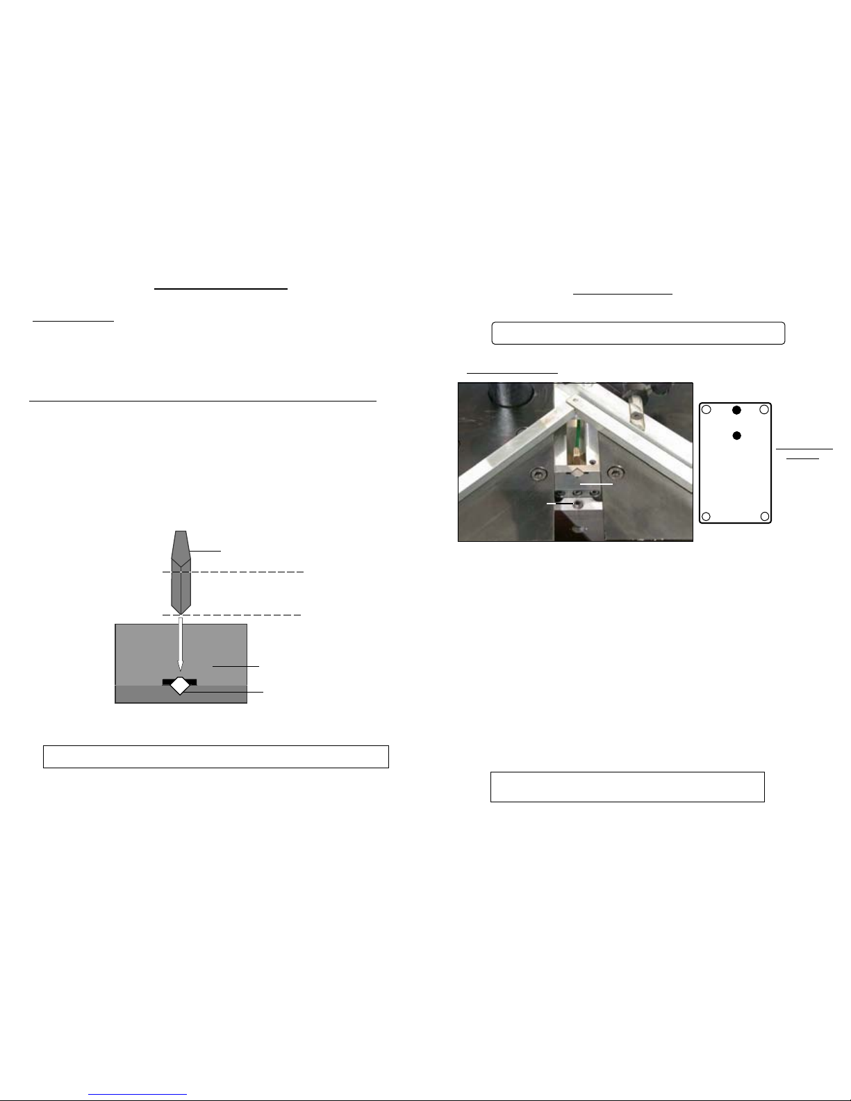
2) DEGAGEMENT D’UNE AGRAFE ENGAGEE DANS LE DISTRIBUTEUR
MAINTENANCE
En cas d’interruption du cycle d’agrafage , une agrafe peut s’engager dans le distributeur. Il est
impératif de la replacer dans le chargeur , sous peine d’enrayement :
- 2 ) Utilisez l’outil repousse agrafe (boite d’accessoires) afin de replacer l’agrafe dans le chargeur .
Le repousse agrafe ne doit pas pénétrer de plus de 6 mm à l’intérieur du distributeur .
- 3 ) Essayez de sortir le chargeur en place .Dans le cas où cela serait impossible , recommencez
l’opération 2 en respectant les 6 mm de pénétration maximum dans le distributeur .
1
) LUBRIFICATION
Périodiquement , retirez le distributeur d’agrafes (voir fig. page suivante) et sans le démonter , le
nettoyer (soufflette ) .
Il est recommandé de graisser périodiquement le marteau .Pour ce faire il faut retirer le bloc H ,
et placer une petite quantité de graisse dans le logement du marteau en bas du bloc H .
6 mm MAXIMUM
OUTIL REPOUSSE - AGRAFE
DISTRIBUTEUR
( BLOC H )
SORTIE AGRAFES
SI , APRES UN INCIDENT , L’AGRAFE N’EST PAS ENGAGEE DANS LA MOULURE ,
CELA SIGNIFIE QU’ELLE EST RESTEE DANS LE DISTRIBUTEUR ( BLOC H ) .
10
POSITION VIS
BLOC H
MAINTENANCE
3 ) DESENRAYEMENT
DISTRIBUTEUR
D’AGRAFES
( BLOC H)
- Enlevez le chargeur en place dans le couloir .
- Avec la clef hexagonale de 3 mm , dévissez la vis de blocage Vb du bloc H .
- Soulevez ensuite le bras de potence . Le distributeur d’agrafe sort de son logement .
- Le sortir complètement .
- Le marteau est resté dans le distributeur. Dévissez les 4 vis ( A , B , C , D ) et
ouvrir le bloc.
- Puis extraire le marteau cassé . Repositionnez le guide fixe , repositionnez et revissez
les 2 ou 6 vis .
- Réintroduire le distributeur d’agrafe dans son logement , fenêtre vers le chargeur .
- Graissez le marteau de remplacement . (Voir page 10 partie 1 )
- Engagez le nouveau marteau, trou vers le bas, dans le distributeur .
- Le marteau dépasse en partie , car il n’est pas dans son support .
- Enfoncez le en faisant appui dessus à l’aide d’un morceau de moulure. Tout en maintenant
le morceau de moulure en place, tirez verticalement et d’un coup sec la potence vers le haut .
- Serrez la vis de blocage Vb avec la clef hexagonale de 3 mm .
11
APRES CHAQUE INCIDENT , SI LE MARTEAU RESTE DANS LE BLOC H
VOUS DEVREZ PROCEDER A SON CHANGEMENT
A
BC
D
GF1
GF2
Vis de blocage
Vb
Si vous n’arrivez pas à enlever le sous ensemble d’agrafage,
appuyez fortement sur la potence pour décrocher le marteau.
Page 15
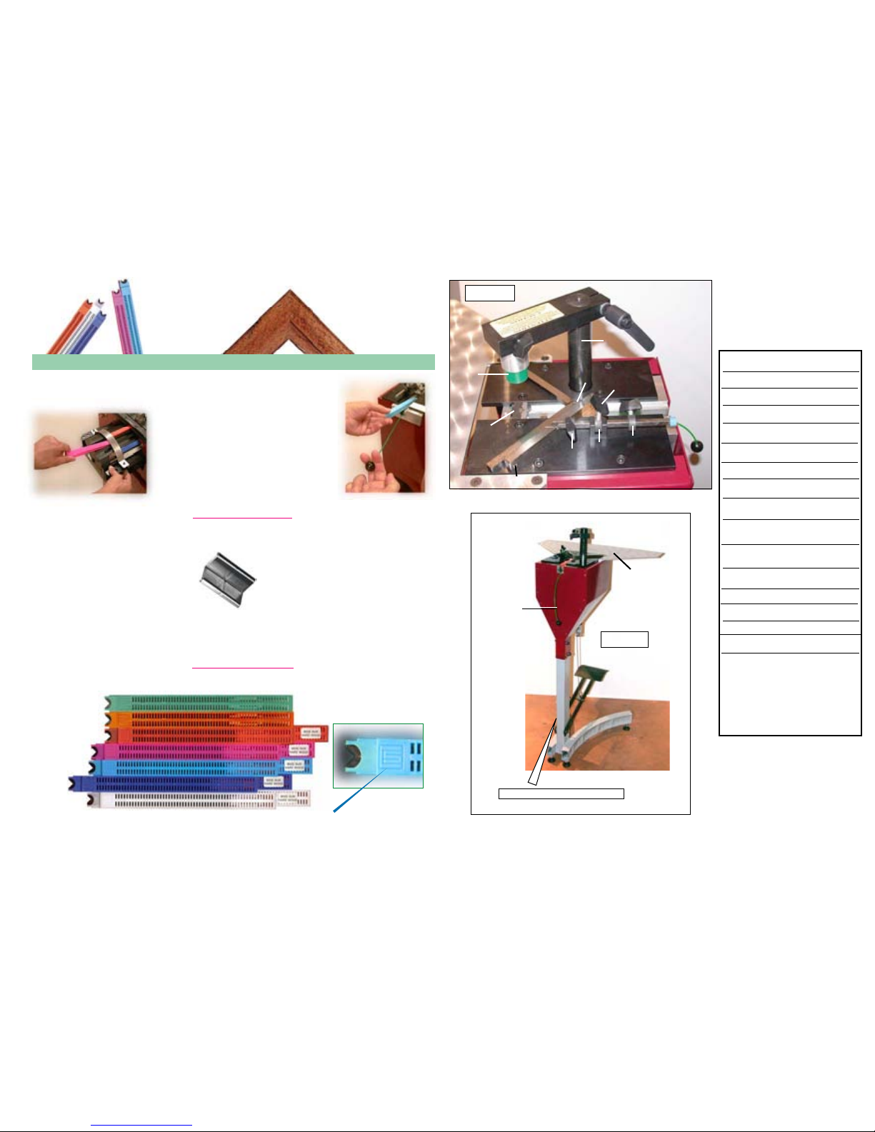
GRAPAS EN FORMA DE W
GRAPAS PARA ENSAMBLADORAS CASSESE
GRAPAS EN FORMA DE W
3 mm
Grapas CS patente cassese n° 7522814 para madera dura o blanda
Las grapas en forma de W se pueden identificar facilmente gracias al logo de cassese grabado en el cartucho.
5 mm
15
mm
12
mm
7 mm
10 mm
4 mm
Cargado del tambor de la cs 4095
Cargado de la CS 59
ensamblados de molduras, eso gracias a
su desformacion cuando entra en la madera.
Segun la densidad de la madera se puede
elegir entre grapas :
Para madera normal (7 alturas disponibles)
Para madera dura ( 5 alturas disponibles)
La grapa en w patentada por Cassese se puede usar con todas nuestras
maquinas. Su diseno especial permite un apretado perfecto de sus
FABRICACION EN ACERO DE CALIDAD SUPERIOR
GRAPAS SUELTAS SIN GOMA PARA NO ENSUCIAR A LA MAQUINA
PROTECCION ANTIOXIDACION
LUBRICADAS PARA FACILITAR LA PENETRACION EN LA MADERA
ACONDICIONADAS EN CARTUCHOS DE APROX. 275 GRAPAS
IDENTIFICACION POR ETIQUETAS DE LAS GRAPAS PARA MADERA DURA
IDENTIFICACION FACIL DEL TAMANO DE GRAPAS SEGUN EL COLOR DEL CARTUCHO
CAMBIO FACIL Y RAPIDO DEL CARTUCHO SIN GASTOS DE GRAPAS
NINGUN AJUSTE REQUERIDO PARA CAMBIOS DE TAMANO DE GRAPAS
.
EN CONFORMIDAD CON LAS NORMAS INTERNACIONALES
1
St
RESORTE DE CARTUCHO
AJUSTADO DEL ANGULO
DE ENSAMBLADO
CS 59
GRAPADORA
MECANICA
AS
B1
B2
2° TOPE
F
Po
H
P2
P1
Pr
AJUSTE TOPE
INTERIOR
DISTRIBUIDOR/ENGRAPADOR
PRENSADOR SUPERIOR
AJUSTE TOPE
EXTERIOR
MESA DE
ENSAMBLADO
P3
AJUSTE POSICION
INTERMEDIARIA
Ta
PEDAL
P
ESCUADRA DESLIZANTE
E
1° TOPE
AJUSTADOR DE TOPE
B
BRAZO PRENSADOR
AS
F
H
P1
P2
Po
Pr
B
B1
B2
E
P3
Fig N°1
Fig N°2
F
Ta
P
POSICIÓN DE REFERENCIA
Page 16
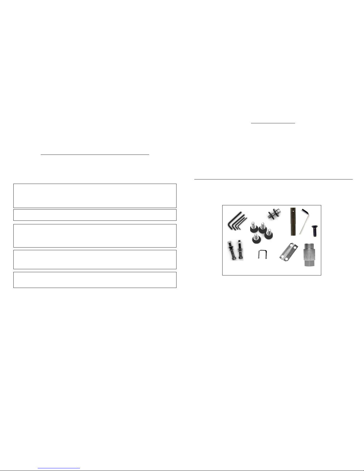
CONTENIDO PÁGINAS
INTRODUCCIÓN 2
ACCESORIOS INCLUIDOS EN LA MÁQUINA
ESPECIFICACIONES TÉCNICAS
OPCIONES
GARANTÍA
PONER EN OPERACIÓN 3, 4, 5
ENSAMBLADO
AJUSTES
SELECCIÓN DE LAS POSICIONES DE ENGRAPADO 6
INSTALACIÓN Y FIJACIÓN DE LAS POSICIONES DE ENGRAPADO 6, 7
SELECCIÓN DE PISADOR SUPERIOR 7
AJUSTE DEL ÁNGULO DE ENSAMBLADO 8
USO
MEDIDAS PARA EL ENSAMBLADO
CARGADO DEL CARTUCHO EN LA MÁQUINA 9
UNIENDO EL MARCO
MANTENIMIENTO
LUBRICACIÓN 10
COMO QUITAR UNA GRAPA ATORADA EN EL DISTRIBUIDOR DE GRAPAS 11
CS 59 - MANUAL TÉCNICO DEL USUARIO
2
Usted acaba de comprar una CS 59 ensambladora de marcos, así que lo felicitamos por su
gran decisión y le agradecemos por confiar en los productos Cassese.
Los beneficios de la CS 59 son gracias a la experiencia de las máquinas ensambladoras que le
dieron a Cassese cierta reputación. Hace posible unir molduras de madera y de plástico de
todos los tipos (N° de patente 7522814).
La CS 59 está diseñada para permitir que el operador se mueva totalmente alrededor de la
máquina.
La operación de ensamblado se puede llevar a cabo utilizando grapas de metal diseñadas para
hacer una unión sólida. Éstas grapas vienen en cartuchos de plástico, sin pegamento, lubricados
individualmente o inoxidables para las pruebas mas fuertes.
IMPORTANTE: No debe usar otros cartuchos de grapas, que no sean los manufacturados
por Cassese y marcados por Distribuidores Autorizados Cassese
(registrados con la marca CS). PREVÉNGASE DE LAS COPIAS
ACCESORIOS INCLUIDOS CON LA MÁQUINA
ESPECIFICACIONES TÉCNICAS DE LA CS 59
Ancho mínimo de la moldura : 3 mm (1/8’’) Ancho maximo de la moldura : /
Alto mínimo de la moldura : 7 mm (1/4’’). 80 mm maxi
Tamaño de las grapas en cartuchos de 275 piezas: 3, 4, 5, 7, 10, 12 y 15 mm.
Dos tipos de grapas : para maderas blandas y duras.
Peso total de la máquina : 22 kg. (47 libras)
Dimensiones : 493 mm ( ’’) x 600 mm ( ’’) (sin mesa de extensión)
x 1095 mm de altura ( ’’).
GARANTÍA
Un año de garantía para partes y mano de obra en contra de defectos de fábrica. Cualquier
parte dañada por no seguir correctamente las instrucciones de éste manual se excluyen de la
garantía.
INTRODUCCIÓN
6, 5, 4, 3 mm
x4
+ 1 Mesa de extensión + 1 Pedal +1 soporte
+ 1 Prensador cilindrico de goma altura 30 mm para madera dura
Page 17
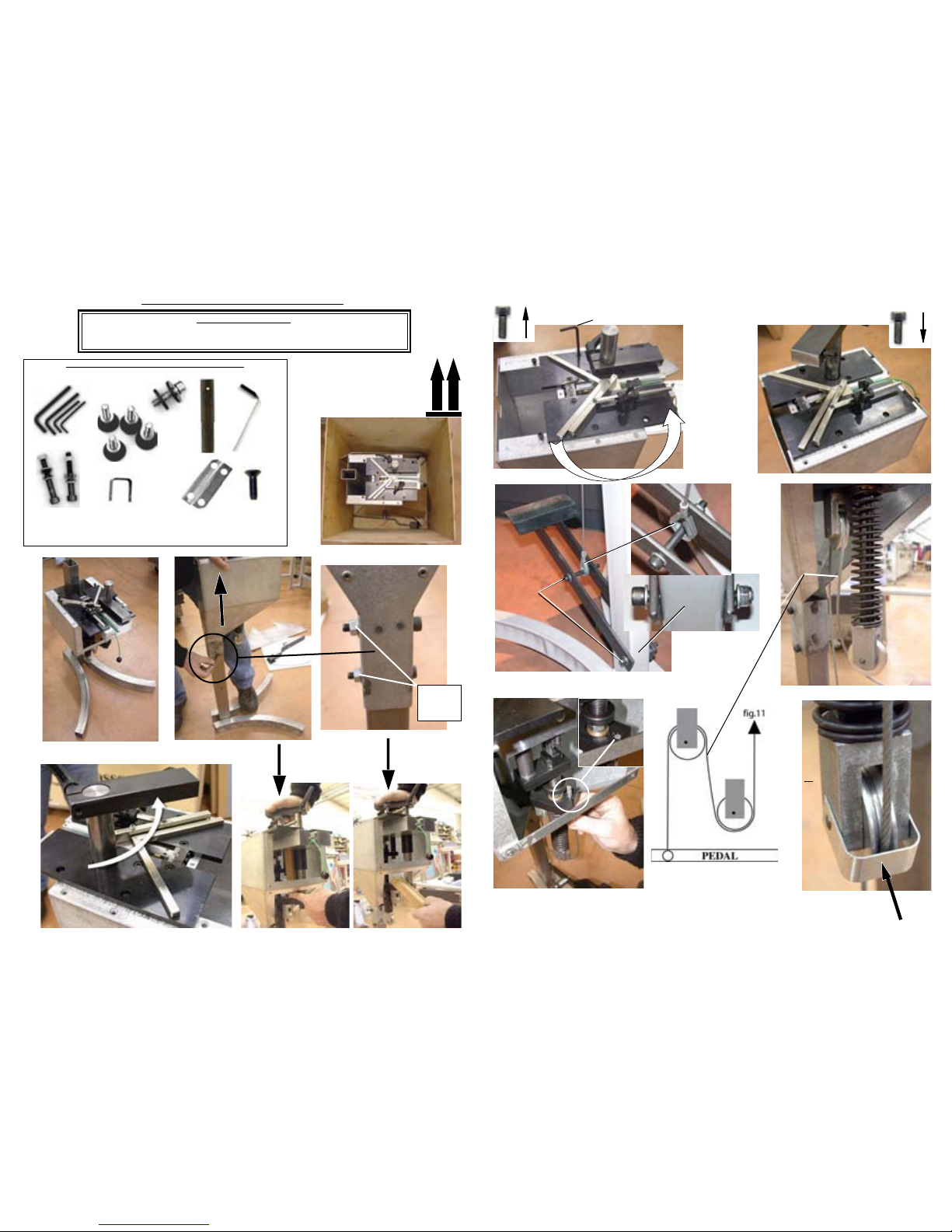
PUESTA EN MARCHA
ACCESORIOS INCLUIDOS CON LA MÁQUINA
Poner el cartón por el
suelo, de tal manera
que las flechas esten
orientadas hacia arriba
12
3
4
5
6
llave
inglesa de
13 mm
6, 5, 4, 3 mm
x4
fig. 3
pag..3
fig. 9
fig. 12
fig. 13
+ 1 Mesa de extensión + 1 Pedal +1 soporte
+ 1 Prensador cilindrico de goma altura 30 mm para madera dura
3
MUY IMPORTANTE:
QUITAR LOS 2 TORNILLOS UBICADOS BAJO LA CAJA DE MADERA
( SOSTIENEN LOS PIES DE LA MAQUINA A LA CAJA)
7
8
4 mm
10
llave
allen
6 mm
CABLE
11
10
a
b
c
d
a
b
c
d
12
x4
x4
4
Page 18
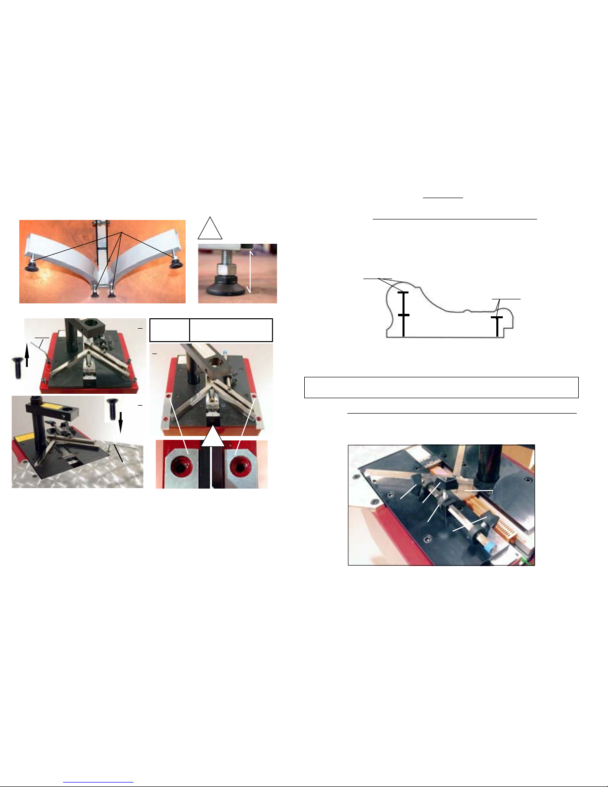
2
4 mm
x 4
1
4 mm
x 4
3
CS 59/79
Z 3585
!
-S/E TABLE
-S/A TABLE EXTENSION
-MESA DE EXTENSION
-U-GR. TISCHVERLANGERUNG
13
5
!
50 MM
MINIMO
llave inglesa de 19 mm
50 MM MINIMO
ENTRE EL
SOPORTE DE PIE Y
EL SUELO
SELECCIÓN DE LAS POSICIONES DE ENGRAPADO
La CS 59 está diseñada para unir dos o mas molduras en uno o dos lugares (posiciones)
sin límite del número de grapas en alguno de esos lugares. La selección depende del
ancho y grueso de la moldura a unir.
COMO UNA REGLA GENERAL, LA UNIÓN DEBE LLEVARSE A CABO LO MAS
CERCA POSIBLE DE LA PARTE MAS DELGADA DE LA MOLDURA.
AJUSTES
Quite los seguros de las engrapadoras. P1 , P2 et P3 .
INSTALACIÓN Y UBICACIÓN DE LAS POSICIONES DE ENGRAPADO
6
15mm
15mm
2 mm MINI-
2 mm MINI-
15 mm
Como una regla general, se permiten como mínimo 2 mm (menos de 1/8’’) por encima de las grapas.
El cambio de cartucho de las grapas del mismo tamaño se puede evitar aún cuando sean diferentes los
gruesos de las molduras.
P 1
P2
P3
B1
Escuadra
Deslizante
B
Page 19
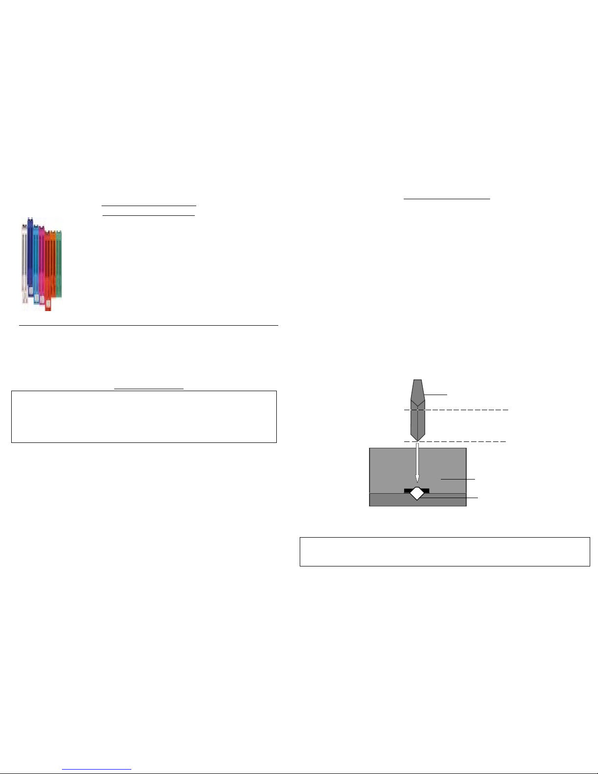
9
Las posiciones de engrapado son seleccionadas ( ver memorisacion de las posiciones de
engrapado pagina 6 y 7)
Ver ajuste del angulo del ensamblado (ver pagina 8)
La distancia entre la moldura y el prensador no supera los 30 mm
Seleccion del prensador (ver pagina 8)
Se cargo el tamano correcto de grapas (para madera dura o normal)
Después de escoger y seleccionar las posiciones de engrapado, ajuste el ángulo de ensamblado,
revisando la distancia entre el pisador superior y la moldura, y prepare el tamaño de grapas
adecuado.
1) Ponga la primera moldura frente de la barra B1 y empújela de tal manera que el final alcance la
otra barra B2.
2) Sosteniéndola, ponga el segundo corte de la moldura en contra de la barra B2 y deslícelo hasta
que alcance la primera moldura.
3) sosteniendo las molduras, una en contra de la otra, sostenga las barra B1 y B2 con sus pulgares
y haga que el ángulo de ensamblaje se deslice hasta que la palanca P1 alcance el límite de B.
4) Aún sosteniendo las molduras, pise el pedal P. Si desea poner mas grapas en la misma posición
tire del pedal nuevamente.
5) si hay una nueva posición de engrapado escogida, rep
ita la misma operación presionando las
molduras hacia el ángulo de ensamblado hasta que P2 alcance el límite de B, y repita el paso 4.
UNIENDO EL MARCO
Tire del cordón con la bola del pisa grapas totalmente.
Si hay algún cartucho dentro de la máquina, sosteniendo el cordón, sáquelo solamente
deslizándolo.
Sosteniendo el cordón, ponga un nuevo cartucho de grapas y asegúrese de que esté bien colocado
en el distribuidor de grapas.
Acomode el cordón nuevamente cuidadosamente.
USO CORRECTO DE GRAPAS
La unión se lleva a cabo usando grapas metálicas, un invento de Cassese,
diseñado para tener solidas esquinas. Hay cinco medidas disponibles:
3,4,5,7,10,12 y 15 mm, se encuentran en cartuchos desechables, en diferentes
colores para identificarlos por su tamaño. Las grapas con cargador las hay en
dos versiones: NORMALES, para maderas suaves y normales, y las grapas
HW para maderas muy duras. Éstas grapas para madera dura sólo son para
usarse en maderas duras. Su máquina CS 59 está diseñada para usar todos los
tamaños de cartuchos Cassese sin cambiar ninguna parte de la máquina o
ajustar algo.
Para un mejor y mas prolongado uso de su Cassese, asegúrese de comprar
cartuchos originales.
INSTALACIÓN Y CAMBIO DE LOS CARTUCHOS DE GRAPAS EN SU MÁQUINA
ENSAMBLANDO
MANTENIMIENTO
1) LUBRICACIÓN
Remueva periódicamente el distribuidor de grapas, y límpielo con una pistola de aire
sin desmontarlo.
Es recomendable lubricar el martillo periódicamente. Para hacer eso, quite el distribuidor
de grapas y ponga una pequeña cantidad de grasa en el botón del distribuidor de grasa.
El martillo estará lubricándose cada vez que pase por el distribuidor de grapas.
2) COMO QUITAR UNA GRAPA ATORADA DEL DISTRIBUIDOR DE GRAPAS
Si usted pisa el pedal a medias y lo suelta, una grapa puede quedar atorada en el distribuidor de
grapas. Si esto llega a suceder:
- Cierre la válvula de aire.
- Trate de remover el cartucho que se encuentra en posición, si se resiste, use la herramienta
quita grapas para empujar la grapa de vuelta en el cartucho.
Asegúrese de no meter la herramienta mas de 6 mm (1/4’’) dentro del d
istribuidor de grapas.
6mm MAXIMO
HERRAMIEMTA
DISTRIBUIDOR
( BLOC H )
SALIDAS GRAPAS
Es muy importante que no deje una grapa atorada en el distribuidor de grapas, ya que
puede causar la inserción de dos grapas cuando usted tenga que unir la siguiente esquina,
o puede atascar el martillo en el distribuidor de grapas.
10
Page 20
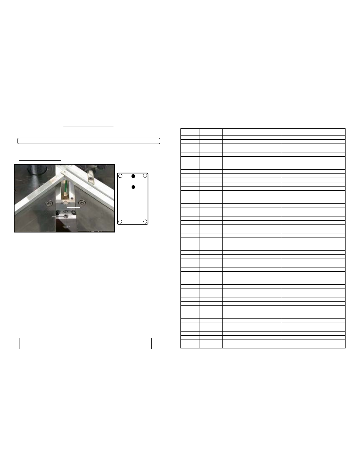
POSICION
TORNILLOS H
MANTENIMIENTO
3 ) DESENBLOQUEADO
DISTRIBUIDOR/
CABEZAL DE
GRAPAS H
En caso de que el martillo se atasque en el distribuidor de grapas:
- Quite el cartucho.
- Utilizando la llave Allen de 3 mm afloje el tornillo del distribuidor de grapas.
- Levantar el pisador superior parte por parte, el distribuidor de grapas saldrá de su
ubicación.
- Sepárelo de la máquina.
- Si el viejo martillo está atorado en el distribuidor de grapas: primero trate de quitarlo con
un par de alicates. Si no es posible, quite los 4 tornillos (A, B, C, D) . Para esto use la llave
Allen mas pequeña, que es de 2.5 mm. Despues se puede abrir el distribuidor y libere
totalmente el martillo viejo. Si no es posible quitar el martillo viejo, qu
ite los cuatro
tornillos, y abra nuevamente.
- Quite el martillo viejo.
- Volver a colocar el distributor de grapas en su ubicacion. Apertura hacia el cartucho
- Poner grasa sobre el nuevo martillo.
- Colocar el nuevo martillo en el distribuidor de grapas, agujero hacia abajo (el martillo
sobrepasa ya que no esta en su ubicacion todavia).
- Poner una moldura sobre el martillo, y mainteniendola, levantar el pisador de un golpe.
- Atornillar el tornillo VB.
- Su máquina está lista para trabajar nuevamente.
11
SI EL MARTILLO QUEDA BLOQUEADO EN EL CABEZAL , CAMBIELO
A
BC
D
GF1
GF2
TORNILLO DE
BLOQUEADO VB
SI USTED NO LOGRA SACAR EL CABEZAL DE ENGRAPADO , APRETE
FUERTE EL PRENSADOR PO PARA DESENGANCHAR EL MARTILLO
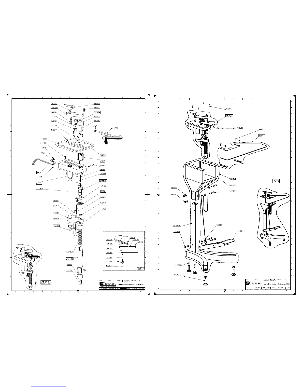
Quantité CODE_Z DESIGNATION D ESIGNATION
1 Z1067 Entretoise Spacer
1 Z1068 Butée Fixe Fixed stop
1 Z1069 Guide Butée B ackstop guide
1 Z1086 Butée Mobile Stop
1 Z1311 Vis STF M6-10 Nylon Screw STF 6 x 10
1 Z13290 Potence Plunger Arm
1 Z1338 Ecrou H M12 N ut H M12
1 Z13453 RESSORT Spring
1 Z13808 Colonne Column
1 Z13809 S/E Support marteau Hammer support Sub/Assembly
1 Z1412 Ecrou Nylstop M4 Nut M4
2 Z1580 Rondelle Z10 Washer Z10
1 Z1612 Rondelle M8 Washer M8
1 Z1719 Goupille cylindrique 3x12 Pin 3 x 12
1 Z1720 Goupille cylindrique 3x20 Pin 3 x 20
2 Z1751 Goupille élastique 4x20 Pin 4 x 20
4 Z1779 Bouton M6-10 B utton M6 x 10
1 Z1820 Manette indexable M8 x 50 Adjustable handle
1 Z275 Vis CHC M10-30 Screw CHC 10 x 30
1 Z279 Vis CHC M10-80 - 8.8 Screw CHC 10 x 80
1 Z288 Vis CHC M3-10 Screw CHC 3 x 10
1 Z309 Vis CHC M4-60 Screw CHC 4 x 60
6 Z330 vis CHC M6-12 Screw CHC 6 x 12
1 Z3557 Tôle ressort anti saute cable Sheet metal for cable
1 Z3558 Plaque de butée Backstop holder plate
1 Z3559 Plaque de potence Plunger Arm plate
1 Z3561 Support Support
1 Z3567 Chape de tige hexagonale de 8 Cap
1 Z3568 tige hexagonale de 8 Hexagonal axe
1 Z3569 Contre Butée Stop support
3 Z3570 Butée de profondeur Adjustable stop
1 Z3577 S/E Equerre coulissante Sliding square
1 Z3581 S/E Plaques plates Sub/Assembly
1 Z13422 S/E CHAPE ET AXE Cap and axel
1 Z3591 S/E Embase équipée Base assy
1 Z4569 S/E Chape et goupille Cap and pin
1 Z4624 Butoir stop
1 Z506 Marteau Hammer
1 Z6069 Butée basse Bottom stop
2 Z650 Vis FHC M4-10 Screw FHC 4 x 10
1 Z653 Vis FHC M4-25 Screw FHC 4 x 25
1 Z764 Palier Bearing
1 Z770 Coulisseau Wedge pusher
2 Z788 Poulie Pulley
1 Z811 S/E Tambour Assy wedge pusher spring
1 Z817 S/E Agrafage + Guide Wedge distributor with square guide
1 Z826 S/E Fil Ø 2.5 A ssy wire + ball
1 Z8348 Vis CHC M16-30 Screw CHC 16 x 30
1 Z900 Ecrou réglage butée d'agrafage Wedge insertion stop nut
1 Z4559 S/E Support élastomère vert Ø30mm
CS 59 - LISTE DES PIECES DETACHEES - SHEDULE OF SPARE PARTS
Page 21
Page 22
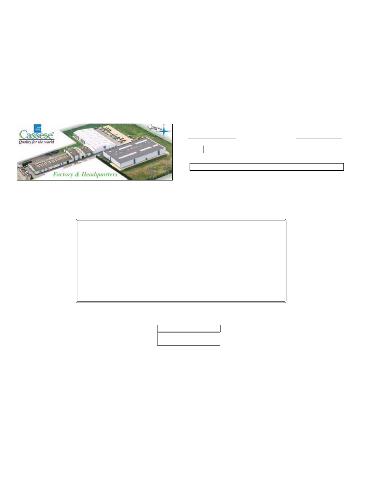
Zone Industrielle
F - 77390 VERNEUIL L’ETANG - FRANCE
Tel: 01 - 64 - 42 - 49 - 50 / Fax: 01 - 64 - 42 - 58 - 90
E-mail : [email protected]
Tel : 33 - 1- 64 - 42 - 49 - 71 Fax : 33 - 1- 64 - 06 - 04 - 19
33 - 1- 64 - 42 - 49 - 72 33 - 1- 64 - 49 - 58 - 94
WebSite : www.cassese.com E-mail : [email protected]
INT’AL SALES
SERVICE APRES VENTE / AFTER SALES DEPARTMENT /
KUNDENDIENST DIENST / SERVICIO TÉCNICO:
(33)-01-64-06-24-51
http://www.cassese.com
 Loading...