

Cassese CS1 CART User Manual
FOOT OPERATED UNDERPINNER
Inventor and World No.1 Manufacturer of
Picture Framing Machines & Consumables Since 1976
CS1 CART
USER & PARTS MANUAL
Version 2 11/ 2014
Cassese® / Communication
Z26059
READ THIS MANUAL CAREFULLY
BEFORE USING THE MACHINE
Non contractual document - Cassese France® - Document non contractuel
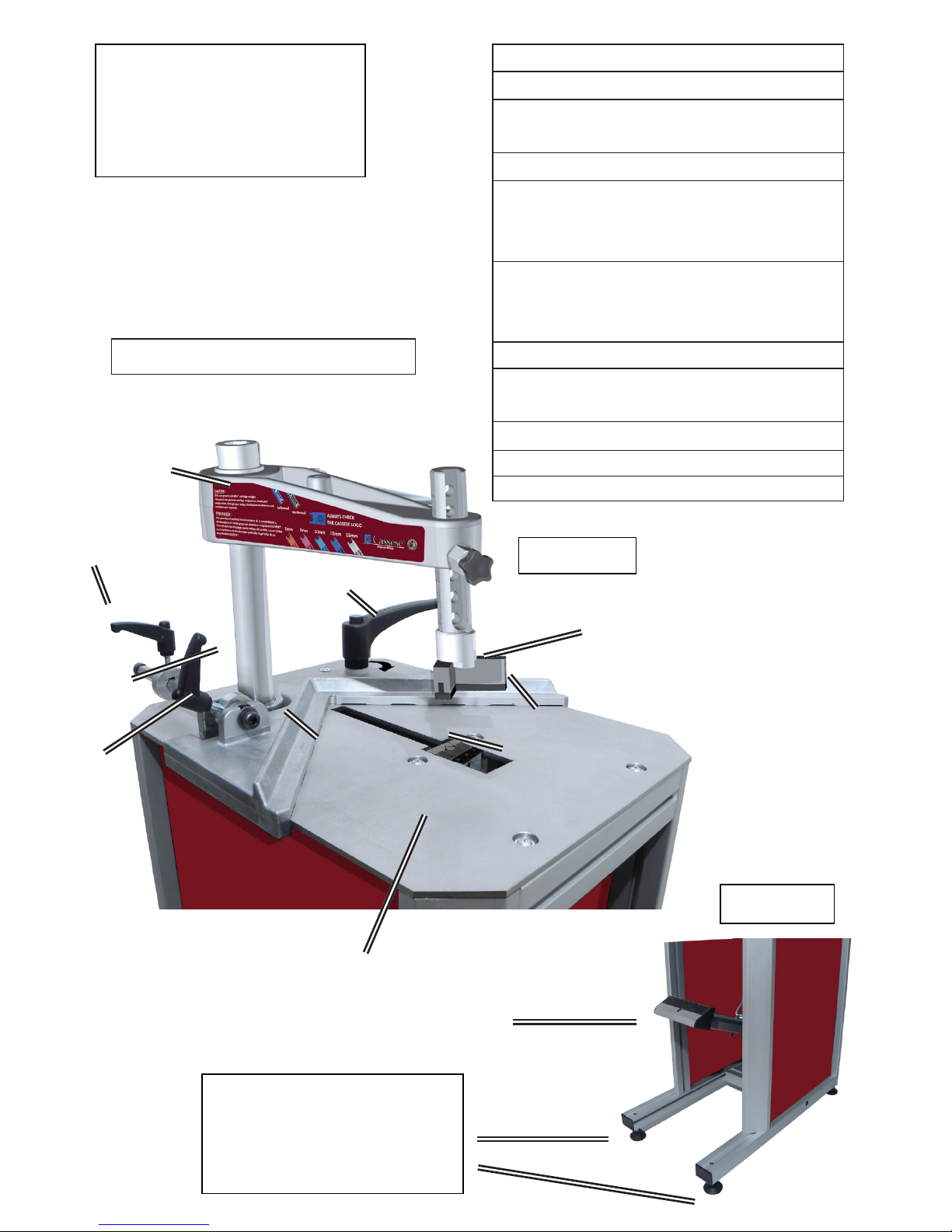
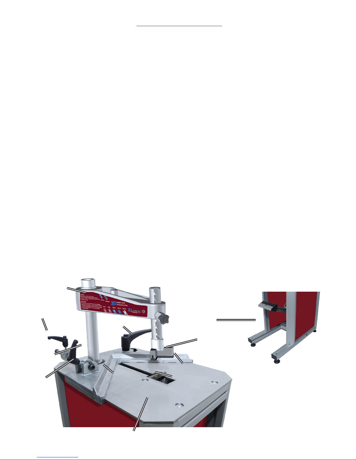
CS1 CART
FOOT OPERATED
UNDERPINNER
1st BACK FENCE 1
2nd BACK FENCE 2
HANDLE FOR LOADING
WEDGES 3
WEDGE DISTRIBUTOR BLOCK 4
WEDGE POSITION
STOP HANDLE
(inside of frame) 5
WEDGE POSITION
STOP HANDLE
(outside of frame) 6
PEDAL 7
MAGNETIC ADJUSTABLE
ROD CLAMP ASSEMBLY 8
CROSSBAR 9
STAPLING STOP 10
TABLE 11
WORK POSITION REFERENCE
9
6
5
10
2
1
8
3
4
11
7
Fig N°1
Fig N°2
AFTER UNPACKING THE
MACHINE, SET THE 4 FEET
TO LEVEL THE MACHINE

Non contractual document - Cassese France® - Document non contractuel
INTRODUCTION 2
ACCESSORIES SUPPLIED WITH THE MACHINE
TECHNICAL SPECIFICATIONS OF CS1 CART
OPTIONS
GUARANTEE
ADJUSTMENTS
SELECTION OF WEDGE POSITIONS 3
SETTING AND STORING THE WEDGE POSITIONS 3, 4
PROPER ADJUSTMENT OF MAGNETIC ADJUSTABLE 5
ROD CLAMP ASSEMBLY
USE
MEANS OF JOINING 6
LOADING CARTRIDGE WEDGES 6
CHANGING WEDGES SIZE 6
JOINING THE FRAME 7
MAINTENANCE
A) DISMANTLING THE WEDGE DISTRIBUTOR BLOCK 9
B) CLEANING AND LUBRICATION OF THE WEDGE DISTRIBUTOR BLOCK 10
C) REMOVAL OF THE WEDGE DRIVER BLADE 11
D) INSTALLATION OF NEW WEDGE DRIVER BLADE 12
E) UNJAMMING OF THE WEDGE DISTRIBUTOR BLOCK 13
F) REMOVING THE SIDE PANEL 14
G) REMOVING THE WORKING TABLE WITH THE PEDAL 14
H) REPLACEMENT OF THE WEDGE DISTRIBUTION CHANNEL
ELASTIC CORD 15
CS1 CART - USER & PARTS MANUAL
CONTENTS Page
1
Non contractual document - Cassese France® - Document non contractuel
CS1 CART - USER & PARTS MANUAL
INTRODUCTION
Thanks for having purchased the CS1 CART underpinner and for your trust in Cassese
products. The CS1 CART benets from Cassese’s experience since 1976 in designing and
manufacturing highest quality underpinners, for which we are world-famous. The CS1
CART will allow you to join wooden, plastic and MDF proles (patent n° 7522814). Joining
operation is carried out by using Genuine Cassese® Cartridge Wedges, specially designed
to perform perfect and tight frame corners.
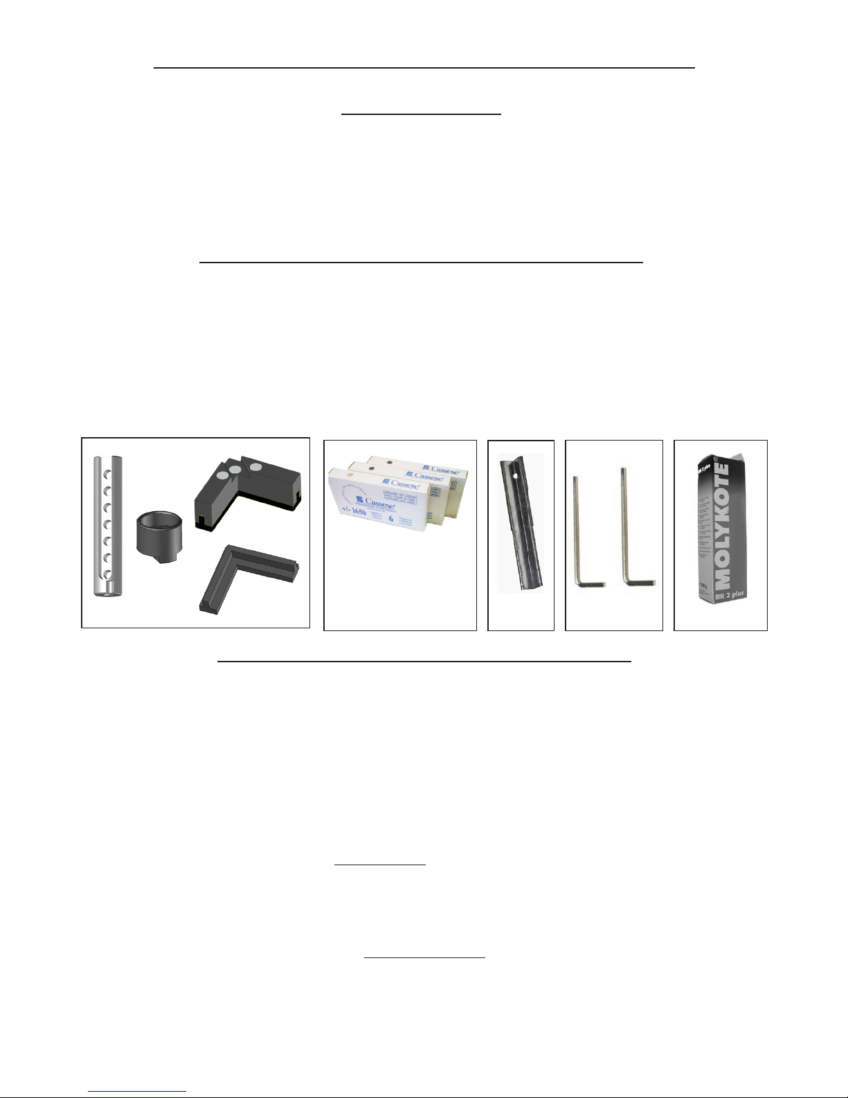
ACCESSORIES SUPPLIED WITH THE MACHINE
A) 1 Magnetic adjustable rod clamp + 1 Chevron holder + 1 Magnetic chevron clamp + 1
Chevron rubber.
B) 1 box of 7mm Softwood + 1 box of 10mm Hardwood + 1 box of 10mm Softwood.
C) 1 Wedge driver blade for using CASSESE® Genuine Cartridge Wedges.
D) 1 Allen Key 2.5 mm + 1 Allen Key 3 mm.
E) 1 Grease Tube.
TECHNICAL SPECIFICATIONS OF CS1 CART
Minimum moulding width: 5mm (1/4”) / Minimum moulding height : 7 mm (11/16”)
Maximum moulding width: ∞ mm / Maximum moulding height : 85 mm ( 3 11/32” )
Maximum stroke between rst and last wedge (at 45°) : 140 mm (5 1/2”)
CASSESE® Genuine Cartridge Wedges sizes: 5, 7, 10, 12 and 15 mm.
3 wedge types : Softwood, Hardwood & MDF. Use only CASSESE® Genuine cartridge
wedges.
Machine gross weight : 23 kg (51 lbs) - Dimensions : Width 360mm (14’’) x Depth (w/
out extension table) 610mm (23’’
3/4
) x Height 1200 mm (47’’).
OPTIONS (page 24)
- Z1791 Green round clamp - Z1783 Yellow round clamp - Z25510 Stainless steel
table extension - Z25147 Stainless steel shelf for wedges and accessories - Z25450
Extension arms -
GUARANTEE
One year guarantee for parts and labour against manufacturing defects. Wear
parts and those damaged as a result of non compliance with the instructions of the
present manual are excluded from the guarantee. Loading spring and wedge driver
blade are considered as wear parts.
2
A B
C
D
E
Z1879
Z506
Z1896Z1882
Z21525
Z21524
1 box of 7mm SW
+
1 box of 10mm HW
+
1 box of 10mm SW
Z24703
Z26999
Non contractual document - Cassese France® - Document non contractuel
3
ADJUSTMENTS
SELECTION OF WEDGE POSITIONS
The CS1 CART is designed to join mouldings in one, two or more positions without
limitation of the number of wedges in any of those places. The selection depends
on the width and height of the moulding to join.
As a general rule, a MINIMUM 2 mm clearance (less than 1/8”) above the wedges
shall be respected.
Same size wedges can be stacked in order to avoid changing the size of wedge
when joining tall mouldings.
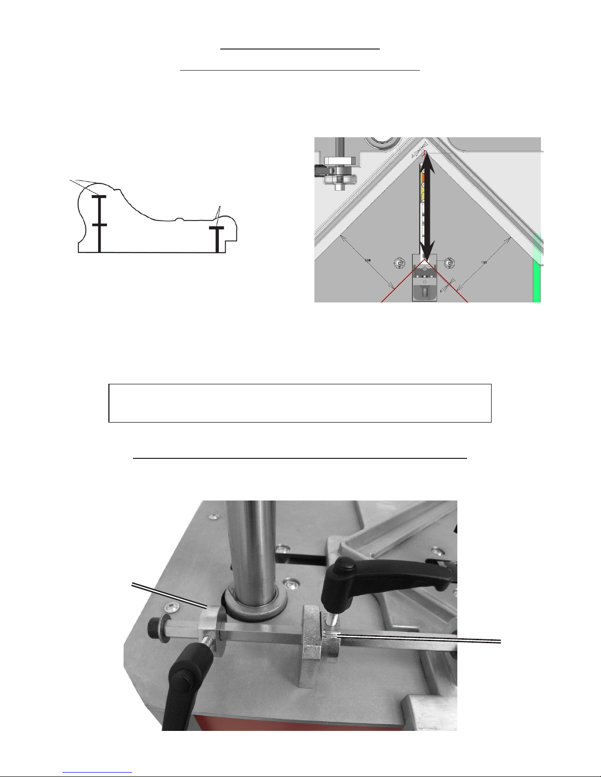
AS A GENERAL RULE, THE WEDGE POSITIONS MUST BE SELECTED
VERTICALLY TO THE HIGHEST POINTS OF THE MOULDINGS.
SETTING AND STORING THE WEDGE POSITIONS
Unlock the wedge position stop handles 5 and 6.
140mm
stroke
2mm MINIMUM
2mm MINIMUM
6
5
Non contractual document - Cassese France® - Document non contractuel
4
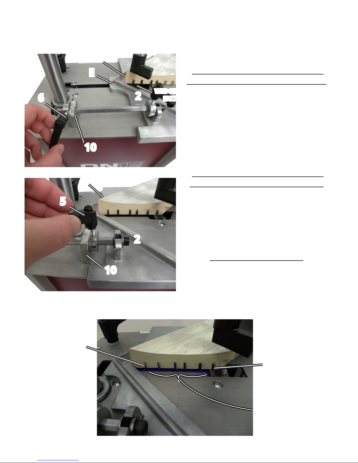
Put the rst moulding in front of the back fence 1 and slide the moulding in
contact with the 2nd back fence 2.
Setting up the stapling position
close to the outside of the frame :
Move forward the sliding table E until the
place where you want to insert the wedge(s)
has been reached by the WEDGE EXIT (see
picture). Then bring the wedge position
stop handle 6 against the stapling stop 10
and tighten it.
Setting up the stapling position
close to the inside of the frame :
Move backwards the sliding table E until
you have reached the furthest position to
the inside of the frame where you want to
insert wedge(s).
Then bring the wedge position stop handle
5 against the stapling stop 10 and tighten it.
Now the two positions of joining are
set and the sliding table can move only
within the limits of these two positions.
WEDGE
EXIT
E
10
6
10
5
Wedges between
the rst and the
last position
1st position
Last
position
2
1
2
1
Non contractual document - Cassese France® - Document non contractuel
5
PROPER ADJUSTMENT OF MAGNETIC ADJUSTABLE
ROD CLAMP ASSEMBLY
A magnetic adjustable rod
clamp comes with your
machine as a standard
feature. It ts the crossbar
thanks to the locking ring
pin and can be set at 1 to 7
positions.
You must have 30mm (1 1/4”)
max between the clamp and
the mouldings.
It helps to avoid any mistakes in
the joining of the frame.
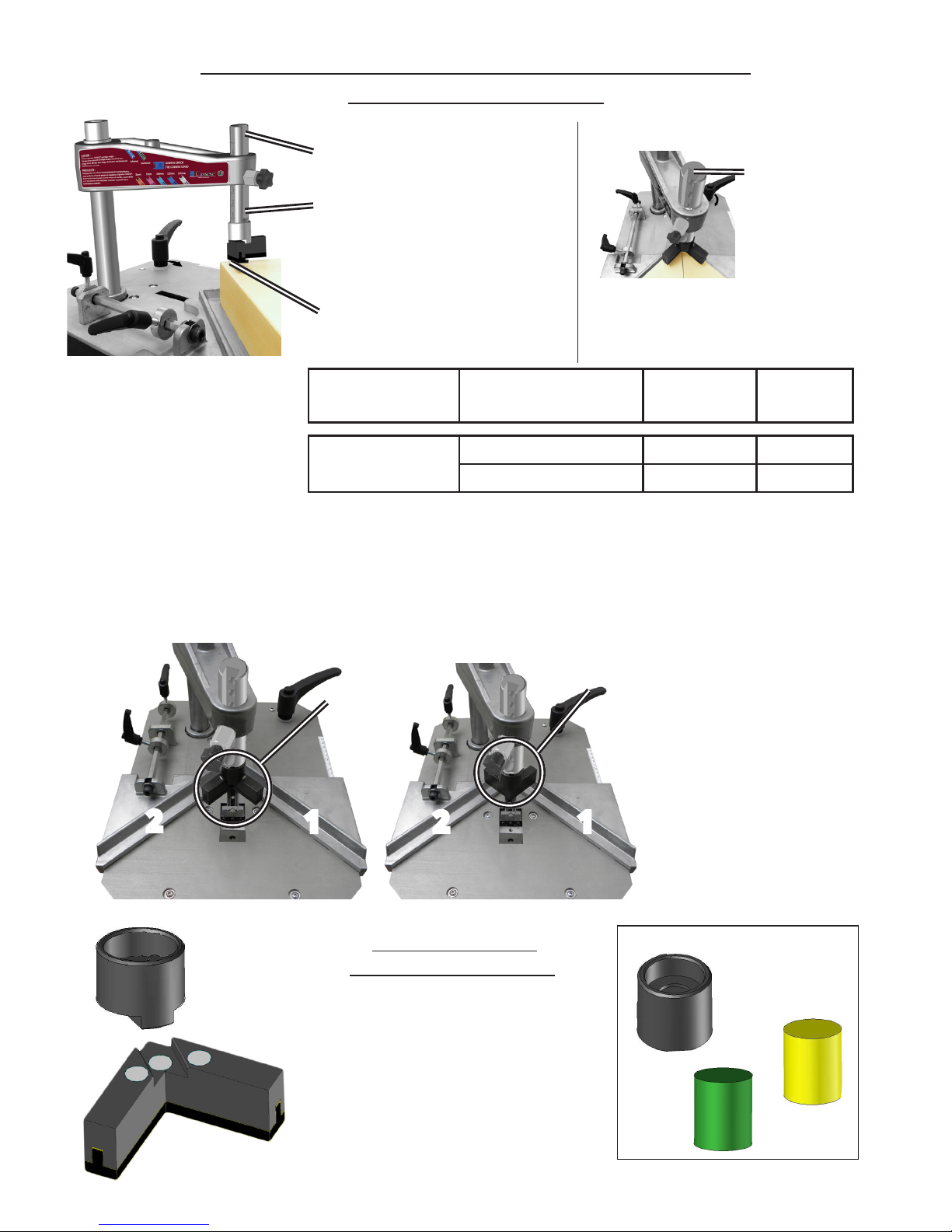
ACCESSORIES SUPPLIED WITH THE MACHINE: Magnetic chevron clamp is ideal for at
mouldings or for hard to reach surfaces.
OPTIONS: The round clamps are dedicated to complicated forms and sloped mouldings.
NEW MAGNETIC
ADJUSTABLE CLAMPS
Now with quick-change magnetic
clamps, it is easy to change from
chevron to a round clamp.
Accessories supplied
with the machine
Magnetic Chevron Clamp
HARDWOOD &
SOFTWOOD
ONE SIZE
Z21525
Z18065
Z1783
Z1791
OPTIONAL
Z24703
GOOD
BAD
Pay attention to properly
position the magnetic
chevron clamp : the sides of
the chevron must be parallel
to back fences 1 and 2.
Options
Green Round Clamp HARDWOOD 30 & 45mm
Yellow Round Clamp SOFTWOOD 30 & 45mm
Always have
the notch
(mark) turned
to the front of
the machine.
2
1 2 1
Non contractual document - Cassese France® - Document non contractuel
6
USE
Boxes of 40
cartridges (app.
275 wedges)
=
11.000 wedges/
box
Boxes of 6
cartridges (app.
275 wedges)
=
1.650 wedges/
box
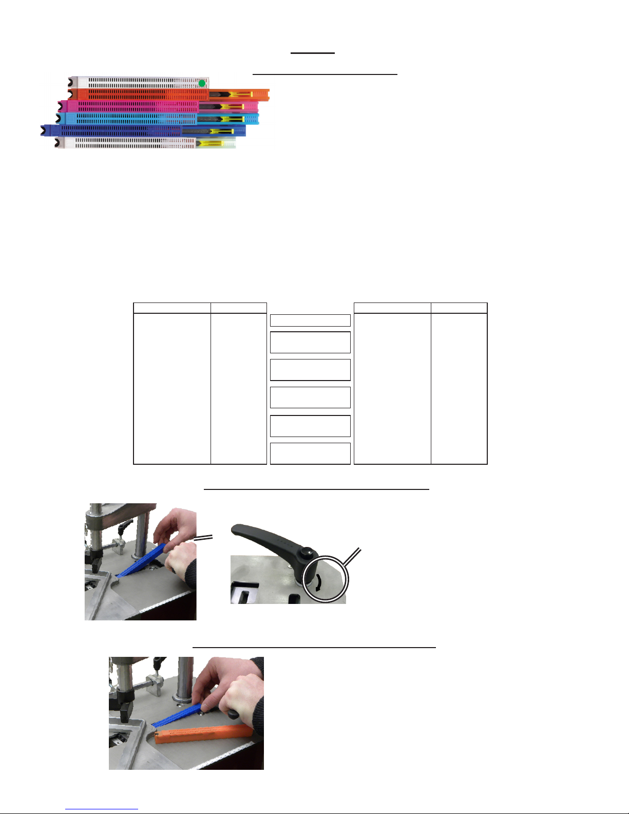
MEANS OF JOINING
Joining is performed by using metal wedges, a Cassese
invention, specially designed to ensure perfect
corners.
Six standard sizes are available : 3, 5, 7, 10, 12 and
15mm.
They come in eco-friendly cartridges, thanks to a recyclable plastic, that are color-coded per size
for easy identication. Cartridge wedges exist in 3 versions: NORMAL for SOFTWOOD (identiable
by their white plastic pusher), HW for HARDWOOD (identiable by their yellow plastic pusher)
and MDF (identiable by their red plastic pusher or red sticker on individual boxes).
Your CS1 CART underpinner is designed for using all sizes of CASSESE® Genuine Cartridge Wedges
without having to change any parts on the machine or having to adjust anything.
For the best corner join, reliability and performance, use only CASSESE® Genuine Cartridge
Wedges.
WHITE
REFERENCE
30303NCOI
30305NCOI
31305BDCO
30307NCOI
31307BDCO
30310NCOI
31310BDCO
30312NCOI
31312BDCO
30315NCOI
31315BDCO
TYPE
3mm
5mm
5mm HW
7mm
7mm HW
10mm
10mm HW
12mm
12mm HW
15mm
15mm HW
TYPE
3mm
5mm
5mm HW
7mm
7mm HW
10mm
10mm HW
12mm
12mm HW
15mm
15mm HW
REFERENCE
30403NCOI
30405NCOI
31405BDCO
30407NCOI
31407BDCO
30410NCOI
31410BDCO
30412NCOI
31412BDCO
30415NCOI
31415BDCO
ORANGE
PINK
LIGHT BLUE
DARK BLUE
WHITE
LOADING CARTRIDGE WEDGES
CHANGING THE SIZE OF WEDGES
Repeat the procedure of loading cartridge
wedges but remove the cartridge.
Then insert the new size of cartridge wedges.
Then release the handle for wedges’ loading 3.
Turn handle for loading wedges 3 in
direction of arrow in order to bring
back cartridge wedges pusher.
While holding handle in this position,
insert cartridge into cartridge channel.
Then gently release the handle for
loading wedges 3.
3
Non contractual document - Cassese France® - Document non contractuel
JOINING THE FRAME
After selecting and setting the wedge positions (page 4 & 5), check the distance
between the clamp and the moulding (page 6). Load the required type (softwood,
hardwood or MDF) and size of wedges (page 4).
1
st
step : Put the rst moulding in front of the back fence 1 and push it so that its
mitre end reaches the other back fence 2.
2
nd
step : Holding it so, put the second moulding against back fence 2 and slide it
until it reaches the rst moulding.
3
rd
step : Holding the mouldings in place against each other, hold the back fences 1
& 2 with your thumbs. Move the sliding table E backwards until the wedge position
stop handle 5 reaches the stapling stop 10.
4
th
step : Keeping the mouldings secure, slowly push down the pedal 7.
When the the magnetic adjustable rod clamp assembly 8 will press down on the
mouldings, speed up the movement so that the wedge is inserted more easily.
5th step : If there is a second wedge position (with wedge position stop handle 6),
just repeat the same operation by moving forward the mouldings and the sliding
table E until wedge position stop handle 6 reaches the stapling stop 10 and repeat
step 4.
NOTE* : If stapling more than one wedge in any position is desired then repeat 4th
step.
7
9
6
5
10
2
1
8
3
4
11
7
Non contractual document - Cassese France® - Document non contractuel
8
CAUTION! To ensure your safety, it is imperative to disconnect the air supply coupler before
any intervention on the mechanical and pneumatic components of the machine.
MAINTENANCE
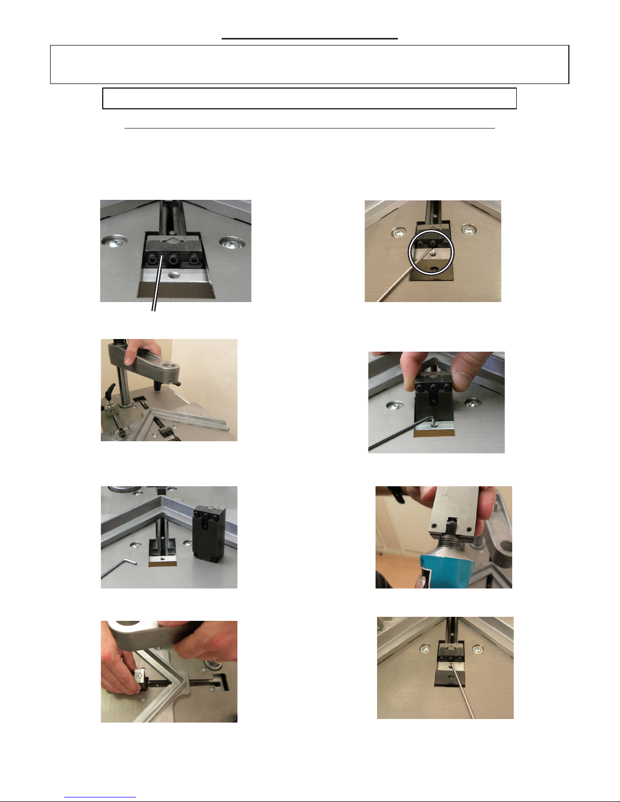
A) DISMANTLING THE WEDGE DISTRIBUTOR BLOCK
WEDGE DISTRIBUTOR BLOCK
Periodically, remove the wedge distributor block and clean it with an air gun.
It is recommended to lubricate the wedge driver blade (use the Cassese’s grease Z1896).
To do so, you will have to remove the wedge distributor block with the 2,5mm Allen Key and
perform this procedure. First, remove the cartridge of wedges from the underpinner.
CAUTION: WHEN USING COMPRESSED AIR, WEAR SAFETY GLASSES.
Unlock half a turn the locking screw of the
wedge distribution block with the 2.5mm Allen
key that is supplied with the machine.
Pull up the wedge
distributor block.
Remove the wedge distributor
block from the machine.
Pull up the crossbar in order to move
the wedge distributor block out of its
place.
1. 2.
3.
4.
5.
Pull up the crossbar in order to insert the
wedge distributor block on the wedge
driver blade with the window in direction
of the cartridge of wedges.
Apply a small amount of grease at the
bottom of the wedge distributor block.
Tighten the locking screw of the wedge
distributor block, paying attention to
level it with the working table.
7.
6.
8.
Non contractual document - Cassese France® - Document non contractuel
9
To clean up the wedge distributor block in order to avoid any stapling problem,
follow steps 1 to 5 of instructions of A) (ref. page 9), then proceed with step 1 :
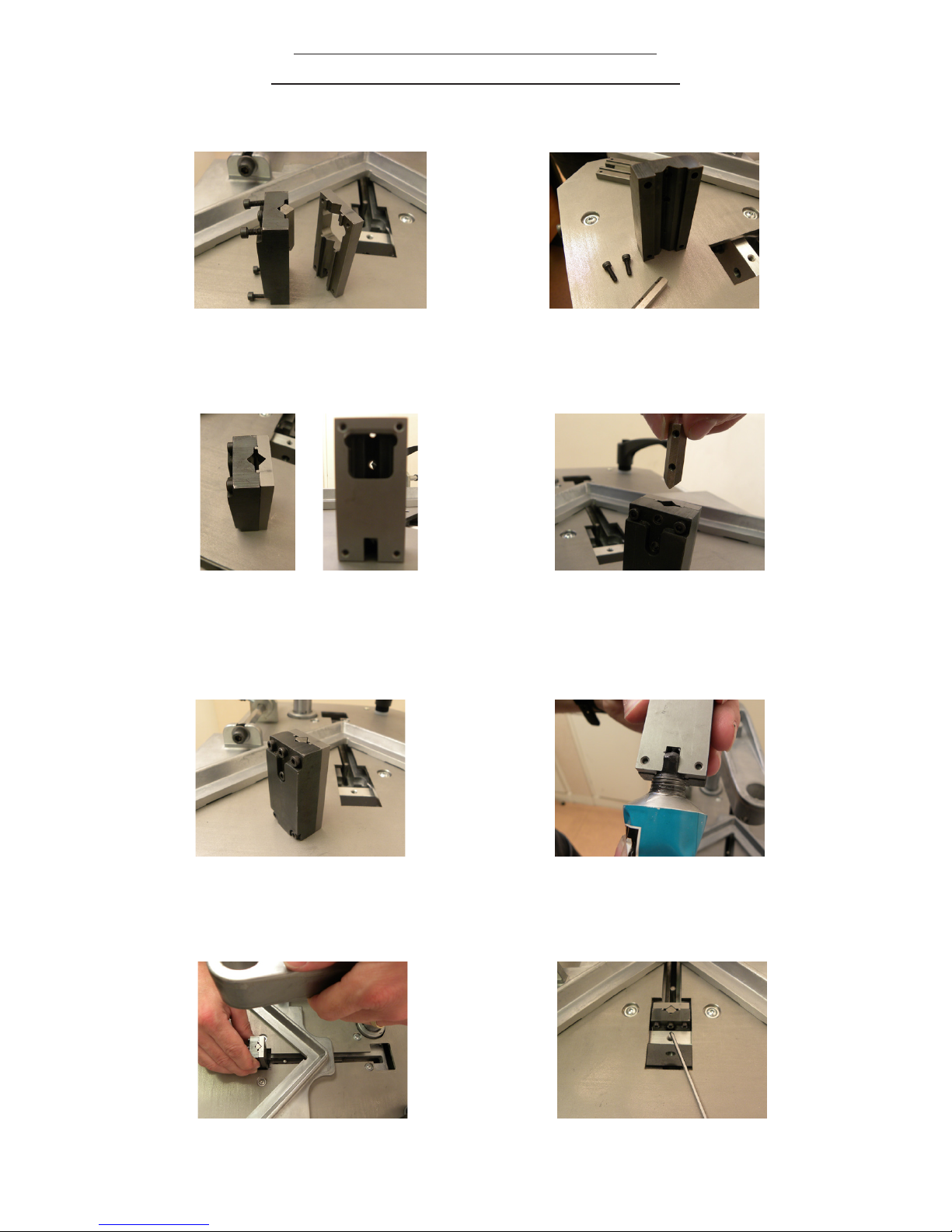
B) CLEANING AND LUBRICATION
OF THE WEDGE DISTRIBUTOR BLOCK
Unlock the two remaining screws to
remove the center post of the wedge
distributor block. Caution! : These are
the smallest screws of the block.
Unlock the four corner screws of
the wedge distributor block with the
2.5mm Allen key supplied with the
machine. Separate the two pieces.
Insert the last piece as shown in
the picture.
Before tightening the screws, check the
level of the pieces on the top of the wedge
distributor block in order to have a perfect
reassembly as shown in the picture.
Pull up the crossbar in order to insert the
wedge distributor block on the wedge
driver blade with the window facing the
cartridge channel.
After having cleaned up the wedge distributor
block, assemble these both pieces rst. Pay
attention to level them on the top before
tightening the screws. The window must be
facing to the both screws’ holes.
Apply a small amount of
grease at the bottom of the
wedge distributor block.
Tighten the locking screw of the wedge
distributor block, paying attention to
level it with the working table.
1. 2.
3. 4.
5.
7.
6.
8.
Non contractual document - Cassese France® - Document non contractuel
C) REMOVAL OF THE WEDGE DRIVER BLADE
First, you have to
take this piece with
all the elements on
the picture.
Put the piece next to the axis of the
crossbar in this position.
Rotate the piece as on the picture.
Now, the piece is in its place in order
to help to slide the wedge driver blade
up.
TO SLIDE THE WEDGE DRIVER BLADE UP WITH THE PEDAL
10
1. 2.
3.
4.
Push the pedal and maintain it.
Now, the wedge driver blade is pulled
up so you can remove it from its place.
1
st
step
2
nd
step
It is possible that you have to change the wedge driver blade.
Please follow the previous procedures A steps 1 to 5 and follow this procedure
with the wedge distributor block outside of the machine.
Remove the cartridge of wedges and the magnetic adjustable rod clamp
assembly.
Non contractual document - Cassese France® - Document non contractuel
3
rd
step
11
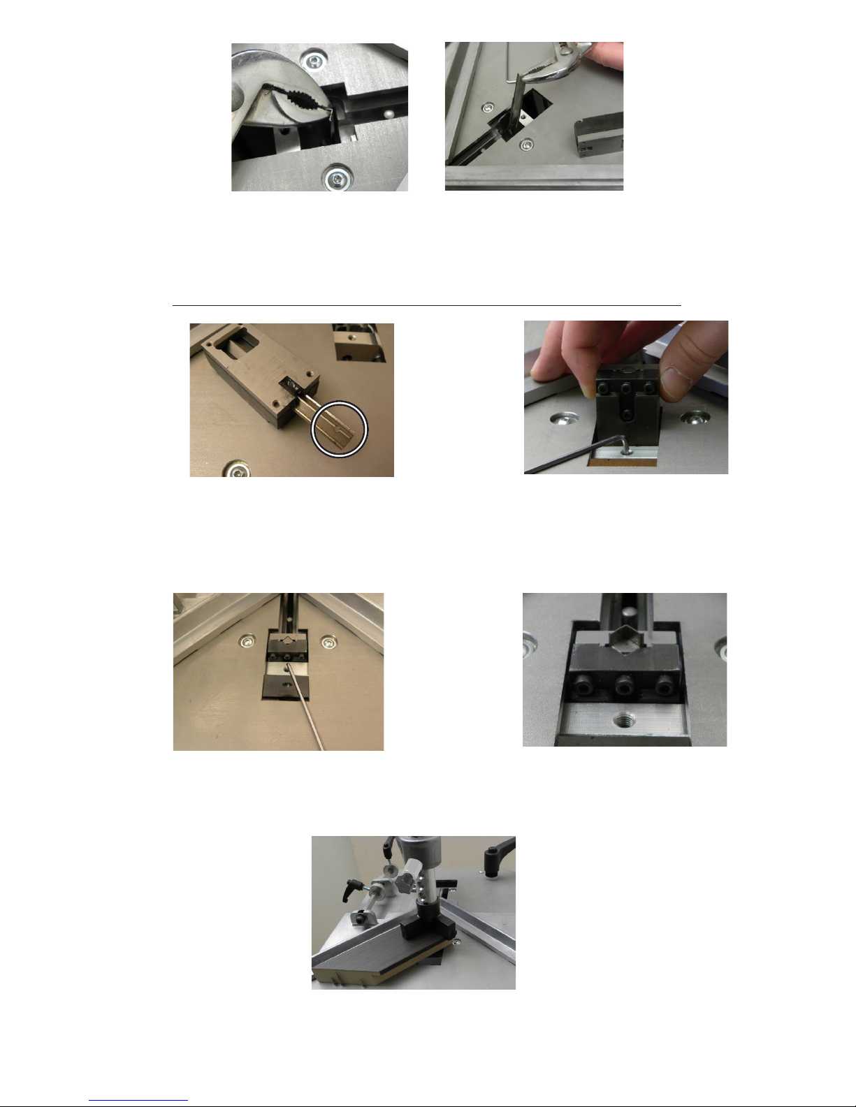
Take pliars to remove the wedge driver blade and twist it to unlock it.
DO NOT PULL IT STRAIGHT UP !
Apply some grease at the bottom
of the wedge distributor block and
insert a new wedge driver blade into
the block with its hole (in the circle)
downwards.
Replace the wedge distributor block in
its housing with the window towards the
cartridge channel and install the wedge
distributor block. Then, lock it using the
2,5mm Allen key.
1. 2.
D) INSTALLATION OF A NEW WEDGE DRIVER BLADE
Push the wedge driver blade fully in with a piece of wood or moulding
; press the pedal to engage the wedge driver blade entirely.
Check the wedge driver blade installation, it should slide smooth with
no resistance.
The upper end of the wedge driver blade
stays out of the block. Reinstall the magnetic
adjustable rod clamp assembly in order to
proceed with the following step.
3.
4.
5.
Tighten the screw of the wedge
distributor block paying attention to
level it with the working table.
Non contractual document - Cassese France® - Document non contractuel
12
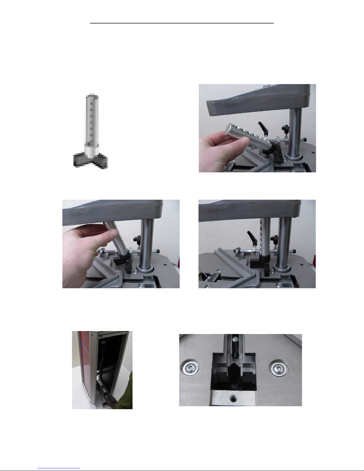
E) UNJAMMING OF THE WEDGE DISTRIBUTOR BLOCK
-Try to pull up the wedge distribution block. If it still doesn’t come out, then call your
distributor for further instructions.
If you have succeeded in removing the wedge distributor block :
-If the old wedge driver blade is stuck in the wedge distributor block :
PERFORM THE PROCEDURE B STEP 1 TO STEP 5,
THEN PROCEED TO PROCEDURE E COMPLETELY.
-If the old wedge driver blade is damaged and remains in the machine :
PERFORM THE PROCEDURE B STEP 1 TO STEP 5,
THEN PROCEED TO PROCEDURE C + D COMPLETELY.
If the wedge driver blade or a wedge is jamming your wedge distributor block, please
follow this procedure :
-Remove the cartridge located inside the underpinner, and the magnetic adjustable rod
clamp assembly.
-If the cartridge doesn’t come out, loosen the screw of the wedge distributor block with a
2.5mm Allen key, unlock the handle for loading wedges 3 and remove the sliding table E.
-Pull up the wedge distributor block. If the cartridge was jammed inside, ask for the help
of someone to turn the handle for loading wedges 3. Then pull up the wedge distribution
block and the cartridge.
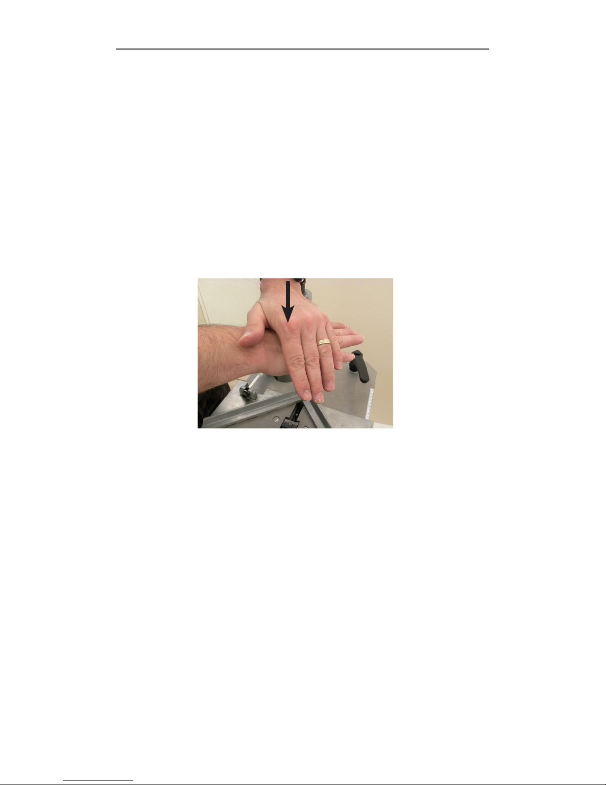
-If the wedge distributor block doesn’t come out, perform a quick hard compression on
the crossbar as in the picture.
 Loading...