

Caslon Zip21A Operation And Maintenance Manual
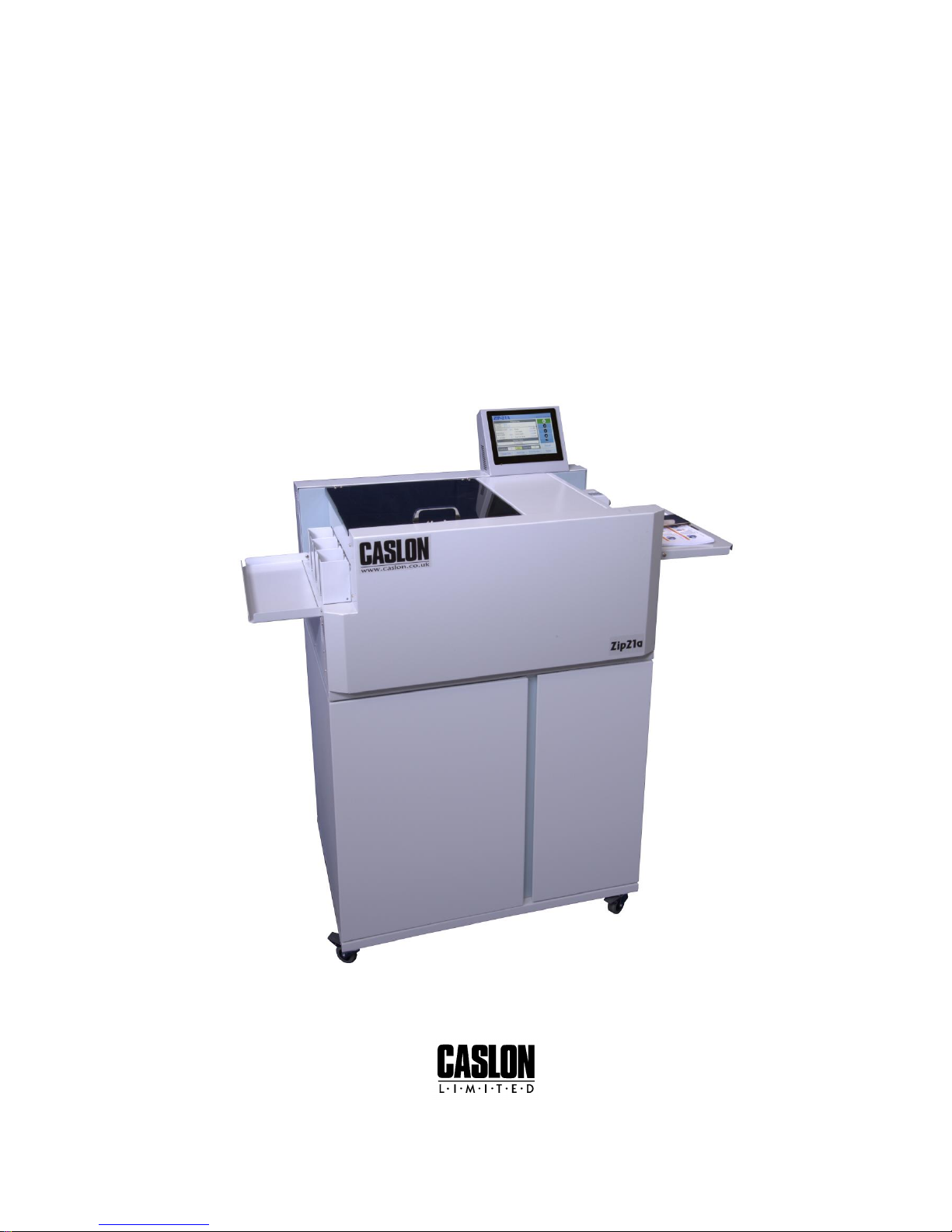
Zip21A
Operation and Maintenance Manual
01-03-15 onwards 1502005
Caslon House, Lyon Way, Hatfield Road, St. Albans, Herts, AL4 0LB / UK
Telephone: +44 (0)1727-852211 Fax: +44 (0)1727-855772
Email: info@caslon.co.uk Website: www.caslon.co.uk

Page 1
Contents
.............................................................................................................. 2
..................................................................................................... 3
................................................................ 3
.............................................................................. 4
.......................................................................................... 5
..................................................................................................... 5
............................................................................................................. 6
............................................................................. 7
.......................................................................................... 8
......................................... 9
.............................................................................................................. 10
............................................................................. 11
.......................................................................................... 12
............................................................................................... 12
............................................................................ 13
...................................................................................................................... 14
.................................................................................................................. 14
................................................................................ 15
......................................................................................... 15
.............................................................................. 16
........................................................ 17
..................................................................................................... 18
..................................................................................................... 19
..................................................................................................... 20
..................................................................................................... 21
..................................................................................................... 22

Page 2
Specifications
Maximum Paper Size:
320mm x 470mm
15.5" x 18.5”
Minimum Paper Size:
145mm x 145mm
5.7" x 5.7"
Maximum Paper thickness:
350gsm (0.5mm)
115 lb. Cover
Cutting Speed:
288 finished cards per minute.
Cross Cut Method:
Programmable guillotine
Maximum Cross Cuts per Sheet:
99
Minimum Size of Cross Cut Gutter:
2mm
0.080"
Recommended Bottom Trim Off:
4mm – 10mm
0.160" - 0.3937"
Centre Slit Gutter:
6mm
0.275"
Inline Cut Method:
Rotary, spring loaded slitting knives
Maximum Paper Capacity:
~ 200mm
~ 7.87"
Feeding Method:
Suction, top feed
Delivery Method:
Adjustable receiving tray
Physical Size:
(including feed tray)
1100mm long x
680mm wide x
1100mm high
43.3" long x
26.8" wide x
43.3" high
Shipping Size:
950mm long x
700mm wide x
1500mm high
31.5" long x
25.6" wide x
21.6" high
Net Weight:
115 kilos
253 lbs
Shipping Weight:
135 kilos
297 lbs.
Power:
AC 220V, 50 Hz
Auxiliary Parts supplied with machine:
Instruction Manual
Power Cord
Delivery Tray Dividers
Hex T type 2.5mm wrench
Screw Driver
Vernier Callipers
Card width adjusting tool

Page 3
Safety Information
Read and understand all instructions in this manual before attempting installation, operation or
general maintenance of the Zip21A.
Assemble the machine as outlined in the “Initial Machine Assembly” section
Use only a grounded electrical outlet when connecting the Zip21A to a power source. If you are
unsure, check with a qualified electrician – see “Important information before you start” below.
Observe all warnings and instructions marked on the Zip21A.
Unplug the Zip21A from wall outlets before cleaning or maintenance.
Do not install or operate the Zip21A near water or whilst you are wet.
Make sure the Zip21A is installed on a secure and stable surface.
Make sure the power cord does not obstruct walkways near the Zip21A.
Keep long hair and jewellery clear whilst operating the Zip21A.
Never operate the Zip21A with any guarding removed.
Always disconnect the power to the Zip21A whilst not in use.
If you are in any doubt about the operation of the Zip21A, please call your local service agent.
Important Information before you start
The Zip21A is a microprocessor-controlled machine. As such, the Zip21A must be connected to
a dedicated, clean power supply. The Zip21A may be unable to perform correctly and
consistently if it is connected to a power supply with other equipment.
A power surge protector should be used with the Zip21A to protect the electronics. Electronics
that are damaged due to power surges are not covered under the standard warranty.
The Zip21A is sold in Europe as a 230V machine with the correct power cord provided.
The user is also solely responsible to assure that the Zip21A is not connected to the wrong
voltage. Damage caused by incorrect voltage hook-up is not covered under the standard
warranty.
We recommend that the Zip21A box and packing materials be kept. While service parts are
available from your dealer and can typically be easily replaced in the field, it may be necessary
to return the Zip21A to the factory for complex service. The Zip21A box and packing material
have been designed to protect the machine from normal handling during transportation.

Page 4
Product Recycling and Disposal
European Union - Disposal Information for Commercial Users
Application of this symbol on your equipment is confirmation that you must dispose of this
equipment in compliance with agreed national Procedures.
In accordance with European legislation end of life electrical and electronic equipment subject
to disposal must be managed within agreed procedures.
Prior to disposal please contact your local dealer or Xerox representative for end of life take
back information.
European Union - Disposal Information for Domestic Users
Application of this symbol on your equipment is confirmation that you should not dispose of
the equipment in the normal household waste stream.
In accordance with European legislation, end of life electrical and electronic equipment
subject to disposal must be segregated from household waste.
Private households within EU Member States may return used electrical and electronic
equipment to designated collection facilities free of charge. Please contact your local disposal
authority for information.
In some Member States when you purchase new equipment your local retailer may be required
to take back your old equipment free of charge. Please ask your retailer for information.
Countries not within the European Union
Please contact your local waste authorities and request disposal information.

Page 5
Initial Machine Assembly
Remove both pieces from packaging and store for safe keeping.
Place the top unit onto the lower base and locate the rubber feet from the top unit into the
holes in the top of the base unit..
General Operation
Make sure that the Waste Collection Box, Delivery Dividers, Feed Tray and guards are all
properly installed on the Zip21A before operation.
The top guard MUST be closed properly or the safety switch will not be activated.
The main power switch, located at the delivery end/non-operator side of the machine, is used to
turn the Zip21A "ON". Once power has been turned on, the Zip21A will go through a self-test
sequence.
At the end of this self-test, the Zip21A will be ready to operate. The last set of program
parameters that were programmed into the Zip21A will automatically be recovered from
memory and displayed on the touch screen.
Pressing the "START" button will activate the Zip21A and the machine will start feeding paper.
When the machine has finished feeding all of the stock and the feed tray is empty, it will stop
automatically. Likewise, if a Run Count is set the machine will feed the correct number of sheets
and then automatically stop.
Pressing the "STOP" button will deactivate the feeding system of the machine and complete the
sheet currently being processed.
If an error occurs, the Zip21A will sound a warning and stop the machine. An error message
should be displayed on the touch screen display. Note the error message and refer to the
“Errors” section. To clear the error, follow the procedure indicated until the machine returns to
operation. The Zip21A will not operate until the error message has been cleared.

Page 6
Feeder Section
The Zip21A uses a suction feeder that feeds from the top. The lead edge of the stack in the
feeder should be pushed against the stop plate, under the suction unit.
The position of the top of the stack in relation to the suction unit is controlled by the blue cap
knob situated above the feeder section. It has a scale on top that denotes the size of the gap
and a red slider that indicates the position selected. Clockwise rotation decreases the gap and
anti-clockwise rotation increases the gap.
A chrome rear guide is fitted and is adjustable for different lengths of stock. Undo the black
knob and adjust the backstop so that is just touches the rear of the stock. This chrome rear
guide also raises up to allow access to install/remove the sheets and to make adjustments to
the sheet retarding plate adjuster.
Below the feed unit is the sheet retarding plate adjuster. This also has a black knob and adjusts
the gap between the top of the sheet retarding plate and the suction drive belt. This should be
adjusted `to allow one sheet at a time to be fed. Clockwise rotation decreases the gap and anticlockwise rotation increases the gap.
To adjust for different widths of paper use the Paper Width Position Thumb Wheel situated on
the non-operator side of the feeder.
To adjust the position of the paper in the feeder use the Left / Right Adjustment Dial situated
on the operator side of the feeder.
:
The sensor at the front of the Paper Feed Tray may cause an error if it detects excess light or
direct sunshine. Keep machine out of direct light.
 Loading...