

Casi Rusco 97X, 94X Users Guide

CASI-RUSCO...Security Solutions for the 21stCentury
Model 94x, 97x
Proximity Reader
Installation Guide
CASI
RUSCO
791 Park of Commerce Boulevard
Boca Raton, Florida 33487
(561) 998-6100
Part Number: 460157001L
January 2002

This publication may contain examples of data reports used in daily
business operations. Examples include fictitious names of
individuals and companies for illustration only; any similarity to
names and addresses of actual business enterprises and persons is
entirely coincidental.
This document is distributed on an as is basis, without warranty
either expressed or implied. Successful implementation depends
solely upon the customer’s ability to integrate each product into the
total inventory of “in-house” products. While each offering has been
reviewed for its compatibility and maintainability, no assurance of
successful installation can be given.
The customer accepts full maintenance responsibility. (A full scope
of software and hardware maintenance contracts are available to the
customer.)
Copyright 1993, 1994, 1997-2002 CASI-RUSCO
All Rights Reserved
Printed in the USA
ProxLite is a trademark of CASI-RUSCO.
WARNING: This is a Class A product. In a domestic environment, this
product may cause radio interference; in which case, the user may be
required to take adequate measures.

Contents
Introduction................................................................................................. 1
Product Features......................................................................................... 2
Switch Settings............................................................................................ 3
Selecting Reader Power Level.....................................................3
Selecting Operating Mode ...........................................................7
Selecting Beeper Sound Level .....................................................7
Connecting the Reader .............................................................................. 8
CE/FCC Compliancy ...................................................................8
Pinouts..........................................................................................10
Wiring Diagrams.........................................................................10
Mounting the Reader ............................................................................... 17
Testing the Reader.................................................................................... 28
Troubleshooting Guide............................................................................ 29
All Installations ...........................................................................29
Unsupervised Modes Only........................................................31
Supervised Modes Only.............................................................31
Technical Specifications........................................................................... 34
Functional Specifications......................................................................... 36
Model 94x, 97x Proximity Reader
i

Figures
Figure 1: Model 94x/97x Reader, J1 Connector and DIP Switch
Locations.........................................................................4
Figure 2: Typical Installation Using Shielded Cable/Drain Wire .... 8
Figure 3: Wiring Diagram, Model 94x/97x Supervised
F/2F Mode .....................................................................11
Figure 4: Wiring Diagram, Model 94x/97x Unsupervised
F/2F Mode .....................................................................13
Figure 5: Wiring Diagram, Model 94x/97x Unsupervised Wiegand
Mode ........................................................................... 15
Figure 6: Recommended Additional Mounting Instructions
for External Tamper Switch Activation ..........................19
Figure 7: Model 940 Reader - Gang Box Mounting..................... 20
Figure 8: Model 940 Reader - Direct Wall Mounting ................... 21
Figure 9: Model 941 Reader - Gang Box Mounting..................... 22
Figure 10: Model 941 Reader - Direct Wall Mounting ................... 23
Figure 11: Model 970/972 Reader - Gang Box Mounting.............. 24
Figure 12: Model 970/972 Reader - Direct Wall Mounting ............ 25
Figure 13: Model 971/973 Reader - Gang Box Mounting.............. 26
Figure 14: Model 971/973 Reader - Direct Wall Mounting ............ 27
Figure 15: Badge to Reader Presentation..................................... 36
ii
Model 94x, 97x Proximity Reader

Introduction
This manual is an installation guide for the CASI-RUSCO Models
940, 941, 970, 971, 972, and 973 Proximity Perfect Readers.
Throughout this guide, the abbreviation 94x represents Reader
Models 940 and 941. The abbreviation 97x represents Reader Models
970, 971, 972, and 973.
The 94x and 97x Readers while similar in functionality offer a variety
of features making them suitable for different applications. The 94x
and 97x Readers are designed tomount on standard U.S. gang boxes.
The 94x Readers are single-gang box size. The 97x Readers are sized
for larger dual gang box installation, offer greater badge read range,
and a keypad option.
Models 940 and 970 give the greatest all-around badge read range for
their respective sizes, making them ideal for most installations.
Models 941 and 971 are tuned for installation on metal mounting
plates. The standard metal mounting plate shields the reader from
the effects of a metal wall, which would otherwise dramatically
reduce the read range. The optional back-to-back metal mounting
plate shields the readerfrom the effects ofametal wall and makes the
reader unidirectional; ideal for direct back-to-back reader
installations.
Models 972 and 973 are dual gang size readers, identical to the 970
and 971 respectively, except for their built-in twelve-position keypad.
This feature makes these readers ideal for installations requiring
keypad PIN entry in addition to a valid badge read.
Model 94x, 97x Proximity Reader 1

Product Features
The CASI-RUSCO Model 94x/97x Proximity Perfect Reader offers:
• State-of-the-art architecture.
TM
• The ability to read all Proximity Perfect, ProxLite
badges and key tags.
• Proximity Perfect badge read ranges up to 10 inches (254 mm) for
970 Readers and up to 8 inches (203 mm) for 940 Readers (See
Table 2 “Read Range by Model Number,” on page 5).
• Field changeable DIP switches allow all 94x and 97x Readers to
operate in one of four distinct operating modes: Wiegand, F/2F,
Supervised, and Silent Supervised. Silent Supervised mode is
ideal for installations where no audible or visual indication of
communication loss with the microcontroller is desired at the
reader.
In the unsupervised modes, the reader communicates w ith the
microcontroller over a unidirectional Wiegand or F/2F data link
that carries Proximity Perfect badge data only.
In the supervised modes, the reader communicates with the
microcontroller over a bidirectional F/2F data link, that carries
the following:
Proximity Perfect badge data
Supervision messages
Exit request and door switch status
Microcontroller acknowledgments and commands
• Intelligent bidirectional communication between the reader and
microcontroller, which can be accomplished up to 5,500 feet.
• Weather-resistant housing for outdoor use.
• Standard 12V operation.
• A clear, logical user interface with three LEDs and a beeper.
• Rugged molded ABS construction with integral backplate.
• Built-in tamper alarm also detects removal from wall.
• External tamper alarm option.
• Tactile keypad (Models 972 and 973 only) for Personal
Identification Number (PIN) input.
• Switch selectable beeper enable/disable and volume control.
• UL verified for indoor use only.
,andEntrée
2 Model 94x, 97x Proximity Reader

Switch Settings
Two banks of four DIP switches located on the back of the reader are
used to select the r eader power level, operating mode, and beeper
sound level.
CAUTION: Power should be removed from the reader while switch
settings are changed.
Selecting Reader Power Level
The reader’s power requirement is sel ected using four DIP switches.
The optimum power level will vary with each installation. Higher
power levels give improved read range for Proximity Perfect badges,
while lower power levels allow greater cabling distance between the
reader and the microcontroller. A detailed explanation is provided
below. The figure on the next page shows the location of the DIP
switches. The tables that follow the figure give the switch settings
along with the read ranges and cable distances.
Explanation of Read Range/Cable Distance/Power Level:
Maximum badge read range is determined by the distance at which
the field transmitted by the reader is just strong enough to wake up the
badge. Therefore, the higher the reader’s transmission power, the
greater the badge read range will be. The trade-off for increased read
range is a decrease in the maximum cabling distance between the
reader and the microcontroller. The trade-off between read range and
cabling distance is common to all proximity badge readers. The
power selection switches on the 94x/97x readers allow the optimum
power setting to be selected to suit individual installations.
Model 94x, 97x Proximity Reader 3
For example: On the high power setting, giving the greatest badge
read range, the reader typically requires 200mA of supply current
from the microcontroller. If there is 1,000 feet of 22-AWG cable
between the reader and the microcontroller, the total reader power
and power return path is 2,000 feet. Since 22-AWG cable has a typical
resistance of 16 ohms per 1,000 feet, the total resistance in the reader’s
power and power return wire is 32 ohms. By Ohms Law (V=IR), it
follows that the total voltage dropped in the reader power and power
return wires will be 6.4V (6.4V = 200mA x 32 Ohms). Therefore, the
reader supply voltage will drop from 12V at the microcontroller to
5.6V (12V - 6.4V) at the reader. Such a supply voltage is too low for
the reader to function reliably.
If the low power setting is selected, the badge read range is reduced.
However, the reader now typically requires only 75mA of supply
current; therefore, the voltage drop in the power and power return
wires is much less. In this case, the reader supply voltage will only be
reduced to 9.6V; high enough for reliable operation.
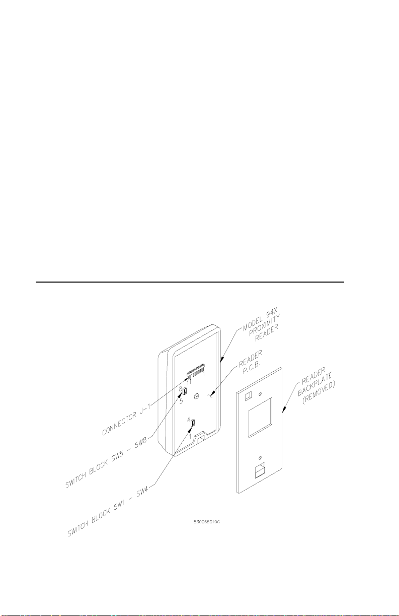
FIGURE 1: Model 94x/97x Reader, J1 Connector and
DIP Switch Locations
4 Model 94x, 97x Proximity Reader
CAUTION: Power should be removed from the reader while switch
settings are changed.
The table below shows the switch settings for each of the three power
levels.
TABLE 1: Power Level Switch Settings
Power
Level
Switch 1 Switch 2 Switch 3 Switch 4
LOW OFF ON ON OFF
MEDIUM ON OFF OFF ON
HIGH ON ON ON ON
The table below gives the read ranges for each of the readers based on
thepowerlevelsettings.Allreadrangesaretypicalmaximums.
TABLE 2: Read Range by Model Number
Power
Level
LOW 7 in
MEDIUM 9 in
HIGH 10 in
970 & 972 971 & 973 940 941
178 mm
229 mm
254 mm
5in
127 mm
6in
152 mm
7in
178 mm
5in
127 mm
7in
178 mm
8in
203 mm
4in
102 mm
5in
127 mm
6in
152 mm
in = inches
mm = millimeters
Model 94x, 97x Proximity Reader 5

The table below gives the maximum cabling distances between the
reader and the microcontroller for each of the three power levels.
TABLE 3: Cable Distances
Power
Level
LOW 5500 ft
MEDIUM 2200 ft
HIGH 600 ft
NOTES:
1. Reader supply voltage measured at microcontroller: 13.6V is
nominal when line powered, 12V is nominal when battery powered.
2. Not recommended for 12V, battery-backed installations.
3. All cable distances are typical maximums.
4. Readers powered by a local 12VDC power supply will have a
maximum cable distance of 5,500 feet (1676 m) of 22-AWG
telephone wire for all power level settings.
13.6 Volts (see Note 1)
18
AWG 22 AWG
2000 ft
1676 m
610 m
900 ft
671 m
274 m
250 ft
183 m
76 m
12Volts(seeNote1)
18
AWG 22 AWG
3500 ft
1067 m
1100 ft
335 m
1500 ft
457 m
450 ft
137 m
See Note 2 See Note 2
6 Model 94x, 97x Proximity Reader

Selecting Operating Mode
The table below shows the DIP switch settings for each of the four
operating modes.
TABLE 4: Operating Mode DIP Switch Settings
Operating Mode Switch 5 Switch 6
Wiegand
F/2F
Supervised F/2F
Silent supervised F/2F
NOTES:
1. In the Wiegand operating mode, 2801, 2804, and 3201 Proximity
Perfect badge data is sent using 2801, 2804, and 3201 Wiegand
format, respectively. Proximity Perfect badge data encoded using
the 40-bit format and ProxLite badge data is sent using 40-bit
Wiegand format. Keyboard information is sent using 8-bit Wiegand
format.
2. In operating modes other than Wiegand, Proximity Perfect badge
data is sent using a 10-digit F/2F format. Badge data for Proximity
Perfect badges encoded using the 40-bit format are sent using a
13-digit F/2F format. All ProxLite badge data is sent using a 12-digit
F/2F format.
1
2
2
2
OFF OFF
ON OFF
OFF ON
ON ON
Selecting Beeper Sound Level
The table below shows the DIP switch settings for the three beeper
sound levels.
TABLE 5: Beeper Sound Level DIP Switch Settings
Beeper Sound Level Switch 7 Switch 8
Normal ON ON
Low ON OFF
Off OFF ON
Model 94x, 97x Proximity Reader 7
Connecting the Reader
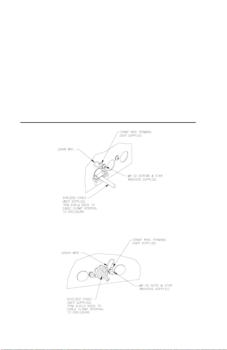
CE/FCC Compliancy
NOTE: As of January 1, 1996, all new European installations MUST be
CE compliant.
To make the Model 94x/97x Reader installation CE and FCC
compliant, the following condition must be met:
• The cable connecting the model 94x/97x Reader to the
Micro/5 must have its shield grounded at the Micro/5
according to Figure 2.
FIGURE 2: Typical Installation Using Shielded Cable/Drain Wire
8 Model 94x, 97x Proximity Reader
Outside Micro/5 Enclosure

Manufacturers Declaration
of Conformity
(Subject to the conditions on page 8)
Manufacturer’s
Name:
Manufacturer’s
Address:
EU Representative: Interlogix Europe & Africa
Product
Identification:
Means of Conformity: • Hereby, CASI-RUSCO, declares that this
CASI-RUSCO
791 Park of Commerce Boulevard
Boca Raton, FL USA 33487
Excelsiorlaan 28
B- 1930 Zaventum
Belgium
Product: Proximity Reader
Model Number: Model 94x/97x
Brand: CASI-RUSCO
equipment is in compliance with the essential
requirements and other relevant provisions of
Directive 1999/5/EC.
• Hierbij verklaart CASI-RUSCO dat het apparoat
in overeenstemming is met de essentiële eisen
en de andere relevante bepalingen van richtlijn
1999/5/EG.
• Par la présente CASI-RUSCO déclare que
l'appareil est conforme aux exigences
essentielles et aux autres dispositions
pertinentes de la directive 1999/5/CE.
• Hiermit erklärt CASI-RUSCO, dass sich diese
auspüstung in Übereinstimmung mit den
grundlegenden Anforderungen und den
anderen relevanten Vorschriften der Richtlinie
1999/5/EG befindet". (BMWi)
Notices: Approved for use in the following countries:
A
B
CZ
DK
FIN
F
D
GR
H
IS
IRL
I
LU
NL
N
PL
P
E
S
CH
GB
Model 94x, 97x Proximity Reader 9

Pinouts
The table below shows the pinouts for connecting the reader to the
microcontroller. Connector J1, pin 1 is to the right as you view the
connector from behind the reader. See Figure 1, “Model 94x/97x
Reader, J1 Connector and DIP Switch Locations,” on page 4.
TABLE 6: Pinouts
Connector
J1 Pin #
1+12VDC Red
2Ground Black
3 Red LED External Drive Blue
4 Green LED External Drive Brown
5 Yellow LED External Drive Orange
6 Reader Data 0 Green
7 Reader Data 1 White
8 Beeper External Drive Violet
9 Keying Pin
10 Door DI (Door Contact Switch) Yellow
11 Exit DI (Exit Request Button) Gray
Signal
Wiring Diagrams
Pigtail Wire
Color
See the wiring diagrams that follow for details on connecting the
reader to the microcon troll er based on the mode of the reader.
10 Model 94x, 97x Proximity Reader
 Loading...