

Page 1

CASI-RUSCO...Security Solutions for the 21stCentury
Model 840/845
Contactless
Smart Card Reader
Installation Guide
CASI
RUSCO
791 Park of Commerce Boulevard
Boca Raton, Florida 33487
(561) 998-6100
Part Number: 460394001D
January 2002
Page 2

This publication maycontain examples of data reports used in daily
business operations. Examples include fictitiousnames of individuals
and companies forillustration only; any similarity to names and
addresses of actual business enterprises and personsis entirely
coincidental.
This document is distributed on an as is basis, without w arranty either
expressed or implied. Successful implementation depends solely upon
the customer’s ability to integrate each product into the total inventory
of “in-house” products. While each offering has been r eviewed for its
compatibility and maintainability, no assurance of successful
installation can be given.
The customer accepts full maintenance responsibility. (A f ull scope of
software and hardware maintenance contracts are available to the
customer.)
Copyright 1999 - 2002
CASI-RUSCO
All Rights Reserved
Printed in the USA
Proximity Perfect is a trademark of CASI-RUSCO.
mifare 1 is a trademark of Philips.
WARNING
This is a Class A product. In a domestic environment this product
may cause radio interference in which case the user may be required
to take adequate measures.
Page 3

Contents
Figures................................................................................................................ ii
Introduction....................................................................................................... 1
Product Features ............................................................................................... 2
Installation Steps............................................................................................... 3
Mounting the Reader........................................................................................ 3
Connecting the Reader..................................................................................... 6
Cabling Distances ................................................................................6
Pinouts ..................................................................................................7
Communications Settings................................................................................ 9
Testing for Current Settings...............................................................9
Setting the Communications Mode (CASI-RUSCO M ode)......... 10
Setting the Communications Mode (Native Mode) ..................... 11
Digital Input (Door Contact and Exit Request)
Supervised F/2F Mode Only ................................................................ 13
Testing the Reader .......................................................................................... 22
Troubleshooting Guide .................................................................................. 23
Technical Specifications ................................................................................. 26
Functional Specifications ............................................................................... 27
CE Certification ................................................................................................30
Models 840/845 Contactless Smart Card Reader i
Page 4

Figures
Figure 1: Model 84x Reader - Gang Box Mounting ....................... 4
Figure 2: Model 84x Reader - Wall Mounting................................ 5
Figure 3: Model 84x Reader, J2 Connector Location.................... 8
Figure 4: Wiring Diagram, Model 84x - Supervised F/2F Mode .. 14
Figure 5: Wiring Diagram, Model 84x - Wiegand 4001 Mode ..... 16
Figure 6: Wiring Diagram, Model 84x -Unsupervised F/2F
Mode .............................................................................18
Figure 7: Wiring Diagram, Model 84x - Omron/Magstripe
Strobe Mode................................................................. 20
ii
Model 840/845 Contactless Smart Card Reader
Page 5

Introduction
This manual is an installation guide for the CASI-RUSCO Model 840/845
Contactless Smart Card Reader. Throughout this guide, the abbreviation
84x will stand for reader Models 840 and 845.
The 84x Reader is designed to mount on a standard U.S. single electrical
gang box.
The Model 845 is identical to the Model 840 except for a built-in twelve
positionkeypad.Thisfeaturemakesthisreaderidealforinstallations
requiring keypad PIN entry in addition to a valid smart card read.
Model 840/845 Contactless Smart Card Reader 1
Page 6

Product Features
The CASI-RUSCO Model 840/845 Contactless Smart Card Reader offers
the following features:
• State-of-the-art architecture.
®
• The ability to read all MIFARE
• The ability to read the unique serial number of a MIFARE
convert the hex format to twelve digits Binary Coded Decimal (BCD).
• Supervised communications with the microcontroller over a
bidirectional F/2F data link that carries the following:
• Contactless smart card ID data
• Supervision messages
• Exit request and door switch status
• Microcontroller acknowledgm e nts and commands
• Intelligent bidirectional communication between the reader and
microcontroller, which can be accomplished over 4-conductor
telephone cable.
• Weather-resistant housing for outdoor use.
• Standard 12V operation.
• A clear, logical user interface with three LEDs and a beeper.
• Rugged, molded polycarbonate construction with integral backplate.
• Built-in tamper alarm.
• Two supervised digital switch inputs for interfacing exit request and
door contact switches.
•Externaltamper.
• Installer programmable communications selector:
• Supervised F/2F communications.
• Unsupervised F/2F communications.
• Omron/Magstripe Strobe communications.
• Wiegand 4001 communications.
• RS-232, 9600 8/N/1 communications.
• UL verified for indoor use only.
1 type Contactless Smart Cards.
®
1cardand
2 Model 840/845 Contactless Smart Card Reader
Page 7

Installation Steps
The following is the general sequence of steps to follow in installing the
84x Reader. Each step is explained in further detail in the sections that
follow.
1. Mount the reader backplate only (the reader will be m ounted later).
Refer to “Mounting the Reader” below.
2. Connect the reader. Refer to “Connecting the Reader” on page 6.
3. Mount the reader to the backplate. Refer to “Mounting the Reader”
below.
4. Test t he reader. Refer to “Testing the Reader” on page 22.
5. If necessary, refer to “Troubleshooting Guide” on page 23 for
troubleshooting information.
Mounting the Reader
The reader comes with a backplate suitable for mounting directly onto a
standard U.S. electrical single-gang box. The reader may also be mounted
directly onto a hollow wall. The reader is supplied with a weatherresistant gasket.
The figures listed below begin on the next page. Refer to the appropriate
figure fo r the type of reader you are mounting.
Figure 1, “Model 84x Reader - Gang Box Mounting,” on page 4.
Figure 2, “Model 84x Reader - Wall Mounting,” on page 5.
Model 840/845 Contactless Smart Card Reader 3
Page 8
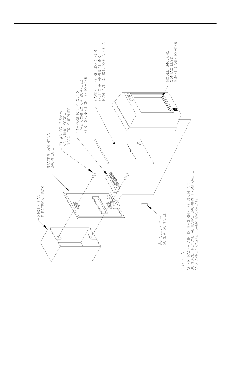
FIGURE 1: Model 84x Reader - Gang Box Mounting
4 Model 840/845 Contactless Smart Card Reader
Page 9

FIGURE 2: Model 84x Reader - Wall Mounting
Model 840/845 Contactless Smart Card Reader 5
Page 10

Connecting the Reader
Cabling Distances
The table below gives the maximum cabling distances between the reader
and the microcontroller.
TABLE 1: Cable Distances
13.6 Volts (see Note 1)
18
AWG 24 AWG
2750 ft
838m
NOTES:
1. Reader supply voltage measured at microcontroller: 13.6V is nominal
when line-powered; 12V is nominal when battery-powered.
2. All cable distances are typical maximums.
3. Readers powered by a local 12VDC power supply will have a maximum
cable distance of 500 feet (152m) of 24 AWG telephone wire.
4. The reader will work well with unshielded cable in most environments.
No company can guarantee that data will be reliably transmitted for long
distances on unshielded cable in every installation. Typical Wiegand
reader installation requires eight-conductor shielded cable to provide
reader power, controller communication, door contact, exit push
button, and tamper switch status. The same functionality is provided by
Proximity Perfect readers, "supervised" with four-conductor unshielded
cable.
750 ft
229m
12Volts(seeNote1)
18
AWG 24 AWG
2000 ft
610m
500 ft
152m
6 Model 840/845 Contactless Smart Card Reader
Page 11

Pinouts
The table below shows the pinouts for connecting the reader to the
microcontroller. Connector JP2, pin 1 is to the right as you view the
connector from behind the reader. See Figure 3, “Model 84x Reader, J2
Connector Location,” on page 8.
TABLE 2: Pinouts for Connector J2
J2 Pin Signal
10
11
1
2
3
4
5
6
7
8
9
+12VDC
Ground
Green LED
RS-232 Output
No Connection
Reader Data
Reader Data 1
Door DI (Point)
Door DI (Return)
Exit DI (Point)
Exit DI (Return)
Model 840/845 Contactless Smart Card Reader 7
Page 12

FIGURE 3: Model 84x Reader, J2 Connector Location
8 Model 840/845 Contactless Smart Card Reader
Page 13

Communications Settings
Testing for Current Settings
Perform the following steps to test for current settings:
NOTE: RS-232 mode for Revision B printed circuit boards and higher.
1. Remove power from the reader.
2. Place a mini-jump over both pins of JP4.
3. Add power to the reader and listen for the number of beeps.
NOTE: The number of beeps indicate the current communications mode
set.
• 1 beep = Supervised F/2F
• 2 beeps = Unsupervised F/2F
• 3 beeps = Strobe
• 4 beeps = Wiegand 4001
• 5 beeps = RS-232
4. Remove power from the reader.
5. Place a mini-jump over one (1) pin of JP4.
6. Add power to the reader and resume normal operations.
Model 840/845 Contactless Smart Card Reader 9
Page 14

Setting the Communications Mode (CASI-RUSCO Mode)
In CASI-RUSCO mode, the reader splits the serial number into two parts
for Wiegand formatting. The other communication modes return the
number resulting from this split format. In this manner, all five output
formats yield the same number to the system. This number will not match
theserialnumberprovidedbythecardmanufacturer.
The following steps are for setting the communications mode in
CASI-RUSCO mode.
NOTE: RS-232 mode for Revision B printed circuit boards and higher.
1. Remove power from the reader.
2. Place a mini-jump over both pins of JP4; JP3 is open.
3. Add power to the reader and li sten for the number of beeps.
NOTE: The number of beeps indicate current communications mode
set.
• 1 beep = Supervised F/2F
• 2 beeps = Unsupervised F/2F
• 3 beeps = Strobe
• 4 beeps = Wiegand 4001
• 5 beeps = RS-232
4. Push and release the tamper switch the number of times that
correspond to the communications mode desired.
NOTE: If you exceed the number of pushed listed below, an error
response will sound and flash. Simply repeat this step.
Modes:
• 1 push = Supervised F/2F
• 2 pushes = Unsupervised F/2F
•3pushes=Strobe
• 4 pushes = Wiegand 4001
• 5 pushes = RS-232
5. Wait 5 seconds and then remove power from the reader.
10 Model 840/845 Contactless Smart Card Reader
Page 15

6. Place a mini-jump over one (1) pin of JP4; JP3 remains open.
7. Add power to the reader and resume normal operations.
Setting the Communications Mode (Native Mode)
In Nat ive Mode, the reader uses a straight binary to BCD conversion of
the serial number to match the serial number given by the card
manufacturer.
The following steps are for setting the communications mode in Native
Mode.
NOTE: RS-232 mode for Revision B printed circuit boards and higher.
1. Remove power from the reader.
2. Place a mini-jump over both pins of JP4 and JP3.
3. Add power to the reader and listen for the number of beeps.
NOTE: The number of beeps indicate current communications mode
set.
• 1 beep = Supervised F/2F
• 2 beeps = Unsupervised F/2F
• 3 beeps = Strobe
• 4 beeps = Unused
• 5 beeps = RS-232
4. Push and release the tamper switch the number of times the
correspond to the communications mode desired.
NOTE: If you exceed the number of pushes listed below, an error
response will sound and flash. Simply repeat this step.
Modes:
• 1 push = Supervised F/2F
• 2 pushes = Unsupervised F/2F
•3pushes=Strobe
• 4 pushes = Unused
•5pushes=RS-232
Model 840/845 Contactless Smart Card Reader 11
Page 16

5. Wait 5 seconds and then remove power from the reader.
6. Place a mini-jump over one (1) pin of JP4 and remove JP3.
7. Add power to the reader and resume normal operations.
NOTE: Mode 4 is not available in Native Mode. Beeping and flashing
LEDs indicate that Mode 4 has erroneously been set in Native Mode.
12 Model 840/845 Contactless Smart Card Reader
Page 17

Digital Input (Door Contact and Exit Request) Supervised F/2F Mode Only
The door contact (alarm) and exit request are both configured for 4-state
reporting. If used, then end-of-line resistors (two at 1,000 ohms each) are
required.
1. Install the door contact and the two end-of-line resistors
(installer-supplied) at the contact.
2. Wire the door contact/end-of-line resistors to pin JP2-8 and pin JP2-9.
3. Install the exit request contact and the two end-of-line resistors
(installer-supplied) at the contact.
4. Wire the exit request/end-of-line resistors to pin JP2-10 and
pin JP2-11.
Model 840/845 Contactless Smart Card Reader 13
Page 18

FIGURE 4: Wiring Diagram, Model 84x - Supervised F/2F Mode
14 Model 840/845 Contactless Smart Card Reader
Page 19

installed at the microcontroller’s terminal block. A resistor is supplied with the reader. MicroProx does not require
this resistor.
of Micro/5 cabinets using 14 AWG wire. No shield connections at the reader.
side of the power supply must be connected to the micro (pin 2 on the reader port). Keep the wiring from power
supply to reader less than 50 feet.
NOTES (Unless otherwise specified):
1. A 470-ohm, 1/2W, pull-up resistor is required between +12VDC and READER DATA 1. The pull-up resistor should be
2. Shielded cable is recommended in electrically noisy environments.
3. If using shielded cable, connect all shields together at the micro end. Connect to ground stud in the lower left corner
4. If using a local power supply, do not connect +12V line from the microcontroller to the reader. However, the negative
5. Refer to the appropriate system manual to determine whether this connection is required for door switch operation.
6. Blocking diodes may be 1N4148 or similar (installer supplied) and located in a secured area.
7. Protection diodes may be 1N4002, 1N4003, or 1N4004 (installer supplied) for the door strike assembly.
8. Fuse, power supply, door strike, and relay are provided by the installer.
Model 840/845 Contactless Smart Card Reader 15
Page 20
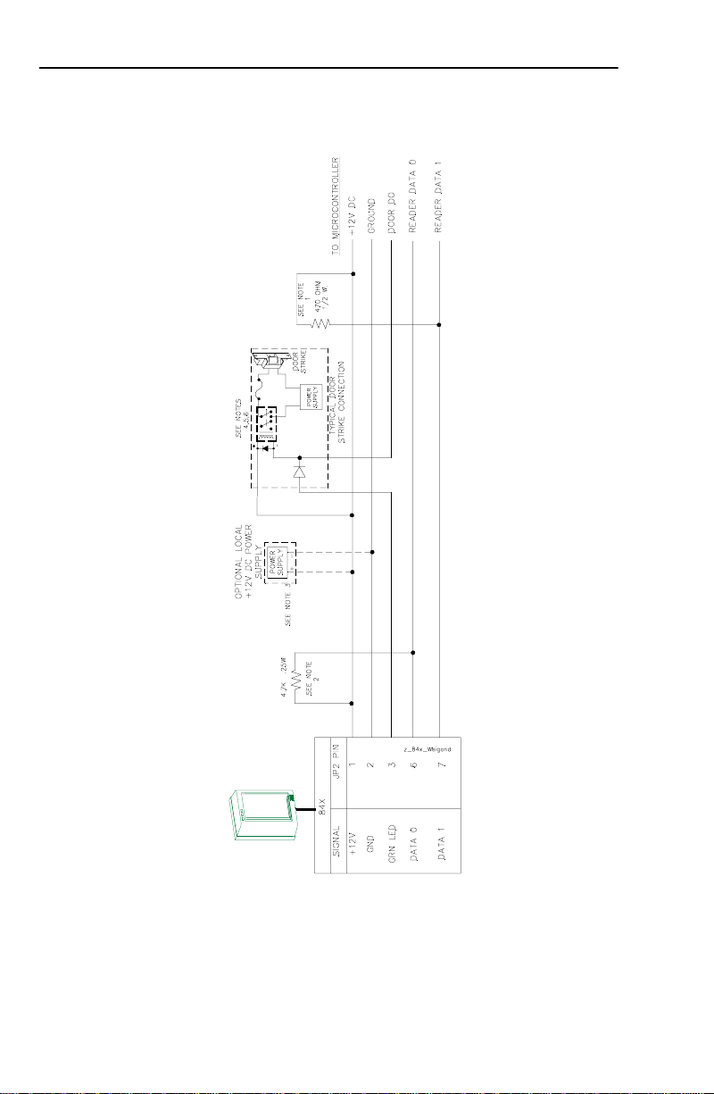
FIGURE 5: Wiring Diagram, Model 84x - Wiegand 4001 Mode
16 Model 840/845 Contactless Smart Card Reader
Page 21

installed at the microcontroller’s terminal block. A resistor is supplied with the reader. MicroProx may not require
this resistor.
installed at the microcontroller’s terminal block. A resistor is supplied with the reader. MicroProx may not require
this resistor.
side of the power supply must be connected to the micro (pin 2 on the reader port). Keep the wiring from power
supply to reader less than 50 feet.
NOTES (Unless otherwise specified):
1. A 470 ohm, 1/2W, pull-up resistor is required between +12VDC and READER DATA 1. The pull-up resistor should be
2. A 4.7K ohm, 1/4W, pull-up resistor is required between +12VDC and READER DATA 0. The pull-up resistor should be
3. If using a local power supply, do not connect +12V line from the microcontroller to the reader. However, the negative
4. Blocking diodes may be 1N4148 or similar (installer supplied) and located in a secured area.
5. Protection diodes may be 1N4002, 1N4003, or 1N4004 (installer supplied) for the door strike assembly.
6. Fuse, power supply, door strike, and relay are provided by the installer.
Model 840/845 Contactless Smart Card Reader 17
Page 22
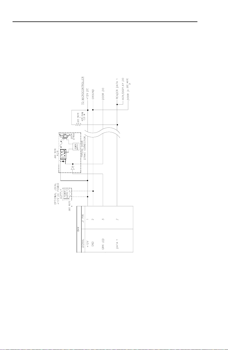
FIGURE 6: Wiring Diagram, Model 84x - Unsupervised F/2F Mode
18 Model 840/845 Contactless Smart Card Reader
Page 23

installed at the microcontroller’s terminal block. A resistor is supplied with the reader. MicroProx may not require
this resistor.
of Micro/5 cabinets using 14 AWG wire. No shield connections at the reader.
side of the power supply must be connected to the micro (pin 2 on the reader port). Keep the wiring from power
supply to reader less than 50 feet.
NOTES (Unless otherwise specified):
1. A 470-ohm, 1/2W, pull-up resistor is required between +12VDC and READER DATA 1. The pull-up resistor should be
2. Shielded cable is recommended in electrically noisy environments.
3. If using shielded cable, connect all shields together at the micro end. Connect to ground stud in the lower left corner
4. If using a local power supply, do not connect +12V line from the microcontroller to the reader. However, the negative
5. Refer to the appropriate system manual to determine whether this connection is required for door switch operation.
6. Blocking diodes may be 1N4148 or similar (installer supplied) and located in a secured area.
7. Protection diodes may be 1N4002, 1N4003, or 1N4004 (installer supplied) for the door strike assembly.
8. Fuse, power supply, door strike, and relay are provided by the installer.
Model 840/845 Contactless Smart Card Reader 19
Page 24
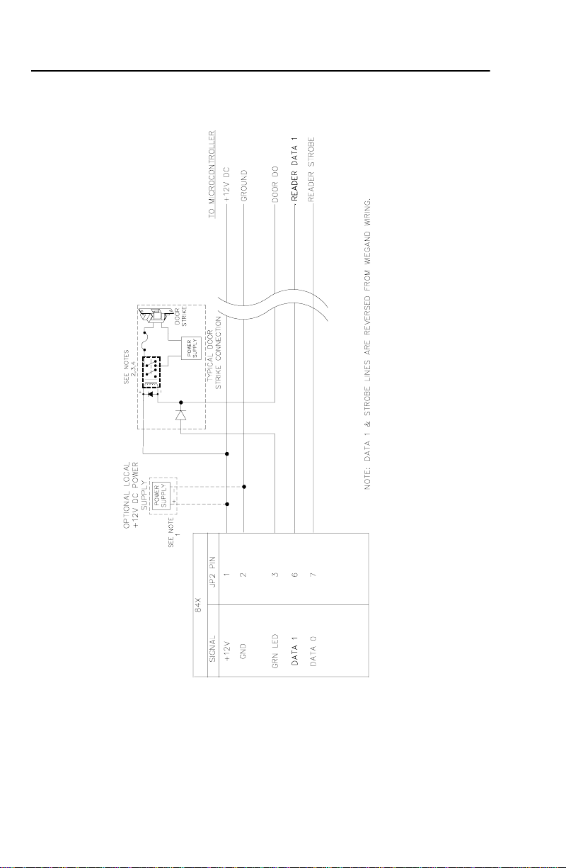
FIGURE 7: Wiring Diagram, Model 84x - Omron/Magstripe Strobe
Mode
20 Model 840/845 Contactless Smart Card Reader
Page 25

side of the power supply must be connected to the micro (pin 2 on the reader port). Keep the wiring from power
supply to reader less than 50 feet.
NOTES (Unless otherwise specified):
1. If using a local power supply, do not connect +12V line from the microcontroller to the reader. However, the negative
2. Blocking diodes may be 1N4148 or similar (installer supplied) and located in a secured area.
3. Protection diodes may be 1N4002, 1N4003, or 1N4004 (installer supplied) for the door strike assembly.
4. Fuse, power supply, door strike, and relay are provided by the installer.
Model 840/845 Contactless Smart Card Reader 21
Page 26

Testing the Reader
Follow the steps below to verify that the reader is working correctly.
1. Check all cabling and electrical connections from the reader to the
microcontroller. Refer to the wiring diagram on page 14.
2. Verify that the microcontroller is properly configured. Refer to the
appropriate CASI-RUSCO microcontroller manual.
3. Apply power to the reader and verify that the yellow LED is on. You
maywanttouseamultimetertotestthevoltageatthereader’s
connector JP2, using ground (pin 2) as a reference. The power pin
(pin 1) and data lines (pin 7) should read approximately 12V.
4. Check th at the proper version of firmware is installed in the
microcontroller. Refer to the appropriate microcontroller manual.
5. Close the tamper switch by joining the reader and backplate. When
all wires are connected to the reader, ensure that the supervision
function is operating properly by verifying that the reader is not
sounding a short triple beep every 30 seconds and that the red LED is
not flashing slowly (every 2 seconds). If such an alarm is present,
refer to the Troubleshooting Guide on the next page.
6. Select a known-good MIFARE
the card is properly entered in the host system.
7. Check that the door is secure. Place the card one inch away from the
front of the reader. Observe that the reader beeps briefly and the
yellow LED blinks off.
8. Observe that the green LED turns on indicating a valid access has
been granted by the host.
9. Open the door. This verifies that the door st rike operates correctly.
22 Model 840/845 Contactless Smart Card Reader
®
1 type contactless smart card. Be sure
Page 27

Troubleshooting Guide
If the operation of a component is in doubt, substitute a known-good
component and retry the system. Always verify wiring against wiring
diagrams before powering up the system.
All LEDs are on and the beeper is on: Usually an indication that the
reader’s voltage is too low. This may be caused by having the wrong
reader voltage selected at the microcontroller or too long a cable between
the reader and the microcontroller.
1. Measure the reader supply voltage at the microcontroller. It should
read between 12V and 15VDC. If the voltage is correct, continue to
step 2 below. If the voltage is incorrect, refer to the appropriate
microcontroller manual and correct the voltage.
2. If the problem is still present, while in low power mode, measure the
voltage between JP2 pin 1 (power) and JP2 pin 2 (ground). This
voltage should be greater than 9VDC and less than or equal to the
reader supply voltage. If the voltage is too low, correct the wiring. If
the voltage is correct, replace the reader.
None of the LEDs are on: Present a known-good MIFARE
the reader while listening for the beeper.
If the beeper sounds, the reader is faulty and should be replaced. If the
beeper does not sound, check the f ollowing:
• Power connections to the reader
• ReadersupplyvoltageatconnectorJP2pin1
®
1typecardto
The green LED is always on: The green LED indicates that the door strike
is open. It is controlled by the input on connector JP2 pin 3.
1. DisconnectthewireonJP2pin3.IfthegreenLEDstayson,thereader
is faulty and should be replaced. If the green LED goes off, then the
problem is most likely not in the reader.
2. Reconnect the wire on JP2 pin 3 and measure the voltage at JP2 pin 3.
Low voltage turns on the green LED. If the voltage is low, check to see
if the host system is energizing the door strike.
Model 840/845 Contactless Smart Card Reader 23
Page 28

The door does not open and the green LED does not turn on when a
contactless smart card is presented:
1. Verify that the door strike and the green LED are wired correctly.
2. Verify that the card and reader are properly entered into the system.
The green LED does not turn on, but the door strike unlocks the door
when a valid contactless smart card is presented:
1. Verify that the door DO is wired correctly. Refer to the appropriate
wiring diagram.
2. Disconnectthewirefrom JP2 pin 3 (green LED) and connect JP2 pin 3
to JP2 pin 2 (ground). If the green LED is now on, the reader is good
and the connection to the reader is defective. If the green LED does
not turn on, replace the reader.
Green LED turns on but the door does not open: Verify correct door
strike wiring and operation. The reader is functioning properly.
Reader sounds a short triple beep every 30 seconds and the red LED
flashes slowly (every 2 seconds): The reader has lost communication
with the microcontroller.
1. Check the reader-to-microcontroller wiring. Refer to the appropriate
installation drawing. Verify that the AUX DO is jumpered to the
reader data 1 on the microcontroller.
2. Verify that the correct pull-up resistor is installed on the
microcontroller.
3. Verify that the microcontroller has the correct firmware for a
supervised reader. Refer to the manual that came with your
microcontroller for instructions.
4. Try the reader on a different reader input at the microcontroller. If
this corrects the problem, then the microcontroller is probably
causing the problem.
5. Replace the reader with one you know is working correctly. If this
corrects the problem, then the reader is probably faulty and should
be replaced.
6. Ifnoneoftheabovestepshaveidentifiedtheproblem,theremaybea
significant noise source present in the installation which is interfering
with the reader-to-microcontroller communications. If this is the case,
use shielded wire for reader-to-microcontroller connections.
24 Model 840/845 Contactless Smart Card Reader
Page 29

The reader sounds a short triple beep every 30 seconds and the red LED
flashes quickly (every 400 ms): Indicates a tamper violation.
The reader sounds a short triple beep every 30 seconds and the red LED is
on continuously: Check that the 4-state supervised switches are connected
with two 1K-ohm resistors to the door contact and the exit request inputs or,
if the inputs are not used, that a 1K-ohm resistor is installed at the reader
connector. See Figure 4, “Wiring Diagram, Model 84x - Supervised F/2F
Mode,” on page 14.
Model 840/845 Contactless Smart Card Reader 25
Page 30

Technical Specifications
Operating Temperature Range: -25° Cto+85° C(-13° F to 185° F).
Humidity Range: 0% to 95% Non-condensing
Index of Protection: IP22 (IEC 529)
Physical Dimensions:
Model 84x: 4.75 in (H) x3.000 in (W) x 1.7 in (D)
121 mm x 76.2 mm x 43.2 mm
Parts Lists:
• Model 840 Reader
• Model 845 Reader
• Optional Tamper Key Tool
Refer to the CASI-RUSCO Product Catalog for part numbers and
ordering information.
Maximum Cabling Distance: The maximum cable distance between the
reader and the microcontroller is influenced by a number of factors
including wire gauge. See Table 1 “Cable Distances,” on page 6.
NOTE: The reader will work well with unshielded cable in most
environments. No company, including CASI-RUSCO, can guarantee that
data will be reliably transmitted over long distances on unshielded cable in
every installation.
Power Supply: Nominal 12VDC, 140 mA
Color:Light Grey
Smart Card ID: 12 digits
Card Support: MIFARE
26 Model 840/845 Contactless Smart Card Reader
®
1typecards
Page 31

Functional Specifications
Product Operation: The reader reads the unique manufacturer’s serial
number, converts it to BCD and sends it to the micro.
Switch Inputs: The reader monitors and reports the status of a normally
closed supervised door contact switch and a normally open supervised
exit request pushbutton.
Application: Intended for areas requiring a moderately low level of
security for controlled access.
Compatibility: Interfaces to CASI-RUSCO Micro/5-based systems.
Mounting: The reader can be moun ted directly onto a standard U.S.
electrical single-gang box. The reader can also be mounted directly onto a
hollow wall. See figures on page 4 and page 5.
Indicators: Red, yellow and green LED s and a beeper are incorporated
into the reader.
• Red LED: If communications with the microcontroller are lost, the
red LED flashes slowly (every 2 seconds). It flashes quickly (every 400
ms) to indicate a reader tamper condition.
• Yellow LED: Normally on when p ower is applied to the reader.
Flashes off briefly (100 ms) to indicate that a smart card has been read
and sent to the microcontroller. Blinks off while a key is pressed
(Model 845 only).
• Green LED: Indicates that the microcontroller has activated the door
strike. Flashes quickly (every 400 ms) to indicate a request for PIN
entry. Upon completion of the PIN entry, the LED stops flashing.
• Beeper: A short triple beep s ounds every 30 seconds to indicate lost
microcontroller communications, a reader tamper, or supervised
switch input tamper. The beeper sounds briefly (100 ms) to indicate
that a valid smart card has been read. The beeper sounds while a key
is pressed (Model 845 only).
Supervised F/2F Mode Operation: The reader sends smart card data or
reader status data to the microcontroller appro ximately once every
second and waits for an acknowledgment from the microcontroller. The
reader continues sending the data until an acknowledgment is received. If
an acknowledgment is not received after the third attempt, the reader
stops reading smart cards, the red LED starts flashing slowly (every 2
seconds), and a short triple beep sounds every 30 seconds. Once the
reader receives an acknowledgment, it begins reading smart cards again,
the beeper stops sounding and the red LED stops flashing.
Model 840/845 Contactless Smart Card Reader 27
Page 32

If a PIN code is required, the green LED will flash while waiting to
receive the PIN code.
Card Read Operation:Each time the reader reads a smart card, the
yellow LED blinks off briefly and the beeper sounds. On systems
configured fo r PIN entry, the green LED flashes to indicate that keypad
data is expected.
PIN Code Entry: All PIN codes must be entered in this format:
*xxxx#This applies to Model 845 applicable modes only.
Reader TamperOperation:The84xReadersincorporate a tamper switch.
While the reader is separated from its backplate, all normal smart card
reading functions are disabled and a tamper condition is indicated by a
triple beep every 30 seconds. The red LED flashes quickly (every 400 ms)
and all communications with the microcontroller are suspended, taking
the reader off-line.
The reader is also equipped with an e xternal tamper feature. To activate
this feature, connect a single-pole, single-throw (SPST), normally-closed
pushbutton switch (installer-supplied) to connector JP3 on the printed
circuit board assembly and install the switch between the wall and reader
backplate. When the reader and the backplate are removed from the wall,
the switch will close; therefore, closing the connection, causing a tamper
condition.
Door Contact and Exit Request Inputs: The 84x Readers have a
4-state supervised door contact switch input and an exit request switch
input. The state of both switch inputs is periodically reported to the
microcontroller, but changes to switch inputs are reported immediately.
Wiegand 4001 Mode Operation: The reader sends badge data to the
microcontroller after a valid MIFARE
®
1 type contactless smart card is
presented to the reader. If Model 845 is used, th e green LED will flash
waiting for a PIN code entry.
Unsupervised F/2F Mode Operation: The reader sends badge data to the
microcontroller after a valid MIFARE
®
1 type contactless smart card is
presentedto the reader. This communicationsmode does not support the
use of PIN codes.
Omron/MagstripeStrobeModeOperation:The reader sends badge data
to the microcontroller after a valid MIFARE
®
1 type contactless smart card
is presented to the reader. This communications mode does not support
the use of PIN codes.
28 Model 840/845 Contactless Smart Card Reader
Page 33

RS-232 Mode of Operation: The contactless smart card reader sends
unidirectional badge numbers only after MIFARE
®
1typecontactless
smart cards are presented to the reader. The Model 845 will send the
badge number but will wait up to fifteen (15) seconds for a PIN code to be
entered before another badge can be presented.
NOTES: Communications Modes
1. Wiegand 4001, Unsupervised F/2F and Omron/Magstripe Strobe, and
RS-232 do not support the Door Contact and Exit Request Inputs.
2. The use of PIN codes requires a Model 845 Contactless Smart Card
Reader.
3. PIN codes are supported for the following Modes only:
Supervised F/2F
Wiegand 4001
4. Omron/Magstripe Strobe Mode, RS-232 Mode and Wiegand 4001 are
provided for use with other systems.
5. To take full advantage of 4-state supervision and all available modes,
the Secure Perfect firmware revision must be 2.14 or later and the
Picture Perfect revision must be 1.57 or later.
Model 840/845 Contactless Smart Card Reader 29
Page 34
Manufacturers Declaration
of Conformity
Manufacturer’s
Name:
Manufacturer’s
Address:
EU Representative: Interlogix Europe & Africa
Product
Identification:
Means of Conformity: • Hereby, CASI-RUSCO, declares that this
CASI-RUSCO
791 Park of Commerce Boulevard
Boca Raton, FL USA 33487
Excelsiorlaan 28
B- 1930 Zaventum
Belgium
Product: Smart Card Reader
Model Number: 840/845
Brand: CASI-RUSCO
equipment is in compliance with the essential
requirements and other relevant provisions of
Directive 1999/5/EC.
• Hierbij verklaart CASI-RUSCO dat het apparoat
in overeenstemming is met de essentiële eisen
en de andere relevante bepalingen van richtlijn
1999/5/EG
• Par la présente CASI-RUSCO déclare que
l'appareil est conforme aux exigences
essentielles et aux autres dispositions
pertinentes de la directive 1999/5/CE
• Hiermit erklärt CASI-RUSCO, dass sich diese
auspüstung in Übereinstimmung mit den
grundlegenden Anforderungen und den
anderen relevanten Vorschriften der Richtlinie
1999/5/EG befindet". (BMWi)
Notices: Approved for use in the following countries:
A
B
CZ
DK
FIN
F
D
GR
H
IS
IRL
I
LU
NL
30 Model 840/845 Contactless Smart Card Reader
N
PL
P
E
S
CH
GB
 Loading...