

Page 1
SERVICE MANUAL
& PARTS LIST
REF. NO. S/M-978
NOV. 2006
MODULE NO.
QW-4302
MRG-7000DJ
R
(WITHOUT PRICE)
Page 2

CONTENTS
Page
1. SPECIFICATIONS: MODULE QW-4302 .................................................... 1
2. DRAWINGS: MODULE QW-4302
2-1. LCD DIAGRAM ............................................................................................. 2
2-2. CHECKING TERMINALS AND COMPONENTS .......................................... 3
3. EXPLODED VIEW: MODULE QW-4302 .................................................... 4
4. PARTS LIST: MODULE QW-4302 ............................................................. 5
5. PRECAUTIONS FOR REPAIR: MODULE QW-4302
5-1. AC (ALL CLEAR) AND REMOVING OF MODULE ......................................7
5-2. ACCURACY CHECKING .............................................................................. 7
5-3. SOLAR CELL-PCB ASS'Y CONTACT CHECKING.....................................8
5-4. HOW TO CHECK TILT SENSOR.................................................................. 9
5-5. TIME CALIBRATION SIGNAL TEST MODE ................................................ 9
6. TROUBLESHOOTING: MODULE QW-4302.............................................10
Page 3
1. SPECIFICATIONS: MODULE QW-4302
Item Detail
Battery CTL1616 (Storage battery)
Note: Use CTL1616 only. Other storage battery or CR1616 can cause
damage to the watch.
Battery life Approx. 5 months
Current consumption 0.49 µA maximum
Alarm system Piezo plate on Cover/Back
Accuracy ±15 sec./month
Accuracy setting system Trimmer capacitor
Accuracy checking See page 7
Functions • LED light (With full auto light function)
• Solar powered
• Time calibration signal reception
Auto receive
Manual receive
Last date/time received display
• Time Calibration Signal
Receivable Time Calibration Signals
Fort Collins, Colorado (Call Sign: WWVB, Frequency: 60kHz)
Fukushima, Japan (Call Sign: JJY, Frequency: 40kHz)
Fukuoka/Saga, Japan (Call Sign: JJY, Frequency: 60kHz)
• Dual time
• 1/100-sec. stopwatch
Measuring capacity: 59’59.99"
Measuring modes: Elapsed time, split time, 1st-2nd place times
• Daily alarms
5 independent daily alarms snooze feature for one alarm only
• Hourly time signal
• Low battery warning display
• Auto-calendar (to year 2039)
• 12/24-hour format
• Regular timekeeping:
Analog: 3 hands (Hr, min, sec)
Digital: Hr, min, sec, pm, month, date, day
— 1 —
Page 4
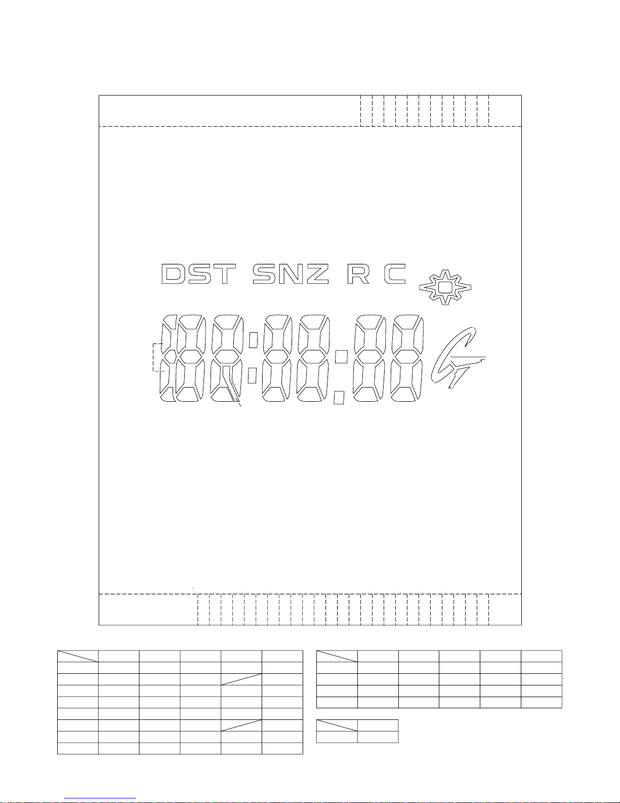
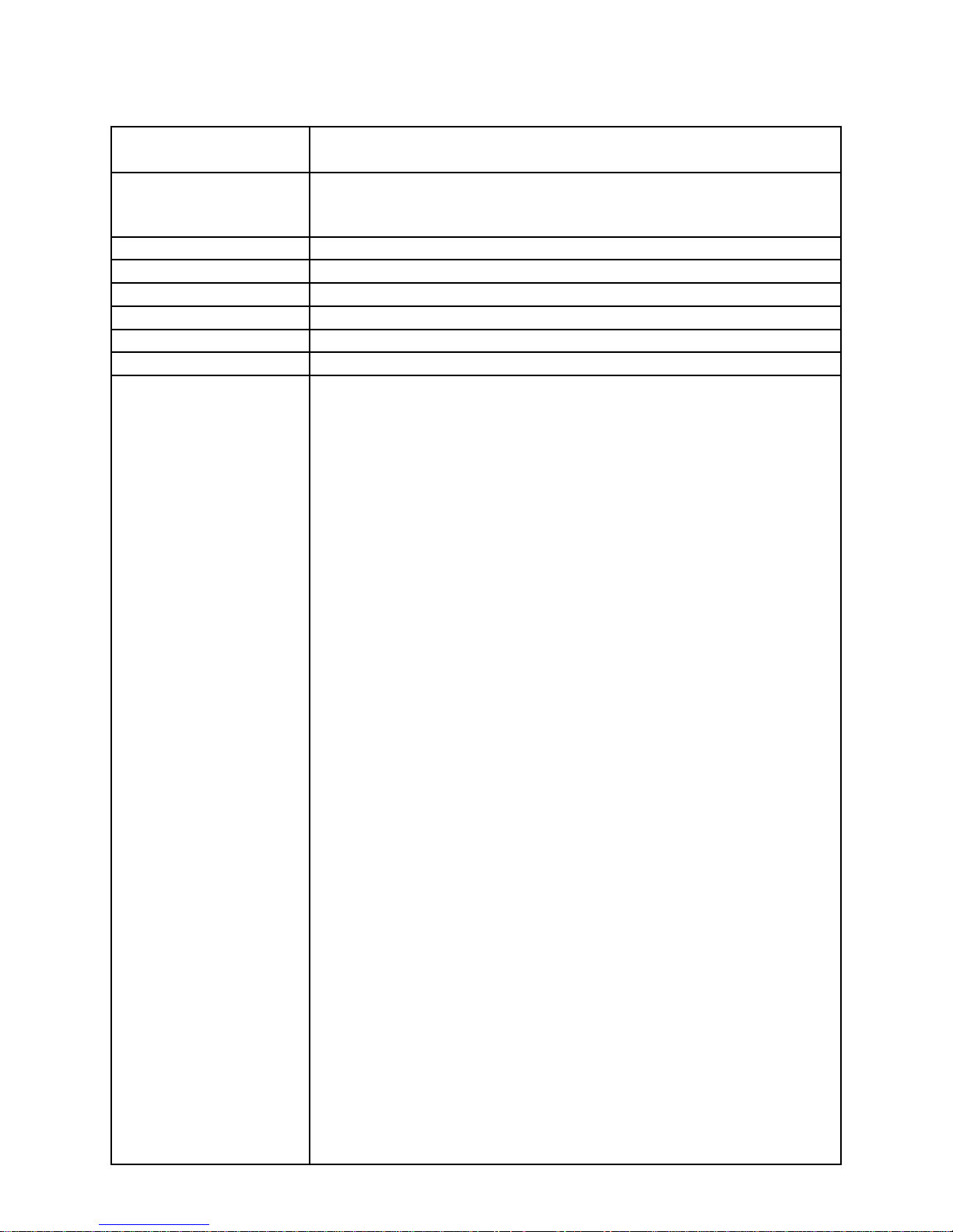
2. DRAWINGS: MODULE QW-4302
2-1. LCD DIAGRAM
L14
L13
L12
L11
dst
h5
a5
f5
i5
g5
k5
e5
j5
d5
b5
c5
a4
f4
g4
e4 c4
d4
col0
b4
col1
h4
snz
a3 a2
f3 f2
b3 b2
g3 g2 g1 g0
e3 e2
c3 c2
d3 d2 d1 d0
hyp0
point0
chargerecover
a1
f1 f0
b1 b0
e1 e0
c1 c0
a_light
a0
rc0
L10
rc2
L9
rc1
L15
SEG
L 9
L10
L11
L12
L13
L14
L15
L16
COM
rc2 k5 h5
d0
d3 g3
e2
d2
d4
LC2 LC3 LC4 LC5LC1
i5j5 dst
g5d5
c5
c3 b3
e3 b2
col1
a5
b5
a3
f3
col0
L16
L17
L18
a_light recover
snz
g0 a0
e0
g2
c2
point0 hyp0
f0
a2
f2
L19
— 2 —
L20
SEG
SEG
L17
L18
L19
L20
L29
L29
COM
COM
L30
LC3
LC2
LC1
LC2 LC3 LC4 LC5LC1
g4d1
rc1 e5 f5 c0 b0
L30
charge
LC5
LC4
f4 c1e4rc0
f1e1b4c4h4
a1g1a4
b1
Page 5

2-2. CHECKING TERMINALS AND COMPONENTS
Short pad for switching modules
KI6-GND: Short (Soldering)
KI8-GND: Open (No Soldering)
KI7-GND: Short (Soldering)
Kl3
SENSOR/TILT
VDD2
LED2
Kl1
L1
L5
GND
GND
KI5
L
R1
R1 VDD2
BD
R1
RPM
VDD2
GND
Kl7
L1LL3
GND
KC2
VPMRPM
GND
GND
Kl8
GND
Kl6
L
GND
R3
GND
R2
SHEET/INSHULASION 2763
GND
VDD1
R1
GND
N1 GND
N2
L1
L4
L18
L17
L16L6L15
VSC
GND
GND
CCP
GND
KI2
L9
L12
L11
L10
L14
L13
L1
L2
GND
XTB
XT
L7
L8
LC2
L20
L19
LC1
LC4
L29
L21
L22
L23
LC5
L30
LC3
L26
L24
L25
L27
L28
TAPE/ADHESIVE 1588
VDD2
LED1
OSCILLATOR/CRYSTAL
Kl4
Short pad for R trimming
KI2
Rxt3
Rxt2
Rxt2Rxt3
P4
GND
R
R
LED1
KI4
VSC
CAPACITOR/TRIMMER
3. PCB ASS'Y
Short pad for N trimming
(76409062)
VCC
VDD2
P9
GND
VCC
CCP
P2
P7
P7
GND
P7
P5
P5
XT
VDD2
VSC
KI9
KI9
AC
VDD2
GND
GND
VSC
VSC
SDO
FET-D
L1
L4
L2
L5
L3
P1
GND
VCH
GND
P2
FET-S
GND
LD1
GNDB
VDSP
VC2
VC1
VC4
L
VDSP
KI3
VHF
GND
VDD3GND
VC3
VDD2
LD1
SCIN
SCIN
GND
GND
VC1
GND
VCH
GND
VDD2
LED2
KI5
KI5
R
SCIN
R
GND
KI1
GND
SCR
GND
— 3 —
Page 6

3. EXPLODED VIEW: MODULE QW-4302
22 (10124956)
24 (10124960)
12 (10172632)
29 (72270343)
13 (10124962)
16 (10164777)
9 (10097687)
24 (10124960)
2 (10199933)
30 (72270294)
31 (10214214)
1 (76409146)
23 (10106509)
14 (10124963)
19 (72078349)
25 (10124961)
27 (10197474)
3 (76409062)
PCB Ass'y
21 (10123230)
8 (10022106)
26 (72019599)
7 (10016598)
17 (10172627)
25 (10124961)
28 (10169526)
4 (76408261)
10 (10182650)
11 (10172626)
20 (72078546)
21 (10123230)
6 (10168959)
18 (10181225)
15 (10106512)
5 (10065657)
Battery storage (CTL1616)
— 4 —
Page 7

4. PARTS LIST: MODULE QW-4302
-
s
p
p
(-)
QW-4302YC-01TK
1 QW-4302YC-01TK
Note: 1. Prices and specifications are subject to change without prior notice.
2. Spare parts are classified as follows according to their importance in after-sales service.
A Rank ---------------------------------------- Important
C Rank ---------------------------------------
3. Batteries in Bulk pack on the tray will be supplied from our Overseas Spare Parts Section under charge ba
Batteries in Blister pack will be supplied from our Sales Department.
4. As for order/supply of spare parts, refer to the separate publication "GUIDE BOOK for spare parts supply".
Attention to order
1The most of normal repair or initial repair within 1year since released month can be done by main parts.
2Minor parts should be ordered carefully in consideration of the actual usage of your repair and your technical skills.
3Main parts should be ordered and stocked appropriately in consideration of your parts usage anre repair usage for
similar models.
MAIN PARTS
Item Code No. Parts Name S
76409050 MODULE/WITH MOVEMENT QW-4302YC-01TK 1 A
1 76409146 ANALOG BLOCK QW-4302MV-82TK 1 A
2 10199933 LCD S4302-01TH 1 A
Not Important
ecification Q'TY R
1
3 76409062 PCB ASS'Y RJQ522137*002V01TK 1 A
MINOR PARTS
Item Code No. Parts Name S
4 76408261 ANTENNA ASS'Y RJQ522195*001V01TK 1 C
5 10065657 BATTERY/STORAGE CTL1616 1 C
6 10168959 CONTACT/BATTERY 2730 Q255819-2V05 1 C
7 10016598 CONTACT/BATTERY
8 10022106 CUSHION 2306-2 Q466886-1 1 C
9 10097687 CUSHION 2549 Q470646-1 1 C
10 10182650 CUSHION 3731 RJQ524044-001V01 1 C
11 10172626 HOLDER 3731 RJQ520563-001V01 1 C
12 10172632 HOLDER/ HOUR WHEEl 3731 RJQ520520-001V01 1 C
13 10124962 INTERCONNECTOR/ 2763-1 Q471264-1 1 C
14 10124963 INTERCONNECTOR/ 2763-2 Q471265-1 1 C
2348 Q366836-1 1 C
ecification Q'TY R
1
15 10106512 LABEL/ 2730 Q471007-1 1 C
16 10164777 LIGHT GUIDE Q373126-1V03 1 C
Notes: Q - Used quantity
R - Rank
A : Important
C: Not Important
— 5 —
Page 8

Item Code No. Parts Name Specification Q'TY R
p
1
17 10172627 PLATE/SHIELD 3731-1 RJQ520564-001V01 1 C
18 10181225 PLATE/SHIELD 3731-3 RJQ523783-001V01 1 C
19 72078349 SCREW Q47608A-1 2 C
20 72078546 SCREW/FLAT 355 Q411764-1 1 C
21 10123230 SCREW/FLAT2730 RJQ513792-001V01 4 C
22 10124956 SOLAR CELL BCS3028D6 1 C
23 10106509 SPRING/COIL 2730-1 Q470503-1 1 C
24 10124960 SPRING/COIL 2763-1 Q471262-1 2 C
25 10124961 SPRING/COIL 2763-2 Q471263-1 4 C
26 72019599 SPRING/COIL 967-1 Q430081-1 1 C
27 10197474 SPRING/LEAF Q373125-1V03 1 C
28 10169526 TAPE/ADHESIVE 3707 RJQ521248-001V01 1 C
29 72270343 WASHER 1325 Q450447-1 1 C
30 72270294 WASHER/745 Q436294A-1 1 C
31 10214214 WHEEL/HOUR 4302 RJQ528472-001V01 1 C
For the
rices and minimum order/supply quantities of the above parts, refer to the Parts Price List P.P.L.-636.
Notes: Q - Used quantity
R - Rank
A : Important
C: Not Important
— 6 —
Page 9

5. PRECAUTIONS FOR REPAIR: MODULE QW-4302
5-1. AC (ALL CLEAR) AND REMOVING OF MODULE
1. Perform AC (ALL CLEAR) when inserting a new battery, or else the memories and/ or counters may give
erratic displays.
Touch the AC contact and the main plate with the metallic tweezers.
The contact should be made for about two seconds.
2. On removing of the module from the case, please insert the precision screw driver between the module
and the case pointed by arrows.
Metallic tweezers
5-2. ACCURACY CHECKING
Check the accuracy of the module with the quartz timer after switching the module to “ACCURACY
CHECKING MODE”.
The operations are shown below:
A) SWITCHING TO “ACCURACY CHECKING MODE”
While pressing the B button, press A and C buttons at the normal timekeeping mode.
Then all the segments are displayed and the LCD drive signals are changed to the static drive signal
of “32 Hz” so that you can check the accuracy with the quartz timer.
B) CANCELLATION OF THE “ACCURACY CHECKING MODE”
Press any button.
Then the display is returned to its original state.
NOTE: The “ACCURACY CHECKING MODE” will
automatically return to the regular mode
in 1 ~ 2 hour(s) without any operation.
— 7 —
A
C
B
D
QW-4302
Page 10

5-3. SOLAR CELL-PCB ASS'Y CONTACT CHECKING
Check a Solar cell and PCB ass'y are contacted correctly by contact spring, when a module is
disassembled.
1. To enter TEST mode.
1) While pressing D button, press A and B buttons at the normal timekeeping mode.
2. Check a Solar cell and PCB ass'y contact in the following order.
1) Display side up and place the watch on the desk.
2) Check the display indicates as figure 2.
3) Display side down and place the watch on the desk more than two seconds.
Or go to a dark room and place the watch more than two seconds.
4) Check the display indicates as figure 3.
If "8888" is not appeared on the display, disassemble again the module and check the contact
spring between the Solar cell and PCB.
A
C
B
D
Figure 1 Figure 2
3. To exit from TEST mode
Press any button.
Press D, A and B buttons
Place the watch in a dark
room more than two seconds.
Appear "8888" on display.
Figure 3
— 8 —
Page 11

5-4. HOW TO CHECK TILT SENSOR
1) Press A, D and C buttons at the normal timekeeping mode.
2) Check the display indicates as figure 4.
3) Tilt the watch towards you more than 40 degrees.
4) Check the display indicates as figure 5.
Appear "TL" on display.
Tilt the watch towards you
more than 40°
Figure 4 Figure 5
5-5. TIME CALIBRATION SIGNAL TEST MODE
1) Press B, C and D button at the same time to enter the test mode.
2) Press A button to switch from one signal source to another.
J40: Fukushima, Japan (Call Sign: JJY, Frequency: 40kHz)
J60: Fukuoka/Saga, Japan (Call Sign: JJY, Frequency: 60kHz)
W60
: Fort Collins, Colorado (Call Sign: WWVB, Frequency: 60kHz)
3) Press B button to start signal reception.
Appear "8888" on display.
More than 40°
— 9 —
Page 12

6. TROUBLESHOOTING: MODULE QW-4302
This is a flow chart about signal reception.
START
Check whether the Home City
code is selected correctly.
To perform MANUAL time
calibration signal reception
Signal
reception OK?
No
To perform AUTO time
calibration signal reception
Signal
reception OK?
No
Replace the PCB ass'y
Signal
reception OK?
Yes
OK
Yes
OK
Yes
OK
No
Replace the Antenna ass'y
Signal
Yes
reception OK?
No
There is a possibility of location bad.
— 10 —
OK
Page 13

CASIO COMPUTER CO.,LTD.
Overseas Service Division
Shibuya-ku, Tokyo 151-8543, Japan
6-2, Hon-machi 1-Chome
 Loading...