

Page 1

S
ERVICE
M
ANUAL
& PARTS LIST
(WITHOUT PRICE)
QW-3195
MODULE NO.
REF. NO. S/M-1097
NOV. 2009
GW-2310
Page 2

CONTENTS
Page
1. SPECIFICATIONS: MODULE QW-3195 ................................................. 1
2. DRAWINGS: MODULE QW-3195 ........................................................... 2
2-1. LCD DIAGRAM ...........................................................................................2
2-2. CHECKING TERMINALS AND COMPONENTS ........................................3
3. EXPLODED VIEW: MODULE QW-3195 .................................................4
4. PARTS LIST: MODULE QW-3195 ..........................................................5
5. REPLACEMENT OF BATTERY: MODULE QW-3195 ............................ 6
6. DISASSEMBLY: MODULE QW-3195 ..................................................... 7
7. TESTING: MODULE QW-3195
7-1. MEASURING CURRENT CONSUMPTION ................................................7
7-2. ACCURACY CHECKING ............................................................................7
7-3. SOLAR CELL-PCB ASS'Y CONTACT CHECKING ..................................8
7-4. HOW TO CHECK TILT SENSOR ...............................................................8
7-5. TIME CALIBRATION SIGNAL TEST .........................................................9
Page 3
– 1 –
SPECIFICATIONS: MODULE QW-31951.
Item Detail
Battery CTL1616 (Storage battery)
Note: Use CTL1616 only. Other storage battery or CR1616 can cause
damage to the watch.
Battery life Approx. 10 months
Current consumption 1.22 µA maximum
See page 7
Alarm system Piezo plate on Cover/Back
Accuracy ±15 sec./month
Accuracy setting system Trimmer capacitor
Accuracy checking See page 7
Functions
• Shock resistant (G-SHOCK)
• Electro-luminescent backlight
Full auto EL light, afterglow
• Solar powered
World time
31 time zones (48 cities + coordinated universal time), city code display, daylight saving on/off
• 1/100-second stopwatch
Measuring capacity: 23:59’59.99”
Measuring modes: Elapsed time, split time, 1st-2nd place times
•
Countdown timer
Measuring unit: 1 second
Input range: 1 minutes to 24 hours (1-minute increments and 1-hour increments)
• Daily alarms
5 independent daily alarms (4 one-time alarms and 1 snooze alarm)
• Hourly time signal
• Battery power indicator
• Power Saving (turns off the display when the watch is left in the dark)
• Full auto-calendar (to year 2099)
• 12/24-hour format
• Button operation tone on/off
• Regular timekeeping: Hour, minute, second, pm, month, date, day
• Time Calibration Signal Reception
• Auto receive 6 times a day (Remaining auto receives cancelled as soon as
one issuccessful) (ve times for the China signal); Manual receive
Receivable Time Calibration Signals:
Mainingen, Germany (Call Sign: DCF77, Frequency: 77.5 kHz);
Anthorn, England (Call Sign: MSF, Frequency: 60.0 kHz);
Fort Collins, Colorado, the United States
(Call Sign: WWVB, Frequency: 60.0 kHz);
Fukushima, Japan (Call Sign: JJY, Frequency: 40.0 kHz);
Fukuoka/Saga, Japan (Call Sign: JJY, Frequency: 60.0 kHz);
Shangqiu City, Henan Province, China
(Call Sign: BPC, Frequency: 68.5 kHz)
Page 4
– 2 –
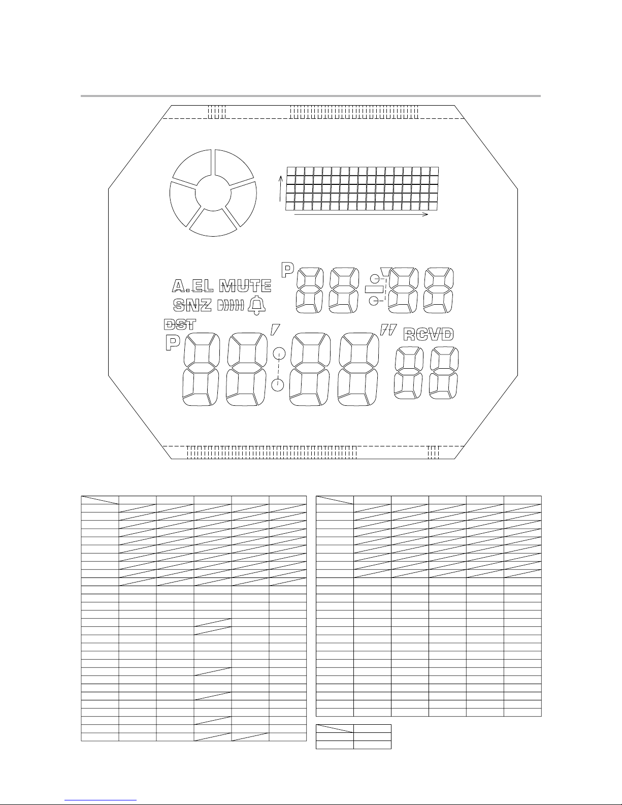
DRAWINGS: MODULE QW-31952.
LCD DIAGRAM2-1.
SNZ
AUTOEL
L37
L36
L35
L34
L33
L32
L31
L30
L29
L28
L27
L26
L25
L24
L23
L22
L21
L20
L19
L18
L17
L16
L15
L14
L13
L2
L1
MUTE
PSAVE
HIGH0
MID0
CHARGE
LOW0
x0
x16
y4
y0
hyp
a9
d9
g9
f9 b9
e9 c9
LC1
L54
L53
L56
L55
L58
L57
L60
L59
L62
L61
L64
L63
L66
L65
L68
L67
L69
LC5
LC5
LC2
LC3
DST
PM0
ALM
SIG
min
PM1
col1
sec
RC0
a8
d8
g8
f8 b8
e8 c8
a7
d7
g7
f7 b7
e7 c7
a6
d6
g6
f6 b6
e6 c6
h7
a5
d5
g5
f5 b5
e5 c5
a4
d4
g4
f4 b4
e4 c4
a3
d3
g3
f3 b3
e3 c3
a2
d2
g2
f2 b2
e2 c2
a1
d1
g1
f1 b1
e1 c1
a0
d0
g0
f0 b0
e0 c0
col0
COM
SEG
SEG
COM
x16y1
L 6
L 7
L 8
L 9
L10
L11
L12
L13
L14
L15
L16
L17
L18
L19
L20
L21
L22
L23
L25
L26
L24
L 5
L 4
L 3
L 37 L 36 L 35 L 2 L 1
L34
L32
L33
L27
L28
c 6
x16y0
b 6
d 0
x16y4
x16y3
c 0b 0
x16y2
x15y3
x15y1
x15y4
x15y0
x15y2
x14y3
x14y2
x14y0
x14y1
x14y4
x13y4
x13y1
x13y2
x13y0
x13y3
x12y2
x12y1
x12y0
x12y3
x12y4
x11y2
x11y1
x11y0
x11y3
x11y4
x10y1
x10y3
x10y4
x10y2
x10y0
x9y0
x9y4
x9y2
x9y3
x9y1
x8y1
x8y3
x8y2
x8y4
x8y0
x7y2
x7y4
x7y3
x7y1
x7y0
x6y1
x6y0
x6y4
x6y3
x6y2
x5y3
x5y1
x5y0
x5y4
x5y2
x4y3
x4y0
x4y4
x4y1
x4y2
x3y1
x3y2
x3y4
x3y3
x3y0
x2y2
x2y1
x2y0
x2y4
x2y3
x1y4
x1y2
x1y0
x1y1
x1y3
x0y2
x0y3
x0y0
x0y1
x0y4
L44
L45
L46
L47
L48
L49
L50
L51
L52
L53
L54
L55
L56
L57
L58
L59
L60
L61
L62
L63
L64
L65
L66
L67
L68
L69
CHAGE
a 0 g 0
d 6
e 0
g 6
f 6 e 6
d 1c 1f 0
RC0a 6
g 1
b 1 e 1
seca 7f 1a 1
c 7b 7b 2 c 2
g 2
a 2
g 7
d 2 d 7
c 3 e 7f 7f 2 e 2
h 7 col1d 3b 3
g 3
a 8 hype 3a 3 f 3
b 8col0min c 8
L31
L29
L30
f 4
a 4
b 4
c 5
g 4
c 4
e 4
d 4
b 9
f 8
g 8
c 9
e 8
d 8
LC1
SEG
COM
LC2 LC3 LC4 LC5
b 5
g 5
g 9
d 9
a 5 f 5 f 9 e 9
DST PM0 a 9 PM1
ALM SNZ MUTE SIG
LOW0MID0 HIGH0
d 5
e 5
AUTOEL
PSAVE
Page 5

– 3 –
CHECKING TERMINALS AND COMPONENTS2-2.
GND
VDD3
VDD1
KI6
KI3
KI2
KI1
KI4
VSC
GND
GND
KI10
KI7
KI8
VC2
VSC
SCIN
GND
VOUT
CRO
KI12
KI11
GND
GND
KI9
GND
GND
KI5 GND
GND
GND
VCH
VC4
VDSP
VHF GND
GND
GND
VC1
VSC
VC3
CRI
KI3GND
GND
GND
GND
KI2
CLF1
CLF2
WP
LL1
GND
XT
AC
XT
ANT_C3
KI3
KI6
KI1
ANT_C2
ANT1
ANT_C1
ANT2
LPF2QP
LPF2IN
PLL_C1
VR2OUT
GND
AGC
VDD
VDD2
RPL
PLL_C2
SHPR_C
LPF_BB
DET_C
PEAK_C
VCC
SCUT VDD2
VCC
VCC
GND
ANT1
KI4
GND
VDD2
GND
VDD2
VDD2
GND
XTB
VSC
VSC
VDD2
ANT2
LL1
VCH
VDSP
VC1
KI5
KI3
LL1
BD VDD2
LL1
GND
LL1
GND
L+ L-
GND
GND
GND GND
GND KI5
GND
ANT2
LPF2IP
GND
LPF2QN
VR1OUT
GND
Short pad for switching modules
KI11-GND: Open
KI12-GND: Open
Short pad for switching modules
KI7-GND: Open
KI8-GND: Open
KI10-GND: Open
OSCILLATOR/
CRYSTAL
CUSHION 3145-2
CUSHION 3145-1
CUSHION 3145-1
SENSOR/TILT
TAPE/ADHESIVE 2306
TRIMMER CAPACITOR
1. PCB ASS'Y
(00000000)
Page 6

– 4 –
EXPLODED VIEW: MODULE QW-31953.
6 (10300759)
7 (10323019)
10 (10321674)
2 (10332415)
8 (10323023)
14 (10054634)
5 (10168959)
1 (10330011)
8 (10323023)
3 (10323021)
13 (10080941)
11 (72300511)
PCB Ass'y
9 (10065664)
4 (10291127)
Battery Storage (CTL1616)
12 (72301036)
Page 7

4. PARTS LIST: MODULE QW-3195
Q
W-3195A
T
1QW-3195AT-01T
K
Note: 1. Prices and specifications are subject to change without prior notice.
2. S
p
are parts are classified as follows according to their importance in after-sales service.
A
Rank -----------------------------------------Important
C Rank ----------------------------------------
-
Not Important
3. Batteries in Bulk
p
ack on the tray will be supplied from our Overseas Spare Parts Section under charge basis.
Batteries in Blister
p
ack will be supplied from our Sales Department.
4. As for order/su
pply
of spare parts, refer to the separate publication "GUIDE BOOK for spare parts supply".
A
ttention to order
1. The most of normal re
p
air or initial repair within 1year since released month can be done by main parts.
2. Minor
p
arts should be ordered carefully in consideration of the actual usage of your repair and your technical skills.
3. Main
p
arts should be ordered and stocked appropriately in consideration of your parts usage anre repair usage for
similar models.
MAIN PARTS
Item Code No. Parts Name S
p
ecification Q'T
Y
R
1
10344144 MODULE/WITHOUT MOVEMEN
T
QW-3195AT-01TK 1
A
1 10330011 PCB ASS'
Y
RJQ546770*001V01TK 1
A
2 10332415 LCD K3195-01THP 1
A
MINOR PARTS
Item Code No. Parts Name S
p
ecification Q'T
Y
R
1
3 10323021 EL EL-3179-A-00 1 C
4 10291127 BATTERY/STORAG
E
CTL-1616W/CS 1 C
5 10168959 CONTACT/BATTERY 273
0
Q255819-2V05 1 C
6 10300759 CUSHION 3145-3 RJQ543393-001V01 1 C
7 10323019 CUSHION 3179 RJQ545767-001V01 1 C
8 10323023 INTERCONNECTOR 3179 RJQ545766-001V01 2 C
9 10065664 LABEL Q468543A-1 1 C
10 10321674 SPACER 3179-2 RJQ545765-001V01 1 C
11 72300511 SPRING/COIL 1253-2 Q439219-1 1 C
12 72301036 SPRING/COIL 1604-2 Q461742A-1 2 C
13 10080941 SPRING/COIL 2709-4 Q469735-1 2 C
14 10054634 TERMINAL/BATTERY
(-)
182
8
Q359948D-4 1 C
For the
p
rices and minimum order/supply quantities of the above parts, refer to the Parts Price List P.L.-672.
Notes: R - Rank
A: Im
p
ortant
C: Not Im
p
ortant
— 5 —
Page 8

– 6 –
REPLACEMENT OF BATTERY: MODULE QW-31955.
AC (ALL CLEAR)5-1.
Be sure to perform AC (All Clear) after batteries are replaced. Unless AC is performed, the memory
and/or counters may be displayed incorrectly.
Touch the AC contact and the main plate with the metallic tweezers.
The contact should be made for about two seconds.
SETTINGS AFTER AC5-2.
Function Settings Setting
Time Keeping Mode
(After AC)
■ Date: Saturday, January 1, 2005
■ Time: 12:00:00 AM
■ Home City Code: TYO
■ Home Time DST: AUTO
■ WT City Code DST/ Auto Receive
■ Home Time Auto Receive: ON
■ Time Format: 12-hour format
■ Power-saving: ON
■ Auto Light: OFF
■ Battery Level: HIGH
Factory default
World Time
■ WT City Code: UTC
■ Time Format: 12-hour format
■ DST: All Cities OFF
—
Alarm
■ Alarm Time: MA5 g 12:00 AM
■ Time: 12:00:00 AM
■ Home City Code: TYO
■ Home Time DST: AUTO
AL1 (Factory default)
Stopwatch —
24-hour range:
“Reset” setting (0’00’’00’’’00)
Countdown Timer
■ Indication: 0 hours 00 minutes
24-hour range:
“Reset” setting (0’00’’00’’’00)
Page 9

– 7 –
DISASSEMBLY: MODULE QW-31956.
When removing the back cover, do not misplace the spring/coil.
On removing of the module from the case, please insert the precision screw driver between the module and the case pointed by arrows.
SPRING/COIL 1604-2
SPRING/COIL 2709-4 SPRING/COIL 1253-2
TESTING: MODULE QW-31957.
MEASURING CURRENT CONSUMPTION7-1.
Measure the current value at 5 seconds after AC is performed.
* Measure within one minute while light is blocked from the watch face.
* Supply voltage is 2.5V.
ACCURACY CHECKING7-2.
Check the accuracy of the module with the quartz timer after switching the module to [ ACCURACY
CHECKING MODE ].
The operations are shown below:
SWITCHING TO [ ACCURACY CHECKING MODE ]1)
While pressing the A button, press D and C buttons at the normal time-
keeping mode.
Then all the segments are displayed and the LCD drive signals are
changed to the static drive signal of “32 Hz” so that you can check the accuracy with the quartz timer.
CANCELLATION OF THE [ ACCURACY CHECKING MODE ]2)
Press the D button.
Then the display is returned to its original state.
This mode will automatically return to the timekeeping mode in 1 ~ 2 hour(s) without any opera-
tion.
Time
keeping
mode
All lit
(1/5Duty)
Accuracy cheak
(1/4Duty)
Light
alternates
D
D
D
D
D
Home city
(TYO)
Module No. Indicator
(3179 000)
Home city change
NYC / LON / BER / HKG / TYO
B
D
B
A D+C
QW-3195
A
D
C
Page 10

– 8 –
SOLAR CELL-PCB ASS’Y CONTACT CHECKING7-3.
Check a Solar cell and PCB ass’y are contacted correctly by contact spring, when a module is disassembled.
To enter TEST mode.1)
1-1) While pressing A button, press D and B buttons at the normal timekeeping mode.
A B
A
→ D +
B
C D
Figure 1 Figure 2
L
SLR Bright
Check a Solar cell and PCB ass’y contact in the following order.2)
2-1) Check that “SLR” is displayed as shown in Figure 2, and place the watch in a sufciently-lit
area with its face up for 5 seconds.
2-2) Check that the display remains the same.
2-3) Place the watch on a desk with its glass face down for 5 seconds or more.Or go to a dark
area and leave the watch for 5 seconds or more.
2-4) Check that “8888” appears on the display indicating that light is insufcient.
Once “8888” appears, the display remains the
same even after the watch face is exposed to light.
Figure 3
To exit from TEST mode, press 3)
D
button.
HOW TO CHECK TILT SENSOR7-4.
While pressing 1)
A
button, press C and B buttons at the normal timekeeping mode.
Check the display indicates as gure 4.2)
Tilt the watch in the way that the “6-o’clock” end of the face is lowered. (45°)3)
How to tilt the watch: One tilting cycle is 0°(1 sec.) → 45°(1 sec.) → 0°. Repeat the cycle 3 times.
(Check the tilt sensor as described above at least twice).
Check the display indicates as gure 5.4)
Tilt the watch in the way that
the “6-o’clock” end of the face
is lowered.
(Repeat the cycle 3 times.)
Figure 4 Figure 5
To exit from TEST mode, press 5)
D
button.
Appear “8888” on display.
Appear “TLT” on display.
Appear “8888” on display.
(for more than two times)
Page 11

– 9 –
TIME CALIBRATION SIGNAL TEST7-5.
A signal reception failure may be caused by a number of of reasons.
Follow the steps shown in the owchart below to run the signal receiving test.
YES
YES
NO
NO
MANUAL Reception
Failure
OK
Reception OK?
Reception OK?
Check the Receiving Station
START
AUTO Reception
"Insufficient Signal" may also be the reason
for the signal receiving fault.
Insufcient Signal
The time calibration signal may not be properly received under the following conditions.
• The strength of the signal has changed due to season or time of day
• The watch is placed in the reinforced concrete building
• There is a broadcasting station nearby
• Strong enough signal cannot be received due to the position of the watch
The signal used for the local time setting differs from that for the facility testing in China using TEM cell.
* For the local time calibration signal, use the normal mode.
* To check the signal using TEM cell, perform the inspection in the Test Mode.
MANUAL/AUTO Reception7-5-1.
For details of MANUAL and AUTO reception modes, refer to the Operation Guide.
MANUAL Reception
While in Normal Time Keeping mode, hold down D for 2 seconds to start receiving signals manually.
Reception OK: The time is adjusted and “GET” appears on the display for 2 minutes.
Reception NG: No time adjustment is made and “ERR” appears on the display for 2 minutes.
* Press D to end the manual reception or the reception result display and return to the normal Time
Keeping Mode.
AUTO Reception
Turn on the AUTO Reception setting. When AUTO Reception is turned ON, the calibration signal is
automatically received up to 6 times from midnight through early morning.
(If reception is successful once, the subsequent AUTO reception will not be conducted on the same
day.)
Whether reception was successful may be conrmed with [Last Receiving Date/Time] in the [Last Reception] display.
(The date/time is updated after successful reception.)
Page 12

– 10 –
TEST MODE7-5-2.
While on the Timekeeping mode, hold down 1)
D
and press C and B at the same time to go to the
Time Calibration Signal Test mode.
Each time 2)
D
is pressed, the test signal receiving station changes as shown below:
JJY40 (J40) →JJY60 (J60) →WWVB (U60) →DCF77 (G77) →MSF (L60) →BPC1 (B01) →BPC2
(D02) →BPC3 (G03) →BPC4 (T04)
Press 3)
B
while in a receiving station state to start receiving a signal.
Pressing any button during reception results in a reception failure.4)
In approximately 7 minutes, check the indication and deterine the result by refering to the table 5)
below.
While on the Test mode, press 6)
C
or leave buttons untouched for 1 – 2 hours to leave the Test
mode and return to Timekeeping mode.
J40
J60
U60
G77
L60
D02
40kHz (JJY40)
60kHz (JJY60)
60kHz (WWVB)
77.5kHz (DCF)
60kHz (MSF)
the factory test in China (
BPC
)
BPC2
D02
BPC1
B01
BPC3
G03
BPC4
T04
JJY40
J40
JJY60
J60
WWVB
U60
DCF77
G77
MSF
L60
LCD
TYO
NYC
PAR,LON
HKG
D C+B
JJY40
JJY60
WWVB
DCF77
MSF
BPC1
BPC2
BPC3
BPC4
OK
J40 OK
J60 OK
U60 OK
G77 OK
L60 OK
B01 OK
D02 OK
G03 OK
T04 OK
NG
J40 NG
J60 NG
U60 NG
G77 NG
L60 NG
B01 NG
D02 NG
G03 NG
T04 NG
Indication of the Last Receiving Station
C
or
A.R
Selecting the Time Calibration Signal Receiving Station
To check in China, us BPC2.
D
D
D
D
B
D
D
D
D
D
D
Time keeping mode
Last Receiving SttnHome time city
Reception OK Reception NG
Reception result (Example;JJY40)
While signal reception
Reception Result
signal
reception
B
This part displays signal reception
status with L1 - L3.
L
C
A
D
B
Page 13

CASIO COMPUTER CO.,LTD.
Overseas Service Division
6-2, Hon-machi 1-Chome
Shibuya-ku, Tokyo 151-8543, Japan
 Loading...