

Page 1
SERVICE MANUAL
& PARTS LIST
REF. NO. S/M-976
NOV. 2006
MODULE NO.
QW-2983
BGT-2601JBGT-2600J
R
(WITHOUT PRICE)
Page 2

CONTENTS
Page
1. SPECIFICATIONS: MODULE QW-2983 .................................................... 1
2. DRAWINGS: MODULE QW-2983
2-1. LCD DIAGRAM ............................................................................................. 2
2-2. CHECKING TERMINALS AND COMPONENTS ..........................................3
3. EXPLODED VIEW: MODULE QW-2983 .................................................... 4
4. PARTS LIST: MODULE QW-2983 ............................................................. 5
5. PRECAUTIONS FOR REPAIR: MODULE QW-2983
5-1. AC (ALL CLEAR) AND REMOVING OF MODULE ...................................... 6
5-2. ACCURACY CHECKING ..............................................................................6
5-3. SOLAR CELL-PCB ASS'Y CONTACT CHECKING.....................................7
5-4. TIME CALIBRATION SIGNAL TEST MODE ................................................7
6. TROUBLESHOOTING FOR TIME RECEPTION:
MODULE QW-2983 .................................................................................... 8
Page 3
1. SPECIFICATIONS: MODULE QW-2983
Item Detail
Battery CTL1616 (Storage battery)
Note: Use CTL1616 only. Other storage battery or CR1616 can cause
damage to the watch.
Battery life Approx. 11 months
Current consumption 1.01 µA maximum
Alarm system Piezo plate on Cover/Back
Accuracy ±15 sec./month
Accuracy setting system Trimmer capacitor
Accuracy checking See page 6
Functions • Electro-luminescent backlight
Aferglow
• Solar powered
• Battery power indicator
• Power Saving (Turns off the display when the watch is left in the dark)
• Time calibration signal reception
Auto receive
Manual receive
Last date/time received display
• ReceivableTime Calibration Signals
Fort Collins, Colorado (Call Sign: WWVB, Frequency: 60kHz)
Fukushima, Japan (Call Sign: JJY, Frequency: 40kHz)
Fukuoka/Saga, Japan (Call Sign: JJY, Frequency: 60kHz)
• World Time
29 time zones (48 cities), daylight saving time on/off
• 1/100-sec.stopwatch
Measuring capacity: 59'59.99"
Measuring modes: Elapsed time, split time, 1st-2nd place times
• Daily alarms
5 independent daily alarms(4 one-time alarms and 1 snooze alarm)
• Hourly alarms
• Auto-calendar (to year 2039)
• 12/24-hr format
• Regular timekeeping:
hr, min, sec, pm, month, date, day
• Countdown timer
Measuring unit: 1/10 second
Countdown range: 60 minutes
Countdown start time setting range: 1 to 60 minutes (1-minutes increments)
— 1 —
Page 4
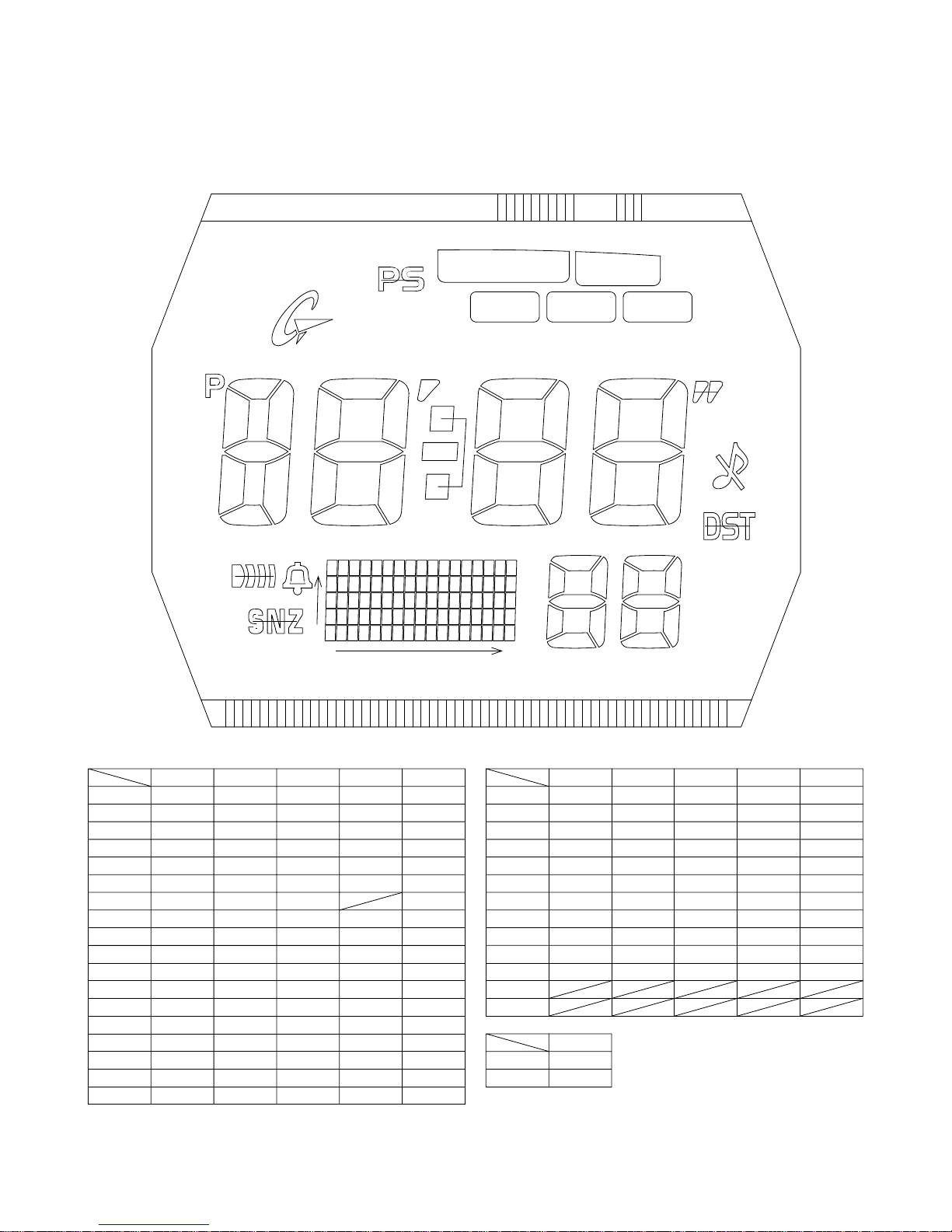
2. DRAWINGS: MODULE QW-2983
2-1. LCD DIAGRAM
LC1
LC4
LC5
L32
L31
LC3
LC2
PM
ALM
SNZ
anta0
f5
e5
d5
a5
g5
c5
PSAVE
anta1
anta2
a4
b5
f4
b4
g4
e4 e3
c4
d4
SIG
y4
y0
x0
min
hyp
col
RECOVER
a3
f3
g3
d3
x16
MID
b3
c3
a1
f1 b1
g1
e1
d1
CHARGE
a2
f2
g2
e2
d2
e0 c0
c1
HIGHLOW
sec
b2
MUTE
c2
DST
a0
b0f0
g0
d0
SEG
L 1
L 2
L 3
L 4
L 5
L 6
L 7
L 8
L 9
L10
L11
L12
L13
L14
L15
L16
L17
L18
L16
L17
L18
L19
L20
L21
L22
L23
L24
L25
L26
L27
L28
L29
L30
COM
LC1 LC2 LC3 LC4 LC5 LC2 LC3 LC4 LC5LC1
c1
g1
g2
e2
c3
g3
g4
e4
c5
g5
x16y2
x15y2
x14y2
x13y2
x12y2
x11y2
x10y2
x9y2 x9y1 x9y0 x9y4 x9y3
b1
f1
b2
f2
b3
f3
b4
f4
b5
f5
x16y1
x15y1
x14y1
x13y1
x12y1
x11y1
x10y1
MUTE
a1
sec
a2
a3
col hyp
min
a4
a5
PM
x16y0
x15y0
x14y0
x13y0
x12y0
x11y0
x10y0
LOW
RECOVER
anta0
anta1
anta2
SNZ
ALM
SIG
x16y4
x15y4
x14y4
x13y4
x12y4
x11y4
x10y4
d1
e1
c2
d2
d3
e3
c4
d4
d5
e5
x16y3
x15y3
x14y3
x13y3
x12y3
x11y3
x10y3
L13
L14
L15
COM
SEG
L19 x8y2
L20 x7y2
L21
L22
L23
L24
L25
L26
L27
L31
L32
L33
L34
COM
SEG
L28
L29
L12
L10
L11
x6y2
x5y2
x4y2
x3y2
x2y2
x1y2
x0y2
e0
g0
L30
CHARGE
PSAVE
L 1
L 2
L 3
L 4
L 5
L 6
L 7
L 8
L 9
x8y1
x7y1
x6y1
x5y1
x4y1
x3y1
x2y1
x1y1
x0y1
f0
b0
x8y0
x7y0
x6y0
x5y0
x4y0
x3y0
x2y0
x1y0
x0y0
DST
a0
x8y4
x7y4
x6y4
x5y4
x4y4
x3y4
x2y4
x1y4
x0y4
MID
HIGH
x8y3
x7y3
x6y3
x5y3
x4y3
x3y3
x2y3
x1y3
x0y3
d0
c0
— 2 —
Page 5

2-2. CHECKING TERMINALS AND COMPONENTS
Short pad for R trimming
Short pad for N trimming
KI1
R3
GND
GND R2
GND R1
VOUT
KI5
GND
GND
SCINSCR
SCIN
GND
SCIN
GND
GND
VSC
N2
GND
N1
GND
BD
L+
VCH
GND
VCH
KI8GND
VDSPGND
LL1
VDD3
VDSP
VC1VC2
VC1
2. PCB ASS'Y
(76409253)
VSC
L-
GND
VDD2
VDD1
GND
K18
CLF2
GND
VOUT
L-
L+
GND
VSC VDD2
CLF1
P1
FET-S
LL1 GND
P2
Rcp
GND
CLF2
CLF1
VDD2
LD1
GND
GNDB
GND
GND
FET-D P2
GND
VCC
GND
KI9
LL1
P13
KI7 GND
KI6
KI6
VCC
VDD2
P12
KI8 GND
VHF GND
P4
Rxt2
KI5
Short pad for switching modules
KI7-GND: Short (Soldering)
KC3
KC1
VC4R1VC3
GND
KI3KI4
GND
P14
Kl1
P9
P5
P5
Rcp
P7
Rxt3
Rxt3
P7
P7
KI6-KC3: Open (No Soldering)
KI6-KC1: Open (No Soldering)
XT
CAPACITOR/TRIMMER
KI3
XTB
XT
OSCILLATOR/CRYSTAL
CUSHION 466-A
TAPE/ADHESIVE 2306
K12
R1
AC
VDD2
VDD2
VSC
VDD2
LL1
Rxt2
Kl4
GND
VDD2
R1
— 3 —
Page 6

3. EXPLODED VIEW: MODULE QW-2983
1 (10207640)
9 (10209261)
6 (10209258)
14 (72301045)
2 (76409253)
PCB ass'y
8 (10209260)
12 (10209257)
13 (72301036)
7 (72311777)
11 (10123230)
5 (72311913)
15 (72019249)
3 (10065657)
Battery storage (CTL1616)
10 (10065664)
4 (10168959)
— 4 —
Page 7

4. PARTS LIST: MODULE QW-2983
p
p
-
p
s
pply
p
p
p
QW-2983AT-01TK
1 QW-2983AT-01TK
Note: 1. Prices and specifications are subject to change without prior notice.
are parts are classified as follows according to their importance in after-sales service.
2. S
A Rank ---------------------------------------- Im
C Rank ---------------------------------------
3. Batteries in Bulk
Batteries in Blister pack will be supplied from our Sales Department.
4. As for order/su
Attention to order
1The most of normal repair or initial repair within 1year since released month can be done by main parts.
2Minor parts should be ordered carefully in consideration of the actual usage of your repair and your technical skills.
3Main parts should be ordered and stocked appropriately in consideration of your parts usage anre repair usage for
similar models.
MAIN PARTS
Item Code No. Parts Name S
76409223 MODULE/WITHOUT MOVEMENT QW-2983AT-01TK 1 A
1 10207640 LCD K2983-01THP 1A
2 76409253 PCB ASS’Y RJQ527615*001V01TK 1 A
ack on the tray will be supplied from our Overseas Spare Parts Section under charge ba
of spare parts, refer to the separate publication "GUIDE BOOK for spare parts supply".
ortant
Not Important
ecification Q'TY R
1
MINOR PARTS
Item Code No. Parts Name S
3 10065657 BATTERY/STORAGE CTL1616 1 C
4 10168959 CONTACT/BATTERY 2730 Q255819-2V05 1 C
5 72311913 CONTACT/BATTERY(-) 1828 Q359948B-2 1 C
6 10209258 EL YEL-2983-A-60 1 C
7 72311777 HOLDER 1381 Q456843-1 1 C
8 10209260 INTERCONNECTOR 2983-1 RJQ526558-001V01 1 C
9 10209261 INTERCONNECTOR 2983-2 RJQ526559-001V01 1 C
10 10065664 LABEL/ 2368 Q468543A-1 1 C
11 10123230 SCREW/FLAT2730 RJQ513792-001V01 1 C
12 10209257 SPACER 2983-2 RJQ526556-001V01 1 C
13 72301036 SPRING/COIL 1604-2 Q461742A-1 2 C
14 72301045 SPRING/COIL 2017-1 Q462959-1 2 C
ecification Q'TY R
1
15 72019249 SPRING/COIL 675-3 Q413389A-1 1 C
For the
Notes: Q - Used quantity
rices and minimum order/supply quantities of the above parts, refer to the Parts Price List P.P.L.-636.
R - Rank
A : Important
C: Not Important
— 5 —
Page 8

5. PRECAUTIONS FOR REPAIR: MODULE QW-2983
5-1. AC (ALL CLEAR) AND REMOVING OF MODULE
1. Perform AC (ALL CLEAR) when inserting a new battery, or else the memories and/ or counters may give
erratic displays.
Touch the AC contact and the main plate with the metallic tweezers.
The contact should be made for about two seconds.
2. On removing of the module from the case, please insert the precision screw driver between the module
and the case pointed by arrows.
1
2
5-2. ACCURACY CHECKING
Check the accuracy of the module with the quartz timer after switching the module to “ACCURACY
CHECKING MODE”.
The operations are shown below:
A) SWITCHING TO “ACCURACY CHECKING MODE”
While pressing the A button, press C and D buttons at the normal timekeeping mode.
Then all the segments are displayed and the LCD drive signals are changed to the static drive signal
of “32 Hz” so that you can check the accuracy with the quartz timer.
B) CANCELLATION OF THE “ACCURACY CHECKING MODE”
Press any button.
Then the display is returned to its original state.
NOTE: The “ACCURACY CHECKING MODE” will
automatically return to the regular mode
in 1 ~ 2 hour(s) without any operation.
— 6 —
AB
CD
QW-2983
Page 9

5-3. SOLAR CELL-PCB ASS'Y CONTACT CHECKING
Check a Solar cell and PCB ass'y are contacted correctly by contact spring, when a module is
disassembled.
1. To enter TEST mode.
1) While pressing A button, press B and D buttons at the normal timekeeping mode.
2. Check a Solar cell and PCB ass'y contact in the following order.
1) Display side up and place the watch on the desk.
2) Check the display indicates as figure 2.
3) Display side down and place the watch on the desk more than 3 seconds.
Or go to a dark room and place the watch more than 3 seconds.
4) Check the display indicates as figure 3.
If “8888” is not appeared on the display, disassemble again the module and check the contact spring
between the Solar cell and PCB.
A
B
Press A, B and D buttons
C
D
Figure 1 Figure 2
Appear “8888” on display.
3. To exit from TEST mode
Press any button.
5-4. TIME CALIBRATION SIGNAL TEST MODE
1) Press B, C and D button at the same time to enter the test mode.
2) Press D button to switch from one signal source to another.
U60: Fort Collins, Colorado (Call Sign: WWVB, Frequency: 60kHz)
J40: Fukushima, Japan (Call Sign: JJY, Frequency: 40kHz)
J60: Fukuoka/Saga, Japan (Call Sign: JJY, Frequency: 60kHz)
3) Press B button to start signal reception.
Place the watch in a dark
room more than 3 seconds.
Figure 3
— 7 —
Page 10

6. TROUBLESHOOTING FOR TIME RECEPTION: MODULE QW-2983
START
Check whether the Home City
code is selected correctly.
Perform MANUAL time
calibration signal reception
Signal
reception OK?
No
Perform AUTO time
calibration signal reception
Signal
reception OK?
No
Replace the PCB ass'y
Signal
reception OK?
Yes
OK
Yes
OK
Yes
OK
There is a possibility of the bad location for reception.
No
Replace the Case center
ass'y with antenna
Signal
reception OK?
No
— 8 —
Yes
OK
Page 11

CASIO COMPUTER CO.,LTD.
Overseas Service Division
Shibuya-ku, Tokyo 151-8543, Japan
6-2, Hon-machi 1-Chome
 Loading...