

Page 1
SERVICE MANUAL
& PARTS LIST
REF. NO. S/M-843
FEB. 2004
MODULE NO.
QW-2634
STR-600
R
(WITHOUT PRICE)
Page 2

CONTENTS
Page
1. SPECIFICATIONS: MODULE QW-2634 .................................................... 1
2. OPERATION CHART: MODULE QW-2634 ............................................... 2
3. DRAWINGS: MODULE QW-2634
3-1. LCD DIAGRAMS ..........................................................................................7
3-2. CIRCUIT DIAGRAM ..................................................................................... 8
3-3. CHECKING TERMINALS AND COMPONENTS ......................................... 9
4. EXPLODED VIEW: MODULE QW-2634 ................................................... 10
5. PARTS LIST: MODULE QW-2634 ............................................................ 11
6. PRECAUTIONS FOR REPAIR: MODULE QW-2634
6-1. AC (ALL CLEAR) AND REMOVING OF MODULE ....................................12
6-2. ACCURACY CHECKING ............................................................................ 12
6-3. SOLAR CELL-PCB ASS'Y CONTACT CHECKING...................................13
6-4. HOW TO CHECK TILT SENSOR................................................................ 13
Page 3
1. SPECIFICATIONS: MODULE QW-2634
Item Detail
Battery CTL1616 (Storage battery)
Note: Use CTL1616 only. Other storage battery or CR1616 can cause
damage to the watch.
Battery life Approx. 10 months
Current consumption 1.19 µA maximum
Alarm system Piezo plate on Cover/Back
Accuracy ±15 sec./month
Accuracy setting system Trimmer capacitor
Accuracy checking See page 12
Functions: • Electro-luminescent backlight
Full auto EL light
• Solar powered
• Dual time
• Stopwatch: Time and distance measurements
Measuring unit: 1/100 second
Measuring capacity: Lap time (9:59'59.99") ; Split time (99:59'59.99")
Measuring modes: Elapsed time, lap/split times
Memory capacity: Up to 51 records (used by lap/split time records and log
title screens)
Others: lap/split number, Auto start (Automatically starts a Stopwatch Mode
elapsed time operation at a preset time); target split times (Watch beeps
when target time is reached and displays Target Split Differential); Leg
indicators
• Alarms
5 independent alarms (each can be set with daily alarm or weekly alarm)
• Hourly time signal
• Battery power indicator
• Power Saving: Turns off the display when the watch is left in the dark
• Auto-calendar: to year 2049
• 12/24-hour format
• Regular timekeeping: Hour, minutes, seconds, am/pm, month, date, day
— 1 —
Page 4
2. OPERATION CHART: MODULE QW-2634
SAVE
Getting Acquainted
Congratulations upon your selection of this CASIO watch. T o get the most out of your
purchase, be sure to carefully read this manual and keep it on hand for later reference
when necessary.
Expose the watch to bright light to charge its battery before using it.
You can use this watch even as its battery is being charged by exposure to bright
light.
Be sure to read “Battery” of this manual for important information you
•
need to know when exposing the watch to bright light.
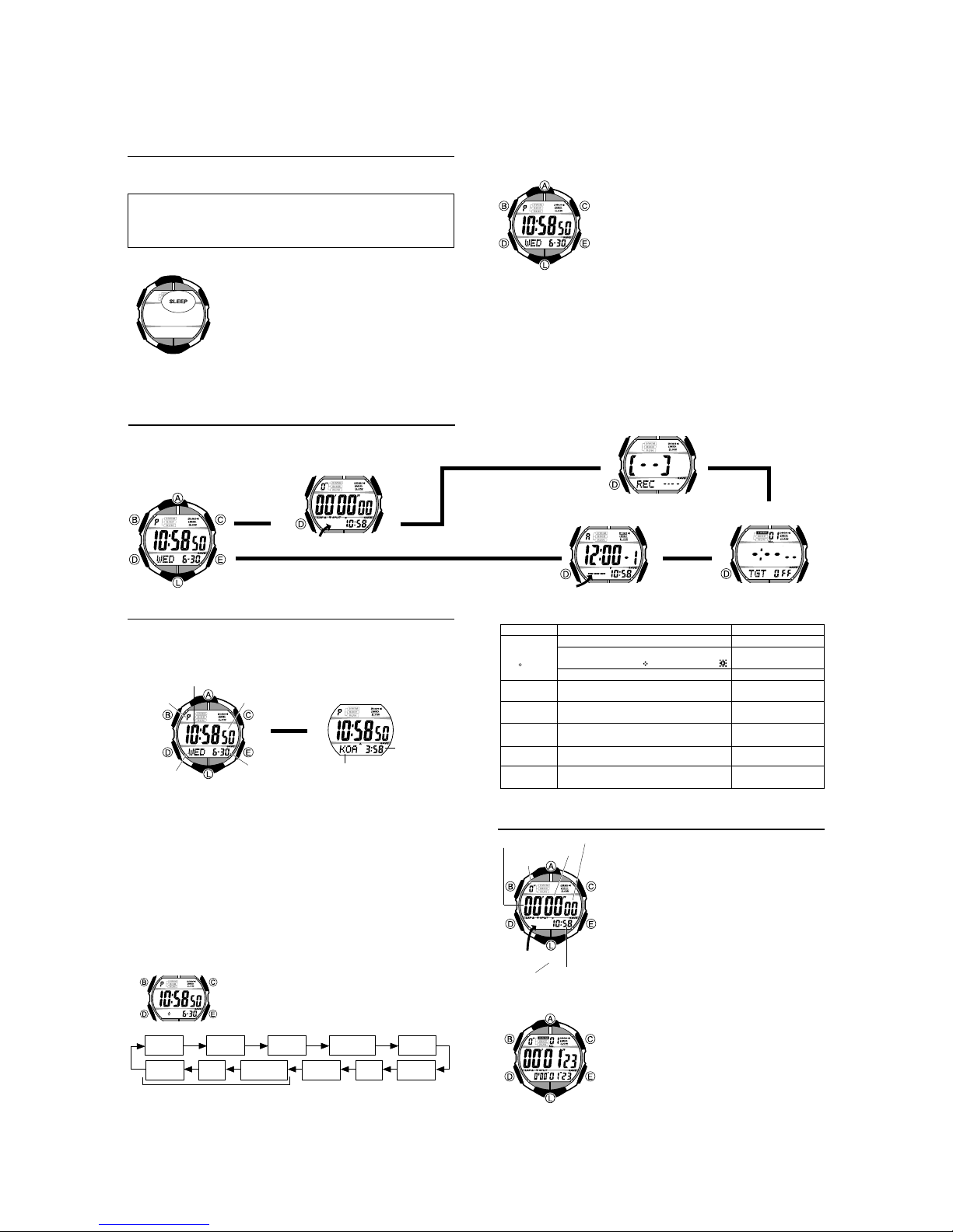
If the digital display of the watch is blank...
If the SLEEP indicator is on the display (either flashing or
steady), it means that the display is blank because the
watch’s Power Saving function has turned off the display
to conserve power.
Power Saving automatically turns off the display and
enters a sleep state whenever the watch is left for a
certain period where it is dark.
•
The initial factory default setting is Power Saving on.
•
The watch recovers from the sleep state if you move it to
a well-lit area
the watch towards your face for reading.
It can take up to two seconds for the display to turn
*
on.
•
See “Power Saving Function” for more information.
, if you press any button, or if you angle
*
About This Manual
(Light)
Button operations are indicated using the letters shown
•
in the illustration.
Each section of this manual provides you with the
•
information you need to perform operations in each
mode. Further details and technical information can be
found in the “Reference” section.
General Guide
D
•
Press to change from mode to mode.
•
In any mode (except for the Recall Mode), press to illuminate the display.
L
Stopwatch Mode
Timekeeping Mode
D
Press .
▲
F:50
STW
▲
Timekeeping
Use the Timekeeping Mode to set and view the current time and date. The
Timekeeping Mode also has a Dual Time screen that lets you view the current time in
Kona, Hawaii, which is the site of the Ironman Triathlon.
•
In the Timekeeping Mode, press to toggle between the Date and the Dual Time
screens.
PM indicator
Day of week
Setting the Time and Date
When setting the time, you can also configure settings for the display illumination
duration, the 12/24-hour format, power saving on/off, and the Dual Time screen.
About the Dual Time screen
The Dual Time screen is initially set up to show the time in Kona, Hawaii, which is the
site of the Ironman Triathlon. You can leave this setting the way it is or change it to
show the current time in another time zone.
•
If you need to adjust the current Kona time setting, use the “Time Differential Table”
for reference. If you live in T okyo for example, you would need to subtract 19 hours
from the current T okyo time to determine the current time in Kona, Hawaii. Note that
the times in the “Time Differential Table” are standard times. You need to subtract
one hour from these times during periods when summer time (Daylight Saving Time)
applies.
•
You can also use the Dual Time screen to keep track of the current time in another
area outside of the Kona, Hawaii time zone. If you do, you should turn off
(Kona time zone indicator) on the Dual Time screen. This will cause the indicator to
be replaced by an indicator that shows the day of the week for the current date.
Date
Hour : Minutes
To set the time and date
|
|
|
|
|
|
|
|
|
|
|
|
|
|
|
|
|
|
|
Seconds Hour Minutes
Hour DayMinutes
3. When the setting you want to change is flashing, use and to change it as
described below.
Dual time settings
C
Dual Time
Seconds
Press .
C
▲
▲
Dual time
mat
(Hour : Minutes)
KOA
B
Year
Month
Month – Day
1.In the Timekeeping Mode, hold down until the
seconds start to flash, which indicates the setting
screen.
2.Press to move the flashing in the sequence shown
D
below to select other settings.
KOA/Day of
the week
Kona time
zone indicator
Power
Saving
12/24-Hour
For
CE
▲
Alarm Mode
ALM
To do this:
Screen
P
10:58
12H
2004
KOA
KOA
4. Press to exit the setting screen.
Reset the seconds to
Toggle the display illumination duration setting
50
between 1.5 seconds ( ) and 2.5 seconds ( )
6-30
Change the hour or minutes
Toggle between 12-hour (
6-30
(
) timekeeping
24H
Change the year, month, or day
6-30
Toggle power saving on ( ) and off ( )
ON
Switch between the
3:58
DUAL
DUAL
___
and (day of the week)
Change the dual time hour or minutes
50
B
Stopwatch
The 1/100-second stopwatch measures elapsed time, as
well as lap/split times. The Stopwatch Mode also includes
a number of features and functions for the triathlete,
including lap/split time memory, auto-start, target splits,
leg (event) indicators, and more.
•
All of the operations in this section are performed in the
Stopwatch Mode, which you enter by pressing .
•
See “Timing a Triathlon” for information about triathlon
functions.
Measuring Elapsed Time
Use the following procedure to perform a basic elapsed
time operation with the stopwatch.
•
The stopwatch continues to run until you stop it. If the
elapsed time measurement reaches the maximum limit,
it will restart from zero.
1.In the Stopwatch Mode, press to start the elapsed
time measurement.
•
l
l
l
l
l
Starting an elapsed time operation displays the
elapsed time in the center of the display and in the
lower part of the display.
•
Note that pressing will not start an elapsed time
operation while an auto-start countdown is being
performed. In this case, you need to stop the autostart countdown before starting the elapsed time
operation.
•
Elapsed time measurement continues even if you exit
the Stopwatch Mode.
2.To stop elapsed time measurement, hold down for
about two seconds until the watch emits two short
beeps and then one long beep.
Hours
STW
Remaining
memory
1/100 second
Seconds
F:50
Timekeeping
Mode time
Minutes
To measure elapsed time
l
l
l
l
l
l
l
l
l
l
l
l
l
l
l
Recall Mode
▲
00
) and 24-hour
12H
ON OFF
(Kona) indicator
KOA
A
▲
Target Mode
Do this:
E
Press .
Press while the
C
seconds count is flashing.
Use (+) and (–).
EC
Press .
E
Use (+) and (–).
E
C
Press .
E
Press .
E
Use (+) and (–).
E
C
D
A
C
— 2 —
Page 5
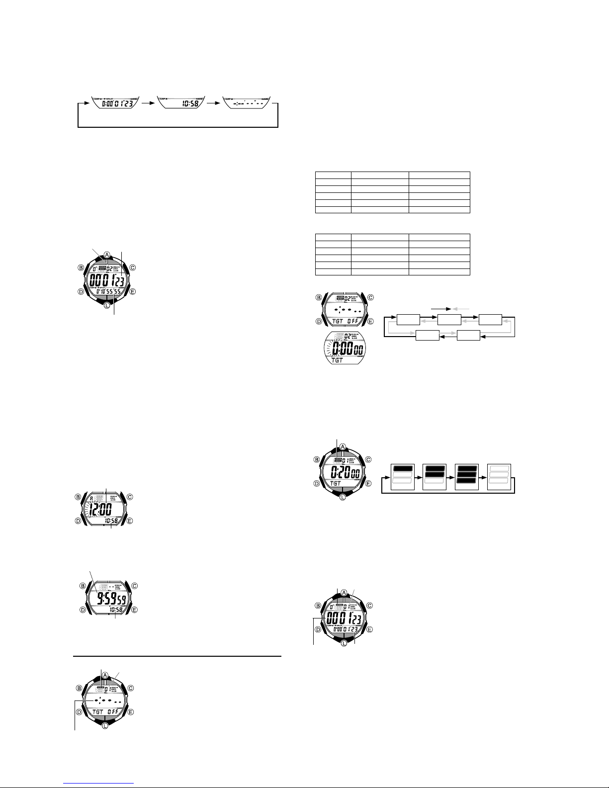
Pressing while an elapsed time operation is in progress or stopped cycles the
•
B
lower Stopwatch Mode display between the three screens shown below.
Split Time Timekeeping Target Split Differential
3. To clear the displayed stopwatch times to all zeroes, stop elapsed time
measurement and then hold down for two seconds until
the display and the watch beeps.
•
CC
Keep depressed until the watch beeps. If you release after
flash but the watch does not beep yet, the Stopwatch Mode measured times will
reappear.
Recording Lap and Split Times
“Lap time” is the time spent to cover a specific segment of a race, such as one lap
around a track.
“Split time” is the time spent from the beginning of a race up to a certain point.
•
The explanations in this section describe general lap and split time registration,
without using the target split feature for triathlon timing. They assume that all target
splits are turned off. See “Timing a Triathlon” for more information about target splits.
•
Lap/split times are stored in memory automatically whenever you perform a lap/split
time operation with the C button. See “Recall Mode” for more information.
To record lap/split times
Lap/Split number
Split time
4. To stop the elapsed time measurement, hold down for about two seconds, until
the watch emits two short beeps, followed by one long beep.
•
After stopping elapsed time measurement, you can resume it by pressing .
5. To clear the displayed stopwatch times to all zeroes, stop elapsed time
measurement and then hold down for two seconds until
the display and the watch beeps.
•
C
Keep depressed until the watch beeps. If you release after
flash but the watch does not beep yet, the Stopwatch Mode measured times will
reappear.
•
The lap/split number of the current lap/split flashes on the display while an elapsed
time measurement is in progress. Lap/split numbers are automatically incremented
starting from
maximum lap/split number is
number count to restart from
Auto-start
Auto-start automatically starts a stopwatch elapsed time operation when a time set by
you is reached.
Auto-start is coordinated with the current Timekeeping Mode time. The stopwatch
•
elapsed time operation will start automatically when the auto-start time you specify
is reached in the Timekeeping Mode.
Note that you can configure an auto-start time or turn auto-start on or off only while
•
the Stopwatch Mode screen shows all zeroes.
01
To set the auto-start time
Auto start time
Timekeeping
Mode time
To turn auto-start on and off
Time remaining untill
auto-start (hours,
minutes, seconds)
|
|
|
|
|
|
|
|
|
|
Timekeeping Mode time
Countdown Screen
B
Mode Time
C
1.In the Stopwatch Mode, press to start an elapsed
time measurement.
Lap time
2.Press to freeze the current lap time in the center of
C
the display and the current split time in the lower
display. The lap and split times are automatically stored
in memory at this time.
•
Pressing causes the watch to beep twice. The lap
C
time and split time will remain frozen on the display for
about eight seconds. After that, the display will
automatically change back to the elapsed time
display, which will show the time of the next lap in the
center and the total elapsed time (split time) at the
bottom.
•
Stopwatch timing continues internally while the lap/
split times are frozen on the display.
3.You can repeat step 2 as many times as you want.
CLR
stops flashing on
CLR
A
starts to
C
C
whenever you press in step 2 of the above procedure. The
|
|
|
|
|
|
C
99
. Recording a lap/split after that causes the lap/split
00
.
1.While the Stopwatch Mode screen shows all zeroes,
hold down until the hour setting of the auto-start
B
time starts to flash, which indicates the setting screen.
2.Press to move the flashing between the hour and
D
minute settings.
3.While a setting is flashing, use (+) and (–) to
change it.
4.Press to exit the setting screen.
B
While the Stopwatch Mode screen shows all zeroes, hold
E
down for about one second to toggle auto-start on
(countdown displayed) and off (all zeroes displayed).
•
When auto-start is turned on, the Stopwatch Mode
screen counts down the time remaining until the autostart time is reached. When the countdown reaches
zero, the watch beeps three times and a stopwatch
elapsed time operation starts automatically, regardless
of the mode the watch is currently in.
•
The auto-start countdown continues, even if you exit the
Stopwatch Mode.
•
Note that a stopwatch elapsed time operation cannot be
started manually by pressing while an auto-start
countdown is in progress. You need to turn of f auto-start
before using the stopwatch.
CLR
C
E
A
stops flashing on
CLR
starts to
C
A
Timing a Triathlon
You can configure the watch with up to five target split
Leg indicator
Lap/Split
times and leg indicators. Then when you time the legs of a
number
triathlon, the watch will display the leg indicators during
each leg, and beep when a preset target split time is
reached. You can even display the dif ference between a
preset target split time and your actual split.
•
See “Stopwatch” for full details about using the
Stopwatch Mode and for more information about lap and
split time operations.
Configuring the Watch for Triathlon T iming
You can use the Target Mode to configure the watch with target splits, and to display
leg indicators during timing of each leg.
Configuring the watch for timing a triathlon consists of the following three steps.
1 Setting target split times
2 Specifying leg indicators
3 T urning on the target splits you want to use
Target Splits and Leg Indicators
You can configure the watch up to five target lap/split times (
specify leg indicators (Swim, Bike, Run) that appear on the display on the Stopwatch
Mode screen during timing of each leg.
The following shows examples of two possible configurations that you can use.
through ) and
0501
Example 1: Swim: 20 minutes; Bike: 3 hours; Run: 2 hours
Leg Lap/Split Number Target Split
Swim
Bike
Run
None
None
Example 2: Swim: 20 minutes; Transition: 5 minutes; Bike: 3 hours; T ransition:
5 minutes; Run: 2 hours
Leg Split Number Target Split
Swim
Transition
Bike
Transition
Run
To configure target split times
•
If the hour setting does not flash when you hold down , it probably means that
a Stopwatch Mode elapsed time or auto-start countdown operation is being
performed. Go to the Stopwatch Mode and stop the operation.
D
3. Press to move the flashing between the hour, minute, and seconds settings.
4. While a setting is flashing, use (+) and (–) to change it.
•
You can specify a target split time of up to 99 hours, 59 minutes 50 seconds in
10-second steps.
5. Press to exit the setting screen.
B
To specify a leg indicator for a split
Leg indicator
To turn a target split on and off
1. In the Target Mode, use and to scroll through the target split screens (
05
through ) until the one you want to turn on or off is displayed.
2. Press to toggle the currently displayed target split on (target split time displayed)
B
and off (
:
x:xx xx
Timing During a Triathlon
Basically, timing a triathlon is the same as elapsed time measurement and lap/split
time recording in the Stopwatch Mode. The only difference is that you have the watch
configured with target splits and leg indicators before starting actual timing.
To time a triathlon
Leg indicator
Lap time
01
02
03
04
05
01
02
03
04
05
1.In the Target Mode, use and to scroll through the
target split screens (
whose time you want to set is displayed.
20 minutes
3 hours 20 minutes
5 hours 20 minutes
Off
Off
20 minutes
25 minutes
3 hours 25 minutes
3 hours 30 minutes
5 hours 30 minutes
through ) until the one
01
Press .
EC
01 02 03
2.After you select a target split, hold down until the
hour setting of the target split time starts to flash. This is
the setting screen.
B
CE
1.In the Target Mode, use and to scroll through the
target split screens (
whose leg indicator you want to specify is displayed.
2.Press to cycle through the leg indicator settings in
A
the sequence shown below to select the one you want.
SWIM
BIKE
RUN
(Swim)
through ) until the one
SWIM
BIKE
RUN
(Bike)
CE
displayed).
1.Use the procedure under “Configuring the Watch for
Lap/Split
number
Split time
Triathlon Timing” to configure the watch for triathlon
timing.
2.Use to enter the Stopwatch Mode.
D
3.When you start the first leg of a triathlon (usually the
swim leg), press to start an elapsed time
measurement.
If you have the watch configured to display leg
•
indicators, the leg indicator will flash on the display.
The current lap/split number will also be displayed.
4.When you reach the end of the first leg, press so the
watch beeps twice.
This will freeze the time of the first leg (lap/split
•
number
lower display. The times will also be stored
automatically in memory.
A
) in the center of the display and in the
01
CE
05
0405
CE
0501
SWIM
BIKE
RUN
(Run)
Press .
B
(None)
SWIM
BIKE
RUN
C
01
Target split (hours,
minutes, seconds)
— 3 —
Page 6

5. After about eight seconds, the display will automatically change back to the elapsed
time display, with the time of the current leg (lap) in the center and the total elapsed
time (split) at the bottom.
6. Repeat step 4 for each leg of the triathlon.
If you have the watch configured with targets for the transition periods (as in
•
Example 2), perform step 4 when you complete the transitions between legs.
7. When you complete the last leg of the triathlon, hold down for about two
seconds, until the watch emits two short beeps, followed by one long beep.
This stops the elapsed time measurement.
•
8. To clear the displayed leg (lap) time and total elapsed time to all zeroes, hold down
for two seconds until
C
Note
If you have a target split time set and turned on, the watch will beep for three
•
seconds when the split time being measured in the Stopwatch Mode during that split
reaches the target split time. You can also display the dif ference between your target
split time and the actual time you record for that split.
Pressing while an elapsed time operation is in progress or stopped cycles the
•
B
lower Stopwatch Mode display between the three screens shown below.
CLR
stops flashing on the display and the watch beeps.
C
B
Split Time
• All of the digits of the Target Split Differential contain dashes ( ) if the target split time
feature is turned off or if the current split time exceeds the preset target split time.
The target split time differential is displayed using hours, minutes, seconds and
1/100 second when it is less than 10 hours. Hours and minutes only are displayed
when the differential is 10 hours or greater.
Target time off
Target time exceeded
• Leg indicators can be displayed for up to five splits only. All leg indicators are
displayed if you record more than five lap/split times during an elapsed time
operation.
Timekeeping Mode Time
Less than 10 hours 10 hours or greater
Target Split Differential
Recall Mode
Log
number
Creation date
(Month – Day)
Log Title Screen
To recall stopwatch records
In the Recall Mode, use A (+) and L (–) to scroll through the log title screens, starting
from the newest one, as shown below. When the title screen of the log you want is
displayed, use E (+) and C (–) to cycle through the records contained in the log.
Oldest
Log Title
Next (New)
Log Title
• Stopwatch records are stored in “logs” that are created automatically by the watch.
See “Memory Management” for more information.
To delete a log
1. In the Recall Mode, display the Log Title screen of the log you want to delete.
2. Hold down B until the watch emits a beep and
• Press and hold B until
If you release B before
screen without deleting the log.
• Note that you cannot delete a log if the lap time currently displayed in the Stopwatch
Mode is part of that log. To delete the log, you first need to reset the Stopwatch
Mode screen to all zeroes.
Memory Management
Starting an elapsed time measurement operation in the Stopwatch Mode creates a
new log. Any lap/split times recorded during the elapsed time measurement, as well
as the final elapsed time are all stored in the records of the log. The log remains open
for data storage until you permanently close it by clearing the Stopwatch Mode screen
to all zeroes.
• The watch has enough memory to hold up to 51 records. Since each log title screen
uses up one record of memory space, the maximum number of lap/split time records
you can store depends on how many logs there are currently in memory, as shown
below.
• If watch memory is already full when you start a Stopwatch elapsed time
measurement operation that creates a new log, the oldest log in memory and all of
its records are deleted automatically to make room for the new log.
• If you are adding records to the only log in memory and watch memory becomes
full, adding another record causes the oldest record in the log to be deleted
automatically to make room for the new record.
L
▲
A
▲
▲
▲
A
Memory Capacity Number of Logs Lap/Split Time Record Capacity
51 records 2 51 records – 2 log title screens = 49
Use the Recall Mode to recall and delete records stored
by the Stopwatch Mode.
• The title screen of the newest log appears first whenever
you enter the Recall Mode.
• Log numbers are automatically assigned in sequence,
starting from
• xx is shown in place of the log number and creation
date on the Recall Mode screen if there are no
stopwatch records currently in memory.
• All of the operations in this section are performed in the
Recall Mode, which you enter by pressing D .
Newest
Log Title
▲
L
▲
CLR starts to flash on the display and then stops flashing.
CLR stops flashing the watch will return to the Log Title
Currently in Memory
01 .
Leg indicator
▲
Lap/Split number
▲
Lap time
Split time
CLR stops flashing on the display.
Press C .
▲
E
1 51 records – 1 log title screen = 50
5 51 records – 5 log title screens = 46
▲
▲
▲
— 4 —
Alarms
Alarm time
(Hour : Minutes)
AM indicator
ALM
Day of week
Timekeeping Mode time
Alarm Types
The alarm type is determined by the settings you configure, as described below.
• Daily alarm
Set the hour and minutes for the alarm time. This type of setting causes the alarm to
sound everyday at the time you set.
• Weekly alarm
Set the hour, minutes, and the day of the week for the alarm time. This type of setting
causes the alarm to sound every week at the time you set, on the day of the week you
set.
To set an alarm time
4. While a setting is flashing, use E (+) or (–) to change it.
• To set an alarm that does not include a day of the week (daily alarm), set
for the day of the week. Press E or CC until the mark appears (between
SUN and SAT) while the day of the week setting is flashing.
• When setting the alarm time using the 12-hour format, take care to set the time
correctly as a.m. (
5. Press B to exit the setting screen.
Alarm Operation
The alarm sounds at the preset time for about 10 seconds.
• To stop the alarm tone after it starts to sound, press any button.
• The alarm and the Hourly Time Signal operations are performed in all modes except
for the Timekeeping Mode setting screen.
To test the alarm
While in the Alarm Mode, hold down A to sound the alarm.
To turn an alarm and the Hourly Time Signal on and off
Alarm on indicator
You can set up to five independent alarms with hour,
minutes, and day of the week. When an alarm is turned
on, the alarm tone sounds when the alarm time is
reached.
You can also turn on an Hourly Time Signal, which will
cause the watch to beep twice every hour on the hour.
• The alarm number (
screen.
Time Signal screen is on the display.
• When you enter the Alarm Mode, the data you were
viewing when you last exited the mode appears first.
• All of the operations in this section are performed in the
Alarm Mode, which you enter by pressing D.
Alarm
number
1.In the Alarm Mode, use E and C to scroll through the
alarm screens until the one whose time you want to set
is displayed.
:00 x5
2.After you select an alarm, hold down B until the hour
setting of the alarm time starts to flash, which indicates
the setting screen.
• This operation automatically turns on the alarm.
3.Press D to move the flashing between the hour,
minute, and day of the week settings.
A indicator) or p.m. (P indicator).
1.In the Alarm Mode, use E and C to select an alarm or
the Hourly Time Signal.
2.Press B to toggle it on and off.
• Turning on an Alarm (
alarm on indicator on its Alarm Mode screen.
• In all modes, the alarm on indicator is shown for any
alarm that is currently turned on.
• The Hourly Time Signal on indicator is shown on the
display in all modes while the Hourly Time Signal is
turned on.
Hourly time signal on
indicator
1 through 5) indicates an alarm
:00 is shown for the alarm time when the Hourly
Press E. Press C .
x1 x2
___
x1 through x5) displays the
x3
x4
___
Backlight
Auto light switch
on indicator
The backlight uses an EL (electro-luminescent) panel that
causes the entire display to glow for easy reading in the
dark. The watch’s auto light switch automatically turns on
the backlight when you angle the watch towards your face.
• The auto light switch must be turned on (indicated by
the auto light switch on indicator) for it to operate.
• You can specify 1.5 seconds or 2.5 seconds as the
display illumination duration. See “To set the time and
date” for more information.
• See “Backlight Precautions” for other important
information about using the backlight.
To turn on the backlight manually
Press L in any mode (except for the Recall Mode) to
illuminate the display.
• The above operation turns on the backlight regardless of
the current auto light switch setting.
Page 7

About the Auto Light Switch
Turning on the auto light switch causes the backlight to turn on, whenever you position
your wrist as described below in any mode. Note that this watch features a “Full Auto
EL Light”, so the auto light switch operates only when available light is below a certain
level. It does not turn on the backlight under bright light.
Moving the watch to a position that is parallel to the ground and then tilting it
towards you more than 40 degrees causes the backlight to turn on.
Parallel to
ground
Warning!
• Always make sure you are in a safe place whenever you are reading the
display of the watch using the auto light switch. Be especially careful when
running or engaged in any other activity that can result in accident or injury.
Also take care that sudden illumination by the auto light switch does not
surprise or distract others around you.
• When you are wearing the watch, make sure that its auto light switch is turned
off before riding on a bicycle or operating a motorcycle or any other motor
vehicle. Sudden and unintended operation of the auto light switch can create a
distraction, which can result in a traffic accident and serious personal injury.
To turn the auto light switch on and off
In the Timekeeping Mode, hold down L for about two seconds to toggle the auto light
switch on (
• The auto light switch on indicator (
auto light switch is turned on.
displayed) or off ( not displayed).
) is on the display in all modes while the
More than
40°
Battery
This watch is equipped with a solar cell and a rechargeable battery (secondary
battery) that is charged by the electrical power produced by the solar cell. The
illustration shown nearby shows how you should position the watch for charging.
Example: Orient the watch so its face
is pointing at a light source.
• The illustration shows how to position
a watch with a resin band.
• Note that charging efficiency drops
when any part of the solar cell is
blocked by clothing, etc.
• Normally, you should try to keep the
watch outside of your sleeve as much
as possible. Charging is significantly
reduced if the face is only partially
covered.
Important!
• Storing the watch for long periods in an area where there is no light or wearing it in
such a way that it is blocked from exposure to light can cause rechargeable battery
power to run down. Be sure that the watch is normally exposed to bright light
whenever possible.
• This watch employs a solar cell that converts light into electricity, which charges a
built-in rechargeable battery. Normally, the rechargeable battery should not need
replacement, but after very long use over a number of years, the rechargeable
battery may lose its ability to achieve a full charge. If you experience problems
getting the rechargeable battery to a full charge, contact your dealer or CASIO
distributor about having the rechargeable battery replaced.
• The rechargeable battery should be replaced with a CASIO-specified CTL1616
battery only. Other rechargeable batteries can cause damage to the watch.
• All data stored in memory is deleted, and the current time and all other settings
return to their initial factory defaults whenever battery power drops to Level 4 and
when you have the battery replaced.
• Turn on the watch’s Power Saving function and keep it in an area normally exposed
to bright light when storing it for long periods. This helps to keep the rechargeable
battery from going dead.
Battery Power Indicator and RECOVER Indicator
The battery power indicator on the display shows you the current status of the
rechargeable battery’s power.
Level
Battery power
indicator
|
|
|
|
|
|
|
|
|
|
|
|
|
|
|
|
|
|
RECOVER
indicator
• The flashing CHARGE indicator at Level 3 tells you that battery power is very low,
and that exposure to bright light for charging is required as soon as possible.
• At Level 4, all functions are disabled and settings return to their initial factory
defaults. Functions are enabled once again after the rechargeable battery is
charged, but you need to set the time and date, after the battery reaches Level 3
from Level 4. You will not be able to set any of the other settings until the battery
reaches Level 2 after dropping to Level 4.
• Display indicators reappear as soon as the battery is charged from Level 4 to Level 3.
• Leaving the watch in direct sunlight or some other very strong light source can
cause the battery power indicator to temporarily show a reading that is higher than
the actual battery level. The correct battery power indicator should appear after a
few minutes.
• If you use the backlight or the alarm a number of times during a short period,
RECOVER appears on the display, and the backlight and beeper tone become
disabled until battery power recovers. After some time, battery power will recover
and RECOVER will disappear, indicating that the above functions are enabled again.
• If RECOVER appears frequently, it probably means that remaining battery power is
low. Leave the watch in bright light to allow it to charge.
1
|
|
|
|
|
|
2
|
|
|
3
4
Battery Power Indicator
|
|
|
|
|
|
|
|
|
|
|
|
|
|
|
|
|
|
|
|
|
|
|
|
(Charge Soon Alert)
Solar cell
Function Status
All functions enabled.
All functions enabled.
Except for timekeeping and
battery power indicator, all
functions and display indicators
are disabled.
All functions disabled.
Charging Precautions
Certain charging conditions can cause the watch to become very hot. Avoid leaving
the watch in the areas described below whenever charging its rechargeable battery.
Also note that allowing the watch to become very hot can cause its liquid crystal
display to black out. The appearance of the LCD should become normal again when
the watch returns to a lower temperature.
Warning!
Leaving the watch in bright light to charge its rechargeable battery can cause it
to become quite hot. Take care when handling the watch to avoid burn injury.
The watch can become particularly hot when exposed to the following
conditions for long periods.
• On the dashboard of a car parked in direct sunlight
• Too close to an incandescent lamp
• Under direct sunlight
Charging Guide
After a full charge, timekeeping remains enabled for up to about 10 months.
• The following table shows the amount of time the watch needs to be exposed to light
each day in order to generate enough power for normal daily operations.
Exposure Level (Brightness)
Outdoor Sunlight (50,000 lux) 5 minutes
Sunlight Through a Window (10,000 lux) 24 minutes
Daylight Through a Window on a Cloudy Day (5,000 lux) 48 minutes
Indoor Fluorescent Lighting (500 lux) 8 hours
• Since these are the specs, we can include all the technical details.
• Watch is not exposed to light
• Internal timekeeping
• Display on 18 hours per day, sleep state 6 hours per day
• 1 backlight operation (1.5 seconds) per day
• 10 seconds of alarm operation per day
• Stable operation is promoted by frequent charging.
Recovery Times
The table below shows the amount exposure that is required to take the battery from
one level to the next.
Exposure Level
(Brightness)
Outdoor Sunlight
(50,000 lux)
Sunlight Through a
Window (10,000 lux)
Daylight Through a
Window on a Cloudy
Day (5,000 lux)
Indoor Fluorescent
Lighting (500 lux)
• The above exposure time values are all for reference only. Actual required exposure
times depend on lighting conditions.
Approximate Exposure Time
Level 4 Level 3 Level 2 Level 1
2 hours 21 hours 6 hours
6 hours 108 hours 30 hours
9 hours 219 hours 60 hours
103 hours ------------ ------------
Approximate
Exposure Time
▲
▲
Reference
This section contains more detailed and technical information about watch operation.
It also contains important precautions and notes about the various features and
functions of this watch.
Timekeeping
• Resetting the seconds to 00 while the current count is in the range of 30 to 59
causes the minutes to be increased by 1. In the range of 00 to 29, the seconds are
reset to
00
• With the 12-hour format, the
• With the 24-hour format, times are displayed in the range of 0:00 to 23:59, without
• The 12-hour/24-hour timekeeping format you select in the Timekeeping Mode is also
• The year can be set in the range of 2000 to 2049. The day of the week is calculated
• The watch’s built-in full automatic calendar automatically makes allowances for
Auto Return Features
If you leave a screen with flashing digits on the display for two or three minutes without
performing any operation, the watch automatically exits the setting screen.
Scrolling
The A, C, E , and L buttons are used in various modes and setting screens to
scroll through data on the display. In most cases, holding down these buttons during a
scroll operation scrolls through the data at high speed.
Power Saving Function
When turned on, the Power Saving function automatically puts the watch into a sleep
state whenever it is left for a certain period in an area where it is dark. The table below
shows how watch functions are affected by the Power Saving function.
• Wearing the watch inside the sleeve of clothing can cause it to enter the sleep state.
• The watch will not enter the sleep state while the Timekeeping Mode time is
• The watch will not enter the sleep state while it is in the Stopwatch Mode.
without changing the minutes.
range of noon to 11:59 p.m. and the
of midnight to 11:59 a.m.
any indicator.
applied in all other modes.
automatically in accordance with the date you set.
different month lengths and leap years. Once you set the date, there should be no
reason to change it except when battery power drops to Level 4.
Elapsed Time
in Dark
60 to 70 minutes
6 or 7 days
between 6:00 AM and 9:59 PM. If the watch is already in the sleep state when the
time reaches 6:00 AM, however, it will remain in the sleep state.
P
(PM) indicator appears on the display for times in the
Display
Blank, with
SLEEP flashing
Blank, with
SLEEP not flashing
A
(AM) indicator appears for times in the range
Operation
Display is off, but all functions are enabled.
All functions are disabled, but timekeeping
is maintained.
▲
— 5 —
Page 8

To recover from the sleep state
Perform any one of the following operations.
• Move the watch to a well-lit area. It can take up to two seconds for the display to turn
on.
• Press any button.
• Angle the watch towards your face for reading.
To turn Power Saving on and off
Backlight Precautions
• The electro-luminescent panel that provides illumination loses power after very long
use.
• The illumination provided by the backlight may be hard to see when viewed under
direct sunlight.
• The backlight automatically turns off whenever an alarm sounds.
• The watch may emit an audible sound whenever the display is illuminated. This is
due to vibration of the EL panel used for illumination, and does not indicate
malfunction.
• Frequent use of the backlight runs down the battery.
Auto light switch precautions
• Wearing the watch on the inside of your wrist, movement of your arm, or vibration of
your arm can cause frequent activation of the auto light switch and illumination of the
display. To avoid running down the battery, turn off the auto light switch whenever
engaging in activities that might cause frequent illumination of the display.
• Note that wearing the watch under your sleeve while the auto light switch is turned
on can cause frequent illumination of the display and can run down the battery.
More than 15 degrees
too high
• Static electricity or magnetic force can interfere with proper operation of the auto
light switch. If the backlight does not light, try moving the watch back to the starting
position (parallel with the ground) and then tilt it back towards you again. If this does
not work, drop your arm all the way down so it hangs at your side, and then bring it
back up again.
• Under certain conditions, the backlight may not light until about one second after you
turn the face of the watch towards you. This does not necessarily indicate
malfunction of the backlight.
• You may notice a very faint clicking sound coming from the watch when it is shaken
back and forth. This sound is caused by mechanical operation of the auto light
switch, and does not indicate a problem with the watch.
1.In the Timekeeping Mode, hold down B until the
seconds start to flash, which indicates the setting
screen.
|
|
|
|
|
|
|
|
|
|
2.Press D seven times until the Power Saving on/off
|
|
|
|
|
|
|
|
|
|
|
|
|
|
|
|
|
screen appears.
|
|
|
|
3.Press E to toggle Power Saving on (
|
|
|
OFF
).
(
4.Press B to exit the setting screen.
• The Power Saving on indicator (SAVE) is on the display
in all modes while the Power Saving is turned on.
• The backlight may not light if the face of the watch is
more than 15 degrees above or below parallel. Make
sure that the back of your hand is parallel to the ground.
• The backlight turns off after the preset display
illumination duration (see “To set the time and date”),
even if you keep the watch pointed towards your face.
ON
) and off
Time Differential Table
Pago Pago +01.0 –11.0
Cities in Zone
Honolulu, Papeete +00.0 –10.0
Anchorage, Nome –01.0 –09.0
Los Angeles, San Francisco, Las Vegas, Vancouver,
Seattle/Tacoma, Dawson City
Denver, El Paso, Edmonton –03.0 –07.0
Chicago, Houston, Dallas/Ft. Worth, New Orleans,
Mexico City, Winnipeg
New York, Montreal, Detroit, Miami, Boston, Panama City,
Havana, Lima, Bogota
Caracas, La Paz, Santiago, Pt. Of Spain –06.0 –04.0
Rio De Janeiro, Sao Paulo, Buenos Aires, Brasilia,
Montevideo
Praia –09.0 –01.0
London, Dublin, Lisbon, Casablanca, Dakar, Abidjan –10.0 +00.0
Paris, Milan, Rome, Madrid, Amsterdam, Algiers, Hamburg,
Frankfurt, Vienna, Stockholm, Berlin
Cairo, Jerusalem, Athens, Helsinki, Istanbul, Beirut,
Damascus, Cape Town
Jeddah, Kuwait, Riyadh, Aden, Addis Ababa, Nairobi,
Moscow
Tehran, Shiraz –13.5 +03.5
Dubai, Abu Dhabi, Muscat –14.0 +04.0
Kabul –14.5 +04.5
Karachi, Male –15.0 +05.0
Delhi, Mumbai, Kolkata –15.5 +05.5
Dhaka, Colombo –16.0 +06.0
Yangon –16.5 +06.5
Bangkok, Jakarta, Phnom Penh, Hanoi, Vientiane –17.0 +07.0
Hong Kong, Singapore, Kuala Lumpur, Beijing, Taipei,
Manila, Perth, Ulaanbaatar
Tokyo, Seoul, Pyongyang –19.0 +09.0
Adelaide, Darwin –19.5 +09.5
Sydney, Melbourne, Guam, Rabaul –20.0 +10.0
Noumea, Pt. Vila –21.0 +11.0
Wellington, Christchurch, Nadi, Nauru Is. –22.0 +12.0
* Based on data as of June 2003.
Difference Between
Local Time and Kona Time
–02.0 –08.0
–04.0 –06.0
–05.0 –05.0
–07.0 –03.0
–08.0 –02.0
–11.0 +01.0
–12.0 +02.0
–13.0 +03.0
–18.0 +08.0
Differential
GMT
— 6 —
Page 9

3. DRAWINGS: MODULE QW-2634
3-1. LCD DIAGRAMS
LC3
L31
L32
L33
L34
L35
LC1
e6
LC2
COL1
a6
b6
f6
g6
c6
d6
L36
L37
SWIM
BIKE
RUN
L38
L39
L40
L41
L42
e12
L43
L44
a12
f12
b12
g12
c12
d12
NO
L47
a11
f11
g11
e11
d11
b11
c11
SLEEP
L50
L51
L52
HIGH
MID
LOW
L53
L54
L55
LC4
LC5
SEG
L 1
L 2
L 3
L 4
L 5
L 6
L 7
L 8
L 9
L10
L11
L12
L13
L14
L15
L16
L17
L18
L19
L20
L21
L22
L23
L24
L25
L26
L27
L31
a5
f5 b5
g5
e5 c5
d5
a4
f4 b4
g4
e4 c4
d4
Y4
Y0
X0
L30
L29
L28
COM
LC1 LC2 LC3 LC4 LC5
X14Y2
X13Y2
X12Y2
X11Y2
X10Y2
X9Y2
X8Y2
X7Y2
X6Y2
X5Y2
X4Y2
X3Y2
X2Y2
X1Y2
X0Y2
X15Y2
X16Y2
g12
c12
g11
c11
c6
g6
X14Y1
X13Y1
X12Y1
X11Y1
X10Y1
X9Y1
X8Y1
X7Y1
X6Y1
X5Y1
X4Y1
X3Y1
X2Y1
X1Y1
X0Y1
X15Y1
X16Y1
e12
d12
e11
d11
d6
e6
X14Y0
X13Y0
X12Y0
X11Y0
X10Y0
X9Y0
X8Y0
X7Y0
X6Y0
X5Y0
X4Y0
X3Y0
X2Y0
X1Y0
X0Y0
X15Y0
X16Y0
SWIM
BIKE
RUN
NO
MID
HIGH
L25
L24
X14Y4
X13Y4
X12Y4
X11Y4
X10Y4
X9Y4
X8Y4
X7Y4
X6Y4
X5Y4
X4Y4
X3Y4
X2Y4
X1Y4
X0Y4
X15Y4
X16Y4
COL1
f5
MINSEC
a3
f3 b3
a2
f2
b2
COL3
e2
g2
c2
g3
e3 c3
COL0
d3
SPLITLAP SAVERECOV
PM1
AM1
a10
h10
f10
g10
e10
i10
d10
d2
MIN1
a9
b10
f9
b9
g9
HYP1
c10
e9
c9
COL2
d9
X16
L23
L22
L21
L20
L17
L16
L15
L14
L13
L12
L11
L10
L 9
COM
X14Y3
X13Y3
X12Y3
X11Y3
X10Y3
X9Y3
X8Y3
X7Y3
X6Y3
X5Y3
X4Y3
X3Y3
X2Y3
X1Y3
X0Y3
X15Y3
X16Y3
SEG
L32
L33
L34
L35
L36
L37
L38
L39
L40
L41
L42
L43
L44
L45
L46
L47
L48
LC1 LC2 LC3 LC4 LC5
b5
e4
g4
e3
g3
f0
g0
g1
e1
g2
e2
f8
g8
L49
COM
f7
g7
b9
f9
b10
g10
L30
SLEEP
LOW
a12
a11
a6
e5
f12
b12
f11
b11
b6
f6
g5
L50
L51
L52
L53
L54
L55
SEG
L28
L29
MIN0
f8a8b8
e8
d8
L 8
L 7
a5
f4
b4
COL3
f3
b3
a0
b0
b1
f1
b2
f2
e8
c8
e7
c7
g9
e9
c10
e10
ALM
SIG
AUTOEL
a1
b1
f1
g1
c1
e1
d1
f7
g8
g7
e7
c8
d7
L 6
L 5
L 4
a4
MINSEC
a0
b0
f0
g0
c0
e0
d0
a7
b7
c7
L 3
L 2
L 1
d5
c5
d4
LAP
c4
COL0
a3
SIG
AUTOEL
ALM
a1
MIN0
a2
d8
SPLIT
d0
MIN1
d3
c3
e0
c0
c1
d1
c2
d2
a8
b8
d7
c9
d9
d10
i10
RECOV
SAVE
HYP1
PM1
AM1
h10
a7
b7
COL2
a9
a10
f10
— 7 —
Page 10

3-2. CIRCUIT DIAGRAM
LCD (2.8V 1/3b 1/5d)
AC
T1
T2
T3
T4
S2
KI1
S1
KI2
S5
KI3
S3
KI4
SA
KI5
S4
KI6
SB
KI7
KI8
SK
✽5
✽7
✽7
✽4
✽4
✽4
Xtal
CT
✽3
KI9
N1
✽3
N2
✽3
R1
✽3
R2
✽3
✽3
R3
XTB
XT
LD1
C9
L1 - - - - L55 LC1 - - - LC5 SDO SCK CSBSDI
✽8
LSI
TOTAL 106PINS
BONDING 101PINS
GND VDD2 VCH VDD3 VC1 VC2VDD1BD VDSPVC3 VC4 VHFVSC
R1
BAT
Di2
Tr1
PZ
Z
LL1
C7
Di1
SC
C8
✽1✽1 ✽1✽1
SCR
SCIN
VPM✽1
KC1
KC2
✽9
KC3
✽10
KC4
C2C5 C1C4C6
C3
RP1RP2
Cp
✽2
✽2
✽2
Rb
GNDB
GND
BACK
EL
✽6
FRONT
LL2
L–
VOUT
L+
E'
CLF2
CLF1
V+
INV
✽ 1. No bonding
Cel
✽ 2. Soldering pads (for switching modules) are not used in
this module, and are all open.
✽ 3. Latch type key
✽ 4. Short (Soldering) (R trimming)
✽ 5. Inclination sensor
✽ 6. GNDB is used for the bias on the back of the tip.
✽ 7. Short (Soldering) (N trimming)
✽ 8. L28~L30 are used as the static drive pins.
✽ 9. KC2 is used in this module.
✽ 10. KC3 is used in this module.
— 8 —
Page 11

3-3. CHECKING TERMINALS AND COMPONENTS
Capacitor/Chip
C5
Capacitor/Chip
C8
Capacitor/Chip
C9
Capacitor/Chip
Cp
Capacitor/Chip
C6
C4
Capacitor/Chip
Capacitor/Chip
C3
C7
Capacitor/Chip
Resistor/Chip
RP1
Capacitor/Chip
Cel
LL2
Coil
INV
SK
13. Sensor/Tilt
(7105 5275)
Inverter
Resistor/Chip
RP2
KI7
GND
VSC
VOUT
KI8
KC4
KC3
GND
GND
GND
GND
GND
GND KI9
KI8
KI8
KC2
R3
R2
R1
N2
N1
3. PCB ASS'Y
(7640 7246)
KI5
KI1
KI4
KI4
GND
KI6
KI3
KI2
KI6
GND
GND
GND VDD3
KI3
KI2
GND VCH
VC3 VC4
VC2
XTB
VC1
VDSP
VHF
VDD1GND
GND
XT
XT
VDD2GND
GND
VCH
VC1
VDSP
AC
VDD2
KI7
CLF1
VSC
VDD2
VDD2
VDD2
CLF1
CLF2
LD1
CLF2
L–
GND
BD1 GND
R1
R1
R1
VDD2
KI5
L+
VOUT
L–
GND
VOUT
L+
KI1
KI8
GND
GND
SCIN
KI9
LD1
VSC
GNDB
L
L
L
L
KI1
SCR
GND
SCIN
SCIN
KI4
VDD2
GND
VSC
KI4
GND
GND
C2
Top view of P.C.B. Ass'y Bottom view of P.C.B. Ass'y
C1
Capacitor/Chip
Capacitor/Chip
R1
5.
Xtal
Oscillator/Crystal
(7110 6323)
CT
4. Capacitor/Trimmer
(1009 7666)
— 9 —
Z
Diode
Di2
Resistor/Chip
Varistor
Tr1
Resistor/Chip
Rb
Coil
LL1
Transistor
Di1
Diode
Page 12

4. EXPLODED VIEW: MODULE QW-2634
Casing parts: Spacer
8 (7218 0438)
11 (1008 2135)
2 (1008 9590)
16 (1008 2133)
Dial ass'y with solar cell
Casing parts:
15 (1008 2132)
1 (1013 1512)
11 (1008 2135)
17 (7230 0616)
18 (1008 2134)
3 (7640 7246)
PCB Ass'y
19 (7230 0644)
9 (1008 3364)
6 (1006 5657)
(CTL1616)
7 (7231 1913)
10 (1008 2102)
14 (1009 9862)
12 (1006 5664)
20 (1008 4578)
— 10 —
Page 13

5. PARTS LIST: MODULE QW-2634
-
s
yp
p
(-)
p
Note: 1. Prices and specifications are subject to change without prior notice.
2. Spare parts are classified as follows according to their importance in after-sales service.
A Rank ---------------------------------------- Very Important
B Rank ---------------------------------------- Important
C Rank ---------------------------------------
3. Batteries in Bulk pack on the tray will be supplied from our Overseas Spare Parts Section under charge basi
Batteries in Blister pack will be supplied from our Sales Department.
4. As for order/supply of spare parts, refer to the separate publication "GUIDE BOOK for spare parts supply".
Item Code No. Parts Name Specification Applicable Q R
MODULE/WITHOUT MOVEMENT QW-2634AT-01 STR-600-2V
< The module QW-2634 is "built-in t
the case, therefore the module as the s
Less important
e" which is assembled directly to
are parts is not available. >
1 1013 1512 LCD C2634-01P
2 1008 9590 EL YEL-2534-A-00
3 7640 7246 PCB ASS'Y RJQ516079*001V01TK
4 1009 7666 CAPACITOR/TRIMMER CTZ2E-25C-W2-P
5 7110 6323 OSCILLATOR/CRYSTAL DT-26S11
6 1006 5657 BATTERY/STORAGE CTL1616
7 7231 1913 CONTACT/BATTERY
8 7218 0438 CUSHION/524 Q411459-1
9 1008 3364 HOLDER/BATTERY Q254197A-2
10 1008 2102 HOUSING 2534-2 Q152370-1
11 1008 2135 INTERCONNECTOR Q469546-1
12 1006 5664 LABEL 2368 Q468543A-1
13 7105 5275 SENSOR/TILT TS-2418-P
14 1009 9862 SHEET/INSULATION Q470524-1
15 1008 2132 SPACER 2534-1
16 1008 2133 SPACER 2534-2 Q152369A-1
17 7230 0616 SPRING/COIL 1199-1 Q437728B-1
18 1008 2134 SPRING/COIL 2534-1 Q469421-1
19 7230 0644 SPRING/COIL 785-1 Q439335-1
20 1008 4578 SUPPORTER/PCB ASS'Y Q152367-2
For the
rices and minimum order/supply quantities of the above parts, refer to the Parts Price List P.P.L.-603.
Q359948B-2
Q152368-1 QW-2634AT-01
QW-2634AT-01
QW-2634AT-01
QW-2634AT-01
QW-2634AT-01
QW-2634AT-01
QW-2634AT-01
QW-2634AT-01
QW-2634AT-01
QW-2634AT-01
QW-2634AT-01
QW-2634AT-01
QW-2634AT-01
QW-2634AT-01
QW-2634AT-01
QW-2634AT-01
QW-2634AT-01
QW-2634AT-01
QW-2634AT-01
QW-2634AT-01
1A
1A
1A
1B
1B
1B
1C
1C
1C
1C
2C
1C
1B
1C
1C
1C
2B
2B
1B
1C
Notes: Q - Used quantity
R - Rank
— 11 —
Page 14

6. PRECAUTIONS FOR REPAIR: MODULE QW-2634
6-1. AC (ALL CLEAR) AND REMOVING OF MODULE
1. Perform AC (ALL CLEAR) when inserting a new battery, or else the memories and/or counters may
give erratic displays.
Touch the AC contact and the positive (+) side of the battery or main plate with the metallic tweezers.
The contact should be made for about two seconds.
For 2 seconds after the AC operation, do not make any button operations on these modules.
2. On removing of the module from the case, please insert the precision screw driver between the module
and the case pointed by arrows.
Metallic tweezers
6-2. ACCURACY CHECKING
Check the accuracy of the module with the quartz timer after switching the module to “ACCURACY
CHECKING MODE”.
The operations are shown below:
A) SWITCHING TO “ACCURACY CHECKING MODE”
While pressing B button, press E and D at the normal timekeeping mode.
Then all the segments are displayed and the LCD drive signals are changed to the static drive signal
of “32 kHz” so that you can check the accuracy with the quartz timer.
B) CANCELLATION OF THE “ACCURACY
CHECKING MODE”
Press any button except for E button.
Then the display is reurned to its original state.
NOTE: The “ACCURACY CHECKING MODE” will
automatically return to the regular mode
in 1 ~ 2 hour(s) without any operation.
B
D
— 12 —
A
C
E
L
QW-2634
Page 15

6-3. SOLAR CELL-PCB ASS'Y CONTACT CHECKING
Check a Solar cell and PCB ass'y are contacted correctly by contact spring, when a module is
disassembled.
1. To enter TEST mode.
1) While pressing E button, press A and B buttons at the normal timekeeping mode.
2. Check a Solar cell and PCB ass'y contact in the following order.
1) Display side up and place the watch on the desk.
2) Check the display indicates as figure 2.
3) Display side down and place the watch on the desk more than two seconds.
Or go to a dark room and place the watch more than two seconds.
4) Check the display indicates as figure 3.
If "8888" is not appeared on the display, disassemble again the module and check the contact
spring between the Solar cell and PCB.
A
B
C
Press E, A and B buttons
D
E
Figure 1
L
Appear "8888" on display.
3. To exit from TEST mode
Press any button.
6-4. HOW TO CHECK TILT SENSOR
1) Press E, B and L buttons at the normal timekeeping mode.
2) Check the display indicates as figure 4.
3) Tilt the watch towards you more than 40 degrees.
4) Check the display indicates as figure 5.
Figure 2
Place the watch in a dark
room more than two seconds.
Figure 3
Appear "TLT" on display.
Figure 4 Figure 5
Appear "8888" on display.
Tilt the watch towards you
more than 40°
More than 40°
— 13 —
Page 16

CASIO TECHNO CO.,LTD.
Overseas Service Division
Shibuya-ku, Tokyo 151-8543, Japan
6-2, Hon-machi 1-Chome
 Loading...